

SGS Thomson Microelectronics TLC386T, TLC386D, TLC386S, TLC386A, TLC336D Datasheet
...
TL C116 -- -> TLC3 86
FEATURES
VERYLOW IGT= 5mAmax
.
LOWIH=15mA max
.
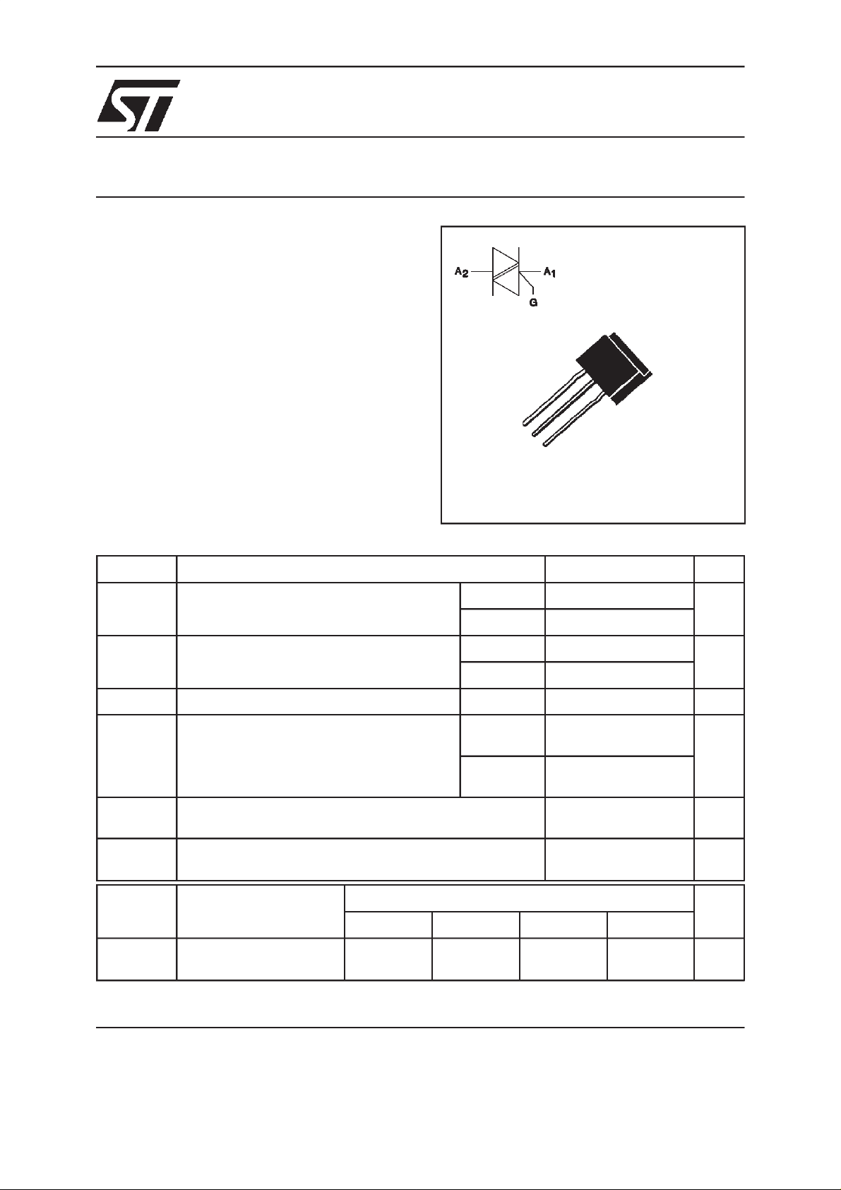
DESCRIPTION
The TLC116 ---> TLC386 T/D/S/A triac family
uses a high performance glass passivated PNPN
technology.
These parts are suitable for general purpose applications where gate high sensitivity is required.
Application on 4Q such as phase control and static
T/D/S/A
SENSITIVEGATE TRIACS
A
1
A
2
G
TL
(Plastic)
ABSOLUTERATINGS (limitingvalues)
Symbol Parameter Value Unit
I
T(RMS)
I
TSM
I2tI
dI/dt Critical rate of rise of on-state current
Tstg
Tj
Tl Maximum lead temperature for soldering during 4 s at 4.5 mm
Symbol Parameter TLC Unit
RMS on-state current
(360°conduction angle)
Non repetitive surge peak on-state current
( Tj initial= 25°C)
2
t value tp = 10 ms 4.5 A2s
Gate supply : IG= 50mA diG/dt = 0.1A/µs
Storage and operating junction temperature range - 40 to + 150
from case
116 T/D/S/A 226 T/D/S/A 336 T/D/S/A 386 T/D/S/A
Tl= 40°C3 A
Ta = 25°C 1.3 (1)
tp = 8.3 ms 31.5 A
tp = 10 ms 30
Repetitive
F = 50 Hz
Non
Repetitive
10 A/µs
50
- 40 to + 110
230
°C
°
°
C
C
V
DRM
V
RRM
(1) With Cu surface 1cm2.
Repetitive peak off-state
voltage Tj = 110°C
February 1999 Ed: 1A
200 400 600 700 V
1/5
TLC 116 T/D/S/ A ---> TLC386 T/ D /S / A
THERMAL RESISTANCES
Symbol Parameter Value Unit
Rth (j-a) Junction to ambient on printed circuit with Cu surface 1cm
Rth (j-l) DC Junction leads for DC 20 °C/W
Rth (j-l) AC Junction leads for 360° conduction angle ( F= 50 Hz) 15 °C/W
2
50 °C/W
GATECHARACTERISTICS (maximumvalues)
P
= 0.1W PGM=2W(tp=20µs) IGM=1A(tp=20µs) VGM= 16V (tp = 20 µs).
G (AV)
ELECTRICAL CHARACTERISTICS
Symbol Test Conditions Quadrant Suffix Unit
TDSA
IGTVD=12V (DC) RL=33Ω Tj=25°C I-II-III MAX 5 5 10 10 mA
IV MAX 5 10 10 25
V
GT
V
GD
tgt VD=V
I
L
VD=12V (DC) RL=33Ω Tj=25°C I-II-III-IV MAX 1.5 V
VD=V
DRMRL
DRMIG
dIG/dt = 0.5A/µs
IG= 1.2 I
=3.3kΩ Tj=110°C I-II-III-IV MIN 0.2 V
= 40mA
GT
Tj=25°C I-II-III-IV TYP 2 µs
Tj=25°C I-III-IV MAX 15 15 25 25 mA
II 15 15 25 25
IH*I
VTM*ITM= 4A tp= 380µs Tj=25°C MAX 1.85 V
I
DRM
I
RRM
dV/dt * Linear slope up to
(dV/dt)c * (dI/dt)c = 1.3A/ms Tj=110°C TYP1155V/µs
* For either polarity of electrodeA2voltage with reference to electrode A1.
2/5
= 100mA gate open Tj=25°C MAX 15 15 25 25 mA
T
V
V
VD=67%V
gate open
DRM
RRM
Rated
Rated
DRM
Tj=25°C MAX 0.01 mA
Tj=110°C MAX 0.75
Tj=110°C TYP 10 10 20 20 V/µs
 Loading...