

SGS Thomson Microelectronics TL431IN, TL431ID, TL431CZ, TL431IZ, TL431AIZ Datasheet
...
PROGRAMMABLE VOLTAGE REFERENCE
.
ADJUSTABLE OUTPUTVOLTAGE :
2.5 to 36V
.
SINK CURRENTCAPABILITY :1 to 100mA
.
TYPICALOUTPUT IMPEDANCE: 0.22Ω
.
1%AND 2% VOLTAGEPRECISION
TL431
Z
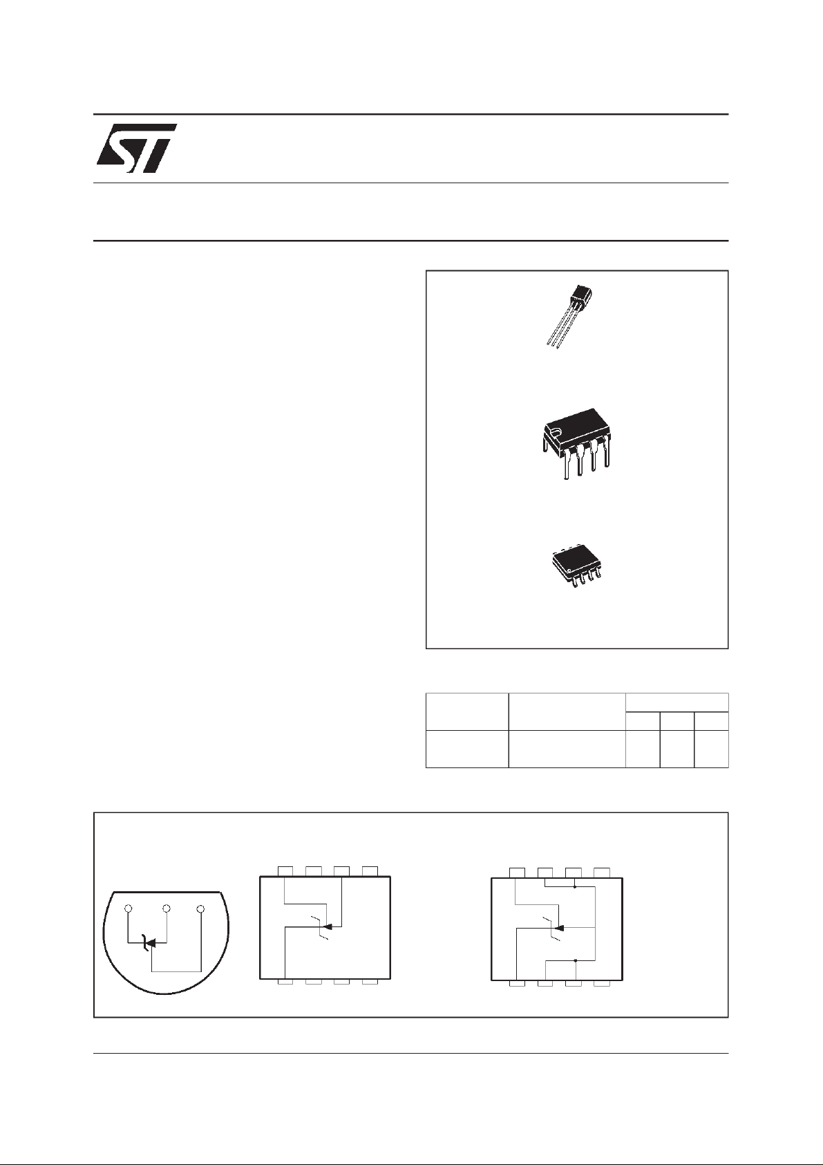
TO92
(Plastic Package)
N
DIP8
(Plastic Package)
DESCRIPTION
The TL431is a programmableshuntvoltagereference with guaranteed temperature stability over
the entire temperature range of operation.
The output voltage may be set to any value between V
externalresistors.
The TL431operateswithawide currentrangefrom
1 to 100mA with a typical dynamic impedance of
0.22Ω.
PIN CONNECTIONS
Cathode Anode Reference
(approximately2.5V) and 36Vwith two
ref
TO92
(Topview)
123
DIP8
(Top view)
8765
1234
(Batwing Plastic Micropackage)
ORDER CODES
Part number Temperature Range
o
TL431C/AC 0
TL431I/AI -40
1 - Cathode
2 - N.C.
3 - N.C.
4 - N.C.
5 - N.C.
6 -Anode
7 - N.C.
8 - Reference
C, +70oC •••
o
C, +105oC •••
SO8
(Top view)
8765
1234
D
SO8
Package
ZND
1 - Cathode
2 -Anode
3 -Anode
4 - N.C.
5 - N.C.
6 -Anode
7 -Anode
8 - Reference
November 1998
1/9
TL431
ABSOLUTE MAXIMUM RATINGS
Symbol Parameter Value Unit
V
KA
I
K
I
ref
T
oper
T
stg
OPERATING CONDITIONS
Symbol Parameter Value Unit
V
KA
I
K
ELECTRICALCHARACTERISTICS
=25oC (unless otherwisespecified)
T
amb
Symbol Parameter
V
ref
∆V
ref
∆V
ref
∆V
KA
Iref Reference InputCurrent - (figure 2)
∆I
ref
I
min
I
off
| Dynamic Impedance - (figure 1, note 2)
|Z
KA
Cathode to Anode Voltage 37 V
Continuous Cathode Current Range -100 to +150 mA
Reference Input Current Range -0.05 to +10 mA
Operating Free-air Temperature Range TL431C/AC
TL431I/AI
0 to +70
-40 to +105
Storage Temperature Range -65 to +150
Cathode to Anode Voltage V
to 36 V
ref
Cathode Current 1 to 100 mA
TL431C TL431AC
Min. Typ. Max. Min. Typ. Max.
Reference InputVoltage - (figure1)
V
KA=Vref,IK
= 10mA T
≤ T
T
min.
amb
≤ T
max.
amb
=25oC
2.44
2.423
2.495 2.55
2.567
2.47
2.453
2.495 2.52
2.537
Reference InputVoltage Deviation Over
Temperature Range - (figure 1, note1)
V
KA=Vref,IK=
10mA,T
min.
≤ T
amb
≤ T
max.
317 315
Ratio of Change in Reference Input Voltage to
Change in Cathode to Anode Voltage - (figure 2)
=10mA ∆VKA= 10V to V
I
K
= 10mA, R1=10kΩ,R2=∞
I
K
∆VKA= 36V to 10V
=25oC
T
amb
≤ T
T
min.
amb
≤ T
ref
max.
-1.4-1-2.7
-2
1.8 4
5.2
-1.4-1-2.7
-2
1.8 4
5.2
Reference InputCurrent Deviation Over
Temperature Range - (figure 2)
= 10mA, R1=10kΩ,R2=∞
I
K
T
min.
≤ T
amb
≤ T
max.
0.4 1.2 0.4 1.2
Minimum Cathode Current for Regulation - (figure 1)
V
KA=Vref
0.5 1 0.5 0.6
Off-State CathodeCurrent - (figure 3) 2.6 1000 2.6 1000 nA
V
KA=Vref
, ∆IK= 1 to 100mA, f ≤ 1kHz 0.22 0.5 0.22 0.5
o
C
o
C
mV/V
Unit
V
mV
µA
µA
mA
Ω
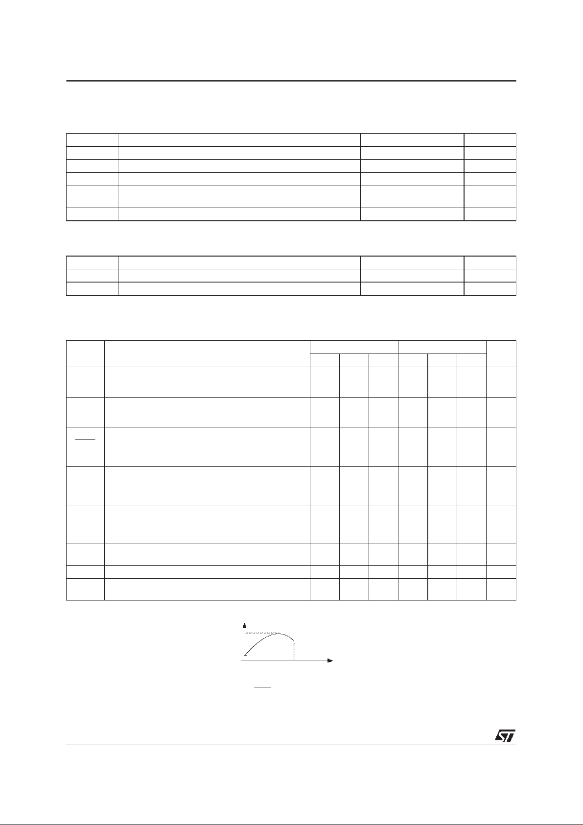
Notes : 1. ∆V
2. The dynamic Impedance is defined as |ZKA| =
isdefined as the difference between the maximum and minimum values obtained over the full temperature
ref
range.
∆V
ref=Vrefmax.-Vrefmin
2/9
V
V
ref ma x.
re fmin.
T1
∆V
∆I
T2
KA
K
Temp era ture
ELECTRICALCHARACTERISTICS
=25oC (unless otherwisespecified)
T
amb
Symbol Parameter
V
∆V
∆V
∆V
Iref Reference InputCurrent - (figure 2)
∆I
I
|Z
Reference InputVoltage - (figure1)
ref
ref
ref
KA
ref
min
I
off
| Dynamic Impedance - (figure 1, note 2)
KA
V
KA=Vref,IK
Reference InputVoltage Deviation Over
Temperature Range - (figure 1, note1)
V
KA=Vref,IK=
Ratio of Change in Reference Input Voltage to
Change in Cathode to Anode Voltage - (figure 2)
=10mA ∆VKA= 10V to V
I
K
= 10mA, R1=10kΩ,R2=∞
I
K
Reference InputCurrent Deviation Over
Temperature Range - (figure 2)
= 10mA, R1=10kΩ,R2=∞
I
K
Minimum Cathode Current for Regulation - (figure 1)
V
KA=Vref
Off-State CathodeCurrent - (figure 3) 2.6 1000 2.6 1000 nA
V
KA=Vref
= 10mA T
≤ T
T
min.
10mA,T
min.
∆VKA= 36V to 10V
=25oC
T
amb
≤ T
T
min.
≤ T
T
min.
, ∆IK= 1 to 100mA, f ≤ 1kHz 0.22 0.5 0.22 0.5
amb
≤ T
amb
amb
≤ T
amb
≤ T
≤ T
max.
≤ T
max.
max.
TL431
TL431I TL431AI
Min. Typ. Max. Min. Typ. Max.
=25oC
amb
max.
ref
2.44
2.41
2.495 2.55
2.58
2.47
2.44
2.495 2.52
730 730
-1.4-1-2.7
-1.4-1-2.7
-2
1.8 4
1.8 4
6.5
0.8 2.5 0.8 1.2
0.5 1 0.5 0.7
Unit
V
2.55
mV
mV/V
-2
µA
6.5
µA
mA
Ω
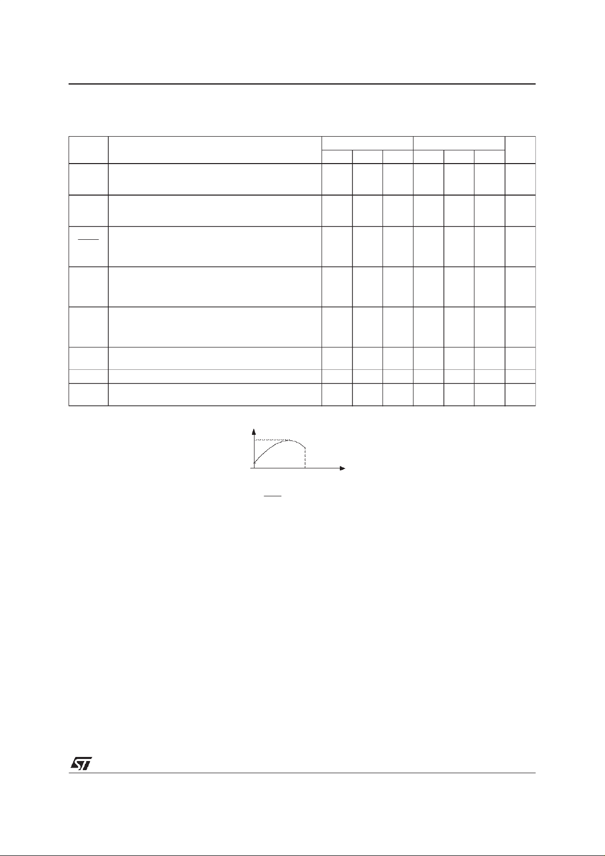
Notes : 1. ∆V
2. The dynamic Impedance is defined as |ZKA| =
isdefined as the difference between the maximum and minimum values obtained over the full temperature
ref
range.
∆V
=V
refmax.-Vrefmin
ref
V
ref ma x.
V
re fmin.
T1 T2
∆V
Temp era ture
KA
∆I
K
3/9
 Loading...