

SGS Thomson Microelectronics TL1431C, TL1431ACZ, TL1431ACD, TL1431IZ, TL1431IN Datasheet
...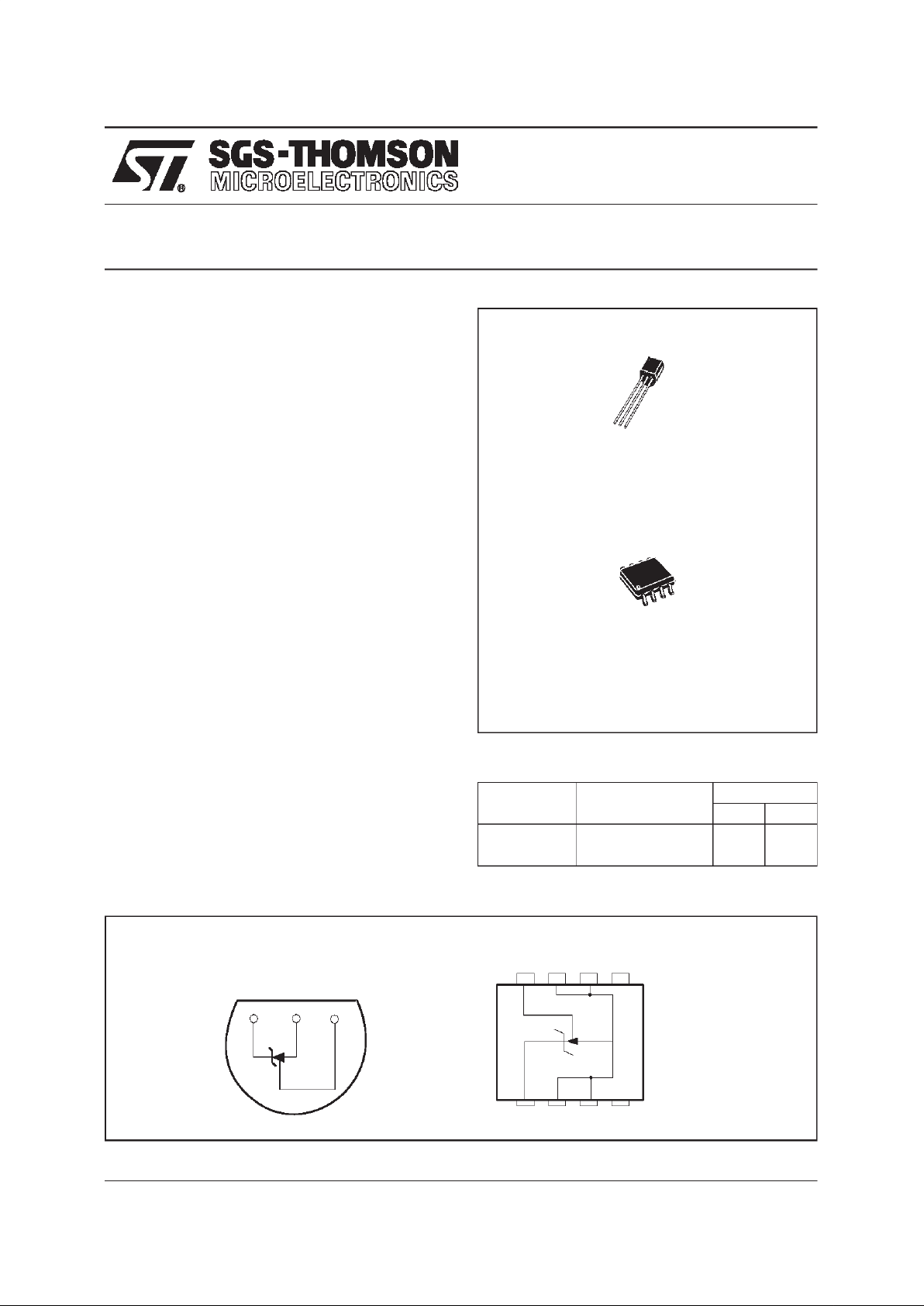
1 - Cathode
2 - Anode
3 - Anode
4 - N.C.
5 - N.C.
6 - Anode
7 - Anode
8 - Reference
Z
TO92
(Plastic Package)
.
ADJUSTABLE OUTPUT VOLTAGE:
V
ref
to 36V
.
SINK CURRENTCAPABILITY : 1 to 100mA
.
TYPICALOUTPUT IMPEDANCE: 0.2Ω
.
0.4% AND 0.25%VOLTAGEPRECISION
DESCRIPTION
The TL1431is a programmableshunt voltagereference with guaranteed temperaturestability over
the entire temperature range of operation.
The output voltage may be set to any value between V
ref
(approximately2.5V)and 36V with two
external resistors.
The TL1431 operates with a wide current range
from1 to100mAwith a typicaldynamicimpedance
of 0.2Ω.
PIN CONNECTIONS
8765
1234
SO8
(Top view)
Cathode Ano d e Reference
123
TO92
(Top view)
D
SO8
(Batwing Plastic Micropackage)
PROGRAMMABLE VOLTAGE REFERENCE
TL1431
ORDER CODES
Part number Temperature Range
Package
ZD
TL1431C/AC -20
o
C, +70oC ••
TL1431I/AI -40
o
C, +105oC ••
March 1998 1/8
ABSOLUTE MAXIMUM RATINGS
Symbol Parameter Value Unit
V
KA
Cathode to Anode Voltage 37 V
I
K
Continuous Cathode CurrentRange -100 to +150 mA
I
ref
Reference Input Current Range -0.05 to +10 mA
T
oper
Operating Free-air Temperature Range TL1431C/AC
TL1431I/AI
-20 to +70
-40 to +105
o
C
T
stg
Storage Temperature Range -65 to +150
o
C
OPERATING CONDITIONS
Symbol Parameter Value Unit
V
KA
Cathode to Anode Voltage V
ref
to 36 V
I
K
Cathode Current 1 to 100 mA
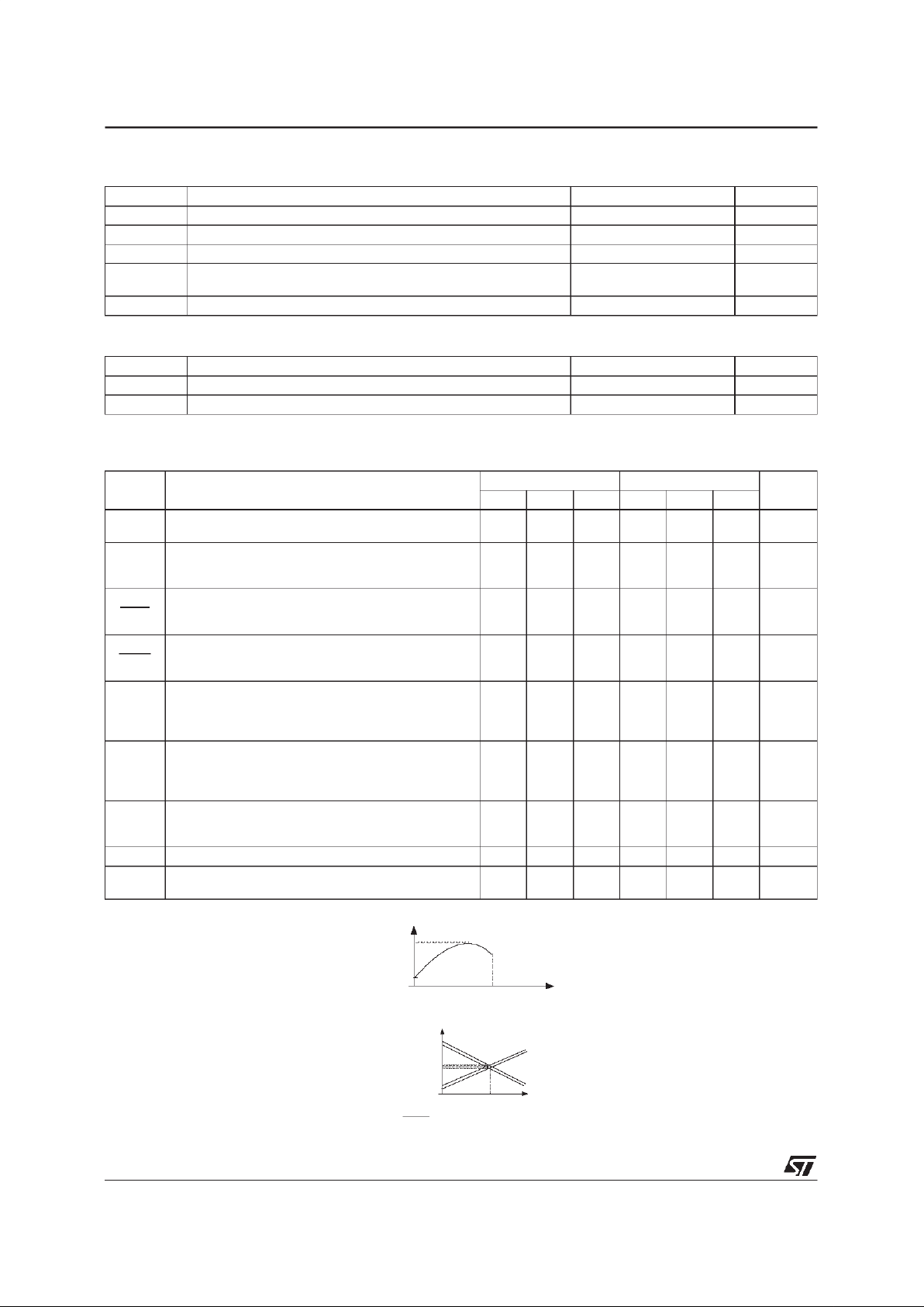
ELECTRICALCHARACTERISTICS
T
amb
=25oC (unless otherwise specified)
Symbol Parameter
TL1431C TL1431AC
Unit
Min. Typ. Max. Min. Typ. Max.
V
ref
Reference InputVoltage - (figure1)
V
KA=Vref,IK
= 10mA T
amb
=25oC 2.490 2.500 2.510 2.493 2.500 2.507
V
∆V
ref
Reference InputVoltage Deviation Over
Temperature Range - (figure 1, note1)
V
KA=Vref,IK=
10mA, T
min.
≤ T
amb
≤ T
max.
320 320
mV
∆V
ref
∆T
Temperature Coefficient of Reference Input
Voltage - (note 2)
V
KA=Vref,IK
= 10mA, T
min.
≤ T
amb
≤ T
max.
±13 ±90 ±13 ±90
ppm/
o
C
∆V
ref
∆V
KA
Ratio of Change in Reference Input Voltage to
Change in Cathode to Anode Voltage - (figure 2)
I
K
= 10mA, ∆VKA= 36V to 3V -2 -1.1 -2 -1.1
mV/V
Iref Reference InputCurrent - (figure 2)
I
K
= 10mA, R1= 10kΩ,R2=∞
T
amb
=25oC
T
min.
≤ T
amb
≤ T
max.
1.5 2.5
3
1.5 2.5
3
µA
∆I
ref
Reference InputCurrent Deviation Over
Temperature Range - (figure 2)
I
K
= 10mA, R1= 10kΩ,R2=∞
T
min.
≤ T
amb
≤ T
max.
0.2 1.2 0.2 1.2
µA
I
min
Minimum Cathode Currentfor Regulation - (figure
1)
V
KA=Vref
0.5 1 0.5 0.6
mA
I
off
Off-State Cathode Current - (figure 3) 180 500 180 500 nA
|Z
KA
| Dynamic Impedance - (figure 1, note 3)
V
KA=Vref
, ∆IK= 1 to 100mA, f ≤ 1kHz 0.2 0.5 0.2 0.5
Ω
T1
T2
Temp era ture
V
ref ma x.
V
re fm in.
Notes : 1. ∆V
ref
is defined as thedifference between the maximum and minimum values obtained over the full temperature
range.
∆V
ref=Vref max.-Vref min
2. The temperature coefficientis defined as the slopes (positiveand negative) of the voltage vs temperature limits whithin
which the reference voltage isguaranteed.
3. The dynamic Impedance is defined as |Z
KA
| =
∆V
KA
∆I
K
25 C
Te mpe rature
max
2.5V
min
-
n
p
p
m
/
C
+
n
p
p
m
/
C
TL1431
2/8
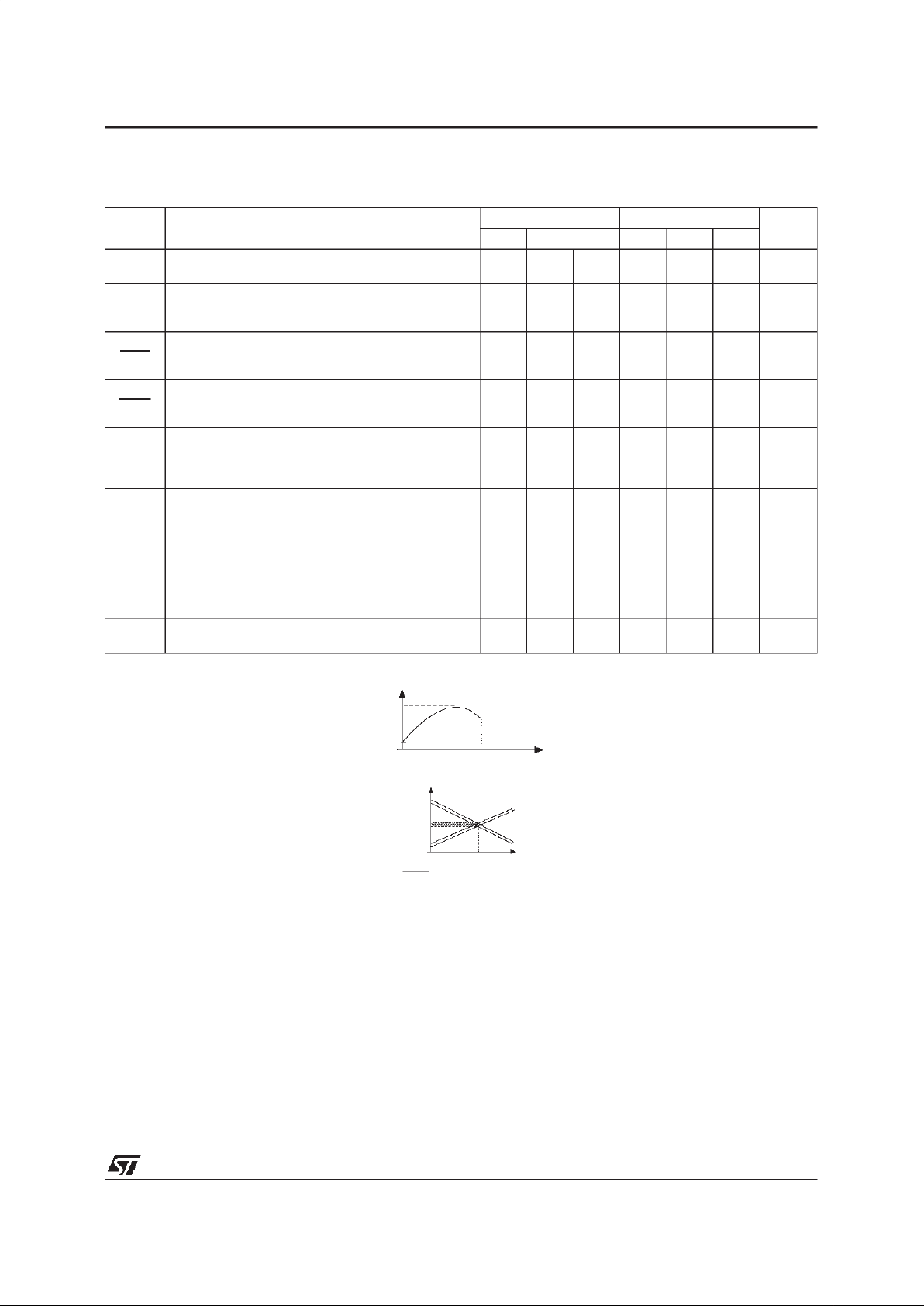
ELECTRICALCHARACTERISTICS
T
amb
=25oC (unless otherwise specified)
Symbol Parameter
TL1431I TL1431AI
Unit
Min. Typ. Max. Min. Typ. Max.
V
ref
Reference InputVoltage - (figure1)
V
KA=Vref,IK
= 10mA T
amb
=25oC 2.490 2.500 2.510 2.493 2.500 2.507
V
∆V
ref
Reference InputVoltage Deviation Over
Temperature Range - (figure 1, note1)
V
KA=Vref,IK=
10mA, T
min.
≤ T
amb
≤ T
max.
730 730
mV
∆V
ref
∆T
Temperature Coefficient of Reference Input
Voltage - (note 2)
V
KA=Vref,IK
= 10mA, T
min.
≤ T
amb
≤ T
max.
±22 ±100 ±22 ±100
ppm/
o
C
∆V
ref
∆V
KA
Ratio of Change in Reference Input Voltage to
Change in Cathode to Anode Voltage - (figure 2)
I
K
= 10mA, ∆VKA= 36 to 3V -1.1 -2 -1.1 -2
mV/V
Iref Reference InputCurrent - (figure 2)
I
K
= 10mA, R1= 10kΩ,R2=∞
T
amb
=25oC
T
min.
≤ T
amb
≤ T
max.
1.5 2.5
3
1.5 2.5
3
µA
∆I
ref
Reference InputCurrent Deviation Over
Temperature Range - (figure 2)
I
K
= 10mA, R1= 10kΩ,R2=∞
T
min.
≤ T
amb
≤ T
max.
0.5 1 0.8 1.2
µA
I
min
Minimum Cathode Currentfor Regulation
(figure 1)
V
KA=Vref
0.5 1 0.5 0.7
mA
I
off
Off-State Cathode Current - (figure 3) 180 500 180 500 nA
|Z
KA
| Dynamic Impedance - (figure 1, note 3)
V
KA=Vref
, ∆IK= 1 to 100mA, f ≤ 1kHz 0.2 0.5 0.2 0.5
Ω
T1 T2
Tempera ture
V
re fm ax.
V
ref min.
Notes : 1. ∆V
ref
is defined as thedifference between the maximum and minimum values obtained over the full temperature
range.
∆V
ref
=V
ref max.-Vref min
2. The temperature coefficientis defined as the slopes (positiveand negative) of the voltage vs temperature limits whithin
which the reference voltage isguaranteed.
3. The dynamic Impedance is defined as |Z
KA
| =
∆V
KA
∆I
K
25
C
Te mpe rature
max
2.5V
min
-
n
p
p
m
/
C
+
n
p
p
m
/
C
TL1431
3/8
 Loading...