


1/21July 2003
■ 4-CHANNEL S ERIAL-IN PARALLEL-IN LOW
SIDE PRE-FET DRIVER
■ DEVICES ARE CASCADABLE
■ INTERNAL 55V INDUCTIVE LOAD CLAMP
AND VGS PROTECTION CLAMP FOR
EXTERNAL POWER FETS
■ INDEPENDENT SHORTED-LOAD AND
SHORT-TO-BATTERY FAULT DETECTION
ON ALL GATE TERMINALS
■ INDEPENDENT OFF-STATE OPEN-LOAD
FAULT SENSE
■ OVER-BATTERY-VOLTAGE LOCKOUT
PROTECTION AND FAULT REPORTING
■ UNDER-BATTERY VOLTAGE LOCKOUT
PROTECTION
■ ASYNCRONOUS OPEN-GATE FAULT FLAG
■ DEVICE OUTPUT CANBE WIREDOR WITH
MULTIPLE DEVICES
■ FAULT STATUS RETURNED THROUGH
SERIAL O UTPUT TERMINAL
■ INTERNAL GL OBA L POWER-ON RESET OF
DEVICE AND EXTERNAL RESET TERMINAL
■ HIGH IMPEDANCE CMOS COMPATIBLE
INPUTS WITH HYSTERESIS
■ TRANSITION FROM THE GATEOUTPUT TO
A LOW DUTY CY CLE PWM MODE WHEN A
SHORTEDLOADFAULTOCCURS
DESCRIPTION
The STPIC44L02 is a low-side predriver that
provides serial and parallel input interfaces to
control four external FET power s w itches.
It is mainly desi gned to provide low-frequency
switching, inductive load applicati ons such as
solenoids and relays. Fault status is available in a
serial-data format. Each driver channel has
independent off-state open-load detection and
on-state shorted load short to battery detection.
The STPIC44L02 offers a batteryover voltage and
undervoltage detection and shutdown. If a fault
occurs while using the STPIC44L02, the channel
transitates into a low duty cycle , pulse width
modulated (PWM) signal as long as the fault is
present.
These devices provide control of output channels
through a serial input interface or a parallel input
interface. A command to enable the output from
either interface enables the respective channels
gate output to the external FET. The serial
interface is recom mended when the number of
signals between t he control device and the
predriver are minimized and the speed of
operation is not critical. In applications where the
predriver must respond very quickly or
asynchronously, the parallel input interface is
recommended.
For serial operation, the control device must
transitate C S
from hi gh to low to activate the serial
input interface. When this occurs, SDO, is
enabled, fault data is latched into the serial
interface, and the fault flag is refreshed. Data is
clocked into the serial registers on low to high
transitions of SCLK through SDI. Each string of
data must con sist of at least four bits of data. In
applications where multiple devices are cascaded
together, t he string of data must c onsist of four bits
for each device. A high data bit turns the
respective output c hannel on and a low data bit
turns it off. Fault data for the device is clocked out
of SDO as serial input data is clocked into the
device. Fault data consists of fault flags for
shorted load and open load flags (bits 0-3) for
each of the four output channels. Fault regist er
bits are set or cleared asynchronously to ref lect
the current state of the hardware. A fault must be
present w hen CS
is transitated from high to low to
be captured and reported in the serial fault data.
New faults cannot be captured in the serial
register when CS
is low. CS must be transitated
high after all of the serial dat a has been clocked
into the device. A low to high transition of CS
transfers t he last four bits of serial data to t he
STPIC44L02
4 CHANNEL SERIAL AND PARALLEL
LOW SIDE PRE-FET DRIVER
SOP
STPIC44L02
2/21
output buffer that puts SDO in a high im pedance
state and clears and reenables the fault register.
The STPIC44L02 was designed to allow the serial
input interfaces of multiple devices to be cascated
together to simplify the serial in terfac e of the
controller. Serial input data flows through the
device and is transferred out SDO following t he
fault data in c as caded configurations.
For parallel operation, data is transferred directly
from the parallel input interface IN0-IN3 to the
respective GATE(0-3) output asy nc hronous ly.
SCLK or CS
is not required for parallel control. A 1
on the parallel input turns the respective channel
on, where as a 0 turns it off. Note that either the
serial input interface or the parallel input in terface
can enable a channel. Under parallel operation,
fault data must still be collected t hrough the serial
data interface.
The predriver monitors the drain voltage for each
channel to detect shorted load or open load fault
conditions, in t he on and off st ate respectively.
These devices offer the option of using an
internally genera ted fault reference voltage or an
externally supplied fault reference voltage through
V
COMP
for fault detection. The internal fault
reference is selected by c onnecting V
COMPEN
to
GND and the external reference is selected by
connecting V
COMPEN
to VCC. The drain voltage is
compared to the fault reference when the channel
is turned on to detect shorted load conditions and
when t he channel is off to detect open lo ad
conditions. If a fault occurs, the channel
transitates into a low duty cycle , pulse width
modulated (PWM) signal as long as the fault is
present. Shorted load fault c onditions must be
present for at least the shorted l oad deglicth time,
t
(STBDG)
, to be flagged as a fault. A fault flag is
sent to the control device as well as the serial fault
register bits. More detail on fault detection
operation is presented in the device operation
section of this datasheet.
The device provides prote ction from over battery
voltage and under ba ttery voltage conditions
irrespective of the state of the output channels.
When the battery voltage is greater than the
overvoltage threshold or les s than the
undervotlage threshold, all channels are disabled
and a fault flag is generated. Battery voltage f aults
are not reported in the serial fault data. The
outputs return to normal operation onc e the
battery voltage fault has been corrected. When an
over battery/under battery voltage condition
occurs, the device reports the battery fault, but
disables fault reporting for open and shorted load
conditions. Fault reporting for open and shorted
load conditions are reenabled after the battery
fault condition has been corrected.
This device provides inductive transient protection
on all channels. The drain voltage is clamped to
protect the FET. The c lamp voltage is defined by
the sum of V
CC
and turn on voltage of the external
FET. The predriver also provides a gate to source
voltage (V
GS
) clamp to protect the gate source
terminals of the power FET from exceeding their
rated voltages. An external active low RESET
is
provided to clear all register and flags in the
device. GATE(0-3) outputs are disabled after
RESET has been pulled low.
The d ev ice provide pull-down resistors on all
inputs except CS
and RESET. A pull-up resistor is
usedon CS
and RESET.
ORDERING CODES
Type Package Comments
STPIC44L02PTR SSOP24 (Tape & Reel) 1350 parts per reel

STPIC44L02
3/21
Figure1 : Schematic Diagram
STPIC44L02
4/21
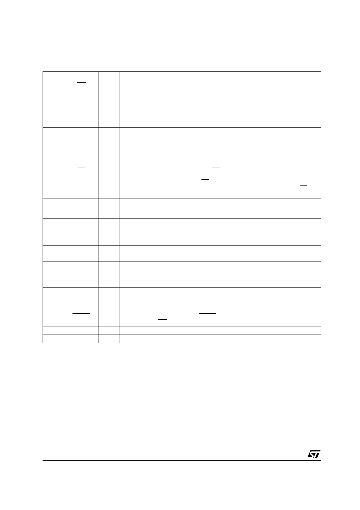
PIN DESCRIPTION
PIN No SYMBOL I/O NAME AND FUNCTION
1FLT
I Fault Flag. FLT is a logic level open-drain output that provides a real time fault flag for
shorted-load, open-load, over-battery voltage, under-battery voltage faults. The
device can be ORed with FLT terminals on other devices for interrupt handling. FLT
requires an external pull-up resistor.
2 VCOMPEN I Fault reference voltage select. VCOMPEN selects the internally generated fault
reference voltage (0) or an external fault reference (1) to be used in the shorted and
open load fault detection circuitry.
3 VCOMP I Fault reference voltage. VCOMP provides an external fault reference voltage for the
shorted-load and open load fault detection circuitry.
4
5
6
7
IN0
IN1
IN2
IN3
I Parallel gate driver. IN0 trough In3 are real-time controls for the gate pre drive
circuitry. They are CMOS compatible with hysteresis.
8CS
I Chip select. A high to low transition on CS enables SDO, latches fault data into the
serial interface, and refreshes FLT. When CS is high, the fault register can change
fault status. On the falling edge of CS
, fault data is latched into the serial output
register and transferred using SDO and SCLK. On a low to high transition of CS
,
serial data is latched in to the output control register.
9 SDO O Serial data output. SDO is a 3-state output that transfers fault data to the controlling
device. It also passes serial input data to the next stage for cascaded operation. SDO
is taken to a high-impedance state when CS
is in a high state.
10 SDI I Serial data input. Output control data is clocked into the serial register through SDI. A
1 on SDI commands a particular gate output on and a 0 turns it off.
11 SCLK I Serial clock. SCLK clocks the shift register. Serial data is clocked into SDI and serial
fault data is clocked out of SDO on the falling edge of the serial clock.
12 V
CC
I Logic Supply Voltage
13 GND I Ground
14
16
19
21
DRAIN0
DRAIN1
DRAIN2
DRAIN3
I FET drain inputs. DRAIN0 through DRAIN3 are used for both open load and short
circuit fault detection at the drain of the external FETs. They are also used for
inductive transient protection.
15
17
18
20
GATE0
GATE1
GATE2
GATE3
O Gate drive output. GATE0 through GATE3 outputs are derived from the V
BAT
supply
voltage. Internal clamps prevent voltages on these nodes from exceeding the VGS
rating of most FETs.
22 RESET
I Reset. A high-to low transition of RESET clears all registers and flags. Gate outputs
turn off and the FLT
flag is cleared.
23 NC Not Connected
24 V
BAT
I Battery Supply Voltage
STPIC44L02
5/21
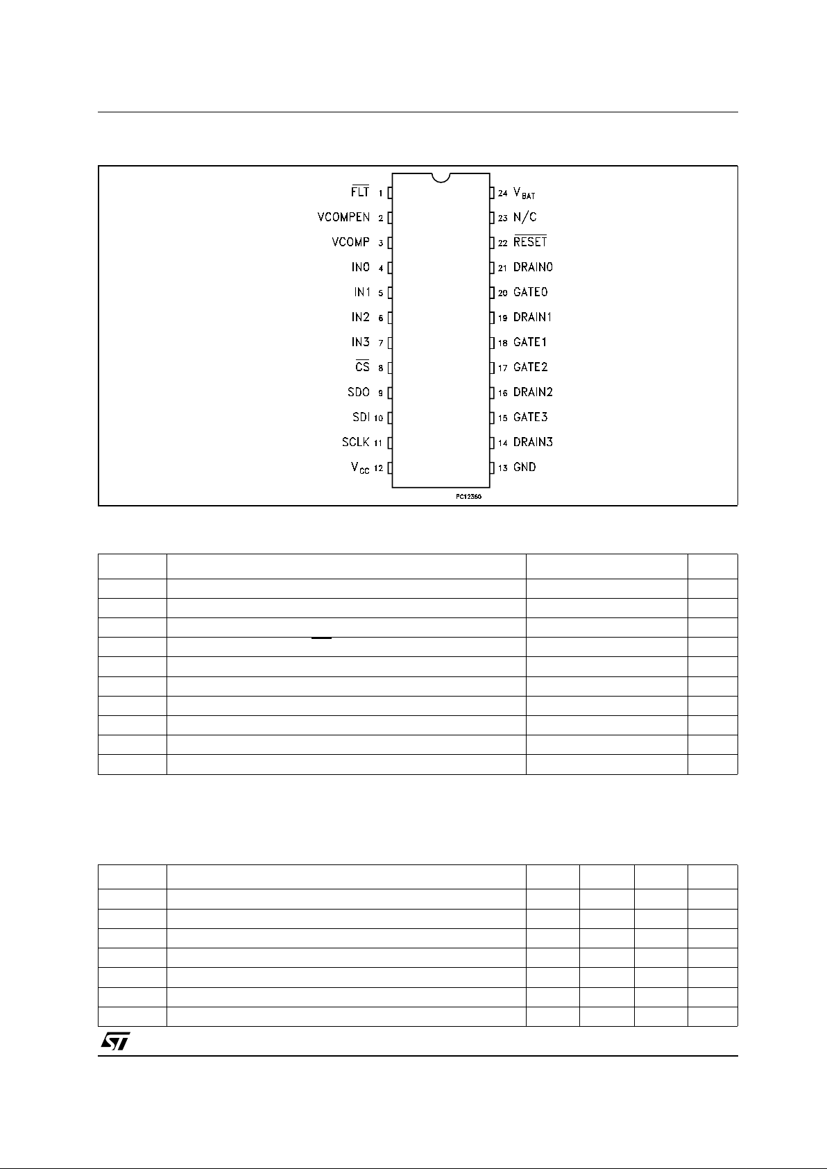
Figure2 : Pin Configuration
ABSOLUTE MAXIMUM RATING S
Absolute Maximum Ratings are those values beyond which damage to the device may occur. Functional operation under these condition is
not implied.
Note 1: All voltage value are with respect to GND
RECOMMENDED OPERATING CONDITIONS
Symbol Parameter Value Unit
V
CC
Logic Supply Voltage (See Note 1)
-0.3 to 7 V
V
BAT
Battery Supply Voltage
-0.3 to 60 V
V
I
Logic Input Voltage Range
-0.3 to 7 V
V
O
Output Voltage (SDO and FLT)
-0.3 to 7 V
V
O
Output Voltage
-0.3 to 15 V
V
I
Logic Input Voltage Range
-0.3 to 7 V
V
DS
Drain to Source Voltage
-0.3 to 60 V
T
C
Operating Case Temperature Range
-40 to +125 °C
T
J
Maximum Junction Temperature
150 °C
T
stg
Storage Temperature Range
-40 to +150 °C
Symbol Parameter Min. Min. Max. Unit
V
CC
Logic Supply Voltage 4.5 5 5.5 V
V
BAT
Battery Supply Voltage 8 24 V
V
IH
High Level Input Voltage 0.85V
CC
V
CC
V
V
IL
Low Level Input Voltage 0 0.15V
CC
V
t
s
Set-up Time, SDI High Before SCLK ↑ 10 ns
t
h
Hold Time, SDI High After SCLK ↑ 10 ns
T
C
Operating Case Temperature -40 125 °C

STPIC44L02
6/21
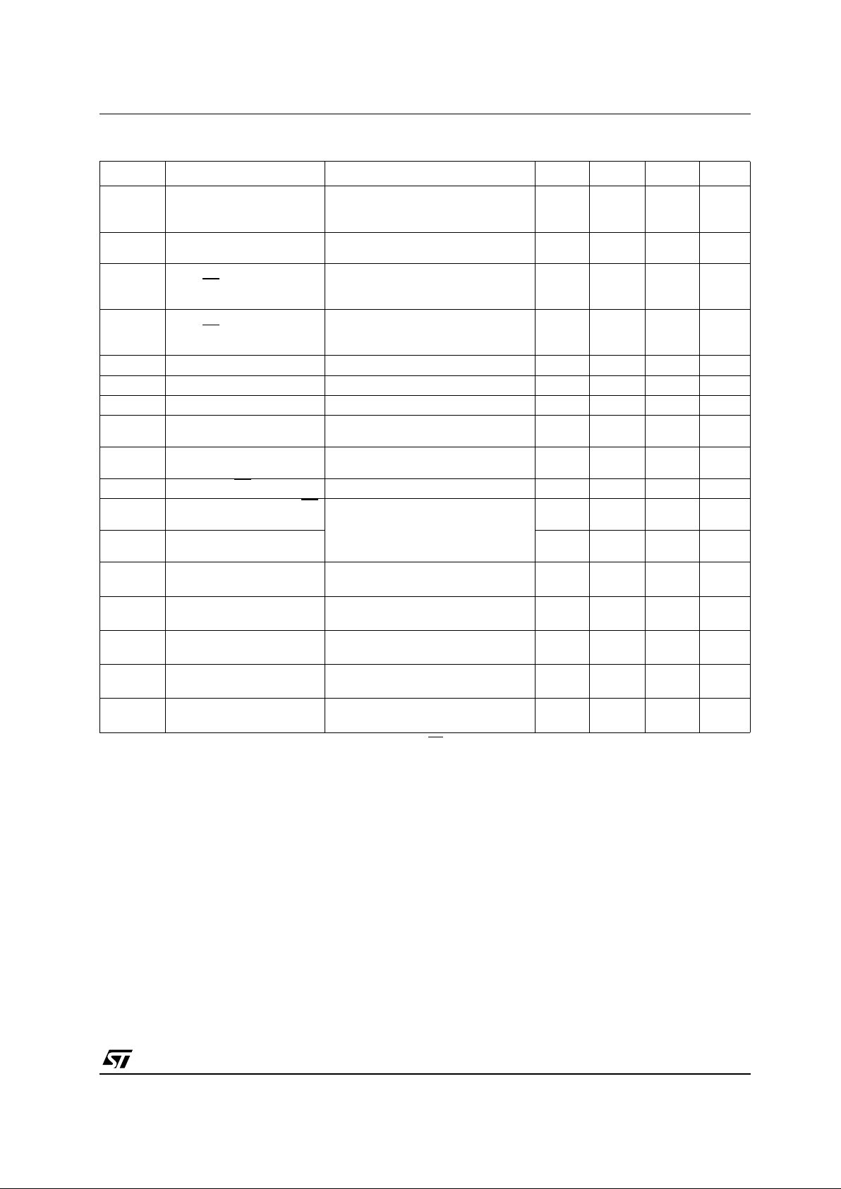
ELECTRICAL CHARACTERISTICS OVER RECOMMENDED OPERATING F REE-AIR
TEMPERATURE RANGE (unless otherwise specified.)
Symbol Parameter Test Conditions Min. Typ. Max. Unit
I
BAT
Supply Current All Outputs OFF, V
BAT
= 12V 50 150 250 µA
I
CC
Supply Current All Outputs OFF, V
BAT
= 5.5V 0.5 1.5 3 mA
V
(ovsd)
Over Battery Voltage
Shutdown
Gate Disabled (see figure 21) 32 34 36 V
V
hys(ov)
Over Battery Voltage Reset
Hysteresys
0.1 0.3 0.5 V
V
(uvsd)
Under Battery Voltage
Shutdown
Gate Disabled (see figure 20) 4.1 4.8 5.4 V
V
hys(uv)
Under Battery Voltage
Reset Hysteresys
50 150 300 mV
V
G
Gate Drive Voltage V
BAT
=8to24V IO=100µA 7 13.5 V
V
BAT
= 5.5 to 8V IO=100µA5 8V
I
O(H)
Maximum Current Output
For Drive Terminal Pull-Up
VO= GND 0.5 1.8 2.5 mA
I
O(L)
Maximum Current Output
For Drive Terminal
Pull-Down
V
O
= 7V 0.5 1.2 2.5 mA
V
(stb)
Short to Battery, Shorted
Load, Open Load Detection
Voltage
V
COMPEN
= L 1.1 1.25 1.4 V
V
hys(stb)
Short to Battery Hysteresys 30 mV
V
D(open)
Open Load OFF State
Detection Voltage
Threshold
V
COMPEN
= L 1.1 1.25 1.4 V
V
hys(open)
Open Load Hysteresys 60 mV
I
I(open)
Open Load Off State
Detection Current
V
DRAIN=VREF
= 1.25V 30 60 80 µA
V
DRAIN
= 24V (see figure 24) 250 µA
I
I(PU)
Input Pull-up Current VCC=5V VI=0 10 µA
I
I(PD)
Input Pull-down Current VCC=5V VI=5V 10 µA
V
hys
Input Voltage Hysteresys VCC= 5V 0.6 0.85 1.1 V
V
O(SH)
High Level Serial Output
Voltage
IO= 1mA 0.8V
CC
V
V
O(SL)
Low Level Serial Output
Voltage
IO= 1mA 0.1 0.4 V
I
OZ(SD)
3-State Current Serial Data
Output
VCC= 0 to 5.5V -10 1 10 µA
V
O(CFLT)
Fault Interrupt Output
Voltage
IO= 1mA 0.1 0.5 V
V
I(COMP)
Fault External Reference
Voltage
V
COMPEN
=H 1 3 V
V
C
Output Clamp Voltage dc < 1% tW=100µs 475563V
STPIC44L02
7/21
SWITCHING CHARACTERISTICS (VCC=5V, V
BAT
=5V, TC= 25°C, unlessotherwise specified.)
Note 1: Thetd1is referred to the falling edge of the first clock after theCSfallsdown
Symbol Parameter Test Conditions Min. Typ. Max. Unit
t
(STBFM)
Short to Battery, Shorted
Load, Open Load Fault
Mask Time
(see figures 16, 17) 60 µs
t
(STBDG)
Short to Battery, Shorted
Load, Deglitch Time
(see figures 16, 17) 12 µs
t
PLH
Propagation Turn-On Delay
Time, CS
or IN0-IN3 to
Gate0-Gate3
C
(gate)
= 400pF 3.5 µs
t
PHL
Propagation Turn-Off Delay
Time, CS
or IN0-IN3 to
Gate0-Gate3
C
(gate)
= 400pF 4 µs
t
r1
Rise Time, Gate0-Gate3 C
(gate)
= 400pF 1.5 µs
t
f1
Fall Time, Gate0-Gate3 C
(gate)
= 400pF 2 µs
f
(SCLK)
Serial Clock Frequency 10 MHz
t
rf(SB)
Refresh Time Short to
Battery
(see figure 16) 10 ms
t
W)
Refresh pulse width Short
to Battery
(see figure 16) 68 µs
t
su1
Setup Time CS ↓ to SCLK ↓ (see note 1) (see figure 4) 10 ns
t
pd1
Propagation Delay Time CS
to SDO Valid
R
L
=10KΩ CL= 200pF
(see figure 6)
40 ns
t
pd2
Propagation Delay Time
SCLK to SDO Valid
20 ns
t
pd3
Propagation Delay Time CS
to SDO 3-State
RL=10KΩ CL= 50pF
(see figure 6)
2 µs
t
r2
Rise Time, SDO 3-State to
SDO Valid
RL=10KΩto GND CL= 200pF
Over Battery Fault (see figure 7)
30 ns
t
f2
Fall Time, SDO 3-State to
SDO Valid
RL=10KΩto GND CL= 200pF
No Fault (see figure 8)
20 ns
t
r3
Rise Time, FLT RL=10KΩ CL= 50pF
(see figure 9)
1.2 µs
t
f3
Rise Time, FLT RL=10KΩ CL= 50pF
(see figure 9)
15 ns

STPIC44L02
8/21
Figure3 : Switching Time
Figure4 : Setup Time CS
↓ to SCLK ↓

STPIC44L02
9/21
Figure5 : Propagation Delay Time
Figure6 : Propagation Delay Time
Figure7 : SDO Switching Time

STPIC44L02
10/21
Figure8 : SDO Switching Time
Figure9 : FLT
Switching Time
PRINCIPLES OF OPERATION
SERIAL DATA OPERATION
The STPIC44L02 offers serial input interface to
the m icroc ontro ller to transfer cont rol data to the
predriver and fault data back to the controller. The
serial input interface consists of:
SCLK - Serial C lock
CS
- Chip Select
SDI - Serial Data Input
SDO - SeriaL Data Output
Serial data is shifted into the least significant bit
(LSB) of the SDI shift register on the rising edge of
the first SCLK after CS
has t r ans it ated fro m 1 to 0.
The CS
must be transitated from 1 to 0 before the
falling edge of t he first clock (see n ote 1).
Four clock cycles must occur before CS
transitates high for a proper control of the outputs.
Less than four clock cycles result in fault data
being latched into the output control buffer.
Eight bits data can be shifted into the device, but
the first 4 bits shifted out are always the fault dat a
and the last 4 bits shifted in are always the output
control data. A low-to-high transition on CS
latches the contents of the serial shift register into
the output control register. A logic 0 input to SDI
turns of f the corresponding parallel output and a
logic 1 input t urns the output on (s ee figure 10).
Data is shifted out of SDO on the falling edge of
SCLK. The M SB of fault data is available after CS
is transitated low. The rem aining 3 bits of fault
data are shifted out in the following three clock
cycles. Fault data is latched into the serial register
when CS
is transitated low. A fault must be
present on the high to low transition of CS
to be
captured by the device. The CS
input mus t be
transitated to a high state after t he last bit of serial
data has been cloc k ed into the device. The rising
edge of CS
inhibit SDI puts SDO into a high
impedance s tate, latches the 4 bits of serial data
into the output control register, and clears and
reenables the serial fa ult regist ers (see figure 11).
When a shorted load condit ion occurs, the device
automatically retries the output and the fault clears
after the fault condition has been corrected.

STPIC44L02
11/21
Figure10 : Serial Programming Example
Figure11 : 8-Bit Serial Programming Example (single devi ce)

STPIC44L02
12/21
Figure12 : 8-Bit S erial Programming Example (two predrivers cascated)
Figure13 : Fault Reading Example
PARALLEL INPUT DATA OPERATION
In addition to th e serial interface the STPIC44L02
also provid es a pa rallel interface to the
microcontroller. The output turns on when either
the parallel or the serial interface make it turn on.
The parallel data terminals are real t ime control
inputs for t he outputs drivers. SCLK and CS
are
not required to transfer parallel input data to the
output buffer. Fault data must be read over the
serial data bus as de scribed in the serial data
operation section of this datasheet (see figure 13).
The parallel input must be transitated low and then
high to clear and reenable a gate output after it
has been disabled due to a s horted load fault
condition.
CHIPSET PERFORMANCE UNDER FAULT
CONDITIONS
The STPIC44L02 and power FET arrays are
designed for normal operation over a battery
voltage range of 8V to 24V with load fault
detection from 4.8V to 34V. It offers onboard fault
detection to handle a va riety of faults that may
occur within a system. The circuits primary
function is to prevent damage to the load and the
power FETs in the event that a fault occurs.
Note that unused DRAIN0-DRAIN3 inputs must
be connected to V
BAT
through a pull-up resistor to
prevent false reporting of open load fault
conditions. The circuitry detects the fault, shuts off
the output to the FET and reports t he fault to the
microcontroller. The primary faults under
consideration are:
1) Shorted Load
2) Open Load
3) over battery voltage shutdown
4) Under battery voltage shutdown.
SHORTED LOAD FAULT CONDITION

STPIC44L02
13/21
The STPIC44L02 monitors the drai n voltage of
each channel to detect shorted load conditions.
The onboard deglitch timer starts runn ing when
the gat e output to the power FET transitates from
the off state to the on state. The timer provides a
60µs deglitch time, t
(STBFM)
,toallowthedrain
voltage to stabilize after the power FET has been
turned on (see figure 16 and 17).
The deglitch delay time is only enabled for t he first
60µs after the FET has been turned on. After the
deglitch delay time, the drain voltage is checked to
verify that it is le ss th an the fault reference
voltage. When it is greater than the reference
voltage for at least the short to battery deglitch
time, t
(STBDG)
FLT f lags the microcontroller that a
fault condition exists and gate output is
automatically shut off until the error condition has
been corrected.
An overheating condition on the FET occurs when
the controller co ntinually tries to reenable the
output under shorted load fault conditions. When a
shorted load fault is de tect ed, the gate output is
transitated into a low duty cycle PWM signal to
protect the FET f rom overheating. The PWM rate
is defined as t
(SB)
and the pul s e width is defined
as t
W
. The gate output remains in this state until
the f ault has been corrected or until the controller
disables the gate output.
The microcontroller can read the serial port on the
predriver to isolate the channel that reported the
fault condition.
Fault bits 0-3 distingui sh faults for each of the
output channels. W hen a shorted load occurs, the
STPIC44L02 automatically retries the output and
the fault clears after the f ault condition has been
corrected. Figure 16 illustrates operation after a
gate output has been t urned on. The gate to t he
power FET is turned on and the deglitch timer
starts running. Under normal operation, T1 turns
on a nd the drain operates below the ref erence
point set at U1. The output of U1 is low and a fault
condition is not flagged.
Figure14 : Open Load Test Circuit

STPIC44L02
14/21
Figure15 : Normal O perat ion
Figure16 : Shorted Load Condition (Deglitch Time)
OPEN LOAD
The STPiC44L02 mo nitors the drain of each
power FET for open circuit conditions that may
exist. The 60µA current source is provided to
monitor open load faul t conditions. Open-load
faults are only detecte d when the power FET is
turned o ff. When load impedance is open or
substantially high, the 60µA current source has
adequate drive to pull the drain of T1 below the
fault reference thres hold on the detection circuit.
Unused DRAIN0-DRAIN3 inputs must be
connectedtoV
BAT
through a pull-up resistor to
prevent false reporting of open-load fault
conditions. The on-board deglitch timer starts
running when the STPiC44L 02, gate output to the
power FET transitates to the off state. The timer
provides a 60ms deglitch t ime, T
(STBFM)
,toallow
the drain voltage to stabilize after the powerFET
has been turned off. The deglitch time is only
enabled for the f irst 60ms after the FET has been

STPIC44L02
15/21
turned off. After the deglitch delay time, the drain
is check ed to verify that it is greater than the fault
reference voltage. When it is less than the
reference voltage, a fault is f lagged to the
microcontroller through FLAT that an open-load
fault condition exists. The microcontroller can then
read the serial port on the STPiC44L02 to isolate
the channel that reported the fault condit ion. Fault
bits 0-3 distinguish faults for each of the out put
channels. Figures 18 and 19 illustrate the
operation of the open-load detection circuit. This
feature provides useful information to the
microcontrollerto isolatesystem failures and warn
the operator that a problem exists. Examples of
such applications woul d be a warning that a light
bulb filament may be open, solenoid coils may be
open, etc.
Figure17 : Open Load Short Circu it te st Circuitry
Figure18 : Normal Condition Driving Load

STPIC44L02
16/21
Figure19 : Open Load ConditionTime
OVER-BATTERY-VOLTAGE SHUTDOW N
The STPIC44L02 monitors the bat tery voltage to
prevent the power FETs turning on in the event
that the battery voltage is too high. This condition
may occur due to voltage transients resulting from
a loos e battery connection. The TPIC44L02 turns
the power F ET off when the battery voltage is
above 34V to prevent possible damage to the load
and the FET. GATE(0-3) output goes back to
normal operation after the overvoltage condition
has been corrected. An ov er-battery-v oltage f ault
is flagged to the controller through FLT
.The
over-battery-voltage fault is not reported in t he
serial fault word. When an over voltage condition
occurs, the device reports the battery fault, but
disables fault reporting for open and short ed-load
conditions. Fault reporting for open and
shorted-load conditions are re-ena bled after the
battery fault c ondition has been corrected. When
the f ault condition is removed before the CS
signal
transitates low, the fault condition is not captured
in the serial fault regis ter. The fault flag resets on a
high-to-low transition of CS
providing that no other
faults are present in the device. Figure 21
illustrates the operation of the over-b attery voltage
detection circuit.
Figure20 : Under Battery Shutdown
UNDER-BATTERY-VOLTAGE SHUTDOWN
The STPIC44L02 monitors the bat tery voltage to
prevent the power FET s from being turned on in
the event that the battery voltage is too l ow. When
the battery voltage is below 4.8V, then
GATE0-GATE3 m ay not prov ide sufficient gate
voltage to the power FETs to minimize the
on-resistance t hat could result in a thermal stress
on the FET. The output goes back to normal
operation after the under voltage condition has

STPIC44L02
17/21
been corrected. An under-battery-voltage fault is
flagged to the c ontroller through FLT. The
under-battery voltage fault is not reported in the
serial fault word. When an under-battery-voltage
condition occurs, the device reports the battery
fault but di sables fault reporting for open and
shorted load c onditions. When the fault condition
is removed before the CS
signal t rans itates low,
the fault condition is not captured in the serial fault
register. The fault flag resets on a high-to-low
transition of CS
providing that no other fa ults are
present in the device. Figure 21 illustrates the
operation of t he under voltage detection circuit.
Figure21 : Over Battery Shutdown
INDUCTIVE VOLTAGE TRANSIENTS
A typical application for the pre driver/power FET
circuit is to switch inductive loads. When an
inductive load is switched off, a large voltage spike
can occur. These spikes can exceed the
maximum V
DS
rating for the external FET and
damage the device when the proper protection is
not in place. T he FET can be protected from these
transients through a varie ty of methods using
external components.
The STPIC44L02 offers that protection in the form
of a zener diode stack connected between the
DRAIN input and GATE output (see figure 22).
Zener diode Z1 turns the FET on to dissipate the
transient energy. GATE diode Z2 is provided to
prevent the gate voltage from exceeding 13V
during normal operation and transient protec tion.
Figure22 : Switching Time
EXTERNAL FAULT REF ERENCE INPUT
The STPIC44L02 compares each channel drain
voltage to a fault reference to det ec t shorted-load
and open-load conditions. The us er has the option
of using the internal generated 1.25V fault
reference or providing an ext ernal reference
voltage through V
COMP
. The internal reference is
selected by connec ti ng V
COMPEN
to GND a nd
V
COMP
is selected by connecting V
COMPEN
to V
CC
(see Figure 23). Proper layout techniques should
be used in the ground ing network for the V
COMP
circuit on the STPIC44L02. Th e ground for the

STPIC44L02
18/21
predriver and V
COMP
network should be
connected to a Kelvin ground if available;
otherwise, they should make single-point contact
back to the power ground of the FET array.
Improper grounding techniques can result in
inaccuracies in detecting faults.
Figure23 : External Reference Selection
TYPICAL PERFORMANCE CHARACTE RISTICS (unless otherwise specified T
j
=25°C)
Figure24 : Open Load Off State Detection
Current
V
REF
V
COMPEN
1.25V 0
V
COMP
1

STPIC44L02
19/21
DIM.
mm. inch
MIN. TYP MAX. MIN. TYP. MAX.
A 2 0.079
A1 0.05 0.002
A2 1.65 1.75 1.85 0.065 0.069 0.073
b 0.22 0.38 0.009 0.015
c 0.09 0.25 0.004 0.010
D 7.9 8.2 8.5 0.311 0.323 0.335
E 7.4 7.8 8.2 0.291 0.307 0.323
E1 5.00 5.3 5.6 0.197 0.209 0.220
e 0.65 BSC 0.0256 BSC
K0˚ 8˚0˚ 8˚
L 0.55 0.75 0.95 0.022 0.030 0.037
SSOP24 MECHANICAL DATA
c
E
b
A2
A
E1
D
1
PIN 1 IDENTIFICATION
A1
L
K
e
0053237/C

STPIC44L02
20/21
DIM.
mm. inch
MIN. TYP MAX. MIN. TYP. MAX.
A 330 12.992
C 12.8 13.2 0.504 0.519
D 20.2 0.795
N 60 2.362
T 22.4 0.882
Ao 8.4 8.6 0.331 0.339
Bo 8.7 8.9 0.343 0.351
Ko 2.9 3.1 0.114 0.122
Po 3.9 4.1 0.153 0.161
P 11.9 12.1 0.468 0.476
Tape & Reel SSOP24 MECHANICAL DATA

STPIC44L02
21/21
Information furnished is believed to be accurate and reliable . However, STMicroelectronics assumes no responsibility for the
consequences of use o f suc h inf ormat ion n or f or an y infr ingeme nt of paten ts or oth er ri gh ts of third part ies whic h may resul t f rom
its use. No license is granted by implication or otherwise under any patent or patent rights of STMicroelectronics. Specifications
mentioned in this publication are subject to change without notice. This publication supersedes and replaces all information
previously supplied. STMicroelectronics products are not authorized for use as critical components in life support devices or
systems without express written approval of STMicroelectronics.
© The ST logo is a registered trademark of STMicroelectronics
© 2003 STMicroelectronics - Printed in Italy - All Rights Reserved
STMicroelectronics GROUP OF COMPANIES
Australia - Brazil - Canada - China - Finland - France - Germany - Hong Kong - India - Israel - Italy - Japan - Malaysia - Malta - Morocco
Singapore - Spain - Sweden - Switzerland - United Kingdom - United States.
© http://www.st.com
 Loading...