

Page 1

SG-303/307 WHIP ANTENNA MANUAL
© SGC 2007
HIGH PERFORMANCE HF SSB ANTENNA FOR MARINE AND MOBILE USE
ITEM # 55-27: SG-303 W/ MOUNT / ITEM # 55-67: SG-303 W/O MOUNT
ITEM # 55-28: SG-307 W/ MOUNT / ITEM # 55-69: SG-307 W/O MOUNT
DESCRIPTION
The SG-303 and the SG-307 are designed to radiate efficiently at HF frequencies from 2-30 MHz.
Both antennas provide reliable long range communications. Their short length permits
communication from a vehicle in motion (60 MPH or 100 KPH speed maximum). The antennas
must be used with an antenna coupler (SG-230 or any coupler with a similar specification).
SPECIFICATIONS
Specification
SG-303
SG-307
Maximum Input Power.
500 Watts PEP or CW
150 Watts PEP or CW
Operating Range.
2-30 MHz
2-60 MHz
Primary Loading Resonance:
11 Mhz
8 Mhz
Secondary Loading Resonance
22 MHz
25 MHz
Mounting
High Voltage, 4-way
Ratchet
High Voltage, 4-way
Ratchet
Ratchet mount material:
Stainless Steel
Stainless Steel
Maximum vehicle or boat speed:
60 MPH/100 KPH
(when erect)
60 MPH/100 KPH
(when erect)
Radiation:
Omnidirectional
Omnidirectional
Shipping weight:
10 pounds
8 pounds
Maximum total height:
9 feet
7 feet
Maximum shipping length
4.5 feet
7.5 feet
ITEMS SUPPLIED
1. Loaded whip antenna (in two sections of 4 ft each for the SG-303)
2. 3 iinch, high voltage Delron insulator
3. 4-way stainless steel ratchet mount
4. Special SGC heavy duty, rubber encapsulated base spring
5. 3 ft. of high voltage wire, one end terminated by a ring lug
6. High voltage wall feed-through bushing (hole = .890 inch)
7. 3 ft of ¾ inch wide braided copper ground strap for coupler grounding
8. 12 releaseable tie wraps
9. Lug to connect high voltage wire to coupler
10. Manual
Page 2
SG-303/307 WHIP ANTENNA MANUAL
© SGC 2007
NOT SUPPLIED AND MAY BE REQUIRED FOR INSTALLATION:
Additional braided ¾ inch wide ground straps, 3 inch copper foil (3 mil thickness), or electrical
stranded wire, gauge 12 or larger of at least 20 feet in length can be used to create an RF
grounding system within the vehicle. In a vehicle made of fiberglass or non-metallic alloys, at least
3 such wires should be connected between the coupler ground and any metallic structures to create
a minimum RF Ground for efficient operation.
VEHICLE INSTALLATION
Select a protected area in the vehicle or boat to allow proper mechanical installation of the coupler.
The coupler should be within 2 feet of the base of the antenna. The SG-303/307 must be mounted
outside in an unobstructed area and at the highest point possible on the vehicle. Recommended
areas are as high as possible and as far from the engine compartment as possible. Typical locations
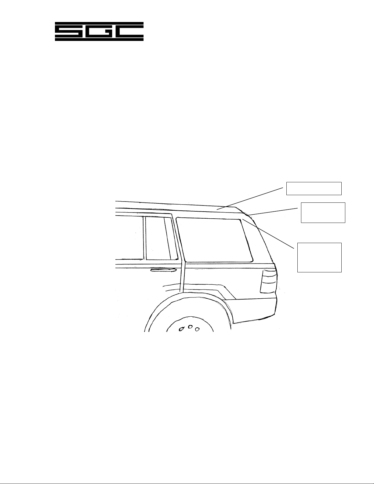
are shown below:
Proper Whip Installations
Roof Mounting
High on the
Rear Side
Panel
High on the
rear or trunk
Page 3

SG-303/307 WHIP ANTENNA MANUAL
© SGC 2007
INSTALLATION WITH AN ANTENNA COUPLER
The high voltage wire which connects the coupler to the antenna base must be at least 2 inches
away from any metal structure. Never tie wrap this wire to other wires or to a metal holder. If the
high voltage wire is not at least 2 inches away from any metal structure or wires, high voltage
arcing may occur, which will damage the coupler and subsequently the transmitter.
Mechanically the coupler can be installed in any position.
NOTE: Any excess high voltage wire between the antenna and the coupler must be
cut off before attaching the wire to the coupler. The ground wire should also be kept
as short as possible.
Coupler wiring through the body of the vehicle
IMPORTANT: The high voltage antenna wire must always be at least 2 inches away from any
metal structure.
The antenna must be unobstructed. Do not mount the antenna next to the metal body of the
vehicle. This will severely limit the radiation and the range of communication, and may cause the
antenna to arc and damage the coupler and transmitter.
The hole diameter for the high voltage and waterproof feed-through bushing is .890 inches. Install
the bushing in a location which allows the antenna to be lowered. Routing the RF coaxial cable
and the two wires for the 12 volt supply to the coupler is not critical. If necessary, the coupler can
be installed as much as 100 feet away from the radio. These wires can be tie wrapped to any
metallic or non-metallic point of the body structure.
Ratchet
Mount
8’
Coupler
Vehicle Body
High Voltage Wire
Power &
Coax Cable
RF Ground
Weatherproof
Feedthrough
Page 4

SG-303/307 WHIP ANTENNA MANUAL
© SGC 2007
Poor installation puts the lower part of the antenna next to the body of the car, minimizing
radiation and increasing losses, or puts it next to the engine compartment making noise more of a
problem.
Poor Installation Locations (front of vehicle)
Poor Installation Locations (rear of vehicle)
Antenna locations near the engine or that put a part of the antenna radiator below the level of the
body of the vehicle will radiate poorly and are not recommended.
Bumper
Mounts
Low Side
Panel Mounts
Front Bumper
Mounts
Front Side
Panel Mounts
Page 5

SG-303/307 WHIP ANTENNA MANUAL
© SGC 2007
INSTALLATION – VESSEL MOUNTING
In many cases, when a vessel is limited by space, a short and efficient antenna such as the SG-303
or the SG-307 is the best solution for good HF SSB performance. Choose an unobstructed section
of the boat to mount the antenna, as shown below.
Small Power Boat
SMALL BOAT WITH FISHING TOWER
The SG-303/307 whip can be mounted on top of the fishing tower. If this location is used, then the
coupler must also be mounted on top of the tower, preferably in a protected area.
Small Boat with Fishing Tower
The metal structure of the tower can be used as the ground for the coupler. Make sure that the
tower is grounded to the metal structures in the boat, such as the engine, railing, water tanks, etc. If
this is not possible, use at least three 20 foot ground straps to create an RF Ground system by
connecting them to the coupler RF Ground lug and to any metallic structures within the boat such
as the engine, railing, and water tanks.
Mount the antenna
HERE with the
coupler under the
deck
Mount the antenna here with the coupler as
close as possible
A possible
location for
the coupler
Make sure the tower is
adequately bonded to metal
structures inside the boat
Page 6

SG-303/307 WHIP ANTENNA MANUAL
© SGC 2007
SMALL METAL-HULLED SPEED BOAT
Use the metal structure of the boat for ground purposes. Follow the installation instructions of the
coupler and the SG-303/307 antenna as described for a vehicle installation.
SMALL FIBERGLASS-HULL SPEED BOAT
Mount the antenna on the bow. Use 3 ground straps laid in the bottom of the boat with the ends
tied on the engine ground to create a proper RF ground on your boat.
RF Grounding
All other metal structures in the vessel, such as the engine, railing, stove, metal fuel and water
tanks, etc. must be tied and bonded with the ground strap grounding system. In all cases never
install the antenna next to a metal structure; it must be at least 2 feet away. Always mount the
antenna above any metal structure to provide the best radiation and proper operation.
FINAL IMPORTANT NOTE
The SG-303/307 must be at least 4 feet away from any VHF, CB, GPS, Loran, or other antenna
system already existing on the boat or vehicle. Also clear rigging by 4 feet.
Antenna
Coupler
1-3” Ground Foil
Engines
 Loading...