


SG-239
Smartuner TM
Manual
Cat. #54-22
October 2001

SGC — The SSB People
SGC develops, manufactures, and sells high performance single sideband (SSB) communications equipment. Since 1971, the company has sold to the marine, military, aviation, and industrial markets worldwide. Over these years, SGC has earned an outstanding reputation for product reliability and for after sales service.
The company keeps pace with equipment options, engineering developments, and design requirements. Its products are the most competitive in the entire long distance communication market. SGC equipment is presently being used by the United Nations for inter-communications in developing countries throughout the world.
Many competitive racing vessels, as well as fishing boats, tugs, and commercial craft are equipped with SGC equipment. In fact, an SGC radiotelephone provided the only communications available on a past Polar expedition by the National Geographic Society.
SGC also supplies U.S. government agencies, several foreign governmental agencies, and major petroleum companies throughout Asia and Latin America.
All SGC equipment is designed and the USA. SGC has qualified peotechnical information, assisequipment, and recommenda-
for any installation.
SGC welcomes your call to discuss your SSB require-
ments.
|
Mailing: PO Box 3526, Bellevue, WA 98009 |
|
|
Shipping: 13737 SE 26th St., Bellevue, WA 98005 |
|
2 |
Toll-Free: 800-259-7331 • Phone 425-746-6310 • Fax: 425-746-6384 |
|
www.sgcworld.com • Email: sgc@sgcworld.com |
© 2001 SGC, Inc. |
|
Table of Contents
Specifications ………………………………………….. 5 1.0 Supplied Items ……………………………………… 6
2.0Mechanical Design …………………………………. 6
2.1Marine Mounting ……………………………………6
2.2Desert and High Temperature Installations …………6
2.3Direct Weather Protection Installations ……………. 7
3.0Coupler Configuration……...………………………..7
3.1Connections to SG-239………………………………7
3.2Tuning Process …………………………………….. 8
3.3Impedance Detector………………………………….8
3.4VSWR Detector…………………………………….. 9
3.5Phase Detector ……………………………………… 9
3.6Central Processing Unit (CPU) …………………….. 9
3.7Initialization………………………………………….10
3.8Jumper Settings…………………………………….. 10
4.0Tuning Process and Options ……………………….. 11
4.1Program Description ……………………………….. 11
4.2Tuning Paths ……………………………………….. 13 4.2.1 Antenna Too Short ……………………………….. 13 4.2.2 Antenna Too Long ……………………………….. 14 4.2.3 JP1—Tuning Elements Out During Receive………14 4.2.4 JP3—Tune From Memory ……………………….. 15
5.0B.I.T.E. Status LED Descriptions……………………15
6.0Optional SmartLock ……………………………….. 16
6.1Tune, Tune Lock, and Reset ……………………….. 17
6.2SmartLock Notes …………………………………… 17
7.0SG-239 Enhanced Features…………………………. 18
8.0Do-It-Yourself Light Bulb Dummy Load………….. 20
9.0Five Golden Rules of HF Installation ……………….22
10.0S t a n d a rd Warranty ……………………………..24
11.0Component Location………………………………. 25
12.0Schematics………………..……………………….. 26
13.0Smartuner™ Comparison Charts………………….. 34
This manual is produced as a guideline for the SG-239 antenna coupler. Performance and results may vary and SGC does not warrant any installation or any result.
This manual is subject to change without notice.

SG-239
Quick Start
Installation:
To quickly install your antenna coupler you will need the following:
1.An HF radio with 1.5 to 200 watts output.
2.An HF antenna with a wire feed. Minimum length of 9 feet (7-30 MHz @ 100W), 40 feet (3-30 MHz @ 200W) or 100 feet (1.8-30 MHz @ 100W).
3.A good ground radial longer than the antenna for the antenna and coupler.
4.+12 VDC and ground for the coupler. 5.SmartLock coupler controller (optional).
Power supply can be same as the radio or supplied by radio DC switch supply line.
Operation:
1. Turn on Radio. Apply +12 VDC power to the coupler. 2.As power is applied, coupler should make one “click”
sound and is in the bypass (un-tuned) state.
3.To tune, speak normally, whistle or use CW (CW is recommended).
4.Tuning should be done at full power for automatic. Clicking is heard.
5.When tuned, clicking stops, the tune LED turns on and output tune line goes low. SG-239 can be tuned manually at any transmit or receive frequency, five memory bins are assigned for receive only.
6.The coupler PI network can be manually tuned and stored in memory by using switch S1 and pushbuttons S2-S8.
|
Mailing: PO Box 3526, Bellevue, WA 98009 |
|
|
Shipping: 13737 SE 26th St., Bellevue, WA 98005 |
|
4 |
Toll-Free: 800-259-7331 • Phone 425-746-6310 • Fax: 425-746-6384 |
|
www.sgcworld.com • Email: sgc@sgcworld.com |
© 2001 SGC, Inc. |
|

Specifications SG-239
HF Frequency Range: |
1.8-30 MHz |
|
Power Input Range: |
1.5-200 watts (PEP) |
|
|
Or CW duty cycle 40% |
|
Number of channels: |
unlimited |
|
Revolving memory bins: 165 TX; 5 RX |
||
Input Impedance Range: .2-5000 ohms |
||
VSWR: |
(Typical) Typically less than 2:1 |
|
DC Input Requirement: +13.8 VDC (nominal) |
||
DC Operating Range: |
+10 to 18.5 VDC |
|
Input Current: Average: 230 milliamps |
||
Random set time: |
Typical: less than 2 seconds |
|
Recurrent set time: |
Typical: less than 10 milliseconds |
|
Antenna Length: |
Minimum length of 9 ft. - 7 to 30 MHz |
|
|
Minimum length of 40 ft.-3 to 30 MHz |
|
|
Minimum length of 100 ft. - 1.8-30 MHz |
|
Installation: |
Any position |
|
Operating Temperature: -35° to +70°C |
||
Size: |
7.5”L x 6”W x 1.85”H |
|
|
(19cm x 15cm x 4.5cm) |
|
Weight: |
2 pounds |
|
Case Construction: |
Irradiated aluminum case |
|
Control Cable |
Standard coaxial and 2 wires for DC plus 2 |
|
(not supplied) |
wires for optional SmartLock gauge 14-18 |
|
Antenna types: |
1. |
Whip |
|
2. |
Backstay (marine, sail) |
|
3. |
Dipole centerfed |
|
4. |
Dipole with feedline |
|
5. |
Loop (small) 2x2 multi turn |
|
6. |
Loop (large) 10 ft. and up single turn |
|
7. |
Longwire |
|
8. |
Ladder feed |
Specifications subject to change without notice.
1.0 Supplied Items
SG-239 Coupler
Manual
Quick-Start Card
2.0 Mechanical Design
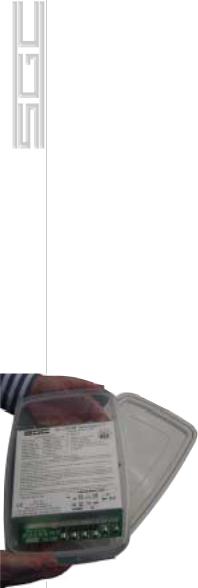
The SG-239 is supplied in an aluminum case with mounting holes. RF and DC power is supplied to the unit through terminals accessible on the outside of the case. The internal construction is designed to withstand the shock and vibration of marine service. Corrosionresistant hardware and passive alloys are employed throughout. For 99% of installations, the factory settings for jumpers will be correct. The coupler must be installed in an area not directly exposed to the sunshine or rain. Although the Smartuner is built very solidly, it is good installation practice to provide additional protection from the elements. SGC makes the following recommendations:
2.1 Marine Mounting
The Smartuner should be located inside the house or under the aft lazaret on a sailboat installed in a waterproof case. The preferred installation if vertical is with the RF terminals pointing upward. The antenna connects to the screws on the top. The SG-239 may be any position including inverted without any degradation of performance. To waterproof a SG239, place the unit in a sealable food con-
tainer, (1.7 liter - 7 cup standard size)
2.2 Desert and High Temperature Installations
Smartuner may be used in very hot clion a continuous basis if some additional from direct sunlight is provided and if installed in a waterproof case. Tempera-
a vehicle may exceed 212°F (100°C). It is keep the coupler in the shade if possible.
|
Mailing: PO Box 3526, Bellevue, WA 98009 |
|
|
Shipping: 13737 SE 26th St., Bellevue, WA 98005 |
|
6 |
Toll-Free: 800-259-7331 • Phone 425-746-6310 • Fax: 425-746-6384 |
|
www.sgcworld.com • Email: sgc@sgcworld.com |
© 2001 SGC, Inc. |
|
2.3 Direct Weather Protection Installations
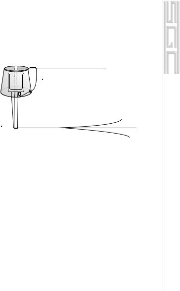
To protect the unit from direct exposure to sunlight and to prevent heavy build up of ice, we recommend installing the Smartuner first in a waterproof case then placing the case under some kind of protective housing. If you are mounting it on a tower in a hot or cold climate, a plastic wastebasket (such as those made by Rubbermaid™) makes an excellent weather cover and costs only a few dollars.
Long wire antenna
Smartuner mounted inside a plastic waste basket to protect it from extreme heat and heavy icing. This type of enclosure is widely available in all countries.
3.0 Coupler Configuration
Schematic Q30102900A, pg. 26, sheet 1 of 6, is the schematic diagram of the two basic coupler networks L & PI. Note that the L network as viewed from the generator, may be configured as either “C in” or “C out,” whichever is required by the load. In either case, the end of the network containing the shunt C element will be the higher impedance end of the network.
3.1 Connections to SG-239
Drawing G30102900A, pg. 26, sheet 1 of 6 and pg. 30, sheet 5 of 6, are the diagrams of the antenna coupler connections. RF input and ground is applied respectively to terminals “RF in” and GND.” The DC input is applied with the positive to the “12V” DC terminal and “GND DC.” The “TND” terminal can be connected to transceiver or SmartLock. This line cannot be connected to both units simultaneously. The Hold/Reset terminal is to be reconnected to the SmartLock option if used.
Mailing: PO Box 3526, Bellevue, WA 98009 |
|
Shipping: 13737 SE 26th St., Bellevue, WA 98005 |
|
Toll-Free: 800-259-7331 • Phone 425-746-6310 • Fax: 425-746-6384 |
7 |
www.sgcworld.com • Email: sgc@sgcworld.com |

3.2 Tuning Process
An array of detector devices in the SG-239 monitor the antenna system impedance, reactance signal, and the VSWR load when RF power is applied to the unit. The coupler also monitors forward power, since the control computer requires an indication of both forward and reflected power in order to allow tuning to proceed. The computer uses the forward power detector as a check to ensure that the measurements made are applied RF and are not spurious levels from the data conversion system. The SG-239 will proceed to tune only when enough forward power is present to confirm this check. After RF is applied to the detector system, it then passes through the coupler tuning array. The coupler tuning array consists of six capacitors in shunt on the input arm of the network, seven inductors in the series arm, and four more capacitors in shunt on the output arm, all arranged in binary increments. Relays are provided in conjunction with each lumped constant and allow removal or entry as desired. A network having 64 values on input shunt C, 16 values of output shunt C, and up to 128 values of series L is possible with the manipulation of these 17 relays.
3.3 Impedance Detector
RF transformers T1 and T3 drive the impedance bridge that is balanced at 50 ohms. T3 samples the line current and thus D7 out-puts a negative DC level proportional to line current. A tertiary winding on transformer T1 provides a line voltage sample to D2 that provides a positive voltage proportional to line voltage. R18 and R11 act as a summing network for the current and voltage signals, with ratios chosen, such that at 50 ohms, the summed signals result in a balanced or zero voltage condition. If the line impedance goes to high, the signal from the voltage sensor will be relatively higher than the current sensor, which will result in a net positive output voltage from the summing network. Similarly, a low line impedance will result in more output from the current sensor, resulting in a net negative output voltage from the summing network. The summing network output is shifted to a 0 to 5v range, then fed to the processor's A to D converter port, and used within the micro-controller.
|
Mailing: PO Box 3526, Bellevue, WA 98009 |
|
|
Shipping: 13737 SE 26th St., Bellevue, WA 98005 |
|
8 |
Toll-Free: 800-259-7331 • Phone 425-746-6310 • Fax: 425-746-6384 |
|
www.sgcworld.com • Email: sgc@sgcworld.com |
© 2001 SGC, Inc. |
|

3.4 VSWR Detector
A directional coupler is made up of a current transformer T2 and a voltage transformer T1, in conjunction with termination resistors R35, R36 and R33, R34. The coupler is inserted in the 50-ohm transmission line between the input connector, ST2 RF - ST3 GND, and the tuning network. The forward power is measured across termination R33, R34 and reflected power is measured across termination R35, R36. Diode D1 generates a positive DC voltage proportional to forward power and D3 generates a positive DC voltage proportional to reflected power. The forward DC output is fed to a voltage divider consisting of R19 and R14. These voltages are input to the RF power detector and to an A to D converter port of the processor. The reflected DC output passes through a voltage divider consisting of R29 and R16, and then it also goes to an A to D converter port of the processor.
3.5 Phase Detector
A phase detector is formed by T3, A1, and their associated components. This detector indicates the state of any reactance associated with the antenna coupler as noted from the generator. A line current sample is compared in phase with a voltage sample in a double balanced mixer. Output polarity varies negative or positive depending on the reactance of the antenna. The output of the phase detector A1 is shifted to a 0 to 5v range, then fed to the processor’s A to D converter port and used within the micro controller.
3.6 Central Processing Unit (CPU)
A tune-up algorithm, which is contained in the memory of the microprocessor, implements the antenna matching. It is designed around the MC68HC711E9 CPU that features a versatile instruction set, RAM, and EEPROM (memory which is saved after the coupler is turned off). The antenna coupler relays are controlled by latches U6 and U7, which receive serial data input directly from the CPU. During operation, data is transferred into the CPU from the A to D ports and Input Capture port (measures RF frequency). Basically, the program monitors the status of the input sensors and—starting from a preset condi- tion—uses a built-in algorithm to achieve a tuned condition. When the
Mailing: PO Box 3526, Bellevue, WA 98009 |
|
Shipping: 13737 SE 26th St., Bellevue, WA 98005 |
|
Toll-Free: 800-259-7331 • Phone 425-746-6310 • Fax: 425-746-6384 |
9 |
www.sgcworld.com • Email: sgc@sgcworld.com |

tuning algorithm is complete, the CPU saves the settings in its EEPROM, which is addressed by the applied RF frequency. This non-volatile memory table is the basis of the exclusive learning feature of the SG-239. After it has stored and latched the network status, the CPU waits for RF to cease transmitting and returns to the Stop mode. When RF is re-transmitted, the first step in the tuning algorithm is to measure the frequency of the signal passing through the coupler. From the frequency data, the computer then searches its EEPROM for previously stored data. If data is found, it is tested for validity, and the required “end of tune” conditions will be sensed by the RF sensors. Then the data will be latched in place, and the CPU will again wait for RF to cease transmitting and turn to the Stop mode. This process takes about 10 milliseconds, which is the same length of time that is required to close the network relays.
3.7 Initialization
The microcomputer is usually in the Stop mode and requires an interrupt signal (XIRQ) to start program implementation. The XIRQ is obtained from the RF detector circuitry. This line, going low, will wake the CPU from the Stop mode.
3.8 Jumper settings
The SG-239 may be bypassed for broad band (un-tuned antenna) scanning listening in receive mode. All you need to do is press the reset button of the SmartLock (if installed) or turn power to the coupler off and on. When the coupler comes back on, the tuning elements remain out of the circuit until the Smartuner is activated by a transmitted signal. If broad band operation is required during receive for scan operation, jumper JP1 may be set to the Yes position. This will drop the tuning elements out of the circuit on receive only. Jumper JP1 is located adjacent to MCU (U5) along the edge of the printed circuit board. Setting JP1 to the Yes position is recommended if you are using a radio for split band communications, for scanning selective calling protocols, or for Automatic Link Establishment (ALE). The default is: Tuning Out In Rcv: [NO].
Jumper JP3 bypasses the coupler's memories. This means that each time the coupler is used on a different frequency, it will re-tune
|
Mailing: PO Box 3526, Bellevue, WA 98009 |
|
|
Shipping: 13737 SE 26th St., Bellevue, WA 98005 |
|
10 |
Toll-Free: 800-259-7331 • Phone 425-746-6310 • Fax: 425-746-6384 |
|
www.sgcworld.com • Email: sgc@sgcworld.com |
© 2001 SGC, Inc. |
|
rather than use previously stored information. The default is: Tune From Memory: [YES].
4.0 Tuning Process and Options
MicroTune™ Software
Copyright 1991-2001
The SG-239 MicroTune™ Software is unique software which allows precise tuning of the digitally controlled π and L network to tune a wide variety of antennas. The versatile MicroTune™ software offers its user these special functions:
1.The coupler is activated whenever forward power is present.
2.In addition to sampling VSWR to determine if the coupler should re-tune, frequency comparison is employed. This causes the coupler to tune when ever the transmit frequency changes independent of the VSWR reading.
3.Extensive tuning paths are used to test different antenna situations. The initial tuning of a new frequency (or switched antenna) may require up to two seconds. Any further tuning is accomplished in a matter of milliseconds if jumper JP3 (Tune From Memory) is in its default position.
4.Facilities and algorithms are used which enable accurate tuning at the low end of the frequency band—even on shorter antennas than previously possible.
5.The BITE (Built-In-Test-Equipment) Indicator Tune LED includes a safety feature that alerts the operator to a mismatched condition, with blinking indicators, when proper tuning conditions have not been met. In this situation, the software will “time out” within 20 seconds unless a new frequency is sensed, which will cause an immediate time out, and the coupler will attempt to match the new frequency. The microprocessor of the coupler “wakes up” every time the coupler has forward power. However, re-tuning takes place only if the frequency has changed or the VSWR exceeds 2:1.
4.1 Program Description
When DC power is applied, the computer initializes the processor registers in accordance with the hardware. All tuning elements are then
Mailing: PO Box 3526, Bellevue, WA 98009 |
|
Shipping: 13737 SE 26th St., Bellevue, WA 98005 |
|
Toll-Free: 800-259-7331 • Phone 425-746-6310 • Fax: 425-746-6384 |
11 |
www.sgcworld.com • Email: sgc@sgcworld.com |
 Loading...