


SG-235
Smartuner®
Microprocessor Controlled Automatic Antenna Coupler
Installation and Operations Manual
Getting the most from every watt of HF-SSB Power

HF-SSB COMMUNICATIONS:
THE POWER TO LOCK IN THE WORLD.
Globally, HF-SSB has literally changed the world. For a minimal investment, it has allowed millions of people - often in amazingly remote settings, often in emergency conditions - to reliably bounce clear voice and data signals across a state, across a continent, over an ocean, or around the world. Without satellites, relay stations, cellular nets, stadium sized antennas or huge user fees. Just some fine equipment, a smart operator and nature's own ionosphere make this possible.
For nearly 30 years, the perfection of HF SSB has been the focus and the life of our company. Our efforts have not gone unnoticed. Today, SGC is a prominent choice of leading corporations, governments, relief agencies, paramilitary organiza-
tions, mariners, aviators, explorers, and scientists - all over the world. They trust our engineering and they value our experience.
A vital part of our company's strategy centers around new product development, with an emphasis on providing quality equipment which remains rugged, reliable and competitively priced. We are focused on providing customer service of the highest standard. Our commitment is to product training and comprehensive after sales support. Today, SGC is recog-
nized as a world class designer and manufacturer of HF SSB communications products.
At SGC we build communications power tools. Next generation HF-SSB radios, antennas, amplifiers and coupler systems that squeeze more range and clarity out of every watt of HF SSB communications power, are the technology and innovations that have helped SGC emerge as a cutting edge player in the expanding world of HF-SSB.
Actually, SGC was the first company to perfect and mass produce solid-state HF SSB radios, more than 20 years ago. Today, our focus is an ever higher level of HF SSB refinement and performance. All focused on creating HF SSB voice and data communications systems that are so user friendly
and so powerful, they allow every SGC user to easily lock in the world. SGC - HF SSB Power Tools!

SG-235 Manual
S G - 2 3 5
A N T E N N A
C O U P L E R
Installation and Operations Manual
Prepared: September 1998
CAUTION: Carefully read the “Quick Start” on the fol-
lowing page and all pertinent sections of this manual
prior to operating your Smartuner for the first time. This
unit will provide outstanding service if you follow the
detailed recommendations within this manual.
SGC Inc. SGC Building, 13737 S.E. 26th St. Bellevue, WA 98005 USA |
3 |
|
P.O. Box 3526, 98009 Fax: 425-746-6384 Tel: 425- 746-6310 or 1-800-259 7331 |
||
|
||
|
||
E-mail: sgc@sgcworld.com Web site: http://www.sgcworld.com |
© 1998 SGC Inc |
|
Manual |
|
|
Quick St |
uide |
Remote Manual Tuning |
|
To quickly install your antenna |
following: |
1.An HF radio installation with 3
2.An HF antenna with a single
Minimum length of 50 feet |
1.8 MHz). |
3.A good ground (counterpoise)
4.+12 VDC and ground for the
5.SmartLock PRO coupler
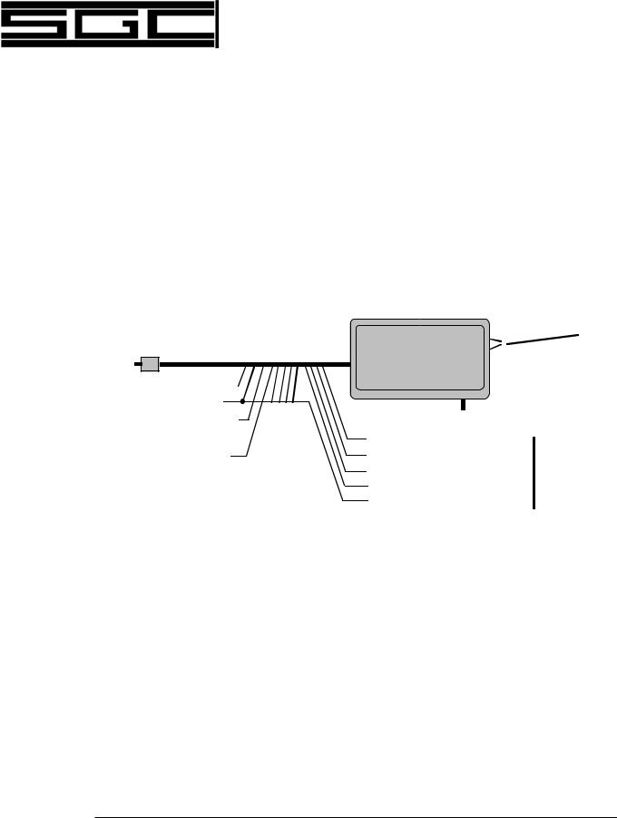
Connect the coupler to the system as |
diagram: |
|||
To transmitter/Amplifier |
Single wire |
|||
(3 to 500W) |
||||
|
|
|
||
|
|
|
||
|
|
|
|
|
RG 58
(To Linear Amp)
Black: DC Ground 
Red: +12 to 15 VDC
Gray: PTT Out to Linear (active low) *
Brown: PTT In from transceiver
Yellow: RS232
Purple: Receive 
Orange: Transmit
Blk/Wht: Ground
(TO RS232)
Antenna
Ground(Counterpoise)
Blue: Reset
White: Hold (Locks coupler settings)
Green: Tuned Indicator
Black/Yellow stripe: DC Ground
Red: +12 to 15 VDC
(TO SmartLock PRO)
12 conductor plus RG-58 coax
Optional connection not requred for normal use.
Operation:
1.Turn on radio. Apply +12 VDC power to the coupler.
2.As power is applied, coupler should make one ”click” sound. Coupler comes up in the bypass (untuned) state.
3.To tune, speak normally, whistle, or use CW (CW is recommended).
4.Tuning is done at a maximum of 100 watts. Once radio is tuned, the Gray wire transitions from 5V to GND and acts as a switch to turn on a 500W linear amplifier.
Note: Coupler must be used in manual PTT mode.
5.When tuned, clicking stops and Green wire goes low.
4 |
SGC Inc. SGC Building, 13737 |
S.E. 26th St. Bellevue, WA 98005 USA |
|
P.O. Box 3526, 98009 Fax: 425-746-6384 Tel: 425- 746-6310 or 1-800-259 7331 |
|
|
||
© 1998 SGC Inc |
E-mail: sgc@sgcworld.com |
Web site: http://www.sgcworld.com |

SG-235 Manual
Table of Contents
1.0 |
General information |
|
8 |
||
|
1.1 |
Experience Levels of Users |
8 |
||
|
1.2 |
What is an Antenna Coupler? |
8 |
||
|
1.3 |
Overall Description |
10 |
||
|
1.4 |
Coupler Network Configuration |
11S |
||
|
1.5 |
Operation Indicators |
11 |
||
|
1.6 |
Mechanical Configuration |
12 |
||
|
1.6.1 |
Marine Installation |
12 |
||
|
1.6.2 |
Desert and High Temperature Mounting |
13 |
||
|
1.6.3 |
Extremely Cold Temperatures |
13 |
||
|
1.7 |
Remote Installations |
14 |
||
|
1.8 |
Upgrade Sequences |
15 |
||
2.0 |
Specifications - SG-235 |
16 |
|||
|
2.1 |
Accessories |
|
16 |
|
3.0 |
Parts Furnished |
|
17 |
||
|
3.1 |
User Supplied Items |
17 |
||
|
3.2 |
Technical Support |
17 |
||
4.0 |
Antenna Types |
|
19 |
||
|
4.1 |
Selection |
|
20 |
|
|
4.2 |
Whip Antenna |
-2.5 - 3.0 METERS |
20 |
|
|
4.3 |
Whip Antenna |
- 7.0 -8.5 meter (23 ft) |
20 |
|
|
4.4 |
Longwire Antenna - 23 meter (75 ft) & 46 meter (150 ft) |
20 |
||
|
4.5 |
Backstay Antennas |
21 |
||
5.0 |
Typical Installations |
|
22 |
||
|
5.1 |
Apartment Loop Antenna |
28 |
||
|
5.2 |
Recreational Vehicle (RV) Antennas |
29 |
||
|
5.4 |
Aircraft Antennas |
30 |
||
|
5.5 |
Low Profile, Hidden and Covert Antennas |
31 |
||
|
5.5 |
Emergency Antennas |
32 |
||
|
5.6 |
Kite Antenna |
|
32 |
|
|
5.7 |
Tactical Installations |
33 |
||
|
5.8 |
Tactical Antenna Supports |
33 |
||
|
5.9 |
Tactical Grounds and Counterpoises |
34 |
||
|
|
|
|||
|
SGC Inc. SGC Building, 13737 S.E. 26th St. Bellevue, WA 98005 USA |
|
|||
|
5 |
||||
P.O. Box 3526, 98009 Fax: 425-746-6384 Tel: 425- 746-6310 or 1-800-259 7331 |
|||||
|
|||||
|
|||||
|
E-mail: sgc@sgcworld.com Web site: http://www.sgcworld.com |
© 1998 SGC Inc |
|||

|
|
SG-235 Manual |
|
|
|
|
|
6.0 |
General Notes on Antennas and Couplers |
34 |
|
|
6.1 |
Steps to Antenna Installation |
36 |
|
6.2 |
Antenna Location |
36 |
|
6.3 |
Ground Systems - General |
38 |
|
6.3.1 |
Vehicle Grounds |
38 |
|
6.3.2 |
Marine Grounds |
38 |
|
6.3.3 |
Base Station Grounds |
39 |
|
6.4 |
Corrosion |
40 |
|
6.5 |
Antenna Tuner Mounting |
41 |
|
6.6 |
Antenna Connection |
41 |
7.0 |
Installation Procedures |
42 |
|
|
7.1 |
Installation with SG-2000 |
42 |
|
7.2 |
Installation with SG-500 or other 500-watt amplifiers |
43 |
|
7.3 |
Smartlock Pro Installation |
43 |
|
7.4 |
Weatherdeck Mounting |
45 |
8.0 |
Electrical Checkout |
45 |
|
|
8.1 |
Alternate Electrical Checkout |
47 |
|
8.2 |
Coupler Configuration |
51 |
|
8.3 |
Tuning Process |
51 |
|
8.4 |
Impedance Detector |
52 |
|
8.5 |
VSWR Detector |
52 |
|
8.6 |
Phase Detector |
52 |
|
8.7 |
The Control Device (CPU -CENTRAL PROCESSING UNIT) |
53 |
|
8.8 |
Initialization |
53 |
|
8.9 |
Information Read |
54 |
|
8.10 |
Bypass Operation Jumpers |
54 |
9.0 |
Tuning Process and Options |
55 |
|
|
9.1 |
Program Description |
56 |
|
9.2 |
Tuning Algorithms or Paths |
57 |
|
9.3 |
Antenna Too Short |
58 |
|
9.4 |
Antenna Too Long |
59 |
|
9.5 |
J-2 - Tuning Elements out During Receive |
59 |
|
9.6 |
J-3 - Tune From Memory |
60 |
|
9.7 |
JP3PTT OUT CONTROL |
61 |
10.0 |
Smartlock PRO Opteration |
61 |
|
6 |
SGC Inc. SGC Building, 13737 |
S.E. 26th St. Bellevue, WA 98005 USA |
|
P.O. Box 3526, 98009 Fax: 425-746-6384 Tel: 425- 746-6310 or 1-800-259 7331 |
|
|
||
© 1998 SGC Inc |
E-mail: sgc@sgcworld.com |
Web site: http://www.sgcworld.com |

SG-235 Manual
10.1 |
Tune, Tune Lock, and Reset |
61 |
10.2 |
Smartlock PRO Notes |
61 |
Quick Start Guide - Remote Manual Tuning |
62 |
|
11.0 Troubleshooting the SG-235 - General |
63 |
|
11.1 |
Ground Faults |
63 |
11.2 |
Antenna Faults |
64 |
11.3 |
Transmitter Faults |
66 |
11.4 |
A Final Pointer on Troubleshooting |
67 |
Warranty Information |
68 |
|
Schematics |
|
|
Appendix - QMS System
QMS Brochure
SG-500 SmartPowerCube Brochure
SGC Inc. SGC Building, 13737 S.E. 26th St. Bellevue, WA 98005 USA |
7 |
|
P.O. Box 3526, 98009 Fax: 425-746-6384 Tel: 425- 746-6310 or 1-800-259 7331 |
||
|
||
|
||
E-mail: sgc@sgcworld.com Web site: http://www.sgcworld.com |
© 1998 SGC Inc |

SG-235 Manual
1.0 General Information
The Smartuner™ reputation has grown to legend status because it is simple to use and highly reliable. A Smartuner will provide maximum transfer of radio energy from any HF transmitter to any end-fed HF antenna within the frequency and power limits of its specifications. The SG-235 is a high-powered cousin of the SG-230PRO. It provides many of the same features: a new microcontroller which has built-in A/D functions, non-volatile memory, and serial communications capabilities which allow manual tuning using an RS-232 connection and PC. The optional RS-232 should be used only for special applications and is not necessary if used in normal applications.
This document is designed to guide the SG-235 user through installation and operation of the unit. This document will also recommend various steps which may be undertaken in the field to provide correct operation of the SG-235 should difficulty be encountered. Smartuners are extraordinarily reliable. But you should be aware that scores of fine points to any HF installation can easily be overlooked and may cause difficulty. This manual should help you quickly to obtain the best possible performance from your HF radio installation and to avoid most of the pitfalls which can degrade the performance of your HF system.
1.1 Experience Levels of Users
The Smartuner™ may be installed successfully by anyone who follows the instructions in this manual. However, if you are inexperienced in HF radio installation and operation, seeking advice from people with more experience will help you achieve good results quickly and with minimum frustration. Even the most experienced professional HF users will occasionally run into difficulty.
Regardless of the level of your experience, SGC stands ready to offer you installation suggestions and to help you resolve any aspect of Smartuner™ operation which is not entirely satisfactory. If you have a specific question, please send us a fax at our Bellevue, Washington (USA) headquarters. The number is (425) 746-6384. If you require telephone assistance, please call us at (425) 746-6310 during business hours, 8:00 A.M. to 5:00 P.M. Pacific Time.
1.2 What Is an Antenna Coupler?
Antenna “couplers” are placed at the antenna and match conditions of the antenna to the feed line in a very precise manner. Antenna “tuners,” on the other hand, are generally located at the transmitter output end of the coaxial feed line. Do not be confused by the term “coupler” and “tuner.”
8 |
SGC Inc. SGC Building, 13737 |
S.E. 26th St. Bellevue, WA 98005 USA |
|
P.O. Box 3526, 98009 Fax: 425-746-6384 Tel: 425- 746-6310 or 1-800-259 7331 |
|
|
||
© 1998 SGC Inc |
E-mail: sgc@sgcworld.com |
Web site: http://www.sgcworld.com |

SG-235 Manual
•A tuner placed at the transmitter loads up the feedline as well as the antenna (so that the feedline radiates).
•A coupler installed at the antenna eliminates feed line losses by providing a proper match of the antenna to the feed line. The Smartuner is a true antenna coupler.
We will emphasize these key points throughout this manual to yield the best
possible operation of your Smartuner. These include:
•The coupler must be located at the antenna.
•No coax may be connected to the coupler output.
•The coupler must have clean 12 VDC power supplied to it.
•The ground system must always be larger than the antenna.
•The antenna wire should be of the largest gauge practical.
•Capacitance at the coupler output must be minimal.
•The antenna must be of sufficient length for your lowest operating frequency.
Strictly observing these basic rules will ensure good operations under the
widest range of conditions.
PLEASE MAKE NOTE OF THE FOLLOWING INFORMATION FOR YOUR RECORDS:
Date unit was Purchased: _______/_______/_______
Dealer from whom purchased: ____________________________
Date installed: _______/_______/_______
Type of antenna used: ___________________________________
SGC Inc. SGC Building, 13737 S.E. 26th St. Bellevue, WA 98005 USA |
9 |
|
P.O. Box 3526, 98009 Fax: 425-746-6384 Tel: 425- 746-6310 or 1-800-259 7331 |
||
|
||
|
||
E-mail: sgc@sgcworld.com Web site: http://www.sgcworld.com |
© 1998 SGC Inc |

SG-235 Manual
1.3 Overall Description
The SG-235 is a general purpose coupler which can operate with any type of HF radio and almost any type of antenna configuration. The coupler network configuration is of a ¹ or L type; sensors continually monitor the state of the
tuning and relay this information to the processor.
Tune. The initial (first time) tuning may take several milliseconds to a few seconds depending on the complexity of the tuning process for a specific antenna configuration. After tuning the first time for a specific frequency and antenna, this information is entered in the nonvolatile computer memory, which will store up to 170 tuning solutions.
Retune. When the same conditions are encountered again, re-tuning is accomplished within 10 milliseconds by recalling the information from the nonvolatile memory. Special software designed by SGC assures accurate and fine tuning of the coupler. For software description, refer to the MicroTune™ section (9.0) of the manual.
If antenna or transmitter conditions have changed since the information was stored in memory, SG-235 retunes and achieves a new tuning solution. This new information is stored to memory for future reference. Important: the Smartuner™ will always look for the best possible tuning solution and will improve existing tuning solutions whenever possible.
The SG-235 may be bypassed and your antenna used as a broadband receiving antenna. To do this, turn off the power to the coupler for two seconds and then turn it back on (or simply press the reset button on the SmartLock Pro). The coupler is now reset to stand-by, waiting for the first RF power to be transmitted before providing a tuning solution. In the stand-by mode, the antenna bypasses tuning elements and connects directly to the receiver with no tuning elements engaged, allowing reception of signals throughout the HF range.
The coupler will cease to operate normally if input voltage drops below 10.5 VDC
•if a marginal battery is used, or
•if you are transmitting at high power with an inadequate power supply or battery.
Batteries must be fully charged for proper operation. Large gauge wiring to
the transmitter and coupler must be used to avoid retuning.
10 |
SGC Inc. SGC Building, 13737 |
S.E. 26th St. Bellevue, WA 98005 USA |
|
P.O. Box 3526, 98009 Fax: 425-746-6384 Tel: 425- 746-6310 or 1-800-259 7331 |
|
|
||
© 1998 SGC Inc |
E-mail: sgc@sgcworld.com |
Web site: http://www.sgcworld.com |
SG-235 Manual
If broadband operation is required during scanning operations, jumper JP-2 on the printed circuit board inside the coupler may be set to the “YES” mode. This will bypass tuning elements on Receive. Jumper JP-2 is located adjacent to the shield along the edge of the printed circuit board.
In some cases, it may be desirable to re-tune the coupler and bypass the memory information. If you wish to bypass the recalled tuning solutions, place jumper JP-1, also located near U2, to the “NO” position.
Note: The SG-235 can be forced to retune in every new frequency, even if JP-1 is set to “Yes,” by the following operations of the Smartlock:
1.Engage “Tune lock.”
2.Press Reset once.
3.Disengage “Tune lock.” (See Section 9.2.)
1.4Coupler Network Configuration
The coupler network configuration is designed with 64 different input capacitor values, 32 output capacitor values, and 256 inductor values, thus providing about a half million different ¹ or L configurations. The coupler requires an
input of 5 to 500 watts to operate.
1.5 Operation Indicators
Operational status of the coupler and the onboard computer’s tuning decisions is displayed by five LEDs, which are located on the microcontroller unit (MCU) printed circuit board (PCB). These indicators are visible only when the cover of the coupler is removed. These five LEDs are not designed to be interpreted by other than factory and trained service personnel.
SGC Inc. SGC Building, 13737 S.E. 26th St. Bellevue, WA 98005 USA |
11 |
|
P.O. Box 3526, 98009 Fax: 425-746-6384 Tel: 425- 746-6310 or 1-800-259 7331 |
||
|
||
|
||
E-mail: sgc@sgcworld.com Web site: http://www.sgcworld.com |
© 1998 SGC Inc |

SG-235 Manual
CAUTION:
Dangerous high voltages exist inside the Smartuner when it is operated with an HF transmitter. High RF voltages in excess of 10 kv may be expected in normal operation of this unit. In addition to shock hazard, these RF voltages may produce burns which are very painful if you come in contact with exposed components. Therefore, DO NOT operate without the cover secured in place unless you are a well experienced radio technician or engineer.
As a matter of good installation and engineering practice, exposed metal antenna elements should be located in such a manner as to prevent accidental contact with people (especially young children), pets, and small animals.
1.6 Mechanical Design
The SG-235 is supplied in a weather proof case with two mounting brackets. RF and DC power are supplied to the unit through the same cable. This special cable comprises a 50-ohm coaxial cable and 12 conductors. The 12 conductor wires include the ground, the positive power lead, the optional SmartLock control, and the optional LED indicator.
The SG-235 antenna coupler’s weatherproof case will withstand the environmental conditions encountered aboard ship when mounted on a weatherdeck. The internal construction is designed to withstand the shock and vibration of marine service. Corrosion-resistant hardware and passive alloys are employed throughout.
We do not recommend opening the Smartuner case unless it is necessary. For 99% of installations, the factory settings for jumpers will be correct. Should you have occasion to open the case, use care to ensure the sealing gasket is placed properly to maintain watertight integrity of the unit.
Although the Smartuner is solidly built, good installation practice calls for additional protection from the elements.
SGC makes the following recommendations:
1.6.1 Marine Mounting
The Smartuner should be located inside the house or under the aft lazaret on a sailboat. On power boats, the coupler may be mounted outside, but additional
12 |
SGC Inc. SGC Building, 13737 |
S.E. 26th St. Bellevue, WA 98005 USA |
|
P.O. Box 3526, 98009 Fax: 425-746-6384 Tel: 425- 746-6310 or 1-800-259 7331 |
|
|
||
© 1998 SGC Inc |
E-mail: sgc@sgcworld.com |
Web site: http://www.sgcworld.com |

SG-235 Manual
protective housing is recommended. The preferred installation if vertical is with the standoff insulator pointing upward.
A stuffing gland for the RF and DC cables is provided on the lower edge of the weather housing, along with a 1/4-20 stainless steel ground stud. The antenna connects to the ceramic insulator on top of the weather housing.
The SG-235 may be mounted in any position, including inverted, without any degradation of performance. If the coupler is to be exposed to long periods of high vibration, such as aboard helicopters or tug boats, installation of the optional shock mounting is recommended.
1.6.2 Hot climate and High Temperature Installations
The Smartuner may be used in hot climates on a continuous basis if some additional protection from direct sunlight is provided. The best protection for a mobile installation is provided by the QMS (Quick Mounting System) which keeps the antenna coupler outside of a vehicle. Temperatures inside a vehicle may exceed 212°F (100° C). If a QMS is not used, keep the coupler in the shade if possible. Please refer to the diagram in the following section.
1.6.3 Extremely Cold Temperature Installations
Your Smartuner will operate down to specified temperatures. We recommend placing the Smartuner under some kind of housing other than the case to prevent heavy build up of ice. If you are mounting on a tower in an extreme climate, a plastic wastebasket (such as those made by Rubbermaid™) makes an excellent weather cover and costs only a few dollars.
Long wire antenna
Smartuner mounted inside a plastic waste basket to protect it from extreme heat and heavy icing. This type of enclosure is widely available in all countries.
SGC Inc. SGC Building, 13737 S.E. 26th St. Bellevue, WA 98005 USA |
13 |
|
P.O. Box 3526, 98009 Fax: 425-746-6384 Tel: 425- 746-6310 or 1-800-259 7331 |
||
|
||
|
||
E-mail: sgc@sgcworld.com Web site: http://www.sgcworld.com |
© 1998 SGC Inc |

SG-235 Manual
1.7 Remote Installations
The SG-235 is supplied with a standard 25 feet of cable.
If necessary, the coupler can be installed up to 100 feet from the transmetter. However, SGC does not recommend installing the Smartuner more than 100 feet from the transmitter because two losses must be considered.
• The first loss in long distance installations is normal attenuation of the radio signal coming from the transmitter to the antenna via the coax. (The longer the coaxial cable run, the higher the loss.) The amount of loss depends on frequency. At 2 MHz, the loss is approximately .5 dB, while at 30 MHz the loss in 100 feet of coaxial cable is over 2 dB. (A 100 watt transmitter at 30 MHz would actually deliver about 70 watts to the antenna after running through 100 feet of coax.)
If you are seeking the utmost performance at 30 MHz and you cannot avoid a run of 100 feet, or longer, we recommend using a larger low-loss type of coax such as RG-8 (foam dielectric) or Belden type 9943 coax. Both of these will reduce attenuation to under 1 dB per 100 feet at frequencies below 30 MHz. You should be aware that this heavier cable is less easy to work and may be quite expensive.
• The second loss which must be considered is that in the DC power and reset control line. At any distance other than the 25 foot cable which is supplied by SGC, we recommend that the DC voltage at the antenna coupler be measured. (If the coupler voltage drops below 10 volts, the coupler may not operate properly.) For this reason, SGC recommends that if distances are great, the input DC voltage at the transmitter site be adjusted to provide for +12 to +14 volts at the coupler site.
We do specifically advise against use of a different power supply than the one used to power the radio because of the danger of creating ground loops. Ground loops may cause oscillation of the final amplifiers or other undesired side effects. If you decide to use a separate power supply mounted at the antenna coupler location, please be advised that SGC does not provide technical support in this area.
14 |
SGC Inc. SGC Building, 13737 |
S.E. 26th St. Bellevue, WA 98005 USA |
|
P.O. Box 3526, 98009 Fax: 425-746-6384 Tel: 425- 746-6310 or 1-800-259 7331 |
|
|
||
© 1998 SGC Inc |
E-mail: sgc@sgcworld.com |
Web site: http://www.sgcworld.com |

SG-235 Manual
1.8 Upgrade Sequence
The current version of the SG-235 coupler will have a revision letter located on the printed circuit board. To continue moving forward in coupler design, the SG-235 may be revised as needed. Later revisions of the coupler will be denoted by the subsequent letters of the alphabet. The SG-235 contains all the latest revisions of the standard SG-230PRO to ensure the user is acquiring all the benefits of the SG-230PRO along with the added benefits of the SG-235.
SGC will continue making incremental improvements in the Smartuner product. When you buy your product today and a new feature is added, you can always upgrade for modest fees to the latest version of the unit. If you would like to upgrade to the latest version of the unit, contact SGC because special discounts are always provided to our valued customers.
SGC Inc. SGC Building, 13737 S.E. 26th St. Bellevue, WA 98005 USA |
15 |
|
P.O. Box 3526, 98009 Fax: 425-746-6384 Tel: 425- 746-6310 or 1-800-259 7331 |
||
|
||
|
||
E-mail: sgc@sgcworld.com Web site: http://www.sgcworld.com |
© 1998 SGC Inc |

SG-235 Manual
2.0 Specifications - SG-235
HF Frequency Range: |
1.8 to 30.0 MHz |
Note: The SG-235 may be operated as low as 1.6 MHz and is commonly used as an antenna matching unit for differential GPS transmitter site antennas. However, when operated under these conditions, a longer antenna is recommended, such as a 360 foot tower section for operation in the 1700-1710 kHz band and an appropriately larger counterpoise. In addition, inductor heating may become pronounced at high power levels in the SG-235’s inductors that are commonly used at these frequencies. To extend your frequency range, we recommend 350 watts at 1700 kHz and 250 watts at 1600 kHz on a continuous basis.
Power Input Range: |
3 to 500 watts (PEP) |
Input Impedance Range: |
45 to 55 ohms |
VSWR: (Typical) |
Typically less than 1.4:1 |
DC Input Requirement: |
+13.6VDC |
DC Operating Range: |
+10.5 to+15VDC |
Input Current: |
Average: .9 amps |
Random set time: |
Typical: less than 2 seconds |
Recurrent set time: |
Typical: less than 10 milliseconds |
Antenna Length: |
Minimum length of 50 ft. —3.0 to 30 MHz |
|
Minimum length of 300 ft. —1.8 to 30 MHz |
|
SG-303—9 feet from 3.5 to 30MHz |
Installation: |
Any position |
Operating Temperature: |
-35° to +70°C |
Size: |
16 x 12 x 3 inches |
Weight: |
8 pounds (3.5 kilos) |
Case Construction: |
Plastic ABS weatherproof case |
Control Cable: |
SGC special cable, 25 ft. coaxial and 12 interconnect wires |
|
(replaceable by any standard cable plus remote tune LED wire) |
2.1 Accessories
Shock Mounting Tray. SGC Part Number 54-50
16 |
SGC Inc. SGC Building, 13737 |
S.E. 26th St. Bellevue, WA 98005 USA |
|
P.O. Box 3526, 98009 Fax: 425-746-6384 Tel: 425- 746-6310 or 1-800-259 7331 |
|
|
||
© 1998 SGC Inc |
E-mail: sgc@sgcworld.com |
Web site: http://www.sgcworld.com |

SG-235 Manual
3.0Parts Furnished (unpacking)
Antenna Coupler
25 foot special cable (RG-58 plus 12 conductors in a single jacket)
Instruction Manual
SmartLock PRO coupler controller with 25 foot cable.
3.1User Supplied Items
The user of the SG-235 will need to supply a suitable HF radio antenna. Such an antenna may be as simple as an 23 foot long piece of wire and several ground/counterpoise radials of 23 feet or longer. The longer the antenna, up to about 300 feet, the better all around performance will be. Longer antennas may be used, but please refer to sections on antennas limitations.
The user will also have to supply a good counterpoise. Such a counterpoise is a large metal surface (much larger electrically than the antenna). Generally, the bigger the counterpoise, the better your signal will be.
3.2Technical Support
Before contacting SGC for technical support, please take a few minutes to think through your installation and ask if there is anything obvious which you have overlooked in the installation. Check to make sure your ground system is both adequate and tight and that proper voltage is supplied to the coupler.
In the event you experience difficulty with your SG-235 antenna coupler, you should contact SGC for technical advise. Before calling, we ask you to have the following information ready so that we may readily assist you.
Coupler Information Please have the serial number of your coupler,
the name of the dealer from whom the unit was purchased and the approximate date of purchase.
A n t e n n a I n f o r m a t i o n Please be ready to describe your antenna installation. You will need to advise us whether the antenna is a wire type, a dipole, vee, vertical, long wire or whip antenna.
Ground System You should be ready to describe your ground system in
SGC Inc. SGC Building, 13737 S.E. 26th St. Bellevue, WA 98005 USA |
17 |
|
P.O. Box 3526, 98009 Fax: 425-746-6384 Tel: 425- 746-6310 or 1-800-259 7331 |
||
|
||
|
||
E-mail: sgc@sgcworld.com Web site: http://www.sgcworld.com |
© 1998 SGC Inc |

SG-235 Manual
detail. If you are dealing with a marine installation, you should have a description of the vessel's bonding system. If you are using the coupler in a mobile setting, you should be able to describe bonding of the hood, trunk and other vehicle parts which may have been done. In an aircraft, you should be able to describe the location of the coupler and the type of ground connection used.
P o w e r s u p p l y v o l t a g e One of the common mistakes made when
installing couplers is to assume that a connection is good when it hasn't been measured. If you experience any type of erratic or intermittent operation, please measure the power supply voltage inside the coupler.
Describe Tuner behavior If you are having a problem, determine if it is happening all the time or only part of the time. Does the problem occur only on certain frequencies? Does the problem only happen in certain modes? This type of information is extremely useful in quickly isolating your problem.
Be patient Finding the reason for less than ideal system operation may take one telephone call or it may take several calls. Regardless of how complex the problem is, your SGC representative will be able to walk you through the process of solving your problem in a logical step-by-step manner. There is nothing magic about HF. Although it may seem so at times, the rules of physics don't change. The Smartuner and accessories will always give top performance when carefully installed.
18 |
SGC Inc. SGC Building, 13737 |
S.E. 26th St. Bellevue, WA 98005 USA |
|
P.O. Box 3526, 98009 Fax: 425-746-6384 Tel: 425- 746-6310 or 1-800-259 7331 |
|
|
||
© 1998 SGC Inc |
E-mail: sgc@sgcworld.com |
Web site: http://www.sgcworld.com |

SG-235 Manual
4.0Antenna Types Recommended Antennas
SG-105 - Marine and Base station antenna. This is a 60-foot end-fed long wire type antenna. SGC Part Number 55-10.
SG-114 - Base station antenna. 200 feet
SGC Part Number 55-14
SG-203 - Marine 28-foot whip antenna. This antenna is used for most power boat installations. SGC Part Number 55-23.
SG-303 - High performance 9-foot whip antenna. This dual element antenna is designed for severe marine and land mobile service. SGC Part Number 55-27.
QMS-3 - Quick Mounting System which houses SG-235 Smartuner and also provides a sturdy mounting platform for the SG-303 antenna system. Designed for rapid installations requiring no-holes installation of high performance HF antenna system. SGC Part Number 55-48.
The automatic antenna tuner is designed for use with end-fed unbalanced antennas such as whips and long wires. The radiating portion of the antenna is connected directly to the tuner through a high voltage insulator. It is extremely important that the antenna type, site location and grounding technique be correctly chosen so that the system will radiate effectively.
Broadband resonant antennas (e.g. log periodic) that cover the full range of the system may be used with the tuner if desired. Narrow band resonant antennas, such as dipoles, vee's and inverted vee's may only be used if the antenna VSWR (including coaxial feeder) is less than, or equal to 3:1 at the operating frequency.
Note that if a dipole or Vee type antenna; is used, the antenna may be operated at any frequency within the range of the coupler if each side of the vee or dipole is 23 feet or longer. In addition, the SG-235 is just as happy feeding
SGC Inc. SGC Building, 13737 S.E. 26th St. Bellevue, WA 98005 USA |
19 |
|
P.O. Box 3526, 98009 Fax: 425-746-6384 Tel: 425- 746-6310 or 1-800-259 7331 |
||
|
||
|
||
E-mail: sgc@sgcworld.com Web site: http://www.sgcworld.com |
© 1998 SGC Inc |

SG-235 Manual
a conventional Vee antenna as an inverted Vee. The coupler is very flexible in this regard.
4.1Antenna Selection
The automatic antenna tuner will operate into almost any end fed antenna with a length of 2.5 meters or more, provided an effective ground is used. The antenna efficiency will be proportional to length and in most applications will be maximum at a length of 1/4 wavelength. This means that the longest possible antenna should be selected for each installation.
Very short antennas are only recommended when there is no other alternative such as in a vehicular mobile installation. The performance of short whip antennas is usually very poor, particularly at the lower frequencies, and radiation efficiency will be only a few percent of a full sized antenna. However, a special electrically long antenna such as the SG-303 9 ft. mobile antenna overcomes much of the radiation problem.
4.2Whip Antennas - 2.5-3.0 meters (8-9 ft)
This antenna is recommended only for vehicular mobile installations. The short length will result in poorer performance when compared with the longer antennas. A special high performance 9 foot antenna, the SG-303, is manufactured by SGC specifically for this problem. The SG-303 is SGC Part Number 55-27.
4.3Whip Antenna - 7.0 to 8.5 Meter (28 ft)
This antenna is recommended for marine installation on smaller vessels. It may also be used in base stations if there is no way of using a longer antenna. The SG-203 is this type of antenna. Order SGC Part Number 55-23.
4.5Longwire Antenna -
23 meter (75 ft) and 46 meter (150 ft)
For most applications the longwire antenna will give the best results and is recommended when practical. The diagrams at the end of this section show some recommended methods of installation. These are only a few of the many possible methods of installation and frequently a different configuration will be the best at a particular site. SGC's long wire antenna, 60 feet in length, provides efficient operation on low frequencies and high frequencies alike. Order SGC Part Number 55-10.
20 |
SGC Inc. SGC Building, 13737 |
S.E. 26th St. Bellevue, WA 98005 USA |
|
P.O. Box 3526, 98009 Fax: 425-746-6384 Tel: 425- 746-6310 or 1-800-259 7331 |
|
|
||
© 1998 SGC Inc |
E-mail: sgc@sgcworld.com |
Web site: http://www.sgcworld.com |
SG-235 Manual
Antenna Length vs. Lowest Tunable Frequency
Antenna Length |
Lowest Frequency |
in Feet (approximate) |
in KHz |
350 feet |
1650 KHz |
335 feet |
1700 KHz |
315 feet |
1800 KHz |
285 feet |
1900 KHz |
275 feet |
1950 KHz |
220 feet |
2000 KHz |
100 feet |
2500 KHz |
50 feet |
3000 KHz |
4.6Backstay Antennas -
8 meters (28 ft) and longer
Although we would love to sell everyone a high performance marine whip
antenna, the backstay of a sailboat is almost impossible to improve upon in
most installations.
SGC Inc. SGC Building, 13737 S.E. 26th St. Bellevue, WA 98005 USA |
21 |
|
P.O. Box 3526, 98009 Fax: 425-746-6384 Tel: 425- 746-6310 or 1-800-259 7331 |
||
|
||
|
||
E-mail: sgc@sgcworld.com Web site: http://www.sgcworld.com |
© 1998 SGC Inc |

SG-235 Manual
5.0Typical Installations
Figures 5.01 through 5.3.1 show some typical installations for the automatic
antenna tuner.
Figure 5.01 Jeep Installation
|
|
|
|
|
|
|
|
|
|
|
SG-303 whip |
||
Jeep Installation |
|
|
|
|
|
|
|
|
2.0 M whip |
||||
|
|
|
|
|
|
|
|
|
|
|
|||
for Automatic |
|
|
|
|
|
|
Detail |
||||||
Antenna Coupler |
|
|
|
|
|
|
|
||||||
|
|
|
|
|
|
|
|
|
|
|
Transceiver |
||
|
|
|
|
|
|
|
|
|
|
|
|
|
|
|
|
|
|
|
|
|
|
|
|
|
|
|
|
|
|
|
|
|
|
|
|
|
|
|
|
|
|
|
|
|
|
|
|
|
|
|
|
|
|
|
|
|
|
|
|
|
|
|
|
|
|
|
|
|
|
|
|
|
|
|
|
|
|
|
|
|
|
|
|
|
|
|
|
|
|
|
|
|
|
|
|
|
|
|
|
|
|
|
|
|
|
|
|
|
|
|
|
|
|
|
|
|
|
|
|
|
|
|
|
|
|
|
|
|
|
|
|
|
|
|
|
|
|
|
|
|
|
|
|
|
|
|
|
|
|
|
|
|
|
|
|
|
|
|
|
|
|
|
|
|
|
|
|
|
Coupler |
|
Feed-through |
GTO cable |
|
(as short as possible) |
||
insulator |
||
|
Figure 5.02 Vehicle installation
Ground |
2SG.0 M-303whipwhip |
coupler |
|
securely |
Feed through insulator |
to truck |
|
Coupler |
|
Transceiver |
|
|
|
Vehicle Installation |
|
|
|
|
|
|
|
22 |
SGC Inc. SGC Building, 13737 S.E. 26th St. Bellevue, WA 98005 USA |
|
|
P.O. Box 3526, 98009 Fax: 425-746-6384 Tel: 425- 746-6310 or 1-800-259 7331 |
|
|
|
|
© 1998 SGC Inc |
E-mail: sgc@sgcworld.com Web site: http://www.sgcworld.com |

SG-235 Manual
Figure 5.03 Motor Vessel installation
Feed through insulator
Coupler
Suitable stay cable
Ground to steel bulkhead or overhead
Motor Vessel Installation
Figure 5.04 |
Base installation |
7M to 10M |
GROUND LEAD |
1.5M MAX |
 GROUND ROD (3M)
SGC Inc. SGC Building, 13737 S.E. 26th St. Bellevue, WA 98005 USA |
23 |
|
P.O. Box 3526, 98009 Fax: 425-746-6384 Tel: 425- 746-6310 or 1-800-259 7331 |
||
|
||
|
||
E-mail: sgc@sgcworld.com Web site: http://www.sgcworld.com |
© 1998 SGC Inc |

SG-235 Manual
Figure 5.05 Base installation with ground wire radials
|
|
pole or tree supports far end |
|
|
|
|
Insulator |
|
|
11M |
2M |
|
|
|
|
30° |
|
|
|
Insulator |
|
|
|
GTO cable |
|
|
30° |
|
|
|
|
Coupler |
|
|
|
2M |
|
|
Radial wires |
|
|
|
|
Ground cable No. 4 AWG |
|
buried in soil |
|
(150 cm maximum) |
|
|
|
|
Base Installation with |
||
Conduit for |
Ground Wire Radials |
||
control cable |
|
|
|
and coax
Figure 5.06 Base dipole installation
1 m e t e r |
||
3 meters |
||
|
E 6 6 i n s u l a t o r s |
|
Hot |
( x 8 ) |
|
7 to 25 meters |
||
G N D |
||
Coupler
 3 meters
RF Cable |
Control cable |
Base Dipole Installation
24 |
SGC Inc. SGC Building, 13737 |
S.E. 26th St. Bellevue, WA 98005 USA |
|
P.O. Box 3526, 98009 Fax: 425-746-6384 Tel: 425- 746-6310 or 1-800-259 7331 |
|
|
||
© 1998 SGC Inc |
E-mail: sgc@sgcworld.com |
Web site: http://www.sgcworld.com |

SG-235 Manual
Figure 5.07 Base Quadra Loop Horizontal
Radiation
Porcelain isolators with tie rope
Coupler
Ground bolt terminal
Antenna 50 ohm terminal coax from
transmitter
Base Quadra
Loop Horizontal
The horizontal quad loop is a groundless antenna for high angle radiation and is ideal for HF communications from zero to 500 miles in the frequency range of 2 to 10 MHz. This configuration provides optimum near-right angle reflection to the ionosphere for short range communications.
A square base can be from 8 to 15 meters long and can be configured to the shape of the structure as necessary, to provide the best arrangement. The height of the supporting poles should be 20 to 40 feet. Supporting poles should be as tall as possible to provide the antenna with the greatest isolation from industrial noise generated by the building, such as fluorescent lights and electrical motors. Loop antennas are also less susceptible to industrial RF noise generated by the building, because they are isolated from the ground system of the building.
Loop wires are attached at one end on the high voltage active side of the coupler and on the other end at the ground side of the coupler.
SGC Inc. SGC Building, 13737 S.E. 26th St. Bellevue, WA 98005 USA |
25 |
|
P.O. Box 3526, 98009 Fax: 425-746-6384 Tel: 425- 746-6310 or 1-800-259 7331 |
||
|
||
|
||
E-mail: sgc@sgcworld.com Web site: http://www.sgcworld.com |
© 1998 SGC Inc |

SG-235 Manual
Figure 5.08
Base Ladder
Installation
up to 300 feet
up to 200 feet
Balanced Line Feeders
300-600 Ohms 
 GND
GND 

 Hot
Hot
Coupler
RF cable Control cable
Base Ladder Installation
Figure 5.09 Base Delta Loop |
|
|
|
|
|
|
|
|
|
|
|
|
|
||
The delta loop antennas are ideally suited |
|
|
|
|
|
|
|
to long range communications due to |
|
|
|
|
|
|
|
their low angle. This configuration is |
|
|
|
|
|
|
|
best for communications ranging from |
|
|
|
|
Radiation |
||
500 to 5000 miles in the HF frequency |
|
|
|
|
|
|
|
range of 4 to 22 MHz. Noise rejection is |
|
|
|
|
|
|
|
excellent, as stated for the quad loop |
|
|
|
|
|
|
|
antenna. Because the antenna system is |
|
|
|
|
|
|
|
|
|
|
|
|
|
||
|
|
|
|
|
|
||
|
|
Coupler |
|||||
not connected to a ground, noise rejection |
|
|
|||||
|
|
|
|
|
|
||
is enhanced. If mounted on the roof-top |
Base Delta Loop |
||||||
of the building, it is further isolated from |
|||||||
|
|
|
|
|
|
||
the building which generates RF noise. The supporting mast should be 8 to 14 meters tall to provide good overall HF performance.
Note that with this type of antenna, the coupler may be mounted in the middle of the horizontal portion of the loop or it may be mounted at the corner. If mounted at the corner and the lead from the coupler attached to the vertical leg, the polarization of the loop tends to be vertical and is slightly better for low angle long distance communications.
Loops in the horizontal plane may also be used. This type of antenna provides exceptionally good performance on the low frequency bands for short to intermediate range communications.
26 |
SGC Inc. SGC Building, 13737 |
S.E. 26th St. Bellevue, WA 98005 USA |
|
P.O. Box 3526, 98009 Fax: 425-746-6384 Tel: 425- 746-6310 or 1-800-259 7331 |
|
|
||
© 1998 SGC Inc |
E-mail: sgc@sgcworld.com |
Web site: http://www.sgcworld.com |
SG-235 Manual
Figure 5.10 Vessel Groundless Loop
Radiation
75 feet
Vessel
Groundless |
Coupler |
Porcelain |
Loop |
|
isolator |
Lower mast connection to coupler RF ground
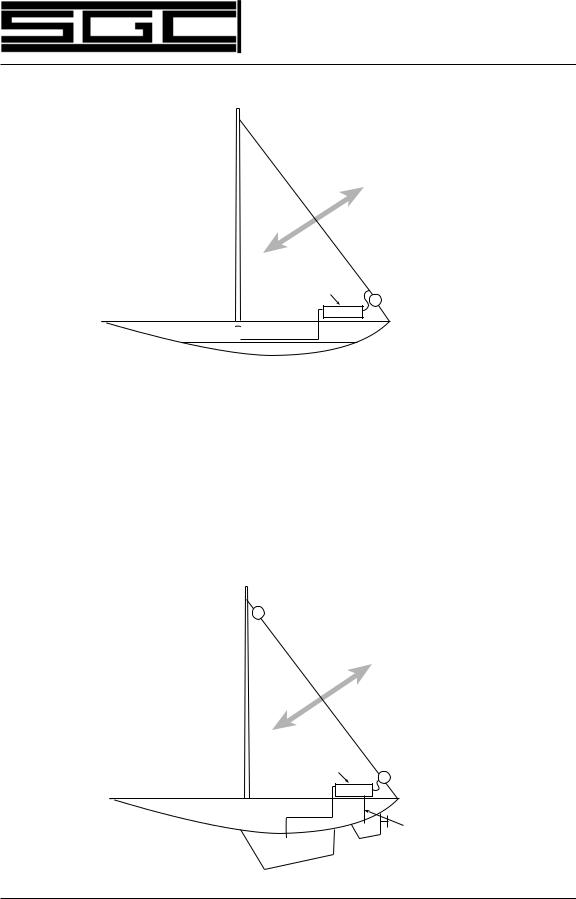
The triangular loop antenna for sailboats is designed to operate in a groundless environment and still provide high performance. This type of installation will require only one insulator point on the bottom backstay and an electrical connection on top of the mast and stay. The grounded side of the coupler is connected to the bottom of the mast. Although not our best recommendation, this antenna will provide a workable solution in some installations.
Figure 5.11 Vessel insulated backstay
Porcelain isolator
|
Radiation |
|
75 feet |
Vessel |
Coupler |
insulated |
|
Backstay |
Porcelain |
isolator |
|
|
Ground |
|
connection |
SGC Inc. SGC Building, 13737 S.E. 26th St. Bellevue, WA 98005 USA |
27 |
|
P.O. Box 3526, 98009 Fax: 425-746-6384 Tel: 425- 746-6310 or 1-800-259 7331 |
||
|
||
|
||
E-mail: sgc@sgcworld.com Web site: http://www.sgcworld.com |
© 1998 SGC Inc |
 Loading...