


SG-2000 MANUAL
SG-2000
1.6-30 MHz
150 Watt Output
Multi-Mission
HF SSB
Transceiver
Operations and Programming Manual
Revised: Oct, 1995
CAUTION: Carefully read the "Quick Start" (yellow card packed with your radio) and the "Operating the SG-2000" section of this manual beginning on Page 41. The SG-2000 is a high precision electronic device. Taking the time to learn all of its capabilities will insure maximum performance, reliability and enjoyment of the unit.
|
The SGC Building, 13737 S.E. 26th St. Bellevue, WA. 98005 USA |
|
©1995, SGC, Inc. |
TEL: (206) 746-6310 |
FAX: (206) 746-6384 |

|
|
|
SG-2000 MANUAL |
i |
|
|
|
TABLE OF CONTENTS |
|
|
|
1.0 |
General Description and Specifications....................................................... |
1 |
|||
|
|
1.1 |
General Description of the SG-2000 ........................................ |
1 |
|
|
|
1.2 |
Power Requirements ................................................................. |
|
2 |
|
|
1.3 |
SG-2000 Performance Specifications ....................................... |
2 |
|
|
|
1.4 |
Data Comunications .................................................................. |
|
3 |
|
|
1.5 |
Computer Control of SG-2000.................................................. |
3 |
|
|
|
1.6 |
Multiple Control Head Specifications..................................... |
4 |
|
|
|
1.7 |
Dimensions and Weight............................................................ |
|
4 |
|
|
1.8 |
Standard Features ...................................................................... |
|
4 |
|
|
1.9 |
External Accessories .................................................................. |
|
5 |
|
|
1.10 |
Internal Accessories ................................................................... |
|
5 |
2.0 |
Unpacking |
....................................................................................................... |
|
7 |
|
3.0 |
History of the SG-2000 ..................................................................................... |
|
8 |
||
4.0 |
About the SG-2000 ............................................................................................ |
|
10 |
||
|
|
4.1 |
Receiver Signal Path .................................................................. |
|
10 |
|
|
4.2 |
Transmitter Signal Path............................................................. |
|
11 |
|
|
4.3 |
Control Circuits .......................................................................... |
|
12 |
|
|
4.4 |
Control Heads............................................................................. |
|
13 |
|
|
4.5 |
SG-2000 Front Panel................................................................... |
|
13 |
|
|
4.6 |
SG-2000 Rear Panel .................................................................... |
|
13 |
5.0 |
SGC Family of Control Heads........................................................................ |
|
14 |
||
|
|
5.1 |
Remote Mobile Heads ............................................................... |
|
14 |
|
|
5.2 |
PowerTalk™ and PowerTalk™ SA ......................................... |
14 |
|
6.0 |
SG-2000 Software and Accessories ................................................................ |
|
15 |
||
|
|
6.1 |
GPS Software .............................................................................. |
|
15 |
|
|
6.2 |
Oil Platform Software................................................................ |
|
15 |
7.0 |
Planning for Installation ................................................................................. |
|
16 |
||
|
|
7.1 |
Location of Power Supplies ...................................................... |
16 |
|
|
|
7.2 |
Control Head Placement ........................................................... |
16 |
|
|
|
7.3 |
Control Head Wiring................................................................. |
|
17 |
|
|
7.4 |
External Speakers....................................................................... |
|
17 |
|
|
7.5 |
External Accessories .................................................................. |
|
18 |
8.0 |
Radio Licenses ................................................................................................... |
|
19 |
||
|
|
8.1 |
Station Licenses .......................................................................... |
|
19 |
|
|
8.2 |
Operator Licenses ...................................................................... |
|
20 |
|
|
|
|
|
|
|
|
|
The SGC Building, 13737 S.E. 26th St. Bellevue, WA. 98005 USA |
|
|
©1995, SGC, Inc. |
|
TEL: (206) 746-6310 |
FAX: (206) 746-6384 |
|
|

SG-2000 MANUAL
ii
|
The SGC Building, 13737 S.E. 26th St. Bellevue, WA. 98005 USA |
|
©1995, SGC, Inc. |
TEL: (206) 746-6310 |
FAX: (206) 746-6384 |

|
|
|
SG-2000 MANUAL |
iii |
|
9.0 |
Installation |
....................................................................................................... |
|
21 |
|
|
|
9.1 |
SG-2000 Rear Panel Connections ............................................. |
21 |
|
|
|
9.2 |
External Coupler Installation ................................................... |
22 |
|
|
|
9.2 |
External Modem, Weatherfax and High Seas Direct™ ........ |
23 |
|
|
|
9.3 |
Continuous Duty Ratings ......................................................... |
23 |
|
|
|
9.4 |
Rack Mount Kit Installation (Part No. 52-90)......................... |
24 |
|
|
|
9.5 |
Control Head Installations........................................................ |
27 |
|
|
|
9.6 |
Remote Head Kit Installation (Part No. 04-12) ...................... |
27 |
|
|
|
9.7 |
Additional Control Heads (Part No. 04-11) ........................... |
28 |
|
|
|
9.8 |
Remote Head Cable Extension................................................. |
29 |
|
10.0 |
Power Supplies.................................................................................................. |
|
30 |
||
|
|
10.1 |
Cabling......................................................................................... |
|
30 |
|
|
10.2 |
AC Power Supplies.................................................................... |
|
31 |
|
|
10.3 |
Transformer-Rectifier Supplies................................................ |
31 |
|
|
|
10.4 |
Mobile Power Supplies ............................................................. |
|
32 |
|
|
10.5 |
Solar-Powered Chargers ........................................................... |
33 |
|
11.0 |
Antenna Systems............................................................................................... |
|
34 |
||
|
|
11.1 |
Antenna Wire Size ..................................................................... |
|
35 |
|
|
11.2 |
Near Vertical Incidence Skywave............................................ |
36 |
|
|
|
11.3 |
Base Station and Fixed Antennas ............................................ |
36 |
|
|
|
11.4 |
Antenna Feed Lines ................................................................... |
|
37 |
|
|
11.5 |
Antenna Couplers ...................................................................... |
|
37 |
|
|
11.6 |
Mobile Antennas ........................................................................ |
|
38 |
|
|
11.7 |
QMS Recommended for Mobile Use....................................... |
39 |
|
|
|
11.8 |
Unconventional Mobile Antennas........................................... |
40 |
|
12.0 |
Operating the SG-2000 ..................................................................................... |
|
41 |
||
|
|
12.1 |
Syntax .......................................................................................... |
|
41 |
|
|
12.2 |
Front Panel .................................................................................. |
|
43 |
|
|
12.3 |
Push-Button Functions .............................................................. |
|
44 |
|
|
12.4 |
Sample Entries ............................................................................ |
|
48 |
|
13.0 Tour of the SG-2000 .......................................................................................... |
|
49 |
||
|
|
13.1 |
Front Panel Display ................................................................... |
|
49 |
|
|
13.2 |
Front Panel Controls.................................................................. |
|
52 |
|
|
13.3 |
Primary Keyboard Functions ................................................... |
52 |
|
|
|
13.4 |
Shift Functions............................................................................ |
|
57 |
|
|
13.5 |
Program Functions..................................................................... |
|
59 |
|
|
13.6 |
Operating Session ...................................................................... |
|
59 |
|
|
13.7 |
Channel........................................................................................ |
|
60 |
|
|
13.8 |
Frequency.................................................................................... |
|
61 |
|
|
|
|
|
|
|
|
|
The SGC Building, 13737 S.E. 26th St. Bellevue, WA. 98005 USA |
|
|
©1995, SGC, Inc. |
|
TEL: (206) 746-6310 |
FAX: (206) 746-6384 |
|
|

SG-2000 MANUAL
iv
|
13.9 |
Programming.............................................................................. |
63 |
|
13.10 |
Scanning Functions.................................................................... |
64 |
|
13.11 |
Changing Frequency or Channel Scan Rates ......................... |
68 |
|
13.12 |
Additional Functions................................................................. |
69 |
14.0 |
Mobile Installation ........................................................................................... |
75 |
|
|
14.1 |
Shock and Vibration Mounting................................................ |
75 |
|
14.2 |
Mobile Grounds ......................................................................... |
76 |
|
14.3 |
Vehicular Noise Sources ........................................................... |
78 |
15.0 |
Marine Installation ........................................................................................... |
80 |
|
|
15.1 |
Marine Radio Mounting ........................................................... |
80 |
|
15.2 |
Marine Ground Systems ........................................................... |
80 |
|
15.3 |
Marine Antennas........................................................................ |
82 |
|
15.4 |
High Seas Direct™ Connections .............................................. |
82 |
16.0 |
Remote Control.................................................................................................. |
85 |
|
|
16.1 |
Extension of Control Head Wiring.......................................... |
85 |
|
16.2 |
Short Haul Modems/Auto-Answer Devices ......................... |
86 |
|
16.3 |
Line of Demarcation .................................................................. |
86 |
|
16.4 |
Auto-Answer Devices ............................................................... |
87 |
|
16.5 |
Computer Networks - Serial Control...................................... |
87 |
17.0 |
External Software .............................................................................................. |
88 |
|
|
17.1 |
RS-232 Serial Control Software ................................................ |
88 |
|
17.2 |
RS-232 Software Installation..................................................... |
89 |
|
17.3 |
Main Menu Display ................................................................... |
92 |
|
17.4 |
Main Menu Operations ............................................................. |
93 |
|
17.5 |
Menu 2 Operations .................................................................... |
95 |
|
17.6 |
Programming Functions ........................................................... |
96 |
|
17.7 |
PC Cable Assembly.................................................................... |
98 |
18.0 ALE and Adaptive Controllers ....................................................................... |
100 |
||
|
18.1 |
SG-2000 Serial Port Operation.................................................. |
101 |
|
18.2 |
Serial Communication Protocol ............................................... |
102 |
|
18.3 |
ALE Controller-Command Examples..................................... |
103 |
|
18.4 |
Recall a Selected SG-2000 Memory Into Active Use ............. |
103 |
|
18.5 |
SG-2000 Connections to ALE Controller ................................ |
104 |
19.0Accessories 106
19.1 |
Exsel-100 Selective Calling System.......................................... |
106 |
|
19.2 |
Telerex™ ARQ/FEC/SELFEC System ................................... |
107 |
|
|
The SGC Building, 13737 S.E. 26th St. Bellevue, WA. 98005 USA |
|
|
©1995, SGC, Inc. |
TEL: (206) 746-6310 |
FAX: (206) 746-6384 |
|

SG-2000 MANUAL |
v |
20.0 Answers to Frequently Asked Questions..................................................... |
108 |
|
The SGC Building, 13737 S.E. 26th St. Bellevue, WA. 98005 USA |
|
©1995, SGC, Inc. |
TEL: (206) 746-6310 |
FAX: (206) 746-6384 |

|
|
SG-2000 MANUAL |
vi |
21.0 |
Technical Reference.......................................................................................... |
110 |
|
|
21.1 |
Squelch Scale Recalibration ...................................................... |
110 |
|
21.2 |
SG-2000 Microprocessor Reset Procedure.............................. |
110 |
|
21.3 |
Emergency Calling..................................................................... |
111 |
|
21.4 |
Basic Tune-up Procedure (Alignment) ................................... |
112 |
|
21.5 |
AM Filter Bypass........................................................................ |
113 |
|
21.6 |
Oscillator and Filter Operation ................................................ |
113 |
|
21.7 |
Microprocessor Assembly ........................................................ |
115 |
|
21.8 |
VCO's ........................................................................................... |
115 |
|
21.9 |
PLL's............................................................................................. |
115 |
|
21.10 |
Serial Logic Switches ................................................................. |
116 |
|
21.11 |
Tone Generator........................................................................... |
116 |
|
21.12 |
Oven Switch................................................................................ |
116 |
|
21.13 |
Alarm Generator ........................................................................ |
116 |
|
21.14 |
Master Oscillator with Oven .................................................... |
117 |
|
21.15 |
Crystal Oven ............................................................................... |
117 |
|
21.16 |
Output Low Pass Filters............................................................ |
118 |
|
21.17 |
Automatic Level Control .......................................................... |
118 |
|
21.18 |
Modulation Characteristics, AFR ............................................ |
118 |
|
21.19 |
Modulation Characteristics, PEP Limiting............................. |
119 |
|
21.20 |
SG-2000 Performance Measurements ..................................... |
121 |
22.0 |
Trouble Shooting .............................................................................................. |
127 |
|
|
22.1 |
Dysfunctions ............................................................................... |
127 |
|
22.2 |
Scanning in One Direction Only .............................................. |
128 |
23.0 |
Test Procedures.................................................................................................. |
129 |
|
|
23.1 |
Exciter Testing Procedures ....................................................... |
129 |
|
23.2 |
LPA Testing Procedures............................................................ |
156 |
|
23.3 |
Display Section Testing Procedures ........................................ |
163 |
|
23.4 |
Head CPU and Main CPU Testing Procedures ..................... |
171 |
|
23.5 |
Final Assembly Testing Procedures ........................................ |
178 |
24.0 |
Schematic Reference Section .......................................................................... |
180 |
|
INDEX ....................................................................................................................... |
|
210 |
|
Appendix A, Frequency List ....................................................................................... |
A-1 |
||
|
The SGC Building, 13737 S.E. 26th St. Bellevue, WA. 98005 USA |
|
©1995, SGC, Inc. |
TEL: (206) 746-6310 |
FAX: (206) 746-6384 |

SG-2000 MANUAL |
1 |
1.0General Description and Specifications
This section includes a short description of the features of the SG-2000 Transceiver along with its specifications. This manual includes information useful for the SG-2000, the SG-2000 SlimPak, and the Military version (PRC-2250 MIL).
1.1General Description of SG-2000
Model |
SG-2000 |
Channels |
100 channels field programmable |
|
644 factory programmed ITU voice and data channels |
Scan channels |
Up to 100 channels programmable in 6 groups of 10 |
|
channels each |
Scan frequency |
In 0.1, 0.5, 1, 3, and 5 KHz steps |
Scan frequency |
|
range |
Full HF range or a selected range of frequencies |
Scan dwell time |
Adjustable from .1 to 40 seconds |
|
Frequency scan dwell: .1 to 1 second |
Transmitter |
Channel dwell time: .2 to 40 seconds |
|
|
frequency range |
1.6 to 30 MHz |
Receiver frequency |
|
range |
1600 KHz to 30 MHz (500 KHz - 30 MHz Optional) |
Frequency stability |
±10 Hz |
Frequency resolution |
100 Hz |
Modes |
A3A, A3H, A3J and CW in LSB and USB, True AM detector in |
|
receive mode. Data modes supported by external controllers. |
Protection |
Fully protected against damage due to battery reversal, over |
|
voltage, or antenna fault (open or short). |
Display |
LCD for frequency or channel with annunciators of all |
|
functions and modes, 20-segment bar meter, and time or |
|
date |
Metering |
S-meter in RX mode, forward power or VSWR in TX mode |
AGC |
Fast attack slow release in Voice mode. Extremely fast attack |
|
fast release in telex and ALE modes. |
Keypad |
21 push-buttons include power, up/down, all functions, and |
|
numeric entry |
|
The SGC Building, 13737 S.E. 26th St. Bellevue, WA. 98005 USA |
|
©1995, SGC, Inc. |
TEL: (206) 746-6310 |
FAX: (206) 746-6384 |

|
SG-2000 MANUAL |
2 |
Alarm generator |
Programmed for standard ITU and CCIR alarm on |
|
|
emergency frequency 2182 KHz or can be broadcast on any |
|
|
frequency. Having to press two push-buttons simul- |
|
|
taneously to activate transmitter prevents accidental alarm. |
|
Operating |
|
|
temperature |
-45° to 85° C |
|
Full specification |
|
|
temperature |
-30° to 60° C |
|
Approvals |
FCC type accepted, parts 80, 87 and 90. DOC |
and |
|
CEPT(pending). Meets CCIR specification for receiver and |
|
|
transmitter* (see page 5) |
|
Color |
Black |
|
Front panel |
Splash proof, removable and may be mounted remotely |
|
1.2Transceiver Power Requirements
Nominal |
13.6 VDC; 0.8A RX, 16A TX (voice) |
Full specification |
|
compliance |
11.5 VDC |
Full operation |
10.5 to 18.0 VDC |
Current drain when |
|
radio off: |
|
STBY mode, |
|
Oven on; |
430 mA |
oven off; |
80 mA |
1.3SG-2000 Performance Specifications
|
RECEIVER SPECIFICATIONS |
|
|
|
Sensitivity |
.5µV produces .5W of audio with 10dB SNR (Signal to |
|
|
|
noise ratio may vary from 7 to 16 dB at nominal .5 µV |
|
|
|
input) |
|
|
Selectivity |
2.4 KHz at -6 dB; 4 KHz at -60 dB shape factor better |
|
|
|
than 2:1) |
|
|
Intermodulation |
+86 dB (CCIR specification) |
|
|
Blocking |
+100 dB (CCIR specification) |
|
|
Transmodulation |
+ 95 dB (CCIR specification) |
|
|
Image and IF |
|
|
|
rejection |
+90 dB |
|
|
Audio output |
4W with less than 10% distortion |
|
|
Audio distortion |
Less than 5% at 3W |
|
|
|
|
|
|
|
The SGC Building, 13737 S.E. 26th St. Bellevue, WA. 98005 USA |
|
©1995, SGC, Inc. |
TEL: (206) 746-6310 |
FAX: (206) 746-6384 |
|

|
SG-2000 MANUAL |
3 |
AGC response |
Less than 5dB variation at the output for 5µVolt to 1 |
|
|
Volt RMS at the receiver input |
|
Clarifier range |
±600 Hz in 100 Hz steps |
|
Receiver protection |
Up to 50 Volt RMS at the receiver input |
|
Squelch |
Voice operated with syllabic detection — adjustable |
|
|
threshold |
|
Speaker |
Internal ( on removable front panel) |
|
TRANSMITTER SPECIFICATIONS |
|
|
Power output in |
|
|
50 ohms |
150 watts* PEP ( +0dB to -.5 dB) (see page 5) |
|
Power output |
|
|
reduction |
To less than 50 watts PEP |
|
Maximum stress |
|
|
power output |
225 watts CW*** (see page 5) |
|
Sideband suppression |
Better than -50 dB at 1400 Hz |
|
Harmonic |
|
|
suppression |
Better than -63 dB** (see page 5) |
|
Carrier suppression |
(A3J) Better than -55 dB |
|
Carrier level |
(A3H) -3 dB |
|
|
(A3A) -16 dB |
|
Noise suppression |
Better than -60 dB |
|
Distortion |
|
|
(third order) |
Better than -32 dB at 135W PEP |
|
Audio response |
Flat within 6 dB between 350 & 2400 Hz |
|
VSWR protection |
For 4:1 VSWR, power output will reduce below 50 |
|
|
watts PEP |
|
Thermal protection |
For 80°C power output will reduce below 50 watts PEP |
|
1.4Data Communications
Ready and compatible |
RTTY, ARQ, FEC, PACKET and telegraphy |
Receive/transmit |
|
switching time |
10 mS nominal |
AFSK input/output |
|
impedance |
600? |
AFSK input level |
Minimum required 100 mV RMS, 2V RMS maximum |
AFSK output level |
240mV RMS at .5µV, maximum 1V RMS |
1.5Computer Control of SG-2000
|
Input/Output |
RS 232 |
|
|
|
|
|
|
|
The SGC Building, 13737 S.E. 26th St. Bellevue, WA. 98005 USA |
|
©1995, SGC, Inc. |
TEL: (206) 746-6310 |
FAX: (206) 746-6384 |
|
|
SG-2000 MANUAL |
4 |
Access and recall |
Of all transceiver functions except audio |
|
Software |
SG-2000 for DOS (Supplied with |
C language source |
|
code) |
|
System software |
DOS Ver. 3.0 or greater for IBM and compatibles (user |
|
|
supplied) |
|
|
The SGC Building, 13737 S.E. 26th St. Bellevue, WA. 98005 USA |
|
©1995, SGC, Inc. |
TEL: (206) 746-6310 |
FAX: (206) 746-6384 |

SG-2000 MANUAL |
5 |
1.6Multiple Control Head Specifications
Local |
One controller mounted to the radio (except SlimPak) |
Remote |
Up to 50 meters away from the radio (10 wires) |
Intercom |
On all remotes |
Maximum number of |
|
controllers |
8 (Total of control heads and computers not to exceed 8) |
Telephone remote |
Through standard telephone line and modem with |
|
telecommunication software and SGC-RS-232 software |
1.7Dimensions and Weight
Overall Dimensions |
11.7 (H) x 25.4 (W) x 38 (L) cm 4.75 in. (H) x 10 (W) x 15 |
|
(L) inches (SlimPak 1" less in height) |
Weight |
5.4 kg (12 lbs) |
1.8Standard Features
•Full remote control, up to 8 stations
•Upper or lower sideband select
•A3A, A3H and A3J select
•Emergency 2182 direct select (Standard Head only)
•Voice or Telerex (narrow band) filter select
•CW side tone oscillator, CW with break-in
•Alarm Generator
•Speaker on/off, rear panel audio I/O port for modems, Weatherfax
•Headset/handset driver separate from speaker
•Carbon or dynamic microphone select switch
•Squelch on/off and level set
•Coupler tuned indicator
•20 dB receive attenuator
•Transmitter power level set (50 or 150W)
•Transmitter over temperature indication and thermal protection
•Receive S-meter and transmit forward power or SWR meter display
•Time of day or date display
•Radio on/off timer
•Intercom with all stations or private channel select
|
The SGC Building, 13737 S.E. 26th St. Bellevue, WA. 98005 USA |
|
©1995, SGC, Inc. |
TEL: (206) 746-6310 |
FAX: (206) 746-6384 |

SG-2000 MANUAL |
6 |
1.9External Accessories
•Marine antennas
•Vehicular antennas
•Whip antenna in 8, 23, 28 or 35 ft. lengths
•SG-103 broadband antenna, 2-28 MHz
•SG-103-T tactical broadband antenna, 2-28 MHz
•Dipole antenna for 1,2 & 3 specified frequencies
•Field adjustable dipole antenna
•SGC Portamast
•SG-230 150 Watt MicroProcessor controlled antenna coupler
•SG-230 Pro 150 Watt MicroProcessor controlled antenna coupler
•SG-235 500 Watt MicroProcessor controlled antenna coupler
•PS-30 power supply for base station (unregulated)
•PS-35 power supply for base station (regulated)
•Standard mounting tray
•Shock mounting tray for high vibration installations
•Battery cable
•External speaker
•CW telegraphy key
•Dynamic desk and noise canceling fist microphone
•Military handset (waterproof, dustproof, shock-proof)
•Telephone handset
•Tel-Two phone patch
•Linear power amplifiers, 500 & 1000 watts output
•Front panel customizing
•TELEREX ARQ, FEC and PACKET systems
•ALE adaptive controller
1.10Internal Accessories
•High power CW continuous fan kit
•ALE (Automatic Link Establishment) AGC switching (Specify at time
of order)
• Special Software options: Hong Kong, France (and Territories), Oil Platform
|
Notes: * |
CFT8DK SG-2000 (1.8 to 26 MHz international radio marine bands) |
|
** |
For international marine bands |
|
|
|
|
|
|
|
|
The SGC Building, 13737 S.E. 26th St. Bellevue, WA. 98005 USA |
|
©1995, SGC, Inc. |
TEL: (206) 746-6310 |
FAX: (206) 746-6384 |
|

SG-2000 MANUAL |
7 |
***Under ambient temperature and normal load conditions
|
The SGC Building, 13737 S.E. 26th St. Bellevue, WA. 98005 USA |
|
©1995, SGC, Inc. |
TEL: (206) 746-6310 |
FAX: (206) 746-6384 |

SG-2000 MANUAL |
8 |
DO NOT ATTEMPT TO TRANSMIT UNTIL THE RADIOTELEPHONE IS WARMED UP FOR AT LEAST TEN MINUTES.
The crystals that control the operating frequency are contained in a precision oven that requires 10 minutes to rise to the correct temperature. Transmitting before the 10 minute warm-up period has elapsed may cause a violation of FCC regulations.
Precautions:
1.Operating and installation personnel must observe all applicable safety regulations at all times. Do not operate unit without covers in place with power on. Under certain conditions, dangerous electrical voltages may exist. To avoid injuries, always confirm removal of power and discharge and ground all circuits before touching them.
2.Do not service or adjust equipment when alone. Under no circumstances should you reach into live equipment for the purposes of adjustment or servicing unless there is someone else present who is capable of rendering aid.
3.Personnel working with or near AC power sources, power supplies and high power radio equipment should be familiar with modern first aid techniques and resuscitation.
4.When servicing, observe static discharge precautions to avoid damage to microprocessors and solid state devices.
5.When servicing multiple control head installations, disconnect all remote heads at J-503 on the rear panel of SG-2000 to prevent other personnel from keying the transmitter during servicing.
SGC reserves the right to change specifications without notice.
2.0Unpacking
The standard packaging for an SG-2000, the cardboard box and packing materials, should be retained for future use should the radio need to be shipped elsewhere.
|
The SGC Building, 13737 S.E. 26th St. Bellevue, WA. 98005 USA |
|
©1995, SGC, Inc. |
TEL: (206) 746-6310 |
FAX: (206) 746-6384 |

SG-2000 MANUAL |
9 |
Please note that the radio arrived in a polyethylene bag which includes the instruction manual, warranty registration card and a quick reference card. Information on use of AT&T High Seas services is also provided for your convenience. The plastic bag protects the unit from dust and moisture when shipping. If there is condensation on the inside of the polyethylene bag because the radio was subjected to extreme change of temperature during shipment, please leave the plastic covering on the radio until it has come up to ambient temperature and the condensation has evaporated.
You will notice a piece of foam rubber on the face plate of the radio, held in place with tape. It is designed to protect the plastic face plate of the LCD. Whenever you are shipping an SG-2000, it is good practice to secure a cover over the LCD. Small scratches in the face plate of the LCD may be removed with Plexiglas™ cleaner such as is used to clean aircraft windows.
The SG-2000 should be closely inspected upon arrival. As the units leave the SGC factory, they are in perfect operating condition. Should you notice any bent sheet metal, or flecks of paint in the shipping box, you may assume that the radio has taken a hard shock somewhere in shipping.
The radio will usually continue to operate, even if subjected to abuse in shipping, but please make sure that if you notice any shipping damage, you file a damage report immediately with the carrier.
In the unlikely event that your unit has been damaged in shipping, your dealer can instruct you on how to handle servicing or replacing the unit. If your dealer does not know the proper procedure, you may contact SGC directly.
SGC provides a complete five-year parts and labor guarantee. However, this guarantee does not apply to radios which are used in para-military and military operations, as combat conditions are specifically excluded from our guarantee.
|
The SGC Building, 13737 S.E. 26th St. Bellevue, WA. 98005 USA |
|
©1995, SGC, Inc. |
TEL: (206) 746-6310 |
FAX: (206) 746-6384 |

SG-2000 MANUAL |
10 |
3.0History of the SG-2000
The SG-2000 is a high performance, microprocessor (computer) controlled multimission HF SSB radio designed to meet the needs of marine, commercial, para-military, and amateur radio users through the year 2000 and beyond.
The SG-2000's heritage includes the SG-705, the world's smallest commercial HF SSB, the SG-715 waterproof manpack radio, and the SG-712 EX-11 which has been proven in commercial and military applications in all regions of the world.
The SG-2000 also benefits from SGC's expertise in microprocessor design, developed as the company evolved its line of fully automatic antenna couplers. SGC's fully automatic antenna couplers have been available since 1975 and the current computerized SG-230 series of couplers has been continuously upgraded to maintain technical dominance through software enhancements.
The SG-2000 was conceived by SGC President Pierre Goral and the SGC Engineering staff to meet an emerging need in HF communications for a relatively low cost, highly reliable yet flexible communications platform which would be suited to multiple controlpoint operation and would allow complete computer control if desired.
This was done after a careful study of emerging HF radio technology in the military and government sector and with an eye to providing the users of SGC equipment with the highest level of flexibility, not only today but in the future as well.
It was clear from the SGC analysis that to an increasing degree, personal computers would be integrated into mobile, fixed, and sea going radio operations. In addition, a whole new field called Adaptive Controllers was being developed for government and military use.
The SG-2000 design project became an all-consuming effort among the team members who studied all available information in order to provide a radio which would meet modern communications needs. The process was to collect and analyze all available trend information, review not only cutting edge but projected technology, and then build the radio that would meet all of these needs.
It is interesting to note the design team's criteria:
•The ideal radio would weigh as little as possible, under 6 kilograms would be ideal. The radio would need to operate from any location. This meant telephone
line control for control at distances of several thousand miles, or by hard wire
|
The SGC Building, 13737 S.E. 26th St. Bellevue, WA. 98005 USA |
|
©1995, SGC, Inc. |
TEL: (206) 746-6310 |
FAX: (206) 746-6384 |

SG-2000 MANUAL |
11 |
control for local use at short to moderate distances.
•This radio would need to be controllable by a computer or its own control heads and it would have to support control from up to eight locations all at the same time. It would also be nice if the radio could be directed through a local area network with one computer on the network operating as a gateway.
•In addition, the eight locations would have to be connected via an intercom, the radio would need to be of high physical strength, and would be able to operate over extremes of temperature and humidity.
The SG-2000 would also have to meet exacting performance standards for frequency stability and for speed of operations in order to accommodate some of the more exotic demands of the para-military and military markets.
The result of the design effort is the SG-2000, the world's first truly computer-directed civilian radio. Many of the attributes of the SG-2000 can be found in very expensive military units, some costing 10 times the price of an SG-2000 and not generally available to the public.
In 1992, SGC introduced a ruggedized version of the SG-2000 designed for para-military use called the PRC-2250 MIL. This radio features many SG-2000 options ordered by (para) military organizations. It is finished in an olive drab color and comes with a military type shock mount with a waterproof handset standard, which distinguishes it from the SG-2000 in appearance.
In 1994, SGC introduced a SlimPak version. The SlimPak has all the features of the SG2000 and uses the same control head; yet the main unit measures a full 1 inch less in height, enabling placement in much tighter quarters.
In 1995, SGC introduced a new model of the SG-2000 control head called the PowerTalk™ that incorporates ADSP™ and SNS™ noise reduction and noise filtering capabilities.
|
The SGC Building, 13737 S.E. 26th St. Bellevue, WA. 98005 USA |
|
©1995, SGC, Inc. |
TEL: (206) 746-6310 |
FAX: (206) 746-6384 |
SG-2000 MANUAL |
12 |
4.0About the SG-2000
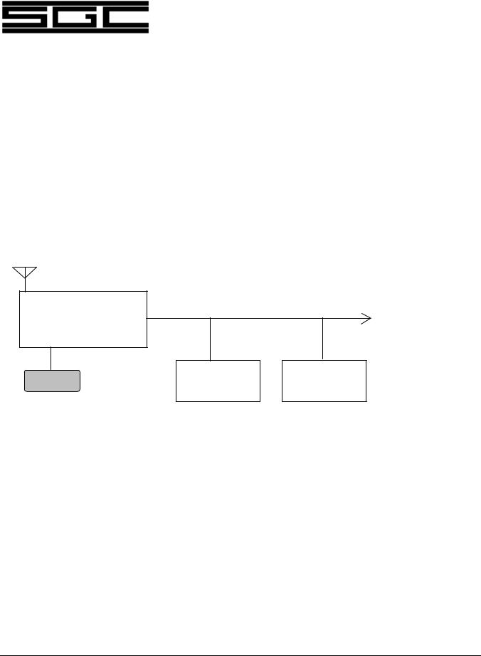
The basic SG-2000 is really two units, which may be easily separated. One unit is what is called the Radio or RF unit. This contains the receiver and the transmitter's exciter and linear power amplifier modules. In addition, it contains the SG-2000's main microprocessor.
The second unit, normally supplied attached to the radio unit, is called the control head. In it are audio amplifiers, the radio's frequency and channel displays, a keyboard to control radio functions and another microprocessor which "talks" to the main radio unit.
Audio wiring at 600 ohms plus |
|
RS-422 (9600 baud) Serial Bus |
|
SG-2000 RF Unit |
|
|
To additional heads |
|
(8 maximum) |
Control Head |
Control Head |
RS-232 (9600 baud) Serial Port for computer
One control head may be attached to the SG-2000 RF unit. Up to seven others may be located up to 50 meters
away from the RF unit using 10-conductor cable.
4.1Receiver Signal Path
The receiver section, located in the main radio unit, features signal up conversion (from 82 to 88 MHz) to achieve maximum image rejection and to allow wide band processing of signals. Then the signal is converted down to 10.7 MHz where an extraordinarily sharp crystal filter removes all unwanted signals, including strong unwanted signals which have not been eliminated by the 82-88 MHz filters.
The 10.7 MHz signal is further amplified and is then decoded by one of the two detectors in the radio. For single sideband, CW (Morse Code), and data operations, a product detector is used. For AM, the SG-2000 provides one of the few "true AM" detectors available today. This provides for extremely clear reception and excellent
|
The SGC Building, 13737 S.E. 26th St. Bellevue, WA. 98005 USA |
|
©1995, SGC, Inc. |
TEL: (206) 746-6310 |
FAX: (206) 746-6384 |

SG-2000 MANUAL |
13 |
capture of signals in all modes.
|
The SGC Building, 13737 S.E. 26th St. Bellevue, WA. 98005 USA |
|
©1995, SGC, Inc. |
TEL: (206) 746-6310 |
FAX: (206) 746-6384 |
SG-2000 MANUAL |
14 |
Once amplified to a standard level, the audio is which allows for connection to a control head. further amplified and processed.
sent to a jack on the back of the SG-2000 In the control heads, the audio signal is
A syllabic squelch circuit (which was pioneered by SGC in 1976) is used to turn off the noise coming out of the speaker in the event that a signal is not being received.
The next step is a digital gate which controls the volume of the receiver by very rapidly sampling the signal and passing only a certain number of samples — a number which varies by the setting of the volume control on the front panel of the radio. Naturally, this happens at speeds which you can not hear, so your ear hears smooth control of the volume function.
4.2Transmitter Signal Path
Pressing the push to talk button grounds the push-to-talk line, placing the SG-2000 in the transmit mode. At the same time, the sound of your voice is shaped by an audio amplifier in the control head. This is brought up to a standard level to be sent out the transmit audio bus.
This line leaves the control head via the 10-conductor control head cable and returns to the SG-2000 RF unit via the rear panel connector where the head plugs into the rear panel of the radio.
Inside the radio, the audio signal is shaped and amplified. It is turned into an AM signal which is then processed to remove the desired amount of carrier. This is accomplished by a balanced modulator. In the single sideband mode, all of the carrier is removed. If required, the carrier is reinserted for other modes.
In the AME (AM Equivalent) mode, 40-50 W of the carrier is reinserted. And if you are operating in the A3A mode which is used for certain kinds of commercial radio work, then you put back about 1/8th of the carrier, leaving just enough of the signal to act as a "pilot carrier" for specialized receivers.
Next, the signal is amplified and passed through a crystal filter, where one sideband is removed. This is done by offsetting the transmit frequency slightly. On one side of the filter slope, the upper sideband is removed, while offsetting on the other side of the 10.7 MHz filter will remove the lower sideband.
When you are in the single sideband mode, you have now developed either the desired upper or lower sideband filter at this point. From here on, the amplifiers which will be processing the signal are called "linear amplifiers" because if they are not linear, they will distort the signal, just like a non-linear audio amplifier would distort a signal on your home stereo.
The 10.7 MHz single sideband signal is then converted up to 82-88 MHz, where harmonics are eliminated by the helical filter. The output of the 82-88 MHz filter is
|
The SGC Building, 13737 S.E. 26th St. Bellevue, WA. 98005 USA |
|
©1995, SGC, Inc. |
TEL: (206) 746-6310 |
FAX: (206) 746-6384 |

SG-2000 MANUAL |
15 |
mixed with the correct frequency developed by the synthesizer and is then amplified at the operating frequency.
This amplification process involves several steps: a pre-driver, a driver, and a final amplifier section which utilizes a splitter - combiner circuit
The pre-driver and the driver sections are very straight-forward in design. But the final LPA (Linear Power Amplifier) deserves special note because it is very conservatively constructed. This amplifier is made up of four transistors. While most designers will use only two, SGC elected to use four for reliability and peak power performance.
Controlling the LPA is a circuit called ALC (Automatic Level Control) which adjusts the operating conditions of the final amplifier to insure its operation is linear over a wide range of conditions.
A broad band filter network then matches the high power signal to a 50 ohm output impedance. This is then sent to the SG-230 Smartuner (which we highly recommend) or a broad band antenna system such as the SG-103.
4.3Control Circuits
The SG-2000 is a microprocessor controlled radio. Each of the control heads has a microprocessor and talks to the microprocessor in the radio unit using the RS-422 communications protocol. This means that the control head may be placed as much as 50 meters away from the radio. Although not supported by SGC, many users of the control heads have reported success at longer distances. As with all SGC specifications, 50 meters is a conservative number.
The microprocessor control codes, which are generated when the front panel push buttons are pushed, are sent to the microprocessor in the radio unit which return confirmation to the control head that the instructions have been acted upon. The head microprocessor controls the display information and functions such as setting of volume and squelch levels.
Each of the control heads has a unique device address which allows the microprocessors in the radio unit to send information as well as establish the intercom address of the control head.
In the event that you wish to address the microprocessors on the radio unit directly, you may use the RS-232 serial port which is located on the rear panel of the radio.
Any number of serial ports and heads may be used, as long as the total number of device addresses does not exceed eight. Four control heads and four computers works as well as one control head and seven computers.
|
The SGC Building, 13737 S.E. 26th St. Bellevue, WA. 98005 USA |
|
©1995, SGC, Inc. |
TEL: (206) 746-6310 |
FAX: (206) 746-6384 |

SG-2000 MANUAL |
16 |
For more information on controlling the SG-2000 via computer, see Section 16.5 of this manual regarding "Computer Networks - Serial Control" and the parts of Section 17.0 dealing with RS-232 software.
4.4Control Heads
There are several design considerations behind the SG-2000 control head which you should know about in order to appreciate the beauty of the architecture of the radio.
Our many years of manufacturing experience have taught us the value of absolute reliability and of the importance of easy reparability in the field. Such philosophies as designing in a 10-conductor control cable between our radios and remote heads rather than a fiber optic cable is one example. SGC has learned that while fiber optics are an excellent material, they are not easily reparable in the middle of the desert or ocean. SGC products are designed for field repair and performance where well-engineered products dramatically become evident.
4.5SG-2000 Front Panel
The front of the SG-2000 controls all radio functions. All of the push buttons are rubberized to provide good tactile response and to keep the radio highly resistant to water and dust, two of the worst enemies of electronic equipment.
The LCD which displays the frequency is the largest available on a radio of this type. The speaker is treated to resist moisture. The speaker grill is designed to prevent direct spray from hitting the speaker.
Because the front panel has been ruggedly built, the advantage of mounting the more sensitive radio unit elsewhere becomes apparent.
4.6SG-2000 Rear Panel
A series of Jacks on the back of the SG-2000 provide access to radio features and accessories. Most of these jacks are covered by a metal "U" bracket which is held in place by three small Phillips head machine screws. If you ever have occasion to remove this cover, it is important that it be replaced in order to provide physical protection for the jacks.
Under the "U" bracket, from left to right, you will find a jack to plug in one of the family of SGC's Smartuners. The next plug (J-301) presents audio input and output lines, plus push-to-talk control. This is where Weatherfax, data controllers (such as an SGC Telerex™ SITOR modem), and ALE units are plugged in.
The next two jacks are for plugging in two control heads. If you are using more than one control head, one will plug in to the right hand head plug while a multiple plug adapter unit plugs into the left control head jack and provides for up to seven additional head connections.
|
The SGC Building, 13737 S.E. 26th St. Bellevue, WA. 98005 USA |
|
©1995, SGC, Inc. |
TEL: (206) 746-6310 |
FAX: (206) 746-6384 |

SG-2000 MANUAL |
17 |
The last jack, J505, is used for connecting an external speaker. This is also the most common connection for the Weatherfax.
In addition, just to the right of the "U" bracket is an RS-232 connector for computer control of the SG-2000 radio, as explained later in this manual.
|
The SGC Building, 13737 S.E. 26th St. Bellevue, WA. 98005 USA |
|
©1995, SGC, Inc. |
TEL: (206) 746-6310 |
FAX: (206) 746-6384 |

SG-2000 MANUAL |
18 |
5.0SGC Family of Control Heads
The SG-2000 comes with the standard control head described throughout this manual. In addition, there are six other control heads to choose from. These range from the small remote mobile heads to the new PowerTalk™ head incorporating ADSP™ and SNS™ noise reduction capabilities.
5.1Remote Mobile Heads
The four models of the remote mobile heads are designed to be used in conjunction with the SG-2000. They have simplified control functions and a much smaller footprint. They include the basic version, the aircraft version, the Exsel version and the remote mobile head with ADSP™ noise reduction.
Please contact SGC for information on any of these optional heads.
5.2PowerTalk™
Another optional control head is our newly released PowerTalk™ head. The PowerTalk™ head is the same size as the standard remote head but with more versatility, including the additional benefit of state of the art noise reduction circuits to let the user filter out unwanted noise.
Please contact SGC for information on this model.
|
The SGC Building, 13737 S.E. 26th St. Bellevue, WA. 98005 USA |
|
©1995, SGC, Inc. |
TEL: (206) 746-6310 |
FAX: (206) 746-6384 |

SG-2000 MANUAL |
19 |
6.0SG-2000 Software and Accessories
This section lists various software options that are available for the MicroProcessor controlled SG-2000. In the event that you own an SG-2000 and later wish to add different software, such as the GPS software, Oil Rig software, Hong Kong software, or other software as may be periodically published, please be advised that there is a software update charge if the software is retrofitted into an existing radio.
6.1GPS Software
Effective April 1, 1992, a special edition of the SG-2000 main microprocessor software was published to meet the needs of the oil and gas exploration industry for a radio which would not search the international emergency frequency, 2182 KHz, when the radio is first turned on. The special software is now standard.
In addition, the SG-2000, which was adapted to differential GPS radio location service in January of 1992 has special cooling modifications which allow it to operate under severe service for unlimited time. The additional cooling systems may be ordered by users who anticipate extended key down operations, including differential GPS, ALE, SITOR/AMTOR/RTTY, and other data modes or plan to subject the SG-2000 to unusually warm operations (such as desert vehicle installations).
6.2Oil Platform Software
In May 1992, special software became available for the main MicroProcessor of the SG2000 which will allow the transmission of an emergency distress tone on all frequencies, removing the normal limit of transmitting on only the international emergency frequency, 2182 KHz. This was done at the request of oil exploration companies who have been using the SG-2000 successfully in offshore oil exploration work and who are required, because of international regulations, to both test and operate their emergency distress beacons on frequencies in addition to the international 2 MHz band channel. This software is now standard on the SG-2000. Press the shift function and emergency buttons at the same time and the distress tone will be transmitted on the displayed frequency.
Effective September 1, 1992, a special edition of the SG-2000 became available to users of the SG-2000 in Hong Kong. Certain radio programming features are deleted in order to meet Type Approval requirements of Hong Kong's G.P.O.
|
The SGC Building, 13737 S.E. 26th St. Bellevue, WA. 98005 USA |
|
©1995, SGC, Inc. |
TEL: (206) 746-6310 |
FAX: (206) 746-6384 |

SG-2000 MANUAL |
20 |
7.0Planning for Installation
Before installing the SG-2000, some pre-planning based on the capabilities and features of this radio should be undertaken to ensure the best possible performance.
7.1Location of Power Supplies
If you are installing your SG-2000 in a normal environment, such as a radio room of a ship or in a room of an office building or home, placement of the power supply is not critical as long as it is placed within 25 feet of the radio.
If you are installing the radio in a small boat, such as a cruising sailboat or an offshore fishing boat, you may wish to consider an additional gel cell (sealed) battery for radio operation. In this way, should the vessel take on water during a storm, the radio will continue to be operational.
A good way to install such a system is to place the "radio battery" in the vicinity of the radio and place an isolator between the radio battery and the rest of the battery system. When connected to the vessel's main batteries, the radio battery will prevent the voltage drop which may develop on long cable runs and will assure peak radio performance.
7.2Control Head Placement
One of the advantages of SG-2000 / PRC-2250-MIL ownership is that control heads may be placed anywhere within 50 meters of the radio unit. This provides a high degree of installation flexibility. Consider some of the more common civilian uses.
Marine. On a vessel, you may want to have a control head located at the bridge, navigation station, in the cockpit of the vessel and perhaps in staterooms. If you are planning extended cruising on a typical ocean-going sailboat, usually two heads are planned, one at the navigation station and another in a watertight case in the cockpit. This is because in most serious ocean cruising, the owner's stateroom is not used as often as the navigator's quarter berth, usually located very close to the navigation station.
Mobile. Installation in a mobile environment is something else. If you are the only radio operator on a small four wheel drive vehicle, such as a Chevrolet Geo Tracker, which we use as a test bed for mobile systems, you will likely have a single control head and this would be mounted on the dashboard using the 5-way suction cup mount.
If your mobile installation is larger, as in a bus or large recreational vehicle, you may wish to have one control head in the rear area and another control head in the vehicle
|
The SGC Building, 13737 S.E. 26th St. Bellevue, WA. 98005 USA |
|
©1995, SGC, Inc. |
TEL: (206) 746-6310 |
FAX: (206) 746-6384 |

SG-2000 MANUAL |
21 |
cockpit.
Aviation. Installation on aircraft presents an unusual challenge. In most cases, the control head is mounted separately from the radio. This allows the radio unit to be placed very close to the aircraft center of gravity.
7.3Control Head Wiring
The control head cables which are used with the SG-2000 are designed for use in normal conditions. This means that the cables are suitable for use in mobile and fixed installations. Very high vibration environments and mounting in military situations require special precautions.
In high vibration environments, wire chaffing must be avoided. Although it will take more installation time, secure all wiring tightly to prevent movement. Once movement begins, the protective covering of wiring can be quickly worn away. This is especially true on a tug boat, for example, where vibration caused by the ship's large propeller can cause 1/8" to 1/2" vibration and rates of 10 cycles per second or more. A shaking control head wire moving even a fraction of an inch as it passes through a clamp will ultimately fail.
Military installations require a different approach. The danger here is not vibration but shrapnel. The most common methods used are either to bury the cable in a trench one half meter deep, or, if the ground is hard or rocky, to place one or more layers of sand bags over the cable.
7.4External Speakers
The SG-2000 has no separate front panel headphone jack because the radio front panel is weather-resistant and a headphone jack is just another hole that reduces the weather resistance of the control head.
If you plan to use high impedance headphones, such as the type included in a telephone handset, you will connect these to the radio via the microphone jack. On the other hand, use of a low impedance headphone requires the use of the external speaker jack, which is present on the rear panel of the SG-2000 main unit. The J-505 jack, the external speaker jack, is also where a low-impedance Weatherfax modem may be connected.
The speaker jack on the rear of the SG-2000 is controlled like the front panel speaker. In other words, when the SPK (speaker) is disabled on the control head, the remote speaker which is wired in parallel with control head #1 speaker is also turned off.
Important Note: The rear panel speaker is only available when the control head of the SG-2000 is attached to the radio. This is because a separate speaker audio line is run from the attached control head (where the audio amplifier is
|
The SGC Building, 13737 S.E. 26th St. Bellevue, WA. 98005 USA |
|
©1995, SGC, Inc. |
TEL: (206) 746-6310 |
FAX: (206) 746-6384 |

SG-2000 MANUAL |
22 |
located) to the rear panel. When the head is detached, this wiring is no longer available.
7.5External Accessories
External accessory location should also be part of the planning process. If you are planning to add external equipment such as a Weatherfax receive modem, a terminal node controller (TNC) for amateur use, a commercial standard SITOR modem, such as the SGC TELEREX™ system, or an ALE controller such as the SGC HardLink™ System, provision for the mounting and operation of these items should be made at the time of installation.
When planning the use of an external audio input to the SG-2000, make provision for switching the external audio source on and off. This is necessary because the external audio input feeding the SG-2000 is an unswitched bridge. In order to avoid transmitting a microphone and line input signal (via J301) at the same time, you must be able to turn off the line input source.
If you are planning to use some external units, you may need to plan additional space for peripherals which may be required. As an example, the ALE controller requires a video display terminal (or IBM-PC type computer) to access programming. This may be a single unit terminal and keyboard, or it may be discrete keyboard and display units.
A TNC may require a printer, a computer, or both. Provision for mounting of these items is a good idea, especially if you will be adding them in the future.
Because of the larger number of options available, the subject of external radio peripherals is covered in more depth later in this manual.
Look ahead — and plan for your future needs before you begin your installation!
|
The SGC Building, 13737 S.E. 26th St. Bellevue, WA. 98005 USA |
|
©1995, SGC, Inc. |
TEL: (206) 746-6310 |
FAX: (206) 746-6384 |

SG-2000 MANUAL |
23 |
8.0Radio Licenses
Finally, before we discuss installation of the SG-2000 radio, we should discuss licensing. The operation of an SG-2000 generally requires two types of licensing. In the United States, both a station license and an operator permit are issued by the Federal Communications Commission. The SG-2000 is type accepted for use on both U.S. marine and amateur bands. Therefore it is exempt from Part 97.11 (b) regulations requiring separation of marine and ham radio equipment. Part 97.11 (b) prevents ham radio equipment from being used on commercial bands but does not preclude use of type-accepted commercial equipment on the ham bands.
8.1Station Licenses
The U.S. F.C.C. issues licenses for the operation of many classes of radio stations. This includes ham radio stations, commercial marine shore stations, shipboard stations and those involving various kinds of mobile applications such as HF systems aboard aircraft. There is an exception, however. Stations operating under the auspices of the U.S. military and stations in the Military Affiliate Radio System (MARS), are exempt from the licensing requirements of the F.C.C. but are subject to military rules. Most countries have comparable regulations.
Generally, the charge, if any, for filing a station application is modest. If you are planning to operate a U.S. commercial radio station, such as one aboard a fishing boat, simply call the F.C.C. Regional Office (there are 12 regional offices located in the U.S.) and ask them to send you the appropriate paperwork. Outside the U.S., check with government authorities.
The same goes for pleasure craft such as cruisers, sports fishing boats, and sailboats. The definition of "commercial station" means that the radio can be used for conduct of "business."
It is generally a simple process to fill out the application form for a commercial license. You may find that you will be asked for the SG-2000 Type Acceptance number. This is not the model number of the SG-2000. It is the F.C.C.'s unique identifier which references the official testing and approval paperwork.
On the license application, where "Type Acceptance Identifier" is requested please fill in the following:
CFT8DKSG2000
|
The SGC Building, 13737 S.E. 26th St. Bellevue, WA. 98005 USA |
|
©1995, SGC, Inc. |
TEL: (206) 746-6310 |
FAX: (206) 746-6384 |
 Loading...