

Page 1
SG-2000 MANUAL
SG-2000
1.6-30 MHz
150 Watt Output
Multi-Mission
HF SSB
Transceiver
Operations and Programming Manual
Revised: Oct, 1995
CAUTION: Carefully read the "Quick Start" (yellow card
packed with your radio) and the "Operating the SG-2000" section
of this manual beginning on Page 41. The SG-2000 is a high
precision electronic device. Taking the time to learn all of its
capabilities will insure maximum performance, reliability and
enjoyment of the unit.
The SGC Building, 13737 S.E. 26th St. Bellevue, WA. 98005 USA
©1995, SGC, Inc. TEL: (206) 746-6310 FAX: (206) 746-6384
Page 2

SG-2000 MANUAL i
TABLE OF CONTENTS
1.0 General Description and Specifications.......................................................1
1.1 General Description of the SG-2000 ........................................1
1.2 Power Requirements .................................................................2
1.3 SG-2000 Performance Specifications .......................................2
1.4 Data Comunications ..................................................................3
1.5 Computer Control of SG-2000..................................................3
1.6 Multiple Control Head Specifications.....................................4
1.7 Dimensions and Weight............................................................4
1.8 Standard Features ......................................................................4
1.9 External Accessories..................................................................5
1.10 Internal Accessories...................................................................5
2.0 Unpacking .......................................................................................................7
3.0 History of the SG-2000 .....................................................................................8
4.0 About the SG-2000 ............................................................................................10
4.1 Receiver Signal Path ..................................................................10
4.2 Transmitter Signal Path.............................................................11
4.3 Control Circuits..........................................................................12
4.4 Control Heads.............................................................................13
4.5 SG-2000 Front Panel...................................................................13
4.6 SG-2000 Rear Panel....................................................................13
5.0 SGC Family of Control Heads........................................................................14
5.1 Remote Mobile Heads...............................................................14
5.2 PowerTalk™ and PowerTalk™ SA .........................................14
6.0 SG-2000 Software and Accessories ................................................................15
6.1 GPS Software ..............................................................................15
6.2 Oil Platform Software................................................................15
7.0 Planning for Installation .................................................................................16
7.1 Location of Power Supplies......................................................16
7.2 Control Head Placement...........................................................16
7.3 Control Head Wiring.................................................................17
7.4 External Speakers.......................................................................17
7.5 External Accessories..................................................................18
8.0 Radio Licenses ...................................................................................................19
8.1 Station Licenses ..........................................................................19
8.2 Operator Licenses ......................................................................20
The SGC Building, 13737 S.E. 26th St. Bellevue, WA. 98005 USA
©1995, SGC, Inc. TEL: (206) 746-6310 FAX: (206) 746-6384
Page 3

SG-2000 MANUAL ii
The SGC Building, 13737 S.E. 26th St. Bellevue, WA. 98005 USA
©1995, SGC, Inc. TEL: (206) 746-6310 FAX: (206) 746-6384
Page 4

SG-2000 MANUAL iii
9.0 Installation .......................................................................................................21
9.1 SG-2000 Rear Panel Connections.............................................21
9.2 External Coupler Installation...................................................22
9.2 External Modem, Weatherfax and High Seas Direct™........23
9.3 Continuous Duty Ratings .........................................................23
9.4 Rack Mount Kit Installation (Part No. 52-90).........................24
9.5 Control Head Installations........................................................27
9.6 Remote Head Kit Installation (Part No. 04-12)......................27
9.7 Additional Control Heads (Part No. 04-11) ...........................28
9.8 Remote Head Cable Extension.................................................29
10.0 Power Supplies..................................................................................................30
10.1 Cabling.........................................................................................30
10.2 AC Power Supplies....................................................................31
10.3 Transformer-Rectifier Supplies................................................31
10.4 Mobile Power Supplies .............................................................32
10.5 Solar-Powered Chargers...........................................................33
11.0 Antenna Systems...............................................................................................34
11.1 Antenna Wire Size .....................................................................35
11.2 Near Vertical Incidence Skywave............................................36
11.3 Base Station and Fixed Antennas ............................................36
11.4 Antenna Feed Lines...................................................................37
11.5 Antenna Couplers......................................................................37
11.6 Mobile Antennas........................................................................38
11.7 QMS Recommended for Mobile Use.......................................39
11.8 Unconventional Mobile Antennas...........................................40
12.0 Operating the SG-2000 ..................................................................................... 41
12.1 Syntax ..........................................................................................41
12.2 Front Panel..................................................................................43
12.3 Push-Button Functions..............................................................44
12.4 Sample Entries............................................................................48
13.0 Tour of the SG-2000..........................................................................................49
13.1 Front Panel Display ...................................................................49
13.2 Front Panel Controls..................................................................52
13.3 Primary Keyboard Functions...................................................52
13.4 Shift Functions............................................................................57
13.5 Program Functions.....................................................................59
13.6 Operating Session ......................................................................59
13.7 Channel........................................................................................60
13.8 Frequency....................................................................................61
The SGC Building, 13737 S.E. 26th St. Bellevue, WA. 98005 USA
©1995, SGC, Inc. TEL: (206) 746-6310 FAX: (206) 746-6384
Page 5

SG-2000 MANUAL iv
13.9 Programming..............................................................................63
13.10 Scanning Functions....................................................................64
13.11 Changing Frequency or Channel Scan Rates.........................68
13.12 Additional Functions.................................................................69
14.0 Mobile Installation ...........................................................................................75
14.1 Shock and Vibration Mounting................................................75
14.2 Mobile Grounds .........................................................................76
14.3 Vehicular Noise Sources ...........................................................78
15.0 Marine Installation ...........................................................................................80
15.1 Marine Radio Mounting ...........................................................80
15.2 Marine Ground Systems ...........................................................80
15.3 Marine Antennas........................................................................82
15.4 High Seas Direct™ Connections..............................................82
16.0 Remote Control..................................................................................................85
16.1 Extension of Control Head Wiring..........................................85
16.2 Short Haul Modems/Auto-Answer Devices.........................86
16.3 Line of Demarcation ..................................................................86
16.4 Auto-Answer Devices ...............................................................87
16.5 Computer Networks - Serial Control......................................87
17.0 External Software..............................................................................................88
17.1 RS-232 Serial Control Software................................................88
17.2 RS-232 Software Installation.....................................................89
17.3 Main Menu Display...................................................................92
17.4 Main Menu Operations.............................................................93
17.5 Menu 2 Operations ....................................................................95
17.6 Programming Functions ...........................................................96
17.7 PC Cable Assembly....................................................................98
18.0 ALE and Adaptive Controllers .......................................................................100
18.1 SG-2000 Serial Port Operation..................................................101
18.2 Serial Communication Protocol...............................................102
18.3 ALE Controller-Command Examples.....................................103
18.4 Recall a Selected SG-2000 Memory Into Active Use.............103
18.5 SG-2000 Connections to ALE Controller ................................104
19.0 Accessories 106
19.1 Exsel-100 Selective Calling System..........................................106
19.2 Telerex™ ARQ/FEC/SELFEC System...................................107
The SGC Building, 13737 S.E. 26th St. Bellevue, WA. 98005 USA
©1995, SGC, Inc. TEL: (206) 746-6310 FAX: (206) 746-6384
Page 6

SG-2000 MANUAL v
20.0 Answers to Frequently Asked Questions.....................................................108
The SGC Building, 13737 S.E. 26th St. Bellevue, WA. 98005 USA
©1995, SGC, Inc. TEL: (206) 746-6310 FAX: (206) 746-6384
Page 7

SG-2000 MANUAL vi
21.0 Technical Reference..........................................................................................110
21.1 Squelch Scale Recalibration ......................................................110
21.2 SG-2000 Microprocessor Reset Procedure..............................110
21.3 Emergency Calling.....................................................................111
21.4 Basic Tune-up Procedure (Alignment) ...................................112
21.5 AM Filter Bypass........................................................................113
21.6 Oscillator and Filter Operation................................................113
21.7 Microprocessor Assembly ........................................................115
21.8 VCO's...........................................................................................115
21.9 PLL's.............................................................................................115
21.10 Serial Logic Switches .................................................................116
21.11 Tone Generator...........................................................................116
21.12 Oven Switch................................................................................116
21.13 Alarm Generator ........................................................................116
21.14 Master Oscillator with Oven ....................................................117
21.15 Crystal Oven...............................................................................117
21.16 Output Low Pass Filters............................................................118
21.17 Automatic Level Control ..........................................................118
21.18 Modulation Characteristics, AFR ............................................118
21.19 Modulation Characteristics, PEP Limiting.............................119
21.20 SG-2000 Performance Measurements .....................................121
22.0 Trouble Shooting ..............................................................................................127
22.1 Dysfunctions...............................................................................127
22.2 Scanning in One Direction Only..............................................128
23.0 Test Procedures..................................................................................................129
23.1 Exciter Testing Procedures .......................................................129
23.2 LPA Testing Procedures............................................................156
23.3 Display Section Testing Procedures........................................163
23.4 Head CPU and Main CPU Testing Procedures.....................171
23.5 Final Assembly Testing Procedures........................................178
24.0 Schematic Reference Section ..........................................................................180
INDEX .......................................................................................................................210
Appendix A, Frequency List .......................................................................................A-1
The SGC Building, 13737 S.E. 26th St. Bellevue, WA. 98005 USA
©1995, SGC, Inc. TEL: (206) 746-6310 FAX: (206) 746-6384
Page 8

SG-2000 MANUAL 1
1.0 General Description and Specifications
This section includes a short description of the features of the SG-2000 Transceiver
along with its specifications. This manual includes information useful for the SG-2000,
the SG-2000 SlimPak, and the Military version (PRC-2250 MIL).
1.1 General Description of SG-2000
Model SG-2000
Channels 100 channels field programmable
644 factory programmed ITU voice and data channels
Scan channels Up to 100 channels programmable in 6 groups of 10
channels each
Scan frequency In 0.1, 0.5, 1, 3, and 5 KHz steps
Scan frequency
range Full HF range or a selected range of frequencies
Scan dwell time Adjustable from .1 to 40 seconds
Frequency scan dwell: .1 to 1 second
Channel dwell time: .2 to 40 seconds
Transmitter
frequency range 1.6 to 30 MHz
Receiver frequency
range 1600 KHz to 30 MHz (500 KHz - 30 MHz Optional)
Frequency stability ±10 Hz
Frequency resolution 100 Hz
Modes A3A, A3H, A3J and CW in LSB and USB, True AM detector in
receive mode. Data modes supported by external controllers.
Protection Fully protected against damage due to battery reversal, over
voltage, or antenna fault (open or short).
Display LCD for frequency or channel with annunciators of all
functions and modes, 20-segment bar meter, and time or
date
Metering S-meter in RX mode, forward power or VSWR in TX mode
AGC Fast attack slow release in Voice mode. Extremely fast attack
fast release in telex and ALE modes.
Keypad 21 push-buttons include power, up/down, all functions, and
numeric entry
The SGC Building, 13737 S.E. 26th St. Bellevue, WA. 98005 USA
©1995, SGC, Inc. TEL: (206) 746-6310 FAX: (206) 746-6384
Page 9

SG-2000 MANUAL 2
Alarm generator Programmed for standard ITU and CCIR alarm on
emergency frequency 2182 KHz or can be broadcast on any
frequency. Having to press two push-buttons simul-
taneously to activate transmitter prevents accidental alarm.
Operating
temperature -45° to 85° C
Full specification
temperature -30° to 60° C
Approvals FCC type accepted, parts 80, 87 and 90. DOC and
CEPT(pending). Meets CCIR specification for receiver and
transmitter* (see page 5)
Color Black
Front panel Splash proof, removable and may be mounted remotely
1.2 Transceiver Power Requirements
Nominal 13.6 VDC; 0.8A RX, 16A TX (voice)
Full specification
compliance 11.5 VDC
Full operation 10.5 to 18.0 VDC
Current drain when
radio off:
STBY mode,
Oven on; 430 mA
oven off; 80 mA
1.3 SG-2000 Performance Specifications
RECEIVER SPECIFICATIONS
Sensitivity .5µV produces .5W of audio with 10dB SNR (Signal to
noise ratio may vary from 7 to 16 dB at nominal .5 µV
input)
Selectivity 2.4 KHz at -6 dB; 4 KHz at -60 dB shape factor better
than 2:1)
Intermodulation +86 dB (CCIR specification)
Blocking +100 dB (CCIR specification)
Transmodulation + 95 dB (CCIR specification)
Image and IF
rejection +90 dB
Audio output 4W with less than 10% distortion
Audio distortion Less than 5% at 3W
The SGC Building, 13737 S.E. 26th St. Bellevue, WA. 98005 USA
©1995, SGC, Inc. TEL: (206) 746-6310 FAX: (206) 746-6384
Page 10

SG-2000 MANUAL 3
AGC response Less than 5dB variation at the output for 5µVolt to 1
Volt RMS at the receiver input
Clarifier range ±600 Hz in 100 Hz steps
Receiver protection Up to 50 Volt RMS at the receiver input
Squelch Voice operated with syllabic detection — adjustable
threshold
Speaker Internal ( on removable front panel)
TRANSMITTER SPECIFICATIONS
Power output in
50 ohms 150 watts* PEP ( +0dB to -.5 dB) (see page 5)
Power output
reduction To less than 50 watts PEP
Maximum stress
power output 225 watts CW*** (see page 5)
Sideband suppression Better than -50 dB at 1400 Hz
Harmonic
suppression Better than -63 dB** (see page 5)
Carrier suppression (A3J) Better than -55 dB
Carrier level (A3H) -3 dB
(A3A) -16 dB
Noise suppression Better than -60 dB
Distortion
(third order) Better than -32 dB at 135W PEP
Audio response Flat within 6 dB between 350 & 2400 Hz
VSWR protection For 4:1 VSWR, power output will reduce below 50
watts PEP
Thermal protection For 80°C power output will reduce below 50 watts PEP
1.4 Data Communications
Ready and compatible RTTY, ARQ, FEC, PACKET and telegraphy
Receive/transmit
switching time 10 mS nominal
AFSK input/output
impedance 600?
AFSK input level Minimum required 100 mV RMS, 2V RMS maximum
AFSK output level 240mV RMS at .5µV, maximum 1V RMS
1.5 Computer Control of SG-2000
Input/Output RS 232
The SGC Building, 13737 S.E. 26th St. Bellevue, WA. 98005 USA
©1995, SGC, Inc. TEL: (206) 746-6310 FAX: (206) 746-6384
Page 11

SG-2000 MANUAL 4
Access and recall Of all transceiver functions except audio
Software SG-2000 for DOS (Supplied with C language source
code)
System software DOS Ver. 3.0 or greater for IBM and compatibles (user
supplied)
The SGC Building, 13737 S.E. 26th St. Bellevue, WA. 98005 USA
©1995, SGC, Inc. TEL: (206) 746-6310 FAX: (206) 746-6384
Page 12

SG-2000 MANUAL 5
1.6 Multiple Control Head Specifications
Local One controller mounted to the radio (except SlimPak)
Remote Up to 50 meters away from the radio (10 wires)
Intercom On all remotes
Maximum number of
controllers 8 (Total of control heads and computers not to exceed 8)
Telephone remote Through standard telephone line and modem with
telecommunication software and SGC-RS-232 software
1.7 Dimensions and Weight
Overall Dimensions 11.7 (H) x 25.4 (W) x 38 (L) cm 4.75 in. (H) x 10 (W) x 15
(L) inches (SlimPak 1" less in height)
Weight 5.4 kg (12 lbs)
1.8 Standard Features
• Full remote control, up to 8 stations
• Upper or lower sideband select
• A3A, A3H and A3J select
• Emergency 2182 direct select (Standard Head only)
• Voice or Telerex (narrow band) filter select
• CW side tone oscillator, CW with break-in
• Alarm Generator
• Speaker on/off, rear panel audio I/O port for modems, Weatherfax
• Headset/handset driver separate from speaker
• Carbon or dynamic microphone select switch
• Squelch on/off and level set
• Coupler tuned indicator
• 20 dB receive attenuator
• Transmitter power level set (50 or 150W)
• Transmitter over temperature indication and thermal protection
• Receive S-meter and transmit forward power or SWR meter display
• Time of day or date display
• Radio on/off timer
• Intercom with all stations or private channel select
The SGC Building, 13737 S.E. 26th St. Bellevue, WA. 98005 USA
©1995, SGC, Inc. TEL: (206) 746-6310 FAX: (206) 746-6384
Page 13

SG-2000 MANUAL 6
1.9 External Accessories
• Marine antennas
• Vehicular antennas
• Whip antenna in 8, 23, 28 or 35 ft. lengths
• SG-103 broadband antenna, 2-28 MHz
• SG-103-T tactical broadband antenna, 2-28 MHz
• Dipole antenna for 1,2 & 3 specified frequencies
• Field adjustable dipole antenna
• SGC Portamast
• SG-230 150 Watt MicroProcessor controlled antenna coupler
• SG-230 Pro 150 Watt MicroProcessor controlled antenna coupler
• SG-235 500 Watt MicroProcessor controlled antenna coupler
• PS-30 power supply for base station (unregulated)
• PS-35 power supply for base station (regulated)
• Standard mounting tray
• Shock mounting tray for high vibration installations
• Battery cable
• External speaker
• CW telegraphy key
• Dynamic desk and noise canceling fist microphone
• Military handset (waterproof, dustproof, shock-proof)
• Telephone handset
• Tel-Two phone patch
• Linear power amplifiers, 500 & 1000 watts output
• Front panel customizing
• TELEREX ARQ, FEC and PACKET systems
• ALE adaptive controller
1.10 Internal Accessories
• High power CW continuous fan kit
• ALE (Automatic Link Establishment) AGC switching (Specify at time
of order)
• Special Software options: Hong Kong, France (and Territories), Oil
Platform
Notes: * CFT8DK SG-2000 (1.8 to 26 MHz international radio marine bands)
** For international marine bands
The SGC Building, 13737 S.E. 26th St. Bellevue, WA. 98005 USA
©1995, SGC, Inc. TEL: (206) 746-6310 FAX: (206) 746-6384
Page 14

SG-2000 MANUAL 7
*** Under ambient temperature and normal load conditions
The SGC Building, 13737 S.E. 26th St. Bellevue, WA. 98005 USA
©1995, SGC, Inc. TEL: (206) 746-6310 FAX: (206) 746-6384
Page 15
SG-2000 MANUAL 8
DO NOT ATTEMPT TO TRANSMIT UNTIL THE
RADIOTELEPHONE IS WARMED UP FOR AT
LEAST TEN MINUTES.
The crystals that control the operating frequency are contained in a precision oven
that requires 10 minutes to rise to the correct temperature. Transmitting before the
10 minute warm-up period has elapsed may cause a violation of FCC regulations.
Precautions:
1. Operating and installation personnel must observe all applicable safety
regulations at all times. Do not operate unit without covers in place with power on.
Under certain conditions, dangerous electrical voltages may exist. To avoid injuries,
always confirm removal of power and discharge and ground all circuits before
touching them.
2. Do not service or adjust equipment when alone. Under no circumstances
should you reach into live equipment for the purposes of adjustment or servicing
unless there is someone else present who is capable of rendering aid.
3. Personnel working with or near AC power sources, power supplies and high
power radio equipment should be familiar with modern first aid techniques and
resuscitation.
4. When servicing, observe static discharge precautions to avoid damage to
microprocessors and solid state devices.
5. When servicing multiple control head installations, disconnect all remote
heads at J-503 on the rear panel of SG-2000 to prevent other personnel from
keying the transmitter during servicing.
SGC reserves the right to change specifications without notice.
2.0 Unpacking
The standard packaging for an SG-2000, the cardboard box and packing materials,
should be retained for future use should the radio need to be shipped elsewhere.
The SGC Building, 13737 S.E. 26th St. Bellevue, WA. 98005 USA
©1995, SGC, Inc. TEL: (206) 746-6310 FAX: (206) 746-6384
Page 16

SG-2000 MANUAL 9
Please note that the radio arrived in a polyethylene bag which includes the instruction
manual, warranty registration card and a quick reference card. Information on use of
AT&T High Seas services is also provided for your convenience. The plastic bag
protects the unit from dust and moisture when shipping. If there is condensation on the
inside of the polyethylene bag because the radio was subjected to extreme change of
temperature during shipment, please leave the plastic covering on the radio until it has
come up to ambient temperature and the condensation has evaporated.
You will notice a piece of foam rubber on the face plate of the radio, held in place with
tape. It is designed to protect the plastic face plate of the LCD. Whenever you are
shipping an SG-2000, it is good practice to secure a cover over the LCD. Small scratches
in the face plate of the LCD may be removed with Plexiglas™ cleaner such as is used to
clean aircraft windows.
The SG-2000 should be closely inspected upon arrival. As the units leave the SGC
factory, they are in perfect operating condition. Should you notice any bent sheet
metal, or flecks of paint in the shipping box, you may assume that the radio has taken a
hard shock somewhere in shipping.
The radio will usually continue to operate, even if subjected to abuse in shipping, but
please make sure that if you notice any shipping damage, you file a damage report
immediately with the carrier.
In the unlikely event that your unit has been damaged in shipping, your dealer can
instruct you on how to handle servicing or replacing the unit. If your dealer does not
know the proper procedure, you may contact SGC directly.
SGC provides a complete five-year parts and labor guarantee. However, this guarantee
does not apply to radios which are used in para-military and military operations, as
combat conditions are specifically excluded from our guarantee.
The SGC Building, 13737 S.E. 26th St. Bellevue, WA. 98005 USA
©1995, SGC, Inc. TEL: (206) 746-6310 FAX: (206) 746-6384
Page 17

SG-2000 MANUAL 10
3.0 History of the SG-2000
The SG-2000 is a high performance, microprocessor (computer) controlled multimission HF SSB radio designed to meet the needs of marine, commercial, para-military,
and amateur radio users through the year 2000 and beyond.
The SG-2000's heritage includes the SG-705, the world's smallest commercial HF SSB,
the SG-715 waterproof manpack radio, and the SG-712 EX-11 which has been proven in
commercial and military applications in all regions of the world.
The SG-2000 also benefits from SGC's expertise in microprocessor design, developed as
the company evolved its line of fully automatic antenna couplers. SGC's fully
automatic antenna couplers have been available since 1975 and the current
computerized SG-230 series of couplers has been continuously upgraded to maintain
technical dominance through software enhancements.
The SG-2000 was conceived by SGC President Pierre Goral and the SGC Engineering
staff to meet an emerging need in HF communications for a relatively low cost, highly
reliable yet flexible communications platform which would be suited to multiple
control- point operation and would allow complete computer control if desired.
This was done after a careful study of emerging HF radio technology in the military and
government sector and with an eye to providing the users of SGC equipment with the
highest level of flexibility, not only today but in the future as well.
It was clear from the SGC analysis that to an increasing degree, personal computers
would be integrated into mobile, fixed, and sea going radio operations. In addition, a
whole new field called Adaptive Controllers was being developed for government and
military use.
The SG-2000 design project became an all-consuming effort among the team members
who studied all available information in order to provide a radio which would meet
modern communications needs. The process was to collect and analyze all available
trend information, review not only cutting edge but projected technology, and then
build the radio that would meet all of these needs.
It is interesting to note the design team's criteria:
• The ideal radio would weigh as little as possible, under 6 kilograms would be
ideal. The radio would need to operate from any location. This meant telephone
line control for control at distances of several thousand miles, or by hard wire
The SGC Building, 13737 S.E. 26th St. Bellevue, WA. 98005 USA
©1995, SGC, Inc. TEL: (206) 746-6310 FAX: (206) 746-6384
Page 18

SG-2000 MANUAL 11
control for local use at short to moderate distances.
• This radio would need to be controllable by a computer or its own control heads
and it would have to support control from up to eight locations all at the same
time. It would also be nice if the radio could be directed through a local area
network with one computer on the network operating as a gateway.
• In addition, the eight locations would have to be connected via an intercom, the
radio would need to be of high physical strength, and would be able to operate
over extremes of temperature and humidity.
The SG-2000 would also have to meet exacting performance standards for frequency
stability and for speed of operations in order to accommodate some of the more exotic
demands of the para-military and military markets.
The result of the design effort is the SG-2000, the world's first truly computer-directed
civilian radio. Many of the attributes of the SG-2000 can be found in very expensive
military units, some costing 10 times the price of an SG-2000 and not generally available
to the public.
In 1992, SGC introduced a ruggedized version of the SG-2000 designed for para-military
use called the PRC-2250 MIL. This radio features many SG-2000 options ordered by
(para) military organizations. It is finished in an olive drab color and comes with a
military type shock mount with a waterproof handset standard, which distinguishes it
from the SG-2000 in appearance.
In 1994, SGC introduced a SlimPak version. The SlimPak has all the features of the SG2000 and uses the same control head; yet the main unit measures a full 1 inch less in
height, enabling placement in much tighter quarters.
In 1995, SGC introduced a new model of the SG-2000 control head called the
PowerTalk™ that incorporates ADSP™ and SNS™ noise reduction and noise filtering
capabilities.
The SGC Building, 13737 S.E. 26th St. Bellevue, WA. 98005 USA
©1995, SGC, Inc. TEL: (206) 746-6310 FAX: (206) 746-6384
Page 19
SG-2000 MANUAL 12
4.0 About the SG-2000
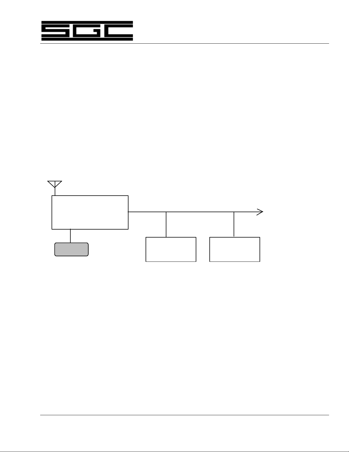
The basic SG-2000 is really two units, which may be easily separated. One unit is what
is called the Radio or RF unit. This contains the receiver and the transmitter's exciter
and linear power amplifier modules. In addition, it contains the SG-2000's main
microprocessor.
The second unit, normally supplied attached to the radio unit, is called the control head.
In it are audio amplifiers, the radio's frequency and channel displays, a keyboard to
control radio functions and another microprocessor which "talks" to the main radio
unit.
Audio wiring at 600 ohms plus
RS-422 (9600 baud) Serial Bus
SG-2000 RF Unit
To additional heads
(8 maximum)
Control Head Control Head
RS-232 (9600 baud)
Serial Port for
computer
One control head may be attached to
the SG-2000 RF unit. Up to seven
others may be located up to 50 meters
away from the RF unit using 10-conductor
cable.
4.1 Receiver Signal Path
The receiver section, located in the main radio unit, features signal up conversion (from
82 to 88 MHz) to achieve maximum image rejection and to allow wide band processing
of signals. Then the signal is converted down to 10.7 MHz where an extraordinarily
sharp crystal filter removes all unwanted signals, including strong unwanted signals
which have not been eliminated by the 82-88 MHz filters.
The 10.7 MHz signal is further amplified and is then decoded by one of the two
detectors in the radio. For single sideband, CW (Morse Code), and data operations, a
product detector is used. For AM, the SG-2000 provides one of the few "true AM"
detectors available today. This provides for extremely clear reception and excellent
The SGC Building, 13737 S.E. 26th St. Bellevue, WA. 98005 USA
©1995, SGC, Inc. TEL: (206) 746-6310 FAX: (206) 746-6384
Page 20

capture of signals in all modes.
SG-2000 MANUAL 13
The SGC Building, 13737 S.E. 26th St. Bellevue, WA. 98005 USA
©1995, SGC, Inc. TEL: (206) 746-6310 FAX: (206) 746-6384
Page 21

SG-2000 MANUAL 14
Once amplified to a standard level, the audio is sent to a jack on the back of the SG-2000
which allows for connection to a control head. In the control heads, the audio signal is
further amplified and processed.
A syllabic squelch circuit (which was pioneered by SGC in 1976) is used to turn off the
noise coming out of the speaker in the event that a signal is not being received.
The next step is a digital gate which controls the volume of the receiver by very rapidly
sampling the signal and passing only a certain number of samples — a number which
varies by the setting of the volume control on the front panel of the radio. Naturally,
this happens at speeds which you can not hear, so your ear hears smooth control of the
volume function.
4.2 Transmitter Signal Path
Pressing the push to talk button grounds the push-to-talk line, placing the SG-2000 in
the transmit mode. At the same time, the sound of your voice is shaped by an audio
amplifier in the control head. This is brought up to a standard level to be sent out the
transmit audio bus.
This line leaves the control head via the 10-conductor control head cable and returns to
the SG-2000 RF unit via the rear panel connector where the head plugs into the rear
panel of the radio.
Inside the radio, the audio signal is shaped and amplified. It is turned into an AM
signal which is then processed to remove the desired amount of carrier. This is
accomplished by a balanced modulator. In the single sideband mode, all of the carrier
is removed. If required, the carrier is reinserted for other modes.
In the AME (AM Equivalent) mode, 40-50 W of the carrier is reinserted. And if you are
operating in the A3A mode which is used for certain kinds of commercial radio work,
then you put back about 1/8th of the carrier, leaving just enough of the signal to act as
a "pilot carrier" for specialized receivers.
Next, the signal is amplified and passed through a crystal filter, where one sideband is
removed. This is done by offsetting the transmit frequency slightly. On one side of the
filter slope, the upper sideband is removed, while offsetting on the other side of the 10.7
MHz filter will remove the lower sideband.
When you are in the single sideband mode, you have now developed either the desired
upper or lower sideband filter at this point. From here on, the amplifiers which will be
processing the signal are called "linear amplifiers" because if they are not linear, they
will distort the signal, just like a non-linear audio amplifier would distort a signal on
your home stereo.
The 10.7 MHz single sideband signal is then converted up to 82-88 MHz, where
harmonics are eliminated by the helical filter. The output of the 82-88 MHz filter is
The SGC Building, 13737 S.E. 26th St. Bellevue, WA. 98005 USA
©1995, SGC, Inc. TEL: (206) 746-6310 FAX: (206) 746-6384
Page 22

SG-2000 MANUAL 15
mixed with the correct frequency developed by the synthesizer and is then amplified at
the operating frequency.
This amplification process involves several steps: a pre-driver, a driver, and a final
amplifier section which utilizes a splitter - combiner circuit
The pre-driver and the driver sections are very straight-forward in design. But the final
LPA (Linear Power Amplifier) deserves special note because it is very conservatively
constructed. This amplifier is made up of four transistors. While most designers will
use only two, SGC elected to use four for reliability and peak power performance.
Controlling the LPA is a circuit called ALC (Automatic Level Control) which adjusts the
operating conditions of the final amplifier to insure its operation is linear over a wide
range of conditions.
A broad band filter network then matches the high power signal to a 50 ohm output
impedance. This is then sent to the SG-230 Smartuner (which we highly recommend) or
a broad band antenna system such as the SG-103.
4.3 Control Circuits
The SG-2000 is a microprocessor controlled radio. Each of the control heads has a
microprocessor and talks to the microprocessor in the radio unit using the RS-422
communications protocol. This means that the control head may be placed as much as
50 meters away from the radio. Although not supported by SGC, many users of the
control heads have reported success at longer distances. As with all SGC specifications,
50 meters is a conservative number.
The microprocessor control codes, which are generated when the front panel push
buttons are pushed, are sent to the microprocessor in the radio unit which return
confirmation to the control head that the instructions have been acted upon. The head
microprocessor controls the display information and functions such as setting of
volume and squelch levels.
Each of the control heads has a unique device address which allows the microprocessors in the radio unit to send information as well as establish the intercom
address of the control head.
In the event that you wish to address the microprocessors on the radio unit directly,
you may use the RS-232 serial port which is located on the rear panel of the radio.
Any number of serial ports and heads may be used, as long as the total number of
device addresses does not exceed eight. Four control heads and four computers works
as well as one control head and seven computers.
The SGC Building, 13737 S.E. 26th St. Bellevue, WA. 98005 USA
©1995, SGC, Inc. TEL: (206) 746-6310 FAX: (206) 746-6384
Page 23

SG-2000 MANUAL 16
For more information on controlling the SG-2000 via computer, see Section 16.5 of this
manual regarding "Computer Networks - Serial Control" and the parts of Section 17.0
dealing with RS-232 software.
4.4 Control Heads
There are several design considerations behind the SG-2000 control head which you
should know about in order to appreciate the beauty of the architecture of the radio.
Our many years of manufacturing experience have taught us the value of absolute
reliability and of the importance of easy reparability in the field. Such philosophies as
designing in a 10-conductor control cable between our radios and remote heads rather
than a fiber optic cable is one example. SGC has learned that while fiber optics are an
excellent material, they are not easily reparable in the middle of the desert or ocean.
SGC products are designed for field repair and performance where well-engineered
products dramatically become evident.
4.5 SG-2000 Front Panel
The front of the SG-2000 controls all radio functions. All of the push buttons are
rubberized to provide good tactile response and to keep the radio highly resistant to
water and dust, two of the worst enemies of electronic equipment.
The LCD which displays the frequency is the largest available on a radio of this type.
The speaker is treated to resist moisture. The speaker grill is designed to prevent direct
spray from hitting the speaker.
Because the front panel has been ruggedly built, the advantage of mounting the more
sensitive radio unit elsewhere becomes apparent.
4.6 SG-2000 Rear Panel
A series of Jacks on the back of the SG-2000 provide access to radio features and
accessories. Most of these jacks are covered by a metal "U" bracket which is held in
place by three small Phillips head machine screws. If you ever have occasion to remove
this cover, it is important that it be replaced in order to provide physical protection for
the jacks.
Under the "U" bracket, from left to right, you will find a jack to plug in one of the family
of SGC's Smartuners. The next plug (J-301) presents audio input and output lines, plus
push-to-talk control. This is where Weatherfax, data controllers (such as an SGC
Telerex™ SITOR modem), and ALE units are plugged in.
The next two jacks are for plugging in two control heads. If you are using more than
one control head, one will plug in to the right hand head plug while a multiple plug
adapter unit plugs into the left control head jack and provides for up to seven
additional head connections.
The SGC Building, 13737 S.E. 26th St. Bellevue, WA. 98005 USA
©1995, SGC, Inc. TEL: (206) 746-6310 FAX: (206) 746-6384
Page 24

SG-2000 MANUAL 17
The last jack, J505, is used for connecting an external speaker. This is also the most
common connection for the Weatherfax.
In addition, just to the right of the "U" bracket is an RS-232 connector for computer
control of the SG-2000 radio, as explained later in this manual.
The SGC Building, 13737 S.E. 26th St. Bellevue, WA. 98005 USA
©1995, SGC, Inc. TEL: (206) 746-6310 FAX: (206) 746-6384
Page 25

SG-2000 MANUAL 18
5.0 SGC Family of Control Heads
The SG-2000 comes with the standard control head described throughout this manual.
In addition, there are six other control heads to choose from. These range from the small
remote mobile heads to the new PowerTalk™ head incorporating ADSP™ and SNS™
noise reduction capabilities.
5.1 Remote Mobile Heads
The four models of the remote mobile heads are designed to be used in conjunction
with the SG-2000. They have simplified control functions and a much smaller footprint.
They include the basic version, the aircraft version, the Exsel version and the remote
mobile head with ADSP™ noise reduction.
Please contact SGC for information on any of these optional heads.
5.2 PowerTalk™
Another optional control head is our newly released PowerTalk™ head. The
PowerTalk™ head is the same size as the standard remote head but with more
versatility, including the additional benefit of state of the art noise reduction circuits to
let the user filter out unwanted noise.
Please contact SGC for information on this model.
The SGC Building, 13737 S.E. 26th St. Bellevue, WA. 98005 USA
©1995, SGC, Inc. TEL: (206) 746-6310 FAX: (206) 746-6384
Page 26

SG-2000 MANUAL 19
6.0 SG-2000 Software and Accessories
This section lists various software options that are available for the MicroProcessor
controlled SG-2000. In the event that you own an SG-2000 and later wish to add
different software, such as the GPS software, Oil Rig software, Hong Kong software, or
other software as may be periodically published, please be advised that there is a
software update charge if the software is retrofitted into an existing radio.
6.1 GPS Software
Effective April 1, 1992, a special edition of the SG-2000 main microprocessor software
was published to meet the needs of the oil and gas exploration industry for a radio
which would not search the international emergency frequency, 2182 KHz, when the
radio is first turned on. The special software is now standard.
In addition, the SG-2000, which was adapted to differential GPS radio location service
in January of 1992 has special cooling modifications which allow it to operate under
severe service for unlimited time. The additional cooling systems may be ordered by
users who anticipate extended key down operations, including differential GPS, ALE,
SITOR/AMTOR/RTTY, and other data modes or plan to subject the SG-2000 to
unusually warm operations (such as desert vehicle installations).
6.2 Oil Platform Software
In May 1992, special software became available for the main MicroProcessor of the SG2000 which will allow the transmission of an emergency distress tone on all frequencies,
removing the normal limit of transmitting on only the international emergency
frequency, 2182 KHz. This was done at the request of oil exploration companies who
have been using the SG-2000 successfully in offshore oil exploration work and who are
required, because of international regulations, to both test and operate their emergency
distress beacons on frequencies in addition to the international 2 MHz band channel.
This software is now standard on the SG-2000. Press the shift function and emergency
buttons at the same time and the distress tone will be transmitted on the displayed
frequency.
Effective September 1, 1992, a special edition of the SG-2000 became available to users of
the SG-2000 in Hong Kong. Certain radio programming features are deleted in order
to meet Type Approval requirements of Hong Kong's G.P.O.
The SGC Building, 13737 S.E. 26th St. Bellevue, WA. 98005 USA
©1995, SGC, Inc. TEL: (206) 746-6310 FAX: (206) 746-6384
Page 27

SG-2000 MANUAL 20
7.0 Planning for Installation
Before installing the SG-2000, some pre-planning based on the capabilities and features
of this radio should be undertaken to ensure the best possible performance.
7.1 Location of Power Supplies
If you are installing your SG-2000 in a normal environment, such as a radio room of a
ship or in a room of an office building or home, placement of the power supply is not
critical as long as it is placed within 25 feet of the radio.
If you are installing the radio in a small boat, such as a cruising sailboat or an offshore
fishing boat, you may wish to consider an additional gel cell (sealed) battery for radio
operation. In this way, should the vessel take on water during a storm, the radio will
continue to be operational.
A good way to install such a system is to place the "radio battery" in the vicinity of the
radio and place an isolator between the radio battery and the rest of the battery system.
When connected to the vessel's main batteries, the radio battery will prevent the voltage
drop which may develop on long cable runs and will assure peak radio performance.
7.2 Control Head Placement
One of the advantages of SG-2000 / PRC-2250-MIL ownership is that control heads may
be placed anywhere within 50 meters of the radio unit. This provides a high degree of
installation flexibility. Consider some of the more common civilian uses.
Marine. On a vessel, you may want to have a control head located at the bridge,
navigation station, in the cockpit of the vessel and perhaps in staterooms. If you are
planning extended cruising on a typical ocean-going sailboat, usually two heads are
planned, one at the navigation station and another in a watertight case in the cockpit.
This is because in most serious ocean cruising, the owner's stateroom is not used as
often as the navigator's quarter berth, usually located very close to the navigation
station.
Mobile. Installation in a mobile environment is something else. If you are the only
radio operator on a small four wheel drive vehicle, such as a Chevrolet Geo Tracker,
which we use as a test bed for mobile systems, you will likely have a single control head
and this would be mounted on the dashboard using the 5-way suction cup mount.
If your mobile installation is larger, as in a bus or large recreational vehicle, you may
wish to have one control head in the rear area and another control head in the vehicle
The SGC Building, 13737 S.E. 26th St. Bellevue, WA. 98005 USA
©1995, SGC, Inc. TEL: (206) 746-6310 FAX: (206) 746-6384
Page 28

SG-2000 MANUAL 21
cockpit.
Aviation. Installation on aircraft presents an unusual challenge. In most cases, the
control head is mounted separately from the radio. This allows the radio unit to be
placed very close to the aircraft center of gravity.
7.3 Control Head Wiring
The control head cables which are used with the SG-2000 are designed for use in normal
conditions. This means that the cables are suitable for use in mobile and fixed
installations. Very high vibration environments and mounting in military situations
require special precautions.
In high vibration environments, wire chaffing must be avoided. Although it will take
more installation time, secure all wiring tightly to prevent movement. Once movement
begins, the protective covering of wiring can be quickly worn away. This is especially
true on a tug boat, for example, where vibration caused by the ship's large propeller can
cause 1/8" to 1/2" vibration and rates of 10 cycles per second or more. A shaking
control head wire moving even a fraction of an inch as it passes through a clamp will
ultimately fail.
Military installations require a different approach. The danger here is not vibration but
shrapnel. The most common methods used are either to bury the cable in a trench one
half meter deep, or, if the ground is hard or rocky, to place one or more layers of sand
bags over the cable.
7.4 External Speakers
The SG-2000 has no separate front panel headphone jack because the radio front panel
is weather-resistant and a headphone jack is just another hole that reduces the weather
resistance of the control head.
If you plan to use high impedance headphones, such as the type included in a telephone
handset, you will connect these to the radio via the microphone jack. On the other
hand, use of a low impedance headphone requires the use of the external speaker jack,
which is present on the rear panel of the SG-2000 main unit. The J-505 jack, the external
speaker jack, is also where a low-impedance Weatherfax modem may be connected.
The speaker jack on the rear of the SG-2000 is controlled like the front panel speaker.
In other words, when the SPK (speaker) is disabled on the control head, the remote
speaker which is wired in parallel with control head #1 speaker is also turned off.
Important Note: The rear panel speaker is only available
when the control head of the SG-2000 is attached to the
radio. This is because a separate speaker audio line is run
from the attached control head (where the audio amplifier is
The SGC Building, 13737 S.E. 26th St. Bellevue, WA. 98005 USA
©1995, SGC, Inc. TEL: (206) 746-6310 FAX: (206) 746-6384
Page 29

SG-2000 MANUAL 22
located) to the rear panel. When the head is detached, this
wiring is no longer available.
7.5 External Accessories
External accessory location should also be part of the planning process. If you are
planning to add external equipment such as a Weatherfax receive modem, a terminal
node controller (TNC) for amateur use, a commercial standard SITOR modem, such as
the SGC TELEREX™ system, or an ALE controller such as the SGC HardLink™ System,
provision for the mounting and operation of these items should be made at the time of
installation.
When planning the use of an external audio input to the SG-2000, make provision for
switching the external audio source on and off. This is necessary because the external
audio input feeding the SG-2000 is an unswitched bridge. In order to avoid transmitting
a microphone and line input signal (via J301) at the same time, you must be able to turn
off the line input source.
If you are planning to use some external units, you may need to plan additional space
for peripherals which may be required. As an example, the ALE controller requires a
video display terminal (or IBM-PC type computer) to access programming. This may
be a single unit terminal and keyboard, or it may be discrete keyboard and display
units.
A TNC may require a printer, a computer, or both. Provision for mounting of these
items is a good idea, especially if you will be adding them in the future.
Because of the larger number of options available, the subject of external radio
peripherals is covered in more depth later in this manual.
Look ahead — and plan for your future needs before you begin your installation!
The SGC Building, 13737 S.E. 26th St. Bellevue, WA. 98005 USA
©1995, SGC, Inc. TEL: (206) 746-6310 FAX: (206) 746-6384
Page 30

SG-2000 MANUAL 23
8.0 Radio Licenses
Finally, before we discuss installation of the SG-2000 radio, we should discuss licensing.
The operation of an SG-2000 generally requires two types of licensing. In the United
States, both a station license and an operator permit are issued by the Federal
Communications Commission. The SG-2000 is type accepted for use on both U.S.
marine and amateur bands. Therefore it is exempt from Part 97.11 (b) regulations
requiring separation of marine and ham radio equipment. Part 97.11 (b) prevents ham
radio equipment from being used on commercial bands but does not preclude use of
type-accepted commercial equipment on the ham bands.
8.1 Station Licenses
The U.S. F.C.C. issues licenses for the operation of many classes of radio stations. This
includes ham radio stations, commercial marine shore stations, shipboard stations and
those involving various kinds of mobile applications such as HF systems aboard
aircraft. There is an exception, however. Stations operating under the auspices of the
U.S. military and stations in the Military Affiliate Radio System (MARS), are exempt
from the licensing requirements of the F.C.C. but are subject to military rules. Most
countries have comparable regulations.
Generally, the charge, if any, for filing a station application is modest. If you are
planning to operate a U.S. commercial radio station, such as one aboard a fishing boat,
simply call the F.C.C. Regional Office (there are 12 regional offices located in the U.S.)
and ask them to send you the appropriate paperwork. Outside the U.S., check with
government authorities.
The same goes for pleasure craft such as cruisers, sports fishing boats, and sailboats.
The definition of "commercial station" means that the radio can be used for conduct of
"business."
It is generally a simple process to fill out the application form for a commercial license.
You may find that you will be asked for the SG-2000 Type Acceptance number. This is
not the model number of the SG-2000. It is the F.C.C.'s unique identifier which
references the official testing and approval paperwork.
On the license application, where "Type Acceptance Identifier" is requested please fill in
the following:
CFT8DKSG2000
The SGC Building, 13737 S.E. 26th St. Bellevue, WA. 98005 USA
©1995, SGC, Inc. TEL: (206) 746-6310 FAX: (206) 746-6384
Page 31

SG-2000 MANUAL 24
If you do not plan to operate aboard a ship, but have a need to communicate with
vessels on a regular commercial basis, you may qualify for a private coast station
license. The U.S. F.C.C. also has licenses available for specialized needs such as long
distance aviation communication.
In the United States the use of a commercial SSB station on land to communicate with
vessels is not allowed without proper licensing. To make application for a U.S. shore
station, you will need to complete F.C.C. forms 503, 155, and 753. The filing fee as of
1995 for form 503 is $120 while the filing fee for form 753 is $45. There is no charge for
form 155, which is a form to list your filing fees. This type of license is recommended
for marinas and fisheries services.
If you have a touch-tone telephone, you may order the appropriate license application
forms from the F.C.C.'s automated telephone forms request service through your local
office. The telephone number to call in the United States for current fee information is
(202) 418-0220.
A current printed copy of rules and regulations governing commercial marine
operations is available from Fair Press Services, P.O. Box 19352, 20th Street Station,
Washington, D.C., 20036-0352. Their phone number is (202) 463-7323. There is a charge
for this publication.
Amateur (ham) radio may not be used for the conduct of business and the operator of
the radio station is also licensed to repair the equipment. A test must be passed in order
to secure a ham radio license. Commercial stations may be serviced only by a person
holding the appropriate class of commercial radio license.
8.2 Operator Licenses
In the U.S., a radio operator license is required. The person operating a commercial
station aboard a pleasure craft, or any ocean going vessel under a certain tonnage, must
have at least an "Operator Permit" to use the radio of an appropriately licensed vessel.
It is simple to obtain the commercial Operator Permit document. It constitutes an
agreement to use the radio properly, use no profanity and to use the radio for no illegal
purposes. You sign your name, give your mailing address, and a few weeks later, an
operator license arrives.
If you intend repairing commercial radio equipment, the requirements become
stringent very quickly. A General Class Radiotelephone License is required to make
adjustments of equipment used in commercial service.
The F.C.C. has reduced the Morse Code requirements of a ham radio license and the
SG-2000 may be operated in the 10 meter amateur band with the new "Code Free"
license. Information about becoming a ham radio operator in the U.S. is available by
calling the National Amateur Radio Association, NARA, which maintains a toll-free
(800) telephone number.
The SGC Building, 13737 S.E. 26th St. Bellevue, WA. 98005 USA
©1995, SGC, Inc. TEL: (206) 746-6310 FAX: (206) 746-6384
Page 32

SG-2000 MANUAL 25
J-502 J-301 J-503 J-504 Ext Spk Oven
9.0 Installation
Your SG-2000/PRC-2250-MIL will provide superior communications under all
conditions if you take the time to plan and install the radio equipment for maximum
performance. Please read this section very carefully and implement as many of the
suggestions as possible to assure a trouble free installation, a superior transmit signal,
and clear reception.
This section of the manual will cover:
• General installation information and pin outs
• Control head installation and remote kits
• General comments on power supplies and antennas
• Specific mobile installation notes
• Specific marine installation suggestions
9.1 SG-2000 Rear Panel Connections
Protective cover secured by Philips head screws
RS-232
RF Output
Please note that your SG-2000 is shipped with all necessary connectors for the addition
of one of our Smartuner™ couplers and for installation of peripherals via the audio
input/output jack on the rear panel. You will see the connectors when you loosen the
Philips head screws which hold the protective sheet metal cover over the rear panel
connectors and remove the cover.
The SGC Building, 13737 S.E. 26th St. Bellevue, WA. 98005 USA
©1995, SGC, Inc. TEL: (206) 746-6310 FAX: (206) 746-6384
RF Ground
+ -GND
Page 33

SG-2000 MANUAL 26
J-502
From left to right, these jacks provide the following:
J-502 SG-230/SG-235 Smartuner™ connections
J-301 Aux. Audio input/output and PTT line
J-503 Remote control head or multiple head junction box
J-504 Remote control head or multiple head junction box (Head mounted on radio is
normally connected here.
Ext Spk External Speaker (or Weatherfax modem)
Oven Turns oven On-Off (Shipped with oven ON as default)
Pin outs of the external coupler jack and the Audio Input/Output jack are listed below.
These may also be found in the SG-2000 Technical Reference in appropriate schematics.
9.2 External Coupler Installation
Connector J-502 is used to connect the SG-2000 to an external coupler. Details are
shown in the diagram below:
Coupler Connections on rear
1 2 3
J-502 Pin 1: Coupler Ground. (Black wire from SG-230/SG-235)
Pin 2: Coupler +12 VDC. (Red wire from SG-230/SG-235)
Pin 3: Remote Tuned Indicator (Black/White wire from
SG-230/SG-235)
Do not connect the Red/White wire from the SG-230/SG-235 as
this wire is used to control coupler functions. See SG-230/SG-235
manuals for details on coupler control options via this wire.
panel of SG-2000
The SGC Building, 13737 S.E. 26th St. Bellevue, WA. 98005 USA
©1995, SGC, Inc. TEL: (206) 746-6310 FAX: (206) 746-6384
Page 34

SG-2000 MANUAL 27
9.2 External Modem, Weatherfax and High Seas Direct™
Connector J301 is used to connect the SG-2000 to an external modem. Details are shown
in the diagram below:
J-301
SG-2000 Rear panel
connections for external
modems, Telerex™ and
1 2 3 4
Pin 1: Audio input (600 ohm impedance) (From modem audio out)
Pin 2: Ground
Pin 3: Audio output (600 ohm impedance) (To medem audio input)
Pin 4: Push-To-Talk line (PTT line on modem if available)
Weatherfax
Weather fax modems: Connect Ground from modem to Pin 2 and audio input to
modem to Pin 3 of J-301. (Weather fax modems may also be connected to the external
speaker jack.) See Appendix for High Seas Direct connections. See page 61 for
connection to ALE controller and serial devices.
9.3 Continuous Duty Ratings
If you are planning to use your radio for intermittent voice communications,
continuous duty ratings are of no consequence. However, if you are planning to
transmit for long periods of time on a frequent basis, you should consider the duty cycle
and continuous ratings of components, ordering heavy duty cooling options if
necessary.
Duty cycle is a simple concept. If you are dealing with speech and you will be
transmitting about one quarter of the time, then the duty cycle of equipment is about
50%. However, if you are planning extended broadcast of information, speaking or
sending hours of information such as using a transceiver in the ARQ data transmission
mode, then continuous duty ratings are required.
All SGC equipment is conservatively rated. We use commercial service ratings for all of
our equipment and make continuous service available upon request. Continuous
Service is primarily a matter of adding additional cooling to a unit, as heat is the culprit
in most component failures when equipment is used in continuous service.
The SGC Building, 13737 S.E. 26th St. Bellevue, WA. 98005 USA
©1995, SGC, Inc. TEL: (206) 746-6310 FAX: (206) 746-6384
Page 35

SG-2000 MANUAL 28
SGC Part Number 51-81 is an internal fan option which consists of a muffin type fan
which is controlled by a temperature sensor inside the radio. With the fan on, air enters
the bottom of the radio and is exhausted through a special louvered top cover and slots
on the rear panel.
When using the continuous duty option on the SG-2000, power output is limited to 110120 watts continuous. Maintain an unrestricted air flow area of at least 1 inch around
all surfaces of the radio.
SGC Part Number 52-90 (Rack mount kit for SG-2000) has fans built in and is also suited
for continuous duty operation. Field installation instructions for the rack mount follow.
Note: If you are using your SG-2000 in continuous duty
operation, you must be certain that the power supply you
plan to use is suited to continuous operation. We recommend the SGC PS-30 or PS-50 power supplies, Part Numbers
53-04 and 53-05, for continuous duty commercial service.
9.4 Rack Mount Kit Installation (Part No. 52-90)
The SG-2000 may be mounted in a standard 19" equipment rack. This installation may
be performed in the field using the following procedure:
TOOLS REQUIRED:
Philips Screwdriver #2 Point
Philips Screwdriver #1 Point
Nut Driver 1/4"
Flat Blade Screwdriver 1/8"
Nut Driver 5/16"
Open End Wrench 1/4"
Flat Blade Screwdriver 3/8"
Open End Wrench 7/16"
The SGC Building, 13737 S.E. 26th St. Bellevue, WA. 98005 USA
©1995, SGC, Inc. TEL: (206) 746-6310 FAX: (206) 746-6384
Page 36

SG-2000 MANUAL 29
TEST EQUIPMENT REQUIRED: None
CAUTIONS:
• Power must be disconnected from radio.
• Do not over tighten screws which will strip heads.
Installation Procedure
1. Remove top cover-secured by six black #6 Philips Head
screws-set cover and screws aside.
2. Remove bottom cover-secured by six black #6 Philips Head
screws-set cover and screws aside.
3. Remove rear panel connector cover-secured by three #4
Philips Head screws-set cover and screws aside.
4. Remove rear panel control head cable clamp-secured by one
#4 Philips Head screw-set screw and clamp aside.
5. Unplug control head cable connector (10-position) from rear
panel.
6. Remove control head as follows:
a. Remove two #6 Philips Flathead screws from either side
panel (located towards front of radio)
b. Remove two #6 Philips Flathead screws from other side
panel (located towards front of radio)
c. Lift control head cable up and out of cable U-Channel.
d. Gently pull control head/cable assembly forward-set this
assembly aside.
7. Install the fan option connector assembly supplied by
plugging the connector into J16 with the Green wire to Pin 1.
8. Set the radio (upside up) into the tray assembly. Rear of
radio should face power cables.
9. Lift the rear of the radio (if necessary) and install the DC
power wires to the radio DC terminal strip; red to "+", black
to "-" set radio back down (if necessary).
10. Secure radio to bottom cover. Use four #6 black Philips
Head screws removed in step #2.
The SGC Building, 13737 S.E. 26th St. Bellevue, WA. 98005 USA
©1995, SGC, Inc. TEL: (206) 746-6310 FAX: (206) 746-6384
Page 37

SG-2000 MANUAL 30
11. Install RF ground jumper braid onto radio rear panel RF
ground bolt.
12. Install RF coax jumper into radio rear panel RF in/out
connector-set the radio/tray assembly aside.
13. Install the control head rear panel as follows;
a. Unplug the control head cable connector (10-position) from
the control head display board assembly-set the cable
assembly aside.
b. Remove either head mounting bracket by removing two
Philips Head screws.
c. Remove other head mounting bracket by removing two
Philips Head screws.
d. Install the four longer threaded stand-offs, SGC part # 965-
913 (supplied), into the inserts from which the screws were
removed in steps B and C above.
e. Replace four #4 Philips Head microprocessor assembly
mounting screws with the four shorter threaded stand-offs,
SGC part #965-908 (supplied).
f. Remove control head connector (10-position) from control
head cable.
g. Pass the control head cable through the Heyco watertight
fitting on the control head rear panel (supplied). Do not
tighten the Heyco.
h. Re-install connector removed in Step F (see illustration
supplied).
i. Install control head connector onto control head display
board assembly (from step A)
j. Attach control head rear panel to control head using eight #4
Philips Flathead screws (supplied).
k. Tighten Heyco
17. Attach control head assembly to rack mount front panel
using four each #8 nuts (supplied attached to control head
rear panel).
18. Attach control head/front panel assembly to tray assembly
using 7 each #4 lock washers and #4 nuts (supplied attached
The SGC Building, 13737 S.E. 26th St. Bellevue, WA. 98005 USA
©1995, SGC, Inc. TEL: (206) 746-6310 FAX: (206) 746-6384
Page 38

SG-2000 MANUAL 31
to front panel)
The SGC Building, 13737 S.E. 26th St. Bellevue, WA. 98005 USA
©1995, SGC, Inc. TEL: (206) 746-6310 FAX: (206) 746-6384
Page 39

SG-2000 MANUAL 32
19. Re-install control head cable connector (10-position) into rear
panel (from step #5)
20. Re-install cable clamp using one #4 Philips Head screws
(from step #4).
21. Re-install rear panel connector cover using three #4 Philips
Head screws (from step #3).
22. Install louvered top cover (supplied) using six #6 black
Philips Head screws (from step 2).
This concludes the Rack Mount Retrofit Procedure.
9.5 Control Head Installations
The SG-2000 is a multiple control head radio. There are two ways to obtain a remote
head configuration. First is to remove the control head supplied on the SG-2000.
Second is to plug in additional control heads. While most people order their SG-2000
with the Remote Head Kit installed, this item may be installed in the field through the
following procedure:
9.6 Remote Head Kit Installation (Part No. 04-12)
As supplied, the SG-2000 comes with a control panel attached to the front of the radio.
As an option, a remote head kit, part number 04-12 may be installed, extending the
control head 16 feet from the radio and supplying a gimbal mount. Installation takes 10
minutes.
TOOLS REQUIRED: Philips Head Screwdriver
TEST EQUIPMENT REQUIRED: None
CAUTIONS:
• Power must be disconnected from radio for this
procedure.
• Use care not to over tighten screws and strip threads.
Installation Procedure
1. Locate and remove the wiring shield on the back of the SG-2000. This
shield, which runs horizontally across the back of the radio, is held in
place by three Phillips head screws. Unplug the control head number
1 cable.
2. Locate and remove the six black Phillips head screws which secure the
top cover to the SG-2000 and remove the top cover. Two screws are
located on each side of the radio and two screws are located on the top
The SGC Building, 13737 S.E. 26th St. Bellevue, WA. 98005 USA
©1995, SGC, Inc. TEL: (206) 746-6310 FAX: (206) 746-6384
Page 40

SG-2000 MANUAL 33
of the radio.
3. Turn radio upside down on a stable surface. Remove the six screws
which hold the bottom cover of the SG-2000 and remove the bottom
cover. Two screws are located on each side of the radio and two
screws are located on the bottom of the radio.
Turn radio right side up.
4. Locate and remove four Phillips head screws which hold the control
head in place. (Two on each side.)
5. Carefully slide the control head forward to remove it from the radio
body.
6. Remove control head cable from wire race in radio body. Remove
external speaker jack feed. Note: External speaker jack only functions
if a head is attached to SG-2000 body.
7. Turn radio upside down. Reinstall bottom cover. Secure with six
Phillips head screws.
8. Turn radio right side up. Install top cover and secure with six Phillips
head screws.
(Optional: Install Remote head in desired location and route cable to
radio unit.)
9. Plug remote control head into rear panel connector of SG-2000.
Carefully install cable shield over the control wire and secure shield
with three Phillips head screws. Cable clamp on left side of rear panel
is not used with external control head.
Installation of the remote control head is now complete.
The SGC Building, 13737 S.E. 26th St. Bellevue, WA. 98005 USA
©1995, SGC, Inc. TEL: (206) 746-6310 FAX: (206) 746-6384
Page 41

SG-2000 MANUAL 34
9.7 Additional Control Heads (Part No. 04-11)
Additional control heads may be added to the SG-2000 via the 10-pin connector located
under the protective cover on the rear panel of the radio. In the event more than one
additional control head is desired, a junction box is used. Please refer to the following
diagram:
REAR PANEL CONNECTION FOR ADDITIONAL CONTROL HEADS
SG-2000
Rear
J-503
Single control head
Junction Box for Additional Control Heads
The SGC Building, 13737 S.E. 26th St. Bellevue, WA. 98005 USA
©1995, SGC, Inc. TEL: (206) 746-6310 FAX: (206) 746-6384
Page 42

SG-2000 MANUAL 35
9.8 Remote Head Cable Extension
In the event that you need to extend the length of the control cable on the head of an
SG-2000, two steps need to occur:
First, you have to remove the control head from the radio. The procedure above will
allow you to remove the control head.
Second, you need to replace the existing cable with a longer one.
The cable which connects the SG-2000 to the control head(s) is attached to the units
using standard connectors at each end. In this manner, the length of the control cable
may be easily changed. Carefully unplug the existing cable assembly from the control
head and radio and replace it with the desired length.
While we recommend that you use the control head wiring supplied by SGC, you may
use any other 10-conductor shielded wiring. Remember, however, that the length of the
cable run to a remote head is partly determined by the quality of wiring used. If you
use very small conductors and try to exceed the 50 meter RS-422 standard distance, you
may be disappointed. If, on the other hand, you choose suitably large conductors, (#18
or larger), you will achieve excellent results beyond 50 meters.
The SGC Building, 13737 S.E. 26th St. Bellevue, WA. 98005 USA
©1995, SGC, Inc. TEL: (206) 746-6310 FAX: (206) 746-6384
Page 43

SG-2000 MANUAL 36
10.0 Power Supplies
Many power sources can be used with the SG-2000. Among these are:
• Transformer or regulated power supplies from AC mains
• Battery systems
• Solar Systems
• Wind Powered Systems
All modern transceivers run on 12 Volts DC. With the exception of AC mains power
supplies, all other systems supply DC suitable to run a radio. However, various
regulators may be necessary, because regulation of solar and wind powered systems is
difficult.
Another important consideration, how power is moved from the power supply to the
radio, can have a very high impact on ultimate radio performance, especially when
transmitting.
10.1 Cabling
Regardless of the type of power supply used, you should design cabling from the
power supply to the radio to minimize voltage drop. This drop occurs because wire is
not a perfect conductor of electricity. The longer the distance between a power supply
and a radio, the greater the voltage drop will be.
SGC recommends placing a power supply no more than 25 feet from a radio. There are
two reasons for this:
First. The voltage drop experienced over 25 feet, even when large conductor cabling is
used, is not acceptable.
Second. The longer the power cabling, the more chance that it will fail due to any
number of unforeseen circumstances.
When electricity flows from the power supply to the radio at low current levels, the
internal resistance of the wire has little effect. But as current increases, the voltage drop
becomes more pronounced.
Now apply that to your power wiring: turn on the radio at a low power level, such as
the receive mode where little power is drawn, and things will likely be just fine with
number 16 or number 14 wire at 25 feet; but turn on the transmitter, where lots of
The SGC Building, 13737 S.E. 26th St. Bellevue, WA. 98005 USA
©1995, SGC, Inc. TEL: (206) 746-6310 FAX: (206) 746-6384
Page 44

SG-2000 MANUAL 37
power is drawn, and nothing may work correctly because the voltage will drop
dramatically.
Let's consider wire sizes between the power source and the radio. At 25 feet we
recommend number 6 wire. At 12 feet we also recommend number 6. At 2 feet we
recommend number 8, but we use number 6 because its more in line with our practice
of building generous margins into all SGC products.
10.2 AC Power Supplies
There are two ways to convert high voltages AC from either 110 or 220 Volts to DC
voltages suitable for operation of an HF radio, generally 12 Volts DC: conventional
transformer-rectifier power supplies and switching type power supplies.
SGC does not recommend switching type power supplies for continuous commercial
service for two reasons: First, unless the switching power supply is of exceptional
design and properly installed, it will generate RF “hash” which will create a high local
noise level. Second, switching type power supplies of inferior design are not as capable
of continuous duty operation.
Some switching power supplies are quite good. Unfortunately, they are also very
expensive and not as cost effective as a transformer-rectifier type power supply.
10.3 Transformer-Rectifier Supplies
Transformer-rectifier power supplies are by far the most reliable available. They are
able to operate over a wide range of input voltages and offer resistance to failure under
periodic overload conditions which would cause a switching type supply to fail.
Supply voltages for such power supplies are generally 110 and 220 volts AC with a
frequency of either 50 or 60 Hz. Many aircraft also have 400 Hz AC available from their
engine-driven alternators, but in these instances, it is usually better to power equipment
from 24 volts (generally available on aircraft) than install a power supply to operate
equipment from the 400 Hz AC power source.
High peak current is an important consideration if you are planning to operate in the
voice mode. But if you are planning to operate in the data mode or will be using the
transmitter on a more continuous basis, output capacity is less a factor than how
heavily-built the transformer in the power supply is.
SGC does not generally recommend switching type power supplies in either a mobile or
a base station installation for these two reasons: first, switching power supplies easily
generate noise from the switching circuitry; second, under heavy loads, the switching
type power supplies tend to stall and cause an interruption of power to your radio.
The SGC Building, 13737 S.E. 26th St. Bellevue, WA. 98005 USA
©1995, SGC, Inc. TEL: (206) 746-6310 FAX: (206) 746-6384
Page 45

SG-2000 MANUAL 38
10.4 Mobile Power Supplies
In virtually all mobile power supplies, the source of power is the alternator or generator
system of a vehicle and the battery. There are several principals of good design that
come into play in the mobile environment which you should consider when going
mobile on HF.
First, HF takes a lot of power on transmit. While you can use a single battery to power
both the vehicle and the radio, SGC recommends the installation of an additional
battery in all cases where this is practical. The reason for this is that the output voltage
from a battery drops as the load increases. The more reserve current capacity, the lower
the voltage drop under high intermittent power demands.
Some vehicles operate on 24 volt power in the mobile and marine services. There are
two approaches which can be taken. First, you can put in a 24 volt to 12 volt converter.
This is usually expensive. A much less expensive approach is to look for a 24 volt
system which uses two 12 volt batteries in series. If you are fortunate to find this type of
installation, simply use the 12 volt battery which has its negative post tied to ground
and the positive lug at 12 volts above ground. Never use the battery on the other half!
In mobile operations, the biggest problem you will run into will be noise. While noise
sources are easily found in fixed locations, in the mobile environment, including marine
applications, noise sources may vary depending on engine speed and other variables.
Mobile power sources are notoriously noisy. Generators and alternators are only part
of the problem which you will encounter. The presence of ignition sources including
the coil, distributor and the spark plugs complicates matters. The best solution is to use
a diesel engine and eliminate the ignition issue entirely.
When you are installing an HF system in a mobile setting, one of the best pieces of
troubleshooting equipment you'll find is a small portable AM broadcast band transistor
radio. With this radio, tuned to the highest end of its range (usually around 1600 KHz),
you can use it as a hand-held noise probe to quickly identify sources of noise.
Good design practice dictates putting capacitors across the alternator or generator
output and across the primary leads to the coil/distributor and at fans and other
electrically operated devices. We've even found cases where power windows in a
vehicle would cause RF “hash” on receive. The point is that you almost never have too
many capacitors.
Ignition wire can be both a source of grief and a source of joy, depending on the vehicle.
Most vehicles in North America come with resistor-type ignition wiring. This wiring
has about 10 K ohms of resistance from the distributor to the spark plug. If you have a
vehicle with solid ignition wiring and you experience RF “hash,” a 10 K ohm, 10 watt
The SGC Building, 13737 S.E. 26th St. Bellevue, WA. 98005 USA
©1995, SGC, Inc. TEL: (206) 746-6310 FAX: (206) 746-6384
Page 46

SG-2000 MANUAL 39
resistor in series with the ignition wire and installed at the distributor will usually help
matters.
When you are tracking down ignition noise near a gasoline engine, you may find that
the distributor is a major source of noise. Generally, you can't use capacitors to reduce
noise from a distributor because the noise is coming from the spark generated for
ignition. Adding enough capacitance to change the rise time of the spark voltage to a
lower value which will reduce RF “hash” delays the time the spark will gap inside the
engine. This means that timing will be changed (delayed) if a purely capacitive answer
is sought.
Here, shielding of the distributor and wiring is likely to be the best answer. Even when
you put shielding on the outside of ignition wires, you create a capacitor. Depending
on the type of ignition system and the length of the spark plug wires, you may find
timing retarded to the point that an engine will not deliver good performance without
adjustment of timing.
10.5 Solar Powered Chargers
Not much needs to be said about solar charging systems except that good design
practice needs to be followed to provide operation under all conditions which are
expected to be encountered.
The most critical element in design of an HF solar power system is local weather
conditions. If you are designing a solar system for an area where there will be little
sunlight for many days in a row, then a large battery system will be needed along with
additional solar panels. On the other hand, if you are designing for an area where there
is a lot of sunshine at all times of the year, then you will need fewer panels; in some
cases two 53-watt panels and one good gel cell battery will be sufficient.
Seasonality is also a consideration. Obviously, in the high Arctic, solar power is ideal
for the month or two during the year when the sun never goes down. But in the other
months, solar power is not a good idea. Hence, another consideration should be
latitude where a solar system will be installed and a calculation of the number of hours
of daylight which will be available.
The kind of regulator which is selected to control the output of the solar panel(s) is very
important. It should operate over a wide range of loads and should continue to provide
trickle charging to keep the battery system charged to its fullest between operating
sessions.
The SGC Building, 13737 S.E. 26th St. Bellevue, WA. 98005 USA
©1995, SGC, Inc. TEL: (206) 746-6310 FAX: (206) 746-6384
Page 47

SG-2000 MANUAL 40
11.0 Antenna Systems
The function of an antenna is to couple radio energy into space and the most important
factor in considering an antenna is to realize an inescapable law of physics: big antennas
are capable of doing a better job of coupling energy into space than are small antennas
at any given frequency.
The single most important formula to know in dealing with antennas is that the size of a
1/2 wavelength dipole antenna is:
468 divided by the frequency in Megahertz.
(468/F MHz = 1/2 Wave in feet)
The second most important fact to remember is that, due to space considerations, oftentimes the size of a MF or an HF antenna is a quarter wavelength.
This means for example that at 10 MHz (The frequency of the US National Bureau of
Standards time and frequency standard stations WWV and WWVH) a half wavelength
is 46.8 feet and a quarter wavelength is 23.4 feet. By the same token a broadcast station
at 1 MHz (1000 KHz) has a quarter wavelength of 234 feet while a quarter wavelength
at 100 MHz in the FM broadcast band is only 2.34 feet.
An antenna does not have to be a physical quarter wavelength in order to work
efficiently: shortened antennas can be used. But any time an antenna is less than a
physical quarter wavelength it will not have as much gain — or efficiency of coupling
energy into space — as will a larger antenna. Use of a high performance antenna
coupler, such as an SG-230 Smartuner™, Smartuner™ Pro, or SG-235, will improve
performance of all antennas dramatically.
Short antennas represent some compromise. However, in many cases they can give
good performance, especially in applications such as mobile HF work and in loops
which are used where space is limited and noise levels are high. In other words, there
are antennas which will provide performance better than a quarter wavelength antenna
for a specific application.
Antenna length is not the only consideration. Another important factor is antenna wire
size
The SGC Building, 13737 S.E. 26th St. Bellevue, WA. 98005 USA
©1995, SGC, Inc. TEL: (206) 746-6310 FAX: (206) 746-6384
Page 48

SG-2000 MANUAL 41
11.1 Antenna Wire Size
Antennas are working their best when current in the antenna is high. A large wire will
radiate more efficiently than a small wire.
Stranded wires will also radiate better than solid wires. Because AC electrical voltages
are carried by the surface of a wire, stranded wire has more surface area and therefore
radiates more efficiently.
If you wanted to design a good half wavelength antenna for HF work, you would
select the largest wire possible because you know that at power levels of 150 watts and
up, the difference between number 14 wire and number 6 wire can be as much as 3 dB.
This means that just changing the wire size can double the effective radiated power
coming from an antenna.
If you want to get the effect of a higher power transmitter, just increase the size of
antenna wire. You can easily make a 150 watt radio perform like a 300 watt radio.
Another consideration with any antenna is the size and location of the counterpoise, the
electrical “mirror” of an antenna. In the case of a center-fed dipole, it is the "cold" end
of the dipole. On a vertical antenna, it is the ground system or the metal of a vehicle
which is acting as a mirror. The counterpoise must be larger than the antenna or the
system will not radiate effectively.
If you are ever working on an HF radio and you get RF “bites” when your hand touches
the equipment or your lips touch a metallic microphone, you likely have a situation
where the antenna is electrically "bigger" than the ground or counterpoise and so the
counterpoise is radiating.
The height of an antenna over ground or counterpoise varies by the kind of antenna
which is in use because this determines the take-off angle of the radiated signal. This is
not an issue with vertical antennas as much as with horizontally mounted antennas.
In a vertical antenna the ground, or counterpoise, is parallel to the surface of the earth.
Since the maximum radiation from vertical antennas is shaped something like a donut
with a pencil through it with the pencil representing the antenna, you can see how the
ground (which would slice the donut shaped RF pattern horizontally) would have little
effect on take-off angle.
When you turn the antenna (yes, and that donut and pencil) over on its side to
represent a horizontally mounted antenna, the donut becomes two half donuts lying on
the surface of the earth. The take off angle — which is the amount of energy going
toward the horizon — is lowered as the horizontal antenna moves up from ground
level. The angle approaches its minimum one wavelength or more above ground.
The SGC Building, 13737 S.E. 26th St. Bellevue, WA. 98005 USA
©1995, SGC, Inc. TEL: (206) 746-6310 FAX: (206) 746-6384
Page 49

SG-2000 MANUAL 42
There are also some other effects on antenna performance when it is raised up from
ground. At low levels, down close to the ground, an antenna will exhibit a certain
impedance (usually lower than at higher elevations). As a dipole antenna is moved up
from the ground, it will go to a higher impedance until it settles at between 50 and 72
ohms at one wavelength over the ground.
Radio signals are polarized. This means that a signal coming from a vertical antenna
will be best received by a vertical antenna, provided that the antennas are of equal gain.
This means that even though a quarter wavelength vertical will likely be heard at
distance better on a similar vertical than on a horizontal dipole antenna, a horizontal
antenna array with substantial gain, such as a log periodic beam, will receive the signal
better than either the vertical or horizontal dipole. Antenna gain is the best investment
you can make because it works for you both in the transmit mode and in the receive
mode.
A couple of other comments about polarization: most of the noises which you hear
from over the horizon are vertically polarized so a horizontally polarized antenna will
be quieter. And there are, in addition, circularly polarized antennas such as large delta
loop antennas on low frequencies and quad type loops on the higher HF frequencies.
11.2 Near Vertical Incidence Skywave
Not all HF SSB work is done at transcontinental or intercontinental range. There is
often a need to operate at close-in distances of less than 400 km. HF can provide a good
solution for this type of communications. The technique is called Near Vertical Incident
Skywave propagation (NVIS).
The NVIS antenna works on principles opposite those which lead to good long distance
communications. Instead of sending maximum signal toward the horizon to hit the
ionosphere at a shallow angle hundreds of miles away, the objective in NVIS antennas
is to bounce almost straight up and come back down. While this antenna works great in
the daytime and at short distances, it is very poor at night or when longer distances are
being attempted.
NVIS antennas are generally low frequency antennas which operate from 2 to 7 MHz.
The effect on performance of NVIS and groundwave radiation at these frequencies can
only be established over a period of several days and several nights of operating.
11.3 Base Station and Fixed Antennas
With the discussion of some basic antenna principles in mind, you must decide what
kind of antenna to install for a fixed station. If distances to be communicated are long,
say over 1,000 Km, then a low angle of radiation is desired. The antennas which work
best for these purposes are either vertical antennas, dipoles oriented so that their major
lobe is in the desired direction (dipole lobes are perpendicular to the wire axis), or beam
antennas.
The SGC Building, 13737 S.E. 26th St. Bellevue, WA. 98005 USA
©1995, SGC, Inc. TEL: (206) 746-6310 FAX: (206) 746-6384
Page 50

SG-2000 MANUAL 43
At closer distances, inverted “L” wire antennas with a suitable high efficiency coupler
such as an SG-230 work very well. Dipoles, folded dipoles, and any other efficient 50
ohm antenna will work well at distances up to 1,000 Km.
Loop antennas are best for receiving because they are quieted by presenting a short
circuit to local noise pulses from industrial and commercial sources. But loop antennas
need to be very large at low frequencies to radiate efficiently.
The basic design rule for all fixed antennas is “If you have real estate — use it.” The
bigger the antenna — within reason — the more effective the antenna will be. Also,
except for NVIS applications, the higher the antenna, the better.
11.4 Antenna Feed Lines
You have to get power from the transmitter or transceiver to an antenna. To do this
you need a transmission line. A lot of “old timers” in HF believe to this day that high
impedance feedlines are best, but science doesn't agree with that point of view.
High impedance feedlines worked so well in the “old days” because tube type
transmitters had a final amplifier impedance of between 5,000 and 10,000 ohms.
Matching 5,000 ohms to a 500 ohm feedline meant a transformation of 10 to 1 — a
simple task for a transformer — which is what the output section of a transmitter is.
Changing the match to 50 ohm lines meant the matching transformer had to match 100
to 1 — a more difficult chore with the opportunity for a lot more loss if everything
wasn't properly adjusted.
With the advent of solid state radio equipment, the rules turned upside down. Now, a
final transistor LPA (Linear Power Amplifier) impedance runs in the neighborhood of 1
to 2 ohms. This means that a 500 ohm line would be a 1- to -500 or 1- to -250 match —
and not very good odds of getting things just right. The 50 ohm feedline represents a 1to -25 or a 1- to -50 match — which is easily and safely designed.
Given this little bit of history, if you do not have the luxury of having a transmitter right
at the antenna site — and this usually only happens in the case of AM broadcast band
Medium Wave transmitters — then the best way to get RF from point "A" to point "B" is
via 50 ohm impedance coaxial cable.
The SGC Building, 13737 S.E. 26th St. Bellevue, WA. 98005 USA
©1995, SGC, Inc. TEL: (206) 746-6310 FAX: (206) 746-6384
Page 51

SG-2000 MANUAL 44
11.5 Antenna Couplers
If the transmitter and the feedline are both 50 ohms and the antenna is 100 ohms, a
mismatch will occur. A portion of the power coming from the transmitter which should
be radiated by the antenna will be "reflected" back toward the transmitter. As this
occurs, standing waves develop on the feedline. The ratio of the peak voltage going to
the antenna and the measured peak voltage reflected back to the transmitter by an
unmatched condition is called Voltage Standing Wave Ratio (VSWR).
When a VSWR (SWR for short) exceeds about 2 to 1, the HF transmitter will reduce
power to reduce stress on components. Reflected power has nowhere to go but to be
turned into heat. This heat can be dissipated by the coax feedline or it can be dissipated
by components in the output circuit of a transmitter. Either way, one of the rules of HF
equipment is “heat is bad!” So it is in SWR considerations.
You can reduce SWR either by changing the length of the antenna or by introducing a
matching network which will precisely match the conditions of the antenna to the
requirements of the feedline: an antenna coupler.
If the SWR presented by an antenna is less than 2— to —1, the addition of an antenna
coupler will make only a modest improvement in the transfer of energy. If the SWR
exceeds 2 to 1, however, the results can be dramatic from this one piece of equipment.
One of the problems with earlier coupler designs was that the coupler was either a
manual tuning device, such as a series of capacitors and roller inductors which had
knobs and cranks on them, or the job was handled by large servo-motors which read
voltages and made adjustments accordingly. But neither of these approaches was good
enough for the new technology which has become available and which includes the
next generation of adaptive HF radio controllers.
So SGC began to build computer controlled antenna couplers including the SG-230 and
SG-235 Smartuner™ couplers. SGC began building the servo-motor type automatic
couplers in 1975 so the transition to a computerized coupler with extremely fast retune
times was a logical development. The SGC Smartuner™ is widely acknowledged as the
finest antenna coupler available. We encourage you to use a Smartuner™ with the SG2000 because few antennas will provide an even load over the wide range of frequencies
covered by the SG-2000.
11.6 Mobile Antennas
The standard whip antenna used in the HF environment has a brief but interesting
history related to the Citizen's Band radio craze which swept the United States in the
1970's. The "generic" 108 inch long stainless steel whip, while it could be mounted in
such a way as to operate at 27 MHz without any coils, traps or matching network, it is
The SGC Building, 13737 S.E. 26th St. Bellevue, WA. 98005 USA
©1995, SGC, Inc. TEL: (206) 746-6310 FAX: (206) 746-6384
Page 52

SG-2000 MANUAL 45
not generally well built and may fail when used in commercial service because of its
poor base insulation and its lack of a shock absorbing base. It just whips around and
doesn't stay where it belongs.
Single element commercial heavy duty antennas such as those made by Hustler are a
step in the right direction for lower frequency HF work. Although some companies still
sell 108" stainless steel whip-based products, the professional HF person will always
choose a center or top loaded whip antenna if a single frequency is to be used.
When a series of frequencies spread across the spectrum is to be used, the professional
answer is either to put up with changing loading coils or to put in a continuously
loaded helically-wound antenna. This provides a reasonable load to a good antenna
coupler at all frequencies from about 1.8 to 30 MHz.
SGC is the only manufacturer to add the good attributes of a 108" whip (which
performs well at the 20 MHz range and above) with the high performance of a helical
antenna that performs well at the lower frequencies.
The use of an antenna coupler is required on all but the most carefully matched centerand top-loaded mobile whip antennas which present close to a 50 ohm match to the
antenna lead.
Although it is tempting to use both a coupler and a center loaded antenna, the center
loading element of a loaded antenna already acts as an RF choke at high frequencies.
Thus, it actually reduces the effective length of an antenna if used on a high band.
11.7 QMS Recommended for Mobile Use
SGC engineers have discovered that the QMS-II antenna system, comprising an SGC
coupler (the SG-230 Smartuner™ or the two new couplers — the SG-230 Smartuner™
Pro and the SG-235) mounted in a QMS and driving the SG-303 high performance whip
antenna will typically yield substantial improvement in gain over a conventional 1.8 to
30 MHz HF mobile antenna installation. When we start making claims of 20 dB, a lot of
people (maybe even you) will be skeptical. So let us show you how you can get a
significant increase in gain by simply using a QMS compared with any other 1.8 to 30
MHz system:
1. Most antennas are so heavy that they are mounted on the bumper of a vehicle.
Because of this location, about a third of the antenna is less than a foot from the
grounded bodysheet metal. This is equivalent to a capacitor of 25 to 100 pico Farads
shorting your antenna. QMS, mounted high on the side of the vehicle, gains 3 to 6
dB.
2. Body sheet metal prevents the antenna from radiating evenly. It shields the signal
in certain directions and causes distorted radiation lobes. QMS gains another 3 to 6
dB.
The SGC Building, 13737 S.E. 26th St. Bellevue, WA. 98005 USA
©1995, SGC, Inc. TEL: (206) 746-6310 FAX: (206) 746-6384
Page 53

SG-2000 MANUAL 46
3. If an antenna coupler is mounted in the trunk of a vehicle, it will have 1 to 2 feet of
HV cable going to the antenna on the outside. With as short as a 1-foot lead wire,
and using a 9-foot antenna, this means that fully 10% of the antenna system is inside
the vehicle where it won't transmit or receive. It also creates another 10 to 100 pico
Farads of capacitance which results in more losses! With QMS, you'll pick up 3-6
dB.
4. Wire size of the antenna counts. Almost the resonant type antennas are wound
with number 22 wire. The SG-303, the antenna used with the QMS, is wound with
3 millimeter wide tape wire strap — equivalent to AWG # 4 wire. With a 100-watt
class transceiver, you'll develop 3 to 7 amps (or more) of RF on the antenna, and 7
amps through #22 wire represents major losses. The QMS with the SG-303 antenna
scores another 3-6 dB advantage.
5. The SG-303, is actually two antennas in a single casing. A single rod equivalent to
the conventional stainless steel whip element resonates at about 22 MHz; plus a
helically wound element resonates at about 10 MHz. This means that on lower
frequencies, those under 20 MHz or so, the SG-303 will vastly outperform a
conventional 9 foot whip. Chalk up several more dB for QMS.
6. Some hams use the so-called “antenna tuner” built into some radios and feed their
antennas directly with coax. The problem is that with a non-resonant antenna, a
very high SWR exists on the feedline between the radio and antenna even if you
get a low SWR reading with a built in tuner. Built-in tuners are nothing more than
trimmers. The QMS system puts a true coupler right at the antenna. When your
feedline SWR is above 4 to 1 you have effectively put 29 pico Farads per foot
capacitance to ground! That's at least 3 to 6 dB more gain for QMS!
GAIN ADVANTAGE USING QMS!
As you can see, our gain advantage of 20 dB for QMS is pretty conservative! Here's one
more thing to remember: QMS mounts without drilling any holes in your vehicle. That's a
major advantage at vehicle trade-in time. So, if you're planning to use HF while mobile,
SGC's QMS system is the best solution you'll find. Contact your SGC dealer or call SGC
direct.
11.8 Unconventional Mobile Antennas
In HF mobile work, there are as many antenna alternatives as there are experienced HF
installers.
The "J" antenna is perhaps best described as a bar rail type affair insulated from the top
of a van, truck, or other flat roofed vehicle.
The SGC Building, 13737 S.E. 26th St. Bellevue, WA. 98005 USA
©1995, SGC, Inc. TEL: (206) 746-6310 FAX: (206) 746-6384
Page 54

SG-2000 MANUAL 47
Loop antennas are similar, except that they will go all the way around the top of a
vehicle and will have one side grounded to the coupler ground while the other side will
be connected to the "hot" antenna lead at the insulator.
A variation on the "J" antenna is something called a "shunt fed" antenna, like a towel
bar; it is used by some of our clients on aircraft and on top of various vehicles which
have special communications requirements.
Other antennas which may be used successfully on HF may be found in the SG-230
Smartuner manual. We highly recommend the use of one of our Smartuners™ for all
HF installations where practical.
The SGC Building, 13737 S.E. 26th St. Bellevue, WA. 98005 USA
©1995, SGC, Inc. TEL: (206) 746-6310 FAX: (206) 746-6384
Page 55

SG-2000 MANUAL 48
12.0 Operating the SG-2000
Now with licenses, power supply, and antenna out of the way, let's get to the SG-2000
and its features.
This portion of the manual is divided into three sections: syntax, front panel diagram,
and key functions.
Key functions are loosely grouped into two categories, basic and advanced. Basic key
functions do not require the use of the Shift/Function keys. Advanced operations do
require the use of the Shift/Function keys and may involve several key strokes.
The SG-2000 is a very sophisticated piece of equipment which may be operated on
either a very simple level or may be used in a very complex manner. Please take time to
read this portion of the manual carefully as it will assure satisfactory operation of the
equipment for many years to come.
12.1 Syntax
The major differences between the SG-2000 and many other radios on the market are
Memory, Channel, Frequency and Memory Bank.
The SG-2000 has a massive memory: Information on 744 channels may be programmed
and the major difference between the SG-2000 memory and other radios is that the SG2000 uses a more complicated memory table. While most radios can assign frequencies
and modes to any memory position, the SG-2000 architecture goes one step further by
allowing assignment of a channel number to any memory.
This means that in a conventional SSB radio, memory number 55 may be programmed
to be KMI on ITU channel 403, so that any time this channel was needed, you would
have to remember that KMI 403 is Memory #55 on your conventional radio.
The SG-2000 resolves this problem by allowing up to four digits to be used to identify a
memory position. Hence, the memory position associated with KMI on ITU channel
403 is stored as memory 403.
We can't overstate the significance of this point. It is one of the reasons that
conventional ham radio equipment is not suited to serious offshore use. Suppose that
the radio operator with the ham ticket falls overboard on a cruise. Now the persons left
aboard, who may not be hams, have to figure out how to run the radio.
With a ham radio type memory, they would have to know where, among the typical
100 memories, were programmed the frequencies for KMI.
The SGC Building, 13737 S.E. 26th St. Bellevue, WA. 98005 USA
©1995, SGC, Inc. TEL: (206) 746-6310 FAX: (206) 746-6384
Page 56

SG-2000 MANUAL 49
With an SG-2000, all you need to figure out is where the power switch is and know
enough to hit the channel button until four dashes appear ( - - - - ), punch in 403 (the
channel number desired) and press the channel button again to select the frequency.
From this point, the radio will do the rest. You should know that when an SG-2000 is
turned on, the speaker volume automatically comes up to a usable level. And if you are
using one of our Smartuners™, it handles the antenna adjustments automatically.
Throughout this manual, we will be using the following terms:
"Memory" refers to the SG-2000 memory — the electronic box full of information.
"Channel" refers to the pre-programmed international standard channels which are
permanently etched into the SG-2000 at the factory along with our own 65-channel
collection of ham band edges which are also included.
"User Memory" refers to the user definable positions which you should think of as
channels 1 through 99.
"Scan Bank #" refers to one of up to six banks of up to 10 channels each which may be
assigned at user discretion.
"Programmed Scan" refers to scanning of the contents of the various scan banks or
operating in the band scanning mode.
"Channel Scan" refers to a sequential scan of channels.
"Frequency Scan" refers to scanning up or down from a certain frequency.
"Band Scan" refers to scanning a range of frequencies defined by a lower and upper
limit. This may also be referred to as bracketed scanning defined by an upper
frequency and lower frequency.
Again, "Channels" has two meanings:
• A channel is a memory reference number assigned to a particular frequency.
• It also may be the ITU channel designator number.
User memories have numbers 1 through 99.
One other important concept related to memory is that the SG-2000 handles assignment
of information based on channel number. This means that when you wish to delete a
channel, you must handle deletion from the channel display, not the frequency display.
The SGC Building, 13737 S.E. 26th St. Bellevue, WA. 98005 USA
©1995, SGC, Inc. TEL: (206) 746-6310 FAX: (206) 746-6384
Page 57

SG-2000 MANUAL 50
One other question that comes up from mariners from time to time is why some
manufacturers refer to HF channels as “6A,” “4B,” and so forth. The “A” stands for the
first simplex channel within a particular marine radio band when counted from lowest
to highest frequency. Channel 6A would be ITU channel number 650 on a simplex
frequency of 6215.0 KHz. This is also the 6 MHz band Distress frequency. Similarly,
channel 4B would be 4146.0 KHz, the second simplex frequency on the 4 MHz band
better known as ITU channel 451.
Channels 1-99 displayed on the SG-2000 are user defined.
Channels 100-200 may be factory assigned.
Channel numbers over 200 refer to the official ITU channel number .
12.2 Front Panel
The front panel of the control head of the SG-2000 radio is shown in the picture below.
The next section, Key Functions, refers to the keys on this picture.
The SGC Building, 13737 S.E. 26th St. Bellevue, WA. 98005 USA
©1995, SGC, Inc. TEL: (206) 746-6310 FAX: (206) 746-6384
Page 58

SG-2000 MANUAL 51
12.3 Push-Button Functions
BASIC FUNCTIONS
Power ON/OFF Press POWER
NOTE: When you first turn on the SG-2000, it will automatically
switch to the last frequency used.
Monitor 2182 KHz Press EMER
Send Emergency ALARM Press EMER + SHIFT/FUNC
WARNING: Do not test this function unless you are operating the SG-2000 into
a properly shielded dummy load. Otherwise, authorities such as the U.S. Coast
Guard may begin a search effort.
Increase Volume Press Up Arrow to increase or Down Arrow to decrease
volume
Clarifier Press CLAR then Up Arrow or Down Arrow
NOTE: The Clarifier (receiver offset) has a range of +/600 Hz
Display Frequency Press FREQ
Display Channel Press CHAN
Change Channel Press CHAN until 4 dashes appear, enter channel
number, CHAN
EXAMPLE: To call KMI on channel 401 press: CHAN , 401
, CHAN
FREQUENCY FUNCTIONS
Enter a SIMPLEX Frequency Press PRGM , FREQ enter frequency, PRGM
NOTE: When a programming sequence begins
with PRGM, you must press PRGM at the end of
The SGC Building, 13737 S.E. 26th St. Bellevue, WA. 98005 USA
©1995, SGC, Inc. TEL: (206) 746-6310 FAX: (206) 746-6384
Page 59

SG-2000 MANUAL 52
or
the key sequence to execute the sequence.
EXAMPLE: To enter the simplex frequency 3920.5 KHz, you would
Press PRGM , FREQ 39205 PRGM
Enter a DUPLEX Frequency Press PRGM , FREQ enter receive frequency FREQ
enter mode FREQ enter transmit frequency PRGM
EXAMPLE: To enter the duplex frequency 3920.5 KHz receive,
3815.3 KHz transmit and Lower Sideband, you would press:
PRGM , FREQ
39205 FREQ 1 FREQ 38153 PRGM
NOTE: The 1 key toggles selection of LSB or USB in this
example.
Increment Frequency Press FREQ then Up Arrow or Down Arrow
Change Frequency Step Press SHIFT/FUNC , FREQ then Up Arrow
Down Arrow to select step SHIFT/FUNC
[Note: Frequency step is shown on Liquid Crystal Display -LCD]
CHANNEL FUNCTIONS
Display Channel Press CHAN
Change Channel Press CHAN until 4 dashes appear, enter channel number,
CHAN
EXAMPLE: To call KMI on channel 401 press CHAN ,
401, CHAN
MODE FUNCTIONS
USB/LSB Toggle Press 1 Observe front panel display changes
Voice - Telex Filter Switch Press 2 Observe front panel display changes
©1995, SGC, Inc. TEL: (206) 746-6310 FAX: (206) 746-6384
Squelch On / Off Press 3 Observe front panel display changes and
The SGC Building, 13737 S.E. 26th St. Bellevue, WA. 98005 USA
Page 60

SG-2000 MANUAL 53
receiver is silenced if no signal is present.
Speaker On - Off Press 4 Observe front panel display changes and
speaker is silenced when SPK light is
extinguished on LCD.
Timer On - Off Press 5 Observe "TIMER" indication over clock portion
on LCD.
Time - Date Display Press 6 Displays clock time or date on front panel.
Intercom On - Off Press 7 enter # of remote head desired or 7 ,
0 for all heads
20 dB Attenuator On - Off Press 8 Observe front panel display changes
Power High - Low Press 9 Observe HI PWR or LO PWR flag on LCD.
SHIFT FUNCTIONS
Back light Set Press SHIFT/FUNC , CHAN then Up Arrow or Down Arrow
Display control head ID Press SHIFT/FUNC , 0
View Timer Frequency On Press SHIFT/FUNC , 1
Alarm Time - Frequency Off Press SHIFT/FUNC , 2
Squelch Level Set Press SHIFT/FUNC , 3 then Up Arrow or
Down Arrow
Noise Blanker On - Off Press SHIFT/FUNC , 4
Beep each key stroke Press SHIFT/FUNC , 5
Alternate Time - Date Press SHIFT/FUNC , 6
SWR Forward - Reverse Press SHIFT/FUNC , 9
SCAN FUNCTIONS
The SGC Building, 13737 S.E. 26th St. Bellevue, WA. 98005 USA
©1995, SGC, Inc. TEL: (206) 746-6310 FAX: (206) 746-6384
Page 61

SG-2000 MANUAL 54
Scan by FREQUENCY RADIO MUST BE IN FREQUENCY DISPLAY MODE. PRESS
FREQ BEFORE ACCESSING THIS FUNCTION. THEN:
Press SCAN then Up Arrow or Down Arrow
Change Scan Direction While Scanning, press Up Arrow or Down Arrow
Change Frequency Step While scanning by frequency, Press SHIFT/FUNC , FREQ
then Up Arrow or Down Arrow Steps of .1, .5, 1, 3, 5 KHz
may be selected.
CHANNEL SCAN
Scan by CHANNEL Press SCAN ,
CHAN (if dashes displayed, press CHAN again) , then
Up Arrow or Down Arrow
Scan Rate While Scanning Press SHIFT/FUNC , SCAN , Up Arrow or
Down Arrow
(8 bars =Fastest, 1 bar = Slowest)
Scan by Scan Bank(s) Press SCAN (if freq. displayed, press CHAN again) , enter
bank #(s), then SCAN
Define Scan Bank Press PRGM , SCAN enter bank # (0-9), enter channel #
in bank, OPTIONAL - press Up or Down for next scan
bank memory], PRGM
Delete Scan Bank Press PRGM , SCAN enter bank # Up Arrow ,
SHIFT/FUNC 7
DEFINE MEMORY
Define User Channel Simplex Press PRGM , CHAN enter channel #, FREQ enter
RCV frequency, FREQ set parameters, PRGM . (RCV
means "Receive")
Define User Channel Duplex Press PRGM , CHAN enter channel #, FREQ enter
RCV frequency, FREQ set parameters, FREQ enter
TX frequency, PRGM
The SGC Building, 13737 S.E. 26th St. Bellevue, WA. 98005 USA
©1995, SGC, Inc. TEL: (206) 746-6310 FAX: (206) 746-6384
Page 62

SG-2000 MANUAL 55
Delete User Channel Press PRGM , CHAN enter channel # to delete, CHAN
(Begin with Channel Display) SHIFT/FUNC , 7 , PRGM
TIMER FUNCTIONS
Set Time ON Press PRGM , 5 on time Down Arrow , off time PRGM
Set Timer On Frequency Press PRGM , 5 , FREQ receive frequency FREQ mode
PRGM
Set Timer on CHAN Press PRGM , 5 , CHAN enter CHAN number PRGM
12.4 Sample Entries
Marine Use: Here's all you need to do to call the AT&T Marine Operator on
ITU Channel 401:
It's easy to call the POWER To turn on the radio
Marine Operator! CHAN Until 4 dashes appear.
4 0 3 Channel number desired
CHAN To execute channel change.
Ham Radio Use: Here's all you need to do to get on to 14,290.0 in the 20 Meter
Ham Band and tune down the band from this frequency:
POWER To turn on the radio
PRGM , FREQ Six dashes will appear
1 4 2 9 0 0 Frequency desired
PRGM To execute frequency change.
Then, to QSY down the band (move frequency down) simply
touch:
Move to any Frequency FREQ , Down Arrow
in 100 Hz steps! If you hold the down arrow, you will keep moving down
the band. You can change the size of the frequency
step easily. See Frequency Functions.
The SGC Building, 13737 S.E. 26th St. Bellevue, WA. 98005 USA
©1995, SGC, Inc. TEL: (206) 746-6310 FAX: (206) 746-6384
Page 63

SG-2000 MANUAL 56
The SGC Building, 13737 S.E. 26th St. Bellevue, WA. 98005 USA
©1995, SGC, Inc. TEL: (206) 746-6310 FAX: (206) 746-6384
Page 64

SG-2000 MANUAL 57
13.0 Tour of the SG-2000
The heart of the SG-2000 is the front panel. We have made that as uncluttered as
possible while still being able to handle many advanced functions. The front panel of
the SG-2000 is dominated by a large liquid crystal display (LCD) which dominates the
front panel. The large display was selected because in many applications, the operating
conditions of the radio need to be quickly determined. The large backlit display is
easily read under all conditions. The backlight may be turned on and off or adjusted as
conditions indicate. Now, lets explore the display and what the various LCD indicators
mean.
13.1 Front Panel LED Display
REFER TO DRAWING - PAGE 43 (Left to Right - Top half of display)
PRGM Upper left corner of display. This indicates when the radio is
in the Program mode. This mode is used to make permanent
or temporary changes to the memories of the SG-2000. Think
of this button as the "Enter" key.
SCAN Upper left corner of display. This is activated when the radio
is Scanning. Note that the SG-2000 has several ways to scan:
by Channel, by Frequency, and by Band. These functions are
fully explained in the section Advanced Operations, later in
this manual.
CHAN
FREQ
RCV
XMT
Upper left corner of display. These are status indicator lights
which tell you what the SG-2000 is doing at any particular
moment. Most times, you will have two of the four status
indicators on. If you are listening to KMI on Channel 403,
you would have the CHAN indicator on and the RCV
indicator on. This tells you that the number on the display, to
the right of the indicator is showing a channel number, in this
case, 403. It also says that the radio is in the receive mode, as
indicated by the RCV indicator.
The SGC Building, 13737 S.E. 26th St. Bellevue, WA. 98005 USA
©1995, SGC, Inc. TEL: (206) 746-6310 FAX: (206) 746-6384
Page 65

SG-2000 MANUAL 58
LCD Numerals Upper center of display. This shows the frequency or the
channel which is being used by the SG-2000. Just left of the
numerals is a flag which indicated "CHN" if channel
information is displayed or "FRQ" if frequency is being
displayed.
A3J A3H
A3A CW
USB LSB
VOC TLX
SPK SQL
TND ATT
NB Upper right corner of radio. These indicators show the
current mode of transmitting/receiving (A3J, A3H, A3A,
CW), whether upper or lower sideband is selected (USB LSB),
status of the voice/telex filter (VOC, TLX), whether speaker
and squelch are activated (SPK, SQL), whether the antenna
coupler is reporting tuned system (TND), if the 20 dB receive
attenuator is active (ATT) and if the optional noise blanker
(NB) is active.
REFER TO DRAWING - PAGE 43 (Left to Right - Bottom Half of Display)
Timer Lower left corner of display. Indicates on or off status of
radio timer.
Small Numerals Lower left corner of display. Displays either the date or the
time from the SG-2000 system clock.
FWD
S or SWR Lower left center of display. In receive, the letter S is
displayed and the bar graph to the right of the S will indicate
relative signal strength. In transmit, either FWD or SWR will
be displayed. Forward power is transmitter power going to
the antenna. Alternatively, in transmit, SWR may be
displayed. See section 11.5 of this manual for a description of
SWR. (A good automatic antenna coupler, such as the SG230 or SG-235 Smartuner™, will virtually eliminate SWR on
antenna feed lines and increase transmitter efficiency.)
The SGC Building, 13737 S.E. 26th St. Bellevue, WA. 98005 USA
©1995, SGC, Inc. TEL: (206) 746-6310 FAX: (206) 746-6384
Page 66

SG-2000 MANUAL 59
INTCM Lower center of display over bar graph. It indicates the
intercom feature to another control head is active. (You can
activate this feature on an SG-2000 with no additional heads
attached, but no one will hear you!)
Bar Graph Lower center of display. Small numbers show under graph
(10, 20, 50, 100). The bar graph displays relative strength of
received signals and relative strength of transmitted signals.
TEMP Lower right corner of display. This light indicates a tem-
perature condition which is abnormal for the transmitter and
means that transmitter power output is being reduced to
correct the condition.
HI LO
PWR Lower left corner of display. This indicates whether the
transmitter is in the high or low power mode. High power
output is 150 watts PEP on SSB and 150 watts CW while low
power is 50 watts PEP and CW output.
Red LED's These two red lights are located in the lower left corner of
the SG-2000 control panel just above the power switch.
The right hand light of this pair indicates that 12 VDC power
is being applied to the radio and that the crystal oven, used
for the onboard frequency standard, is available and is being
supplied.
The left hand light above the power switch indicates that the
radio's electronics are on and ready for operation. Please
always allow for 10 minutes of warm-up for the crystal oven
to insure the frequency standard has stabilized. This is
especially important when the SG-2000 is being operated in
extremely cold environments. The radio will, of course, work
when first turned on with no warm up, but may be slightly
off frequency in violation of regulations which govern
operations.
The SGC Building, 13737 S.E. 26th St. Bellevue, WA. 98005 USA
©1995, SGC, Inc. TEL: (206) 746-6310 FAX: (206) 746-6384
Page 67

SG-2000 MANUAL 60
13.2 Front Panel Controls
Control of the SG-2000 is accomplished through push buttons located on the front panel
of the radio. We will cover the functions of each button; then we will do some actual
“on-the-air” operations in the Operating Session section.
The primary functions of each button are imprinted on the button itself. The yellow 1
button is the number 1 when you are entering a frequency. When you are listening to
the radio, it will toggle between LSB and USB (see Section 13.3 below). Shift functions
are printed on the front panel above and below the button. These advanced functions
are accessed by use of the Shift/Function key.
The key pad of the SG-2000 may be operated with or without a confirming beep when
each key is pressed.
13.3 Primary Keyboard Functions
In this section, we will discuss the various primary keyboard functions beginning with
the top row of buttons and working left to right.
SHIFT/ FUNC Pressing this key accesses the alternate key functions which are
screened on the front panel of the SG-2000.
PRGM Pressing this key activates the programming mode, which tells
the SG-2000 what to do. The best way to think of the Program
function is to remember that commands must be “sandwiched
between Program commands.” For example, to program a
simplex frequency directly into use, the keyboard sequence is
PRGM, FREQ, enter the digits of the desired frequency and
press PRGM to finish the programming operation. You will
note that FREQ and the actual digits of the frequency desired
were sandwiched between the PRGM key strokes.
It is best to think of the Program button as meaning both
“Program” and “Enter.”
CHAN If the frequency desired is currently displayed, the CHAN
button will change the display to the corresponding channel
number if the frequency has been assigned to one of the
channel memories. If the desired frequency is displayed, but
does not have a corresponding channel, the CHAN button
enables the user to input a preprogrammed channel of their
choosing .
The SGC Building, 13737 S.E. 26th St. Bellevue, WA. 98005 USA
©1995, SGC, Inc. TEL: (206) 746-6310 FAX: (206) 746-6384
Page 68

SG-2000 MANUAL 61
The SG-2000 comes preprogrammed with all standard marine
ITU and most SITOR channels (see ITU programmed
frequency chart). The SG-2000 has the capability to hold up
to 100 operator chosen channels in permanent memory.
MODE Display of the current mode is in the upper right corner of
the LCD display. The mode operation button allows the user
to sequence through 4 modes of operations. The modes of
operations are:
1) A3H: AM/AM compatible. On receive, this is the AM
mode and utilizes the SG-2000's true AM detector. In
transmit, the SG-2000 transmits compatible AM (sometimes
called AME, meaning AM equivalent) which is single
sideband with 40-50 W of the carrier re-inserted.
2) A3J: Single Sideband. This is the most commonly used
method of voice transmission and is very efficient because all
the transmitter power is devoted to carrying voice
information. No power is wasted by transmitting a carrier.
3) A3A: Single Sideband with pilot carrier. This mode
has a 4% pilot carrier reinsertion. This is commonly used
among public shore stations and ITU stations where the
carrier can be locked on and used by automated services.
4) CW mode: This mode is used for key coded
transmissions. While in this mode the user can only transmit
a 1 KHz tone by either keying the microphone or Morse code
key.
These modes are sequenced counter clock-wise on the LCD
display and are stored with the current configuration when
the unit is turned off. Mode information may be stored as
desired in the channel memory which also stores transmit
and receive frequencies.
LSB - USB The use of this button directs the transceiver to operate
either upper sideband (USB) or lower sideband (LSB). U.S.
and International Marine and Commercial regulations
require that only upper sideband be used in marine
frequency operation. Lower sideband may be used for
Government or special applications only. In the amateur
bands, frequencies on 40 meters (the 7 MHz band) and lower
have traditionally employed lower sideband.
The SGC Building, 13737 S.E. 26th St. Bellevue, WA. 98005 USA
©1995, SGC, Inc. TEL: (206) 746-6310 FAX: (206) 746-6384
Page 69

SG-2000 MANUAL 62
VOC - TLX The standard SG-2000 has two selectable audio filters which
allow the user to optimize the reception of incoming voice or
data signals. The Voice filter, (VOC) allows a wide band
width of 400 Hz to 2400 Hz. The second, the Telex (TLX)
filter, is a tight filter centered at 1700 Hz. This filter increases
the "signal to noise ratio" of the frequencies used in SITOR,
RTTY, and FEC communications by removing unwanted
noise.
Technical note for advanced users: SG-2000's which have been ordered for
ALE (Automatic Link Establishment), or adaptive HF controller service
employing Digital Signal Processing (DSP) systems are specially modified
to use the VOC-TLX switch to turn the automatic (receiver) gain circuits
(AGC) on and off. This configuration is selected by moving a jumper on
the exciter board of the radio. ALE and other advanced government
protocols require that automatic gain control circuits be defeated. This
modification allows the AGC speed switch to be called via the serial port.
The modification removes the TLX filter function which is not used under
wide spectrum digital protocols. The PRC-2250 MIL is supplied standard
with the ALE modification selected by the internal jumper.
SQL The squelch is used to block non-voice reception (e.g.
atmospheric background noise) and is incorporated in most
SSB transceivers. The SG-2000 converts the signal to a digital
form. The signal is then analyzed by the micro-processor to
determine if it is a voice signal. If the signal is determined to
be voice, it is allowed to pass. If not, the radio remains silent.
This feature provides a faster response time to the incoming
signal so that no data is lost.
SPK This button will engage the front panel speaker on or off. This
feature is utilized when the privacy of using a telephone style
handset is desired. The SG-2000 back panel speaker jack (J-505)
is also controlled by this switch. Please note that when the SG2000 is first turned on, all control heads are nor-malized at one
half volume, regardless of the last setting of the SPK switch.
Note: External Speaker jack J-505 is only usable when the SG-
2000 is used in the control head attached to the radio
configuration.
20 DB ATTN This control inserts or removes a special -20 dB receiver gain
reduction pad in the front end receiver of the SG-2000. When
this pad is in the ON position, the SG-2000 reduces it's sensitivity to overcome unwanted RF noise, interference signals
The SGC Building, 13737 S.E. 26th St. Bellevue, WA. 98005 USA
©1995, SGC, Inc. TEL: (206) 746-6310 FAX: (206) 746-6384
Page 70

SG-2000 MANUAL 63
and helps to prevent signal overload when communicating
with nearby stations. Signal overload occurs only when your
location is extremely close to another transmitting station or
the amount of signal arriving at your location is extremely high
due to high power transmitters and high gain directional
antennas being used.
If your SG-2000 is operated in the area of high power broad-
cast stations, you will appreciate that the SG-2000 comes with a
Broadcast Band filter. This filter will virtually eliminate all AM
broadcast signals allowing the SG-2000 to operate in the same
room with very high power AM broadcast transmitters.
PWR HI / LO Power to the transmitter is controlled by this button. When
power is reduced, or on LO, the maximum output power is
approximately 35% of the full power available. This feature
can be used when your normal power output is overloading
(saturating) the receiver of the station with whom you are
communicating. In the LO power mode, the SG-2000
consumes less DC current and will therefore reduce power
consumption from the supply battery. This feature is
recommended to save the life of the battery and is useful when
using the SG-2000 under sail or when solar and other power
sources are low.
INTCM / XCV The SG-2000's intercom system is unique, allowing
communication between the user and any or all of up to eight
separate control heads. By engaging this button and "0", the
user may communicate with all control heads by using the
microphone. Engaging this button then pressing the number
of another control head (1 - 8) enables the user to privately
communicate with a specific control head. The control head ID
numbers are programmed at the factory and the control head
number, which is permanently etched into the memory of the
control head MicroProcessor can be displayed by pressing the
"SHIFT/FUNC" and then the number 0 on the keypad. The
LCD will display the head number in the frequency window.
CLOCK / DATE The lower left hand corner of the display shows the current
time or date. Either option may be selected by engaging this
button. The default setting preferred by most users is the clock
function. Time is displayed in military (24 hour) format. If
you are making position sightings, you may wish to check the
clock periodically against the U.S. Bureau of Standards time
stations, WWV and WWVH. These may be found 24 hours a
The SGC Building, 13737 S.E. 26th St. Bellevue, WA. 98005 USA
©1995, SGC, Inc. TEL: (206) 746-6310 FAX: (206) 746-6384
Page 71

SG-2000 MANUAL 64
day on 2.5, 5, 10, 15, and 20 MHz providing time of day, storm
warnings and navigation aid updates including the status of
GPS satellites.
The SGC Building, 13737 S.E. 26th St. Bellevue, WA. 98005 USA
©1995, SGC, Inc. TEL: (206) 746-6310 FAX: (206) 746-6384
Page 72

SG-2000 MANUAL 65
TIMER This button engages/disables the alarm time programmed into
the unit. (See Function Operation Instructions). When engaged, the unit will automatically shut down at midnight if
there is no previous pre-programmed time. The SG-2000 may
be programmed to turn on, tune to a pre-assigned frequency
and mode of operation to receive daily broadcasts. At the end
of these broadcasts, the radio can then be programmed to turn
itself off.
This feature is used to schedule receiving weather faxes in
unattended operation. It may also turn on the radio for a
regularly scheduled net or if you want to use the SG-2000 as a
sophisticated clock radio.
FREQ This function displays the frequency being received or trans-
mitted. If the Channel is currently displayed, pressing the
Frequency key will switch the display to the receive frequency
of the channel. If the frequency is being displayed, pressing
this key, then the up or down arrows will change the operating
frequency of the radio.
If an arrow button is depressed and held down, the SG-2000
will begin tuning in discrete steps ( as small as 100 Hz or as
large as 5 KHz) until the button is released or the end of it's
frequency range is reached. The size of the frequency steps is
adjustable. See the Shift/Function section for details of
changing frequency steps using the SHIFT/FUNC + FREQ
command.
SCAN The Scan button engages the automatic scanning functions of
the SG-2000. The scanning function operates in three different
modes; scanning by frequency, scanning by channel, and
scanning by scan bank. Scanning may also be controlled by an
external device such as a computer or ALE controller. When
operated by an ALE controller the SG-2000 will scan at speeds
in excess of 5 channels per second. Manual operation is
variable from 5 seconds per channel to approximately 5
channels per second.
In the frequency mode, the SG-2000 will scan up or down in
discrete steps defined by the Step Function. By pressing either
the up or down arrow, the direction of the scan can be changed
to direct the scan to the desired frequency range. If the squelch
is activated in scan, the unit will continue scanning until
activity breaks the squelch. The unit will then pause for 5
The SGC Building, 13737 S.E. 26th St. Bellevue, WA. 98005 USA
©1995, SGC, Inc. TEL: (206) 746-6310 FAX: (206) 746-6384
Page 73

SG-2000 MANUAL 66
seconds and if there are no more breaks in the squelch, the unit
will continue in the original direction.
The scan channel mode is similar to the frequency mode in that
when activated, the unit will begin to scan factory
programmed ITU-VOICE and ITU-SITOR channels. The
direction of the scan can be changed using the up and down
arrows. When pressing the arrows in scan, the unit will step
once in that direction and then pause for approximately 2
seconds. This will allow the manual stepping through of the
scan routine to find activity. The ITU or SITOR channels can
be selected by first setting the radio in VOC or TELEX modes
respectively.
The programmed scan mode allows you to program channels
into one of six banks or files for scanning. There are six banks
with up to 10 files in each, allowing up to 60 channels to be
programmed. When scanning, the unit will search through the
selected banks at a pre-determined rate.
This scan rate may be changed at any time using the
SHIFT/FUNC + RATE. keys. If the squelch is on during the
scan routing, scanning will pause on a squelch break. If there
is no further activity on that channel, scanning will resume
after 5 seconds. The up/down arrows can be used to change
the direction of the scan and to step through the scan banks
manually.
13.4 Shift Functions
To access the secondary function keys on the upper half on the front panel, the operator
will depress the SHIFT/FUNC key prior to pressing the desired key. Secondary functions
of keys (The functions printed above the buttons on the panel) are described as follows:
Back Light This function engages the back lighting of the front panel. To
change the back lighting, press “SHIFT FUNCTION,”
“CHANNEL,” then use the up or down arrow to adjust the
back lighting to a comfortable level.
Control Head # This key is used to view the Control Head number pre-
programmed by the manufacturer (see INTCM-XCV key in
preceding section).
View Timer These two keys are used to preview the pre-programmed
alarm times and their corresponding channel or frequency.
SQL Level This function allows you to set a squelch level by using the Up
The SGC Building, 13737 S.E. 26th St. Bellevue, WA. 98005 USA
©1995, SGC, Inc. TEL: (206) 746-6310 FAX: (206) 746-6384
Page 74

SG-2000 MANUAL 67
or Down arrows. To optimize the squelch level, depress the
Up and Down buttons respectively and increase the SQL-Level
once or twice. This function allows for optimum detection and
minimum background noise. For viewing purposes, the
adjustment levels are displayed on the bar coded meter.
Noise Blanker This optional feature allows the radio to recover information
that would otherwise be drowned out by high powered
impulse type noise. In noisy environments, engine spark noise,
lightning, radar pulses or other EMI sources can cause the
radio's built-in automatic gain control to reduce the sensitivity
to the input signal. With the noise blanker, incoming noise is
detected and turns off the receiver for the length of the noise
pulse, thus preventing the automatic gain control from causing
desensing.
FWD - SWR This function is used to display the output power and
returned (lost) power when transmitting via the bar graph
portion of the display. Widely fluctuating readings of either
the FWD or SWR when in the CW transmit mode usually
indicate problems such as an improperly tuned antenna or a
faulty connection between the radio and antenna. Situations
such as these can harm the radio and should be resolved
immediately.
Lockout Function not available in this version of SG-2000. (Applies to
custom need. Not to be confused with scanning lockout as
described on page 73).
Delete The SHIFT/FUNC plus DELETE sequence is used to delete
obsolete or incorrect information when in the PRGM mode.
Display Engaging this key directs the date and time to flash
intermittently on the display in 2 second intervals, thus
allowing the operator hands-free access for viewing time and
date.
Beep This key is used to engage audible sound (a beep) when any
key is depressed. To turn off the beeping sound, press the
SHIFT/FUNC plus BEEP keys again.
Step The Step function is used in conjunction with the frequency
function to allow the operator to select the size of frequency
step. The steps are in preprogrammed increments of .1 (100
Hz), .5 (500 Hz), 1, 3 and 5 KHz. If you are operating in ham
bands (and especially when using CW), the 100 Hz (.1 KHz)
The SGC Building, 13737 S.E. 26th St. Bellevue, WA. 98005 USA
©1995, SGC, Inc. TEL: (206) 746-6310 FAX: (206) 746-6384
Page 75

SG-2000 MANUAL 68
mode is best. On the short wave broadcast bands, scanning at
5 KHz is great!
Rate The Rate function allows you to select pre-programmed
scanning speeds of both frequencies and channels which range
from .2 seconds to 40 seconds. See Section 13.11, Changing
Frequency or Channel Scan Rates, for specific rates.
13.5 Program Functions
As was mentioned earlier, remember that the PRGM key means two things. At the
beginning of a key sequence, it means “OK, do the following.” At the end of a key
sequence, it means “OK, enter the preceding and execute the command.”
The Program Functions allow the operator to program the following:
Channel Up to 100 channels can be entered by the operator. These
channels will remain a part of the pre-programming of the unit
until deleted by the operator. All pertinent information such
as USB/LSB mode, VOC/TLX, and Attenuator can be
programmed by means of this function and mode.
Clock / Date The current time or date can be entered by means of this
function.
Timer The Timer function allows the unit to power itself on or off at
any time to a specific preprogrammed frequency or channel of
your choice .
Frequency This function is used to select any frequency between 500 KHz
thru 30 MHz (transmit has been disabled below 1.6 MHz.)
Care should be taken not to transmit on restricted frequencies.
Scan This function is used to program the different banks used by
the scanning function. The bank number is programmed first,
then the desired channels to be contained in that bank. The up
or down arrows are used to step through each bank.
Lock Feature The SG-2000 can be limited to channelized operation. This
function is used to prevent transmission on any frequency
chosen to be locked out. This is useful in areas where there are
restricted frequencies in which to operate. (See Transmit
Channel Locking on page 73 of this manual for the sequence to
turn the feature on and off.)
13.6 Operating Session
This section will give you practical key entry sequences which will make operating the
The SGC Building, 13737 S.E. 26th St. Bellevue, WA. 98005 USA
©1995, SGC, Inc. TEL: (206) 746-6310 FAX: (206) 746-6384
Page 76

SG-2000 MANUAL 69
SG-2000 very efficient.
Power Before turning on the power to the SG-2000, you may notice a
red stand-by light glowing on the lower left portion of the
control head. This indicates the 12 VDC power is available for
the radio.
• If you do not see the red stand-by light on, please check
your 12 VDC power wiring to determine why power is not
being supplied to the radio.
• The temperature of the onboard crystal oven can be
maintained ready for power-up if the oven switch (on the rear
panel of the SGC-2000) supplies 12 VDC power. The red standby light will remain on. (As you will recall from the
introduction to the radio, the onboard frequency standard uses
a highly stable crystal oscillator.)
• If the temperature of the onboard crystal oven has not
been maintained, allow 12 VDC power to be applied for 10
minutes or longer. If you do not do this, the frequency will not
be standard and off-frequency operation may be noticed.
Failure to allow the oven to come up to temperature may result
in operation on an improper frequency.
Power on. Once the availability of power has been confirmed,
push power button to turn on radio.
The control head should start displaying radio status information.
The first frequency displayed will be the last frequency used
prior to the radio being turned off.
You may also notice when power is turned on that the radio
comes up at partial volume. The SG-2000 always comes on at
its last volume setting before it was last turned off.
Display. Now, notice the frequency/channel portion of the
display. The indicator to the left of the numbers will inform
you whether CHN (channel number) or FRQ (frequency) is
being displayed. If Channel is displayed, go to the
CHANNEL section to continue operating in the channel mode.
If you wish to operate in the frequency mode, go to
FREQUENCY section.
If you are in CHN and wish to see FRQ, press the “FREQ”
button. If you are in the FRQ mode and wish the display to
show channel information, simply press “CHAN”. If the
The SGC Building, 13737 S.E. 26th St. Bellevue, WA. 98005 USA
©1995, SGC, Inc. TEL: (206) 746-6310 FAX: (206) 746-6384
Page 77

SG-2000 MANUAL 70
frequency displayed does not have an assigned channel
number, four dashes will appear on the display. This indicates
that the radio is not operating on a channel (and mode) which
is in memory.
13.7 Channel
Change Channel - Voice Mode
In order to change the operating channel, press the CHAN key until four
dashes appear. You will need to press it one or two times before the
dashes appear.
With the dashes displayed, type in the desired channel number with the
key pad. Then press the CHAN key a second time to enter the command.
(Refer to the Quick Reference Card)
If the channel desired is a four digit channel number, the function will be
entered automatically following input of the fourth digit.
Change Channel - Telex ModeIf the new operating channel desired involves the use of
the Telex mode, you must change the mode to Telex before attempting to
change to a SITOR channel.
This feature is incorporated into the SG-2000's software programming to
prevent accidental entry and accidental voice use of SITOR channels. Voice
on these channels could interfere with data reception.
As you can imagine, if this feature was not incorporated, it would be
possible to enter channel 812, a SITOR channel, accidentally when you
meant to enter channel 812, a semi-duplex ITU voice channel.
Use the following sequence to change to a Telex SITOR channel:
1) Set mode to TLX by pressing the “VOC/TLX” button. TLX will be
displayed on the right hand side of the LCD display.
2) Depress “CHAN” button until dashes appear. Press “CHAN” once
if CHN flag is on left of numbers, or twice if FRQ flag is on).
3) Enter the desired SITOR channel number.
4) Depress “CHAN” key to enter the channel and make it current.
13.8 Frequency
Frequency Change - General
There are two ways to change the operating frequency of an SG-2000. For
large frequency changes, you may use the direct entry method. For small
The SGC Building, 13737 S.E. 26th St. Bellevue, WA. 98005 USA
©1995, SGC, Inc. TEL: (206) 746-6310 FAX: (206) 746-6384
Page 78

SG-2000 MANUAL 71
changes of frequency you may use the UP/DOWN arrow. When these
arrows are used, the frequency will increment in the desired direction (UP
or DOWN) in steps of .1 (100 Hz), .5, 1, 3, and 5 KHz. The size of the step is
set by the Change Frequency Scan Step procedure described on page 69.
Frequency Change - Direct Entry
To change to a new operating frequency via the direct entry method, the
following steps are used:
1) Press “PRGM” to alert the memory that new information is coming.
2) Press “FREQ” to specify that frequency numbers will follow.
The SGC Building, 13737 S.E. 26th St. Bellevue, WA. 98005 USA
©1995, SGC, Inc. TEL: (206) 746-6310 FAX: (206) 746-6384
Page 79

SG-2000 MANUAL 72
3) Enter the frequency digits including the first number to the right of
the decimal point. If you are satisfied with the mode and are not
working duplex (that is, a different receive and transmit
frequencies), go to Step 4. Otherwise, continue here.
Optional: After you have keyed in the digits for the direct entry
frequency you may change two other variables. You can specify mode
and specify a transmit frequency if you wish it to be different from the
receive frequency.
4) You may press the “FREQ” button again at this time to enter
MODE information and select the desired sideband (USB or LSB).
5) You may press the “FREQ” button once more to bring up 6 dashes
which are displayed as [ - - - - - - ]. This is where you enter your
desired transmitter frequency.
Note: While most of the ITU High Seas voice channels use relatively small
frequency differences of under 1 MHz, the SG-2000 may be operated with
any difference desired. For example, if you wanted to transmit on 2 MHz
and listen on 26 MHz, this is easily within the capability of the SG-2000.
6) Press “PRGM” to enter the information into memory and execute
the function.
Frequency Change - Incremental
To change frequency a relatively small distance, you may use the
following sequence.
1) Press "FREQ" once if FRQ flag is on, twice if CHN flag is on.
2) Press the “Up” or “Down” arrows.
You will notice that the frequency displayed is changing by the increment
specified by the Change Frequency Scan Step function.
Clarifier UseWhen you are on the desired channel or frequency, you may fine tune the
receiver by using the Clarifier. This allows the receiver to tune ± 600 Hz
from the current frequency and may be used to make a voice sound more
natural. Alternatively, it may be used to adjust the tone of a CW station to
a desired frequency.
The sequence to use the Clarifier is:
1) Press “CLAR.”
2) Press the “Up” or “Down” arrows.
The SGC Building, 13737 S.E. 26th St. Bellevue, WA. 98005 USA
©1995, SGC, Inc. TEL: (206) 746-6310 FAX: (206) 746-6384
Page 80

You will notice that if you tune lower while listening to a voice on lower
sideband, the voice will become lower in pitch. If you turn lower while
listening to a voice on upper sideband, the voice will become higher.
Fine Tuning - CW Operation
If you are using the SG-2000 in the CW mode, you should tune in the
desired station by pressing the Frequency button and then change the
frequency using the UP and DOWN arrows until the received station is
heard at the same pitch as the CW sidetone emitted from the control head
speaker when you key the radio.
When this is done, you will be operating on the same frequency as the
station you wish to work.
If you then wish to adjust the note or tone of the CW station, this may be
done with the clarifier. You will be able to adjust the note between 400
and 1600 Hz.
SPECIAL NOTE: Do NOT use the SG-2000 on CW in the LO PWR
mode. If you desire to operate CW and LO PWR, use an external tone
source and connect it to the external audio I/O port J-301 located on the
rear panel of the SG-2000. Vary the amplitude of the external tone
source to control output power of the SG-2000.
SG-2000 MANUAL 73
13.9 Programming
Program User Channel into Memory
User-defined channels are assigned channel numbers 1-99. You may
designate any frequency to be a channel from 1to 99. Channel 0 is
displayed as E0 — the international distress frequency — and may not be
reassigned.
Enter a Simplex Channel into Memory
The following steps are required to assign the simplex frequency 14,735.1
KHz to user channel 09:
1) Press the “PRGM” button.
2) Press the “CHAN” button.
3) Enter the desired channel number (09.)
4) Press the “FREQ” button.
5) Enter the desired frequency including one digit right of the decimal
point. (147351.)
The SGC Building, 13737 S.E. 26th St. Bellevue, WA. 98005 USA
©1995, SGC, Inc. TEL: (206) 746-6310 FAX: (206) 746-6384
Page 81

SG-2000 MANUAL 74
6) Press the “FREQ” button to select mode of operation.
7) Press the “PRGM” button for simplex operation and to end the
programming sequence.
Enter a Duplex Channel into Memory
If the desired channel is a duplex channel (e.g. different receive and
transmit frequencies), these additional steps are required:
1) Follow steps 1 through 6 as shown above under Entering
Simplex Frequency into Memory.
2) After step #6, press the “FREQ” button once more. Six dashes will
be displayed on the LCD [ - - - - - - ].
3) Enter the transmit frequency
4) Press the “PRGM” button to enter the information into memory.
Deleting Errors in Entry
In the event an error is made entering information, press the
“SHIFT/FUNC” button and the “7” button to delete any errors. Repeat
this sequence as necessary.
Delete a Channel from Memory
You may not delete a frequency from an SG-2000. You may only delete
user-definable channels. You may or may not be on the channel you wish
to delete. To delete a channel, use the following key sequence:
“PRGM”, “CHAN”, “the channel number you wish to delete, if channel 1-
9, you must add a preceding 0”, “CHAN”, “SHIFT”, “7” and “PRGM”.
13.10 Scanning Functions
The SG-2000 will scan both frequencies and channels. You can scan from 2
to 30 MHz continuously in 100 Hz steps. Or, you may scan just a few of
the hundreds of channels.
The SGC Building, 13737 S.E. 26th St. Bellevue, WA. 98005 USA
©1995, SGC, Inc. TEL: (206) 746-6310 FAX: (206) 746-6384
Page 82

Program a Channel Bank
The SG-2000 has six channel banks numbered 00 to 05. Each of these
banks will hold up to 10 channels, complete with mode and offset (if
duplex). The entry sequence is:
1) Press the “PRGM” button.
2) Press the “SCAN” button.
Note: The display will show the “PRGM” indicator active with the large digit
display showing a “-0” on the far left.
3) Enter the desired bank number to be programmed (0-5). The
display will show the bank number on the far left of the display
and the previous channel programmed in the first file of that bank.
If the file has not been previously programmed, the display will
show four dashes to indicate it is empty.
4) If the file is empty, as indicated by four dashes, enter the desired
channel number.
SG-2000 MANUAL 75
5) Press the “Up” arrow to proceed to next file in that bank and repeat
step 4, or press the “PRGM” key to end the function.
6) If a file is not empty, the file can be deleted by first engaging
“SHIFT/FUNC” and then “7” or “INTCM/XCV.”
7) Press the “PRGM” button to end the function.
Scan by Frequency - General
1) Press the “SCAN” button.
2) Press the “FREQ” button.
Note: If there are no buttons pressed within 4 seconds, the unit will start scan-
ning automatically from the original channel on display at the start of the
function.
3) To change the direction of the scan or to step through the
frequencies, press the respective “Up” or “Down” arrow.
4) To allow the pause on detection, press the squelch by pressing “3”
or “SQL.”
5) To stop the scan, simply press the “SCAN” button.
The SGC Building, 13737 S.E. 26th St. Bellevue, WA. 98005 USA
©1995, SGC, Inc. TEL: (206) 746-6310 FAX: (206) 746-6384
Page 83

SG-2000 MANUAL 76
Scan by Frequency - Specific Range
This is an advanced function and should be studied closely. Also called Program
or Band scanning, it allows the SG-2000 to scan in a particular mode between two
frequencies. There are two steps to using band scanning with the SG-2000. First,
you will need to load channels into the scan brackets. This tells the radio the
range within which to scan. When you are done using the band scanning, you
will need to unload the scan brackets to allow the radio to resume normal
scanning operation.
Load Frequency Limits
Before following this sequence you will need to have the upper and lower
frequencies assigned to memories. This is explained in an earlier section. For the
purpose of this discussion, let's suppose that you have put 3900 KHz LSB into
Channel 22 and 4000 KHz into Channel 23.
1) Press “PRGM.”
2) Press “SCAN.”
3) Press “CHAN.” Display will flash [ LC: - - - - ] (lower
channel).
4) Enter the channel number of the lower frequency. In this
example, 22.
5) Press “CHAN.” Display will flash [ UC : - - - - ] (upper
channel).
6) Enter the channel number of the upper frequency. In this
example, 23.
7) Press “PRGM” to exit programming and execute commands.
Begin Scanning
This is done by simply displaying frequency and scanning. If you start within
the frequency range bracketed, the radio will simply go low to high or high to
low, depending on whether you have pressed the “Up” or “Down” arrow.
If you begin scanning frequencies which are outside of the range, the radio will
only scan to the range. (e.g. If you start scanning down from 28.400 MHz, the
radio would scan down until it got to 3.9 MHz and would then scan only from
4.00 MHz to 3.900 MHz after it reached that range.)
The SGC Building, 13737 S.E. 26th St. Bellevue, WA. 98005 USA
©1995, SGC, Inc. TEL: (206) 746-6310 FAX: (206) 746-6384
Page 84

Unload Frequency Limits
In order for the SG-2000 to resume normal frequency scanning (scanning up or
down anywhere in its range), it is necessary to unload the scan brackets. To do
this, the following sequence is used.
1) Press “PRGM.”
2) Press “SCAN.”
3) Press “CHAN.”
4) Display will show [ LC : - - 2 2 ] (If Channel 22 is lower
limit.)
5) Press “SHIFT/FUNC.”
6) Press “7” (the delete key in the SHIFT/FUNC mode.)
7) Press “CHAN.”
8) Display will show [ L C : - - 2 3 ] (If Channel 23 is upper limit.)
SG-2000 MANUAL 77
9) Press “SHIFT/FUNC.”
10) Press “7” (the delete key in the SHIFT/FUNC mode.)
11) Press “PRGM” to execute the function and exit the programming mode.
Scan by Channels
1) Press “SCAN.”
2) Press “CHAN.” (If dashes appear, press CHAN again.)
Note: If there are no keys pressed within 4 seconds, the unit will start scanning
automatically from the original channel on display at the start of the
function.
3) To change the direction of the scan or to step through the channels,
4) To allow the pause on detection, press the squelch by pressing “3”
5) To change from scanning the ITU channels to the SITOR channels
press the respective “Up” or “Down” arrow.
or “SQL.”
or visa versa, set the unit in VOC or TLX mode respectively by
engaging the “2” or “VOC/TLX” button.
6) To stop the scan, simply press the “SCAN” button.
The SGC Building, 13737 S.E. 26th St. Bellevue, WA. 98005 USA
©1995, SGC, Inc. TEL: (206) 746-6310 FAX: (206) 746-6384
Page 85

Scan by Channel Banks
1) Press the “SCAN” button.
2) If the frequency is displayed, press the “CHAN” button to display
six dashes.
3) If six dashes are already displayed, type in the desired banks to
scan. Example: By entering “0134” the radio will scan through
banks 0, 1, 3, and 4. If an empty bank is selected, the unit will first
try to scan through that bank; however the bank will be eliminated
once it is determined the bank is vacant.
Note: If there are no keys pressed within four seconds, the unit will begin
scanning automatically from the original channel on display at the
start of the function.'
4) Press the “SCAN” button again to begin scanning.
5) To change the direction of the scan , or to step through the scan
banks, press the “Up” or “Down” arrow.
SG-2000 MANUAL 78
6) To allow the pause on detection, press the squelch by pressing “3”
or “SQL.”
7) To stop the scan, simply press the “SCAN” button.
13.11 Changing Frequency or Channel Scan Rates
Separate scan rates are available for frequency or channel scanning. You must be
in the frequency scan mode to set frequency scan rate and in channel scan to set
channel scan rate. If the unit is not scanning, the function will change the rate of
the last scan mode performed.
Change Frequency Scan Rate (In Frequency Scan Mode)
1) Press the “SHIFT/FUNC” button.
2) Press the “SCAN” button.
3) Press the “Up” or “Down” arrow to change the rate to the following:
a) 1 step per second |
b) 2 steps per second ||
c) 5 steps per second |||
4) This function will automatically time out after four seconds.
The SGC Building, 13737 S.E. 26th St. Bellevue, WA. 98005 USA
©1995, SGC, Inc. TEL: (206) 746-6310 FAX: (206) 746-6384
Page 86

SG-2000 MANUAL 79
Change Channel Scan Rate (In Channel Scan Mode)
1) Press the “SHIFT/FUNC” button.
2) Press the “SCAN” button.
3) Press the “Up” or “Down” arrow to change the rate to the following:
a) 1 channel per 40 seconds |
b) 1 channel per 20 seconds ||
c) 1 channel per 10 seconds |||
d) 1 channel per 5 seconds ||||
e) 1 channel per 2 seconds | ||||
f) 1 channel per second || ||||
g) 2 channels per second ||| ||||
h) 5 channels per second |||| ||||
4) This function will automatically time out after four seconds.
Change Frequency Scan Step
1) Press the “SHIFT/FUNC” button
2) Press the “FREQ” button
3) Press the “Up” or “Down” arrow to change the rate to the following:
a) 100 Hz per step
b) 500 Hz per step
b) 1000 Hz per step
c) 3000 Hz per step
d) 5000 Hz per step
4) The function will automatically time out after four seconds.
13.12 Additional Functions
Timer
To turn timer on and off:
1) Press “5” or “TIMER”
The SGC Building, 13737 S.E. 26th St. Bellevue, WA. 98005 USA
©1995, SGC, Inc. TEL: (206) 746-6310 FAX: (206) 746-6384
Page 87

SG-2000 MANUAL 80
Display Alarm Time ON and Frequency
1) Press the “SHIFT/FUNC” button.
2) Press “1” or “LSB/USB” button.
Display Alarm Time OFF
1) Press the “SHIFT/FUNC” button.
2) Press “2” or “VOC/TLX.”
Program Time ON-OFF
1) Press the “PRGM” button.
2) Press “5” or “TIMER.”
3) Type in 1-4 digits for time on in 24 hour format
4) Press down arrow to program off time or “PRGM” to end
Program Time ON Frequency
1) Press the “PRGM” button.
2) Press the “5” or “TIMER” button.
3) Press the “FREQ” button.
4) Type in frequency desired
5) Press the “FREQ” key for more parameters or “PRGM” to end.
6) Press desired parameters (LSB, ATTN, VOC,...ETC.)
7) Press the “FREQ” key for transmit frequency or “PRGM” to end.
8) Type in transmit frequency desired.
9) Press the “PRGM” key to end or the “FREQ” key to repeat settings.
Program Timer on Channel
1) Press “PRGM.”
2) Press “5” or “TIMER.”
3) Press “CHAN.”
4) Type in desired channel number
5) Press “PRGM.”
Clock / Date
To toggle between time of day (24 hour format), and date:
The SGC Building, 13737 S.E. 26th St. Bellevue, WA. 98005 USA
©1995, SGC, Inc. TEL: (206) 746-6310 FAX: (206) 746-6384
Page 88

SG-2000 MANUAL 81
1) Press “CLOCK/DATE.”
The SGC Building, 13737 S.E. 26th St. Bellevue, WA. 98005 USA
©1995, SGC, Inc. TEL: (206) 746-6310 FAX: (206) 746-6384
Page 89

Set Clock
1) While clock is displayed, press the “PRGM” button.
2) Press “6” or “CLOCK/DATE.”
3) Type six digits for time desired (ie..131500 FOR 1:15 PM.)
4) Press the “PRGM” button to end.
Set Date
To program in the date:
1) While date is displayed, press the “PRGM” button.
2) Press “6” or “CLOCK/DATE.”
3) Type six digits for date desired in the format MM DD YY.
4) Press the “PRGM” button.
Attenuator
SG-2000 MANUAL 82
To turn 20 dB Attenuator on or off:
Press the “20 dB /ATTN” button.
Power HI-LO
To change output power level:
Press the “PWR/HI LO” button.
Volume
To change the volume level:
1) Except in Scan, volume can be changed by pressing the “Up” or
2) Press the “VOL” button.
3) Depress either up or down keys respectively.
4) Control of volume will time out or press “CLAR” to close.
Intercom
To activate the intercom:
“Down” arrows.
1) Press the "7" or "INTCM/XCV" keys
2) Depress a number key 1 to 8 for any specific control head or 0 for
all control heads.
The SGC Building, 13737 S.E. 26th St. Bellevue, WA. 98005 USA
©1995, SGC, Inc. TEL: (206) 746-6310 FAX: (206) 746-6384
Page 90

SG-2000 MANUAL 83
3) Depress the “7” button to disperse.
Control Head Number Display
To display control head number for 2 seconds (will be timed out after 4 seconds):
1) Press the “SHIFT/FUNC” button.
2) Press the “0” or “MODE” button.
Back Light
To turn back light on or off or adjust brightness level:
1) Press the “SHIFT/FUNC” button.
2) Press the “CHAN” button.
3) Press “Up” or “Down” arrows to step through available levels.
Noise Blanker
To turn noise blanker on or off (optional):
1) Press the “SHIFT/FUNC” button.
2) Press the “4” or “SPK” button.
Beep
To enable a beep for every key stroke:
1) Press the “SHIFT/FUNC” button.
2) Press the “5” or “TIMER” button.
Display (Date / Time)
To toggle between constant date/time display or to alternate date/time
display:
1) Press the “SHIFT/FUNC” button.
2) Press the “6” or “CLOCK/DATE” button.
Delete
To delete last entry made:
1) While in programming mode, press the “SHIFT/FUNC” button.
2) Press the “7” or “INTCM/XCV” button.
The SGC Building, 13737 S.E. 26th St. Bellevue, WA. 98005 USA
©1995, SGC, Inc. TEL: (206) 746-6310 FAX: (206) 746-6384
Page 91

Lockout
To lock out a channel in scan mode:
1) While scanning, wait for a channel to appear and press the
“SHIFT/FUNC” button.
2) Press the “8” or “20 dB/ATTN” button.
FWD / SWR
To toggle forward power and SWR display in transmit:
1) Press the “SHIFT/FUNC” button.
2) Press the “9” or “PWR/HI LO” button.
Transmit Channel Locking
The SG-2000 includes a provision in software for locking the radio into
channelized operation only. We recommend that this function be invoked whenever you are using an SG-2000 in a maritime mobile situation where only one
operator knowledgeable about direct entry of frequencies is aboard. In this way,
the persons aboard the vessel, who might need to operate the SG-2000 in an
emergency, need only be taught how to call for help on the desired emergency
channels. Please note that the channels include major ham frequencies on the 75,
40 and 20 meter bands where distress assistance may be available. When the lock
is invoked, reception on all frequencies is possible, but transmitting will only
occur on programmed channels (including those which are user defined).
SG-2000 MANUAL 84
Lock for Channelized Operation Only
Use the following key sequence to lock out direct entry of transmit frequencies:
“SHIFT/FUNC”, “8”, “8”, “CHAN”
Unlock Channelized Only Operation
Use the following sequence to enable transmit capability on all direct entry
frequencies plus frequencies which are contained in channel memories:
“SHIFT/FUNC”, “8”, “7”, “CHAN”
The SGC Building, 13737 S.E. 26th St. Bellevue, WA. 98005 USA
©1995, SGC, Inc. TEL: (206) 746-6310 FAX: (206) 746-6384
Page 92

SG-2000 MANUAL 85
NOTE: If you are operating the SG-2000 aboard a vessel or in a mobile
installation where channelized operation only is allowed, you may disable the
all-frequency transmit capability of the SG-2000 . You may not wish to disclose
the unlocking sequence to some operators. Simply say that the radio is type
approved for ITU channels and it includes reception capabilities for all
frequencies. You will be able to demonstrate that it will not transmit on unauthorized frequencies.
Transmit Frequency Monitor:
To preview the transmit frequency, when operating in the semi-duplex mode,
press the “SHIFT/FUNC” button, then press the “CLAR” button and hold it
down. The radio will then monitor the transmit frequency. To return to the
normal receive frequency, release the “CLAR” button.
Temporary Settings:
The SG-2000 will store current settings on a temporary basis so they may be
easily recovered after changing radio parameters. To temporarily store settings,
press the “PRGM” then “SHIFT/FUNC” buttons. To recover these temporary
settings, press “SHIFT/FUNC” then “PRGM.”
The SGC Building, 13737 S.E. 26th St. Bellevue, WA. 98005 USA
©1995, SGC, Inc. TEL: (206) 746-6310 FAX: (206) 746-6384
Page 93

SG-2000 MANUAL 86
14.0 Mobile Installation
Many tips regarding mobile installation have been given in the preceding
chapters, but such a large and important field warrants its own chapter.
14.1 Shock and Vibration Mounting
The need for shock mounting is widely misunderstood in radio circles. There are
two issues with regard to shock mounting which must be considered: physical
displacement and frequency.
Displacement is how far a unit moves when vibration occurs. In a vehicle, this
may be a small fraction of an inch. The displacement on a sailboat can be 20 feet
— if the vessel is operating in 20-foot seas.
Frequency is how often a change of direction takes place. On a vehicle,
frequencies may run up to many times per second, while on a sailboat the
frequency may be one cycle in 2 minutes. A high speed paramilitary RIB (Rigid
Inflatable Boat) might encounter shocks at 1 per second, or greater rates
depending on sea state and mission. This requires shock mounting.
To estimate whether a shock mounting is required in a particular installation,
multiply the frequency (in cycles per second) times the displacement (in inches).
If the resulting number is greater than three, a shock mounting tray should be
considered. With a value over five, a shock mounting is mandatory.
Let's look at the sailboat numbers:
In a 10 foot sea, with a wave period of 1 minute, the calculation is:
120" times 1/60th of a cycle per second = a vibration factor of 2.
So in this case, installation of a shock mount is not necessary.
But let's look at what happens on a military four wheel drive vehicle racing
across the back country at 60 miles per hour. Here, the displacement can be 3
inches and the frequency up to 2 times per second. In this case, the calculation
would be:
3 inches times 2 = a vibration factor of 6.
A shock mount is obviously needed. But let's consider a family vehicle driven on
average city streets and highways. Here, displacement would be 1/2 inch or
less. This means a calculation of:
.5 inch times 2 = a vibration factor of 1.
The SGC Building, 13737 S.E. 26th St. Bellevue, WA. 98005 USA
©1995, SGC, Inc. TEL: (206) 746-6310 FAX: (206) 746-6384
Page 94

SG-2000 MANUAL 87
In other words, unless you are planning extraordinary abuse of a vehicle, a shock
mount is not necessary. But if you run back country roads with 5 inch deep
chuck holes which cause a vibration factor over 3, a shock mount is required.
In addition to shock and vibration considerations, the mobile environment brings
with it two additional issues which need to be addressed before satisfactory
operations will be attained.
One is the ground system; the other is ignition noise.
14.2 Mobile Grounds
“They don't build 'em like they used to” is certainly true about today's automobiles. Not only do they have more wires, which can pick up stray RF, but
there are also generally fewer welds which means the ground system presented
by the vehicle may not be of high integrity. As a result, ground loops may occur,
and in some situations, reduced radiation efficiency due to a smaller ground
system. Here are some guidelines which will eliminate some ground issues.
1. Keep all wire runs as short and direct as possible. This means keeping the
path direct. It is especially important to keep the antenna wire from the
SG-230/SG-235 coupler as short as possible to the external mobile antenna
(the SG-303 is recommended). Because the hot wire off the antenna
coupler terminal is where the antenna begins, if you have 12" of antenna
wire inside the vehicle, and you are using a 9 foot whip, 10% of your
antenna is inside the vehicle where it will not radiate and will be
susceptible to noise from vehicle systems.
2. Use the largest wire size practical for power wiring. SGC recommends
that power lines from the battery to the radio be at least #6 gauge
stranded wire and that the ground of the battery be cleaned periodically
to make as good a connection as possible. Wire runs will cause loss. SGC
does not recommend any 12 VDC run of more than 25 feet.
3. The ground from the radio chassis, from the coupler ground post, and
from the battery minus terminal should all be attached in two places,
preferably using braised wire of #0. The connection to the vehicle chassis
should be cleaned of paint and should be scraped to reveal raw metal. If
corrosion is likely to be a problem, you may fasten the ground system
very tightly using self tapping sheet metal screws and large copper
washers (to give maximum surface contact) then lightly dust the area
with Krylon™ matte finish or other clear varnish type finish to provide
some corrosion protection.
The SGC Building, 13737 S.E. 26th St. Bellevue, WA. 98005 USA
©1995, SGC, Inc. TEL: (206) 746-6310 FAX: (206) 746-6384
Page 95

SG-2000 MANUAL 88
4. The doors, hood, and truck lid should all be grounded to the vehicle using
size #0 (AWG) braid or larger. It is important that all parts of the vehicle
be bonded together in this fashion.
5. Take care to ground the vehicle exhaust pipe in several places. If the
exhaust pipe is only partially grounded and vibration is encountered, the
vibrating tail pipe can cause irritating noise.
6. For vehicles which are operating in areas of dry, blowing sand, there is
occasionally static build-up on the vehicle relative to ground. You may
also encounter this phenomenon in a vehicle operated in cold dry climates
in the winter months. You may use either a static spray (such as is sold in
department stores for use on clothing) or other commercially made
products to reduce static.
Tires rolling on pavement may product static electricity under certain
conditions. Although not usually encountered on vehicles using semimetallic brake pads and disk brakes, it has been known to happen on
older style large military vehicles where the axle shaft is insulated from
the wheel. Commercial brush kits are available to resolve this condition
should it be encountered.
7. Don’t assume that your vehicle bumpers are made of metal. Automobile
bumpers are being made out of plastics and plastic-filled metal shells
which attach to the vehicle using electrically unreliable fasteners. In many
cases a metal bumper looks like it should be grounded, but in fact it is not.
There is a simple reason why this happens: some vehicles have the
bumpers put on at the assembly plant after a coat of paint or protective
finish has been sprayed on the body. This good engineering plan for rust
prevention is not acceptable for HF radio work because the paint layer
may not be scraped by tightening the bolt and this may result in a poor
connection or no connection at all.
8. If you are installing the SG-2000 in a remote head configuration, it is not
necessary to ground the control head with a separate cable. The control
head and the RS-422 data lines which are used for control of the radio
need only be grounded at the control head plug on the radio in order to
work properly. Installation of the control head with grounding should
not cause problems, but if any unusual operations are encountered, the
existence of a ground loop involving the control head should be
investigated.
The SGC Building, 13737 S.E. 26th St. Bellevue, WA. 98005 USA
©1995, SGC, Inc. TEL: (206) 746-6310 FAX: (206) 746-6384
Page 96

SG-2000 MANUAL 89
14.3 Vehicular Noise Sources
There are three kinds of vehicle noise which will be encountered. One is the
ground/static noise which should be eliminated by following the proper
grounding procedures noted above. Second is engine noise and third is
accessory noise. Let's address these step by step:
1. Diesel engines do not make ignition noise. If you are fortunate enough to
have a diesel which doesn't need high voltage spark plugs, you are one
step closer to a perfect mobile set up. However, even in diesel powered
vehicles, there is still an important source of engine related noise: the
generator or alternator.
To eliminate a good deal of vehicle engine-related noise, it is good
engineering practice to install RF by-pass capacitors at the battery and
across the alternator terminals. The capacitor doesn't need to be especially
large: .01 to .1 micro Farad disk ceramic capacitors with a working voltage
of 100 V will do just fine. We recommend the use of non-polarized
capacitors: these are simpler to install because polarity may be ignored.
2. Gasoline or natural gas-powered vehicles have high voltage wiring for
ignition spark plugs which causes a small amount of radio frequency
energy to be transmitted each time the cylinder fires. So, on an eightcylinder car which is running at 3,000 RPM, there are 6,000 little sparks
every minute. Four cylinder cars emit 3,000 sparks at the same RPM.
The key point of installation here is this: Get the antenna system as far
away from the engine compartment as possible. This is why SGC
developed the QMS (Quick Mount System). Not only does this keep the
coupler to antenna wiring as short as possible, but it also puts another
layer of metal between the noisy engine and the antenna base.
3. The noisiest wire in the vehicle is the lead from the ignition coil to the
center conductor of the distributor and the wiring in the vicinity of the
distributor itself. If you doubt this, we suggest you invest $10.00 in the
best mobile trouble shooting device made: a small cheap AM radio. All
you need to do to “sniff out” 90% of the vehicle noises you will encounter
is to put this little AM radio to the high end of the broadcast band (1610
KHz) and turn up the volume.
As you get the radio near the ignition wiring you will notice a marked
increase in spark plug noise. Isolating the problem is the first step toward
resolving a noisy engine.
The second step in the “cure” involves the use of what we call “Vitamin
C,” electrical capacitance. Applying a capacitor at the right location will
The SGC Building, 13737 S.E. 26th St. Bellevue, WA. 98005 USA
©1995, SGC, Inc. TEL: (206) 746-6310 FAX: (206) 746-6384
Page 97

SG-2000 MANUAL 90
solve many problems you are likely to encounter.
4. Capacitors will bypass spikes of electricity, such as those pulses which run
the spark plug to ground. Small capacitors are fine; however, if you add
too much capacitance to ground, you will flatten the ignition spike and
reduce the intensity of the spark. The arrival time of the spark will also be
delayed because the capacitor which you use will slow the rise time of the
spark pulse.
With too much capacitance, the spark voltage may drop from 20,000 volts
to 5,000 volts which isn't enough to cause a spark in the engine. For this
reason, the only place you want to put a capacitor is on the primary side
of the ignition coil.
5. Shielding the distributor is the next most likely means to reduce noise.
This may not sound graceful, but occasionally a brute force approach is
needed.
6. Wheel static may be eliminated with brushes, and accessory noise may be
isolated by turning on and off items such as heater fans and air conditioners.
The SGC Building, 13737 S.E. 26th St. Bellevue, WA. 98005 USA
©1995, SGC, Inc. TEL: (206) 746-6310 FAX: (206) 746-6384
Page 98

SG-2000 MANUAL 91
15.0 Marine Installation
Installation of the SG-2000 in the marine environment requires considerable care
in order to achieve highly reliable operation because while the SG-2000 is a very
reliable radio, the marine environment brings with it unique problems. These
fall into three general areas: Installation of the radio, obtaining a proper ground
system, and use of a suitable antenna.
15.1 Marine Radio Mounting
The most common configuration of the SG-2000 in the marine environment is use
of a standard mounting tray (SGC Part Number 52-46) and the remote head kit
(SGC Part Number 04-12). With the control head detached from the body of the
radio, the operating position may be made much more compact.
SGC does not presently provide a flush mounting kit for the SG-2000. Instead,
we recommend the use of the remote head kit's gimbal mount. This allows for
the control head angle to be changed to prevent glare off the display screen and
allows individual operators to adjust the unit for the most comfortable operation.
In the event that you need to disconnect one end of the control head wiring in
order to route cable, please disconnect the female plug end. Disassembly of the
control head to remove wires from the control head is not recommended for
inexperienced installers. If you do need to remove the plug to route cable,
carefully note the connections of each wire. When the wiring is reassembled,
care must be exercised to prevent wires from touching.
Power wiring to the SG-2000 should be through its own breaker. This breaker
should be 30 amps and the routing of the wire should be as direct as possible.
The minimum wire size which should be used is number 6 (AWG). Wires should
be both crimped and soldered to connectors prior to being attached to the power
barrier strip. Connections at the D.C. panel should be securely made.
15.2 Marine Ground Systems
“Bonding,” as it is called in marine circles, is the process of tying all vessel metal
into a single electrical point. The reason for bonding is that for an HF radio
antenna to radiate properly, a large counterpoise of more than 100 square feet of
metal must be present under the antenna.
This is not difficult provided you are willing to invest a certain amount of time.
The recommended bonding material is copper foil. Available in several widths,
the foil should be routed to keep all leads direct.
The SGC Building, 13737 S.E. 26th St. Bellevue, WA. 98005 USA
©1995, SGC, Inc. TEL: (206) 746-6310 FAX: (206) 746-6384
Page 99

SG-2000 MANUAL 92
SGC does not endorse the use of artificial ground plates as a replacement for an
adequate bonding system. While such plates, generally made out of a porous
zinc alloy, provide some grounding, they are also subject to corrosion and
marine growth which reduces their efficiency. There is no substitute for copper
foil and lots of it!
On FRP (fiberglass) hulls, a good connection to the sea may be made by routing
foil as close to the hull as possible. When you have a large foil surface inside the
hull, separated from the sea water by less than 1/2,” a capacitor is formed. This
coupling is very effective. Remember, as far as RF is concerned, total area, not
D.C. continuity, is critical.
Metal hulls are great, but remember if you are dealing with an aluminum hull
that corrosion is a constant enemy. The best connections are welded to the
aluminum and cleaned frequently because aluminum tends to corrode in the
presence of dissimilar metals.
The best ground system is run down the chine, below the waterline, on either
side, plus a run down the keel, picking up the engine block and all tankage
possible in order to build a large surface area ground.
Hull (Top view) showing routing of 2 to 3" copper bonding strap
Bonding Foil
Coupler
Fuel and Water tanks
Engine
In addition to the large metal surfaces, you may also connect life lines and a
metal toe rail (if available) to the bonding system.
It had been common practice for several years to put copper screening in the
cabin roof and mount the HF antenna above the roof. While this worked well at
high frequencies, the lack of capacitive coupling to sea water and the relatively
small size of the ground surface, when compared with a large in-hull bonding
system, make the copper screening approach less desirable.
The SGC Building, 13737 S.E. 26th St. Bellevue, WA. 98005 USA
©1995, SGC, Inc. TEL: (206) 746-6310 FAX: (206) 746-6384
Page 100

SG-2000 MANUAL 93
The SGC Building, 13737 S.E. 26th St. Bellevue, WA. 98005 USA
©1995, SGC, Inc. TEL: (206) 746-6310 FAX: (206) 746-6384
 Loading...