

Page 1
Page 2

© 1997 SGC Inc.
The SGC Building, 13737 S.E. 26th St. Bellevue, Washington 98005 USA
P.O. Box 3526, 98009 Tel: (425) 746-6310 Fax: (425) 746-6384
Globally, HF-SSB has literally changed the world. For a minimal investment, it has allowed millions of people - often in
amazingly remote settings, often in emergency conditions - to reliably bounce clear voice and data signals across a state,
across a continent, over an ocean, or around the world. Without satellites, relay stations, cellular nets, stadium sized
antennas or huge user fees. Just some fine equipment, a smart operator and nature's own ionosphere make this possible.
For nearly 25 years, the perfection of HF SSB has been the focus and the life of our company. Our efforts have not gone
unnoticed. Today, SGC is a prominent choice of leading corporations, governments, relief agencies, paramilitary
organizations, mariners, aviators,
explorers, and scientists - all over the
world. They trust our engineering and
they value our experience.
A vital part of our company's
strategy centers around new product
development, with an emphasis on
providing quality equipment which
remains rugged, reliable and
competitively priced. We are focused on
providing customer service of the highest
standard. Our commitment is to product
training and comprehensive after sales
support. Today, SGC is recognized as a world class designer and manufacturer of HF SSB communications products.
At SGC we build communications power tools. Next generation HF-SSB radios, antennas, amplifiers and coupler
systems that squeeze more range and clarity out of every watt of HF SSB communications power, are the technology and
innovations that have helped SGC emerge as a cutting edge player in the expanding world of HF-SSB.
Actually, SGC was the first company to perfect and mass produce solid-state HF SSB radios, more than 20 years ago.
Today, our focus is an ever higher level of HF SSB refinement and performance. All focused on creating HF SSB voice and
data communications systems that are so user friendly
and so powerful, they allow every SGC user to easily
lock in the world. SGC - HF SSB Power Tools!
HF-SSB COMMUNICATIONS:
THE POWER TO LOCK IN THE WORLD.
Pierre B. Goral, President
Page 3

1
The SGC Building, 13737 S.E. 26th St. Bellevue, Washington 98005 USA
P.O. Box 3526, 98009 Tel: (425) 746-6310 Fax: (425) 746-6384
© 1997 SGC Inc.
CHAPTER 1
USERS OF LONG-RANGE RADIO EQUIPMENT
HF SSB HIGH FREQUENCY SINGLE SIDEBAND...................................................................7
WHAT IS SSB?......................................................................................................................................................................8
SSB'S HIGH EFFICIENCY ...................................................................................................................................................9
HF SIGNAL CHARACTERISTICS ....................................................................................................................................10
PROPAGATION ..................................................................................................................................................................12
NATURAL CYCLES THAT AFFECT PROPAGATION ..................................................................................................12
HF INTERFERENCE...........................................................................................................................................................14
SIGNAL PATHS ..................................................................................................................................................................15
OPERATING NECESSITIES ..............................................................................................................................................16
INFORMATION SOURCES................................................................................................................................................17
OPERATING MODES.........................................................................................................................................................19
MORSE CODE.....................................................................................................................................................................19
CW (CONTINUOUS WAVE) .............................................................................................................................................19
VOICE ..................................................................................................................................................................................19
AM (AMPLITUDE MODULATION) .................................................................................................................................19
SSB (SINGLE SIDEBAND) ................................................................................................................................................20
DATA ...................................................................................................................................................................................20
VIDEO..................................................................................................................................................................................21
HF SSB vs. VHF/UHF RADIO COMMUNICATION SYSTEMS.....................................................................................22
VHF/UHF COMMUNICATIONS .......................................................................................................................................22
COVERAGE.........................................................................................................................................................................23
REPEATERS REQUIRED ON VHF/UHF..........................................................................................................................24
NO REPEATERS WITH HF SSB........................................................................................................................................25
SECURITY...........................................................................................................................................................................25
POWER.................................................................................................................................................................................26
INSTALLATION .................................................................................................................................................................26
COST ....................................................................................................................................................................................27
CHAPTER 2
HF TRANSCEIVER SPECIFICATIONS AND FEATURES................................................29
HF TRANSCEIVER SPECIFICATIONS AND FEATURES .............................................................................................30
MODES.................................................................................................................................................................................30
TRANSMITTER/RECEIVER BANDS AND FREQUENCY RANGE..............................................................................30
POWER OUTPUT................................................................................................................................................................30
FREQUENCY STABILITY AND CRYSTAL OVEN........................................................................................................31
CONTENTS
Page 4

2
The SGC Building, 13737 S.E. 26th St. Bellevue, Washington 98005 USA
P.O. Box 3526, 98009 Tel: (425) 746-6310 Fax: (425) 746-6384
© 1997 SGC Inc.
FREQUENCY STEP ............................................................................................................................................................31
SENSITIVITY......................................................................................................................................................................31
SELECTIVITY.....................................................................................................................................................................32
OPERATING TEMPERATURE RANGE...........................................................................................................................32
POWER REQUIREMENTS.................................................................................................................................................32
CURRENT DRAW...............................................................................................................................................................32
DUTY CYCLE .....................................................................................................................................................................33
DISPLAY AND ILLUMINATION......................................................................................................................................33
METERING..........................................................................................................................................................................33
MEMORIES .........................................................................................................................................................................34
SCAN....................................................................................................................................................................................34
ALARM................................................................................................................................................................................34
AUTO ALARM....................................................................................................................................................................34
BREAK-IN KEYING (QSK) ...............................................................................................................................................34
SIDETONE...........................................................................................................................................................................35
FILTERS...............................................................................................................................................................................35
DSP (DIGITAL SIGNAL PROCESSING) ..........................................................................................................................35
DSP IN HF COMMUNICATIONS......................................................................................................................................36
DSP TECHNOLOGY...........................................................................................................................................................36
SPEAKER/HEADPHONE/RECORD OUTPUTS...............................................................................................................37
AUDIO I/O/ PORTS.............................................................................................................................................................38
AGC (AUTOMATIC GAIN CONTROL)............................................................................................................................38
NOISE BLANKER...............................................................................................................................................................38
FREQUENCY OFFSETS.....................................................................................................................................................38
PTT (PUSH-TO-TALK TRANSMITTER)..........................................................................................................................38
VOX (VOICE ACTIVATED TRANSMITTER).................................................................................................................39
SPEECH PROCESSING ......................................................................................................................................................39
ATTENUATOR....................................................................................................................................................................39
SIMPLEX/DUPLEX OPERATION.....................................................................................................................................39
SQUELCH............................................................................................................................................................................39
SPLIT-FREQUENCY OPERATION...................................................................................................................................40
SELECTABLE SIDEBANDS..............................................................................................................................................40
DATA TRANSMISSION.....................................................................................................................................................40
COMPUTER CONTROL.....................................................................................................................................................40
REMOTE CONTROL ..........................................................................................................................................................41
ALE (AUTOMATIC LINK ESTABLISHMENT)...............................................................................................................41
ENCRYPTIONS AND SCRAMBLING..............................................................................................................................41
GENERAL-COVERAGE RECEIVE...................................................................................................................................41
CHANNEL OPERATION....................................................................................................................................................42
POWER SUPPLIES..............................................................................................................................................................42
CABLING.............................................................................................................................................................................42
AC (MAINS) POWER SUPPLIES ......................................................................................................................................44
TRANSFORMER-RECTIFIER POWER SUPPLIES .........................................................................................................44
MOBILE POWER SUPPLIES .............................................................................................................................................45
Page 5

3
The SGC Building, 13737 S.E. 26th St. Bellevue, Washington 98005 USA
P.O. Box 3526, 98009 Tel: (425) 746-6310 Fax: (425) 746-6384
© 1997 SGC Inc.
SOLAR-POWERED CHARGERS ......................................................................................................................................46
HUMAN POWERED CHARGERS.....................................................................................................................................46
CHAPTER 3
HF ANTENNAS, FEEDLINES AND GROUNDS.........................................................................47
HF ANTENNAS, FEEDLINES & GROUNDS...................................................................................................................48
OPERATING ENVIRONMENT..........................................................................................................................................48
BASE ....................................................................................................................................................................................48
MOBILE ...............................................................................................................................................................................48
MARINE...............................................................................................................................................................................49
FIELD ...................................................................................................................................................................................49
AERONAUTICAL ...............................................................................................................................................................50
ANTENNA PATTERN BASICS .........................................................................................................................................50
ANTENNA CONSTRUCTION BASICS ............................................................................................................................53
ANTENNA TYPES..............................................................................................................................................................54
LONGWIRES AND RANDOM-LENGTH WIRES............................................................................................................54
VEES AND RHOMBICS.....................................................................................................................................................55
THE QUARTER WAVE VERTICAL.................................................................................................................................56
THE VERTICAL WHIP.......................................................................................................................................................57
THE WINDOM ANTENNA................................................................................................................................................57
THE DIPOLE AND ITS VARIATIONS..............................................................................................................................57
BEAM AND YAGI ANTENNAS........................................................................................................................................58
LOG-PERIODIC ANTENNA .............................................................................................................................................58
LOOP ANTENNA................................................................................................................................................................59
BOXES AND DELTAS .......................................................................................................................................................59
QUADS.................................................................................................................................................................................60
MOBILE ANTENNA VARIATIONS .................................................................................................................................60
FEEDLINES .........................................................................................................................................................................61
GROUNDING SYSTEMS ...................................................................................................................................................64
EQUIPMENT GROUNDS...................................................................................................................................................64
RF COUNTERPOISES AND GROUND PLANES.............................................................................................................64
BASE STATION GROUNDS..............................................................................................................................................65
FIELD-OPERATION GROUNDS.......................................................................................................................................66
MOBILE GROUNDS...........................................................................................................................................................67
SAILBOAT AND POWERBOAT GROUNDS...................................................................................................................68
AIRCRAFT GROUNDS ......................................................................................................................................................70
GROUND DAMAGE, AGEING AND MAINTENANCE..................................................................................................70
CHAPTER 4
INSTALLATION....................................................................................................................................................71
INSTALLATION .................................................................................................................................................................72
TRANSCEIVER...................................................................................................................................................................72
RUNNING POWER CABLES.............................................................................................................................................73
CONNECTING AND CONNECTOR TYPES ....................................................................................................................74
Page 6

4
The SGC Building, 13737 S.E. 26th St. Bellevue, Washington 98005 USA
P.O. Box 3526, 98009 Tel: (425) 746-6310 Fax: (425) 746-6384
© 1997 SGC Inc.
CONNECTING THE GROUND..........................................................................................................................................74
CONNECTING THE FEEDLINE........................................................................................................................................74
CONNECTING THE AUDIO I/O JACK ASSEMBLY ......................................................................................................74
CONNECTING THE REMOTE CONTROL ......................................................................................................................75
COUPLER ............................................................................................................................................................................76
LOCATION..........................................................................................................................................................................76
CONNECTION TO POWER ...............................................................................................................................................76
CONNECTION TO RF GROUND ......................................................................................................................................77
CONNECTION TO TRANSCEIVER..................................................................................................................................78
CONNECTION TO ANTENNA..........................................................................................................................................78
THE COUPLER IN A HARSH ENVIRONMENT..............................................................................................................79
ANTENNA ...........................................................................................................................................................................79
LOCATION..........................................................................................................................................................................80
FEEDLINES .........................................................................................................................................................................81
FEEDTHROUGH CONNECTORS OR HOLES.................................................................................................................81
FEEDLINE ROUTING ........................................................................................................................................................81
HARSH ENVIRONMENTS ................................................................................................................................................82
NOISE AND INTERFERENCE...........................................................................................................................................82
NATURAL INTERFERENCE.............................................................................................................................................82
MAN-MADE INTERFERENCE..........................................................................................................................................83
NOISE REMEDIES AT THE TRANSCEIVER..................................................................................................................84
DIGITAL SIGNAL PROCESSING (DSP) ..........................................................................................................................84
NOISE BLANKER...............................................................................................................................................................84
MAGNETIC ANTENNAS ..................................................................................................................................................84
CHANGE OF FREQUENCY...............................................................................................................................................85
NOISE REMEDIES AT THE NOISE SOURCE.................................................................................................................85
ISOLATION AND BY-PASSING.......................................................................................................................................85
BONDING............................................................................................................................................................................86
STATIC COLLECTORS......................................................................................................................................................86
SHIELDING .........................................................................................................................................................................87
GROUNDING ......................................................................................................................................................................87
MOVING THE ANTENNA.................................................................................................................................................87
POWER CONCEPTS...........................................................................................................................................................88
FORWARD POWER............................................................................................................................................................88
REFLECTED POWER ........................................................................................................................................................89
STANDING WAVES...........................................................................................................................................................89
VSWR...................................................................................................................................................................................89
FIELD STRENGTH .............................................................................................................................................................89
FREQUENCY.......................................................................................................................................................................90
GAINS AND LEVELS.........................................................................................................................................................90
DO-IT-YOURSELF LIGHT-BULB DUMMY LOAD........................................................................................................90
RADIO TEST PROCEDURE...............................................................................................................................................92
COUPLER TEST PROCEDURE.........................................................................................................................................93
INSTRUMENTS...................................................................................................................................................................93
WATTMETER .....................................................................................................................................................................93
SWR METER .......................................................................................................................................................................93
FIELD STRENGTH METER...............................................................................................................................................94
Page 7

5
The SGC Building, 13737 S.E. 26th St. Bellevue, Washington 98005 USA
P.O. Box 3526, 98009 Tel: (425) 746-6310 Fax: (425) 746-6384
© 1997 SGC Inc.
FREQUENCY COUNTER...................................................................................................................................................94
IMPEDANCE BRIDGE .......................................................................................................................................................94
S-METER .............................................................................................................................................................................94
CHAPTER 5
AMATEUR RADIO..............................................................................................................................................95
AMATEUR RADIO.............................................................................................................................................................96
AMATEUR OPERATIONS.................................................................................................................................................97
COMMERCIAL LICENSING .............................................................................................................................................98
STATION LICENSES..........................................................................................................................................................99
OPERATOR LICENSES......................................................................................................................................................99
CHAPTER 6
MARINE OPERATIONS...............................................................................................................................101
MARINE OPERATIONS...................................................................................................................................................102
SHIP-TO-SHORE CALLS.................................................................................................................................................102
TELEPHONE CALLS........................................................................................................................................................103
SHIP-TO-SHIP CALLS......................................................................................................................................................105
EMERGENCY CALLS......................................................................................................................................................105
CHAPTER 7
SGC'S VISION OF SMART PRODUCTS........................................................................................107
THE HISTORY OF SGC....................................................................................................................................................108
SGC PRODUCT LINE.......................................................................................................................................................109
THE SGC VISION OF HF .................................................................................................................................................109
MARKETING PLANS.......................................................................................................................................................110
THE EXPORT PICTURE...................................................................................................................................................111
THE SG-2000 HF TRANSCEIVER...................................................................................................................................112
THE SG-2000: A NEW STYLE OF OPERATION...........................................................................................................115
SGC SG-2000 POWERTALKTM........................................................................................................................................116
ADSPTMNOISE REDUCTION .........................................................................................................................................117
SNSTMNOISE REDUCTION............................................................................................................................................118
FIRST MOBILE DSP TRANSCEIVER ............................................................................................................................118
VISUAL DSP FILTER DISPLAY.....................................................................................................................................118
PROGRAMMABLE DIGITAL FILTERS.........................................................................................................................118
PRE-PROGRAMMED FILTER SETTINGS.....................................................................................................................119
NOTCH FILTER ................................................................................................................................................................119
VARIABLE BANDPASS, LOW-PASS, AND HIGH-PASS FILTERS...........................................................................119
UPGRADE DSP HEAD .....................................................................................................................................................119
REMOVABLE HEAD........................................................................................................................................................119
SIMPLE DESIGN OF FRONT-PANEL CONTROLS......................................................................................................120
BIG-POWER/SMALL PACKAGE....................................................................................................................................120
TESTED FOR HIGH QUALITY.......................................................................................................................................120
SG-2000 FEATURES AND BENEFITS............................................................................................................................121
Page 8

6
The SGC Building, 13737 S.E. 26th St. Bellevue, Washington 98005 USA
P.O. Box 3526, 98009 Tel: (425) 746-6310 Fax: (425) 746-6384
© 1997 SGC Inc.
QMSTM(QUICK MOUNT SYSTEM)...............................................................................................................................123
QMS FEATURES AND BENEFITS .................................................................................................................................127
SG-230 SMARTUNERTM..................................................................................................................................................128
SG-230 FEATURES AND BENEFITS..............................................................................................................................131
SG-303, SG-103 AND SG-104 ANTENNA SYSTEMS ...................................................................................................133
SG-303 FEATURES AND BENFITS................................................................................................................................134
SG-500 SMART POWERCUBETM....................................................................................................................................135
SG-500 SMART POWERCUBETMBENEFITS & FEATURES.......................................................................................136
THE OTHER SGC PRODUCTS........................................................................................................................................136
PRC-2250 MIL ...................................................................................................................................................................137
SG-715 MANPACK...........................................................................................................................................................137
SG-1000-1 LINEAR AMPLIFIER.....................................................................................................................................138
FEATURES/BENEFITS OF SG-2000...............................................................................................................................139
QMS FEATURES AND BENEFITS .................................................................................................................................140
SG-230 FEATURES & BENEFITS...................................................................................................................................141
SG-303 FEATURES & BENEFITS...................................................................................................................................142
CHAPTER 8
GLOSSARY & GENARAL ELECTRONIC AND HF SSB ABBREVIATIONS.143
SGC IDEAS AND OPPORTUNITIES)............................................................................................................................ 148
WARRANTY .....................................................................................................................................................................149
SGC QUOTATION REQUEST FORM.............................................................................................................................150
Page 9

7
© 1997 SGC Inc.
USERS OF LONG-RANGE
RADIO EQUIPMENT
HF-SSB
HIGH FREQUENCY
SINGLE SIDEBAND
CHAPTER 1
The SGC Building, 13737 S.E. 26th St. Bellevue, Washington 98005 USA
P.O. Box 3526, 98009 Tel: (425) 746-6310 Fax: (425) 746-6384
Page 10

8
The SGC Building, 13737 S.E. 26th St. Bellevue, Washington 98005 USA
P.O. Box 3526, 98009 Tel: (425) 746-6310 Fax: (425) 746-6384
© 1997 SGC Inc.
MARINE & FISHING Marine and fishing vessels require HF communications. Transmissions in the HF range
can often reach thousands of miles, and when a ship is far from shore, no other communications system would be as
effective and inexpensive.
AVIATION Although aircraft are often flying in areas where line-of-sight communications (such as UHF and
VHF frequencies) are useful, HF equipment is necessary for any long-distance transmissions.
COMMERCIAL Commercial users of the HF spectrum typically use this equipment to contact personnel in
distant or remote areas, where any other medium would be either impossible or too expensive.
MILITARY Various branches of the military have traditionally used the HF bands for base and field
communications.
GOVERNMENT Because not all government communications cover short distances, HF frequencies are used
exclusively in sensitive long distance communications and in remote regions which are difficult to reach, such as
deserts, dense forests and mountainous regions. And, for embassy transmissions, HF is a must.
LAW ENFORCEMENT Like other government communications, law enforcement can be served with UHF
and VHF equipment. However, for long-distance operations, the national branches of U.S. law enforcement, such as
the FBI, use HF frequencies.
AMATEUR RADIO Amateur operators (sometimes known as "hams") are licensed hobbyists who
communicate via two-way radio on a number of frequency bands. As a result of the frequencies and the powers that
they use, amateurs are commonly heard around the world.
Before you can understand what SSB is, you must understand how audio is transmitted via radio waves. The
method by which audio is impressed on a radio signal is called modulation. The two types of modulation that most
people are familiar with are AM (amplitude modulation) and FM (frequency modulation). The AM and FM
broadcast bands were so named as a result of these two types of modulation. In an AM-modulated radio signal, a
base signal, called the carrier, is continuously broadcast. The two modulating signals are called the sidebands. Any
audio that you hear on an AM broadcast station is from the two sidebands. When the radio station is not transmitting
any sound, you can still hear that a signal is present; that is the carrier.
These two modulating (audio) sidebands are located on either side of the carrier signal--one just above, the
USERS OF LONG-RANGE RADIO EQUIPMENT
WHAT IS SSB?
Page 11
9
The SGC Building, 13737 S.E. 26th St. Bellevue, Washington 98005 USA
P.O. Box 3526, 98009 Tel: (425) 746-6310 Fax: (425) 746-6384
© 1997 SGC Inc.
other just below. As a result, the sideband located just above the carrier frequency is called the upper sideband and
that which is located just below the carrier frequency is called the lower sideband.
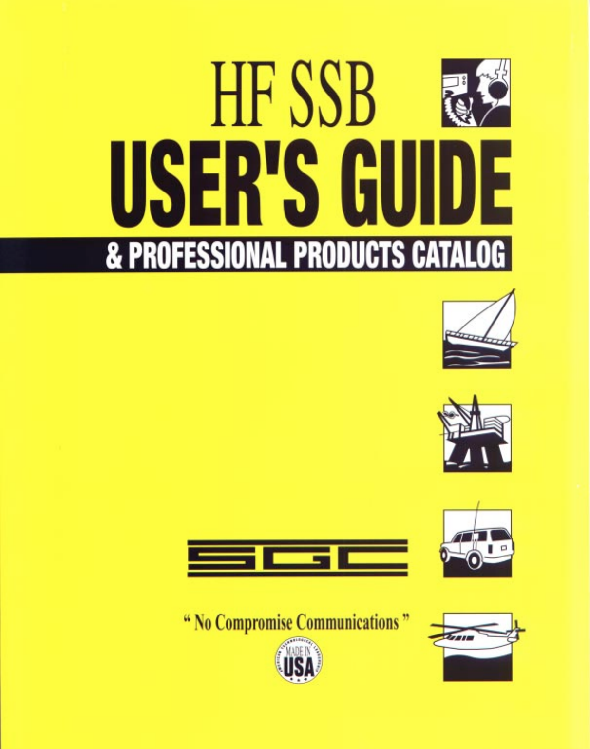
The pieces that fit together to form an AM broadcast signal are quite important. Although AM signals were
transmitted almost exclusively for
decades, it was discovered that
the AM signal could be dissected.
The first amateur radio operators
to experiment with these
processes often used both
sidebands without the carrier.
This is known as double sideband
(DSB). DSB was typically used in the earlier operations because it was much easier to strip out just the carrier than
to strip out the carrier and one of the sidebands. Several years later (and still true today), it was much more common
in the amateur bands to merely transmit using one of the sidebands, which is known as single sideband (SSB).
Single sideband transmissions can either consist of just the lower sideband (LSB) or the upper sideband (USB).
If you listen to an SSB signal on an AM modulation receiver, the voices are altered and sound a lot like cartoon
ducks. As a result, you must have a special SSB receiver to listen to these transmissions. Although this was often
difficult for the amateur radio operators of the 1950's, it is no longer a problem with today's modern SSB
transceivers, such as the SG-2000.
You might wonder why SSB modulation is used for some applications and AM is used for broadcasting. It is a
necessity for broadcasters to have excellent fidelity when transmitting music; otherwise, the typical radio listener
will tune to another station. In order to achieve excellent fidelity when transmitting music, both sidebands and the
carrier are necessary. To produce this AM signal, the transmitter is, in effect, working as three transmitters: one to
produce a strong carrier for each of the sidebands, an upper sideband, and a lower sideband. The result is that
approximately half of the transmitter power is "wasted" on a blank carrier and the rest of the power is divided
between the two sidebands. As a result, the actual audio output from a 600-watt AM transmitter (300 watts of
carrier + 150 watts on each sideband) would be the same as the SG-2000 150-watt SSB transmitter.
Let's run some numbers: Suppose you have a typical 5-kW broadcast transmitter. You will only be able to
impress 2.5 kW of audio power on that signal. This means that each of the two sidebands will have only
1.25 kW of power.
SSB'S HIGH EFFICIENCY
Page 12
10
The SGC Building, 13737 S.E. 26th St. Bellevue, Washington 98005 USA
P.O. Box 3526, 98009 Tel: (425) 746-6310 Fax: (425) 746-6384
© 1997 SGC Inc.
This is the key to highly effective communications using single sideband. A single
sideband signal removes the carrier and one sideband and concentrates all of its energy in
one sideband. Thus, a 1-kW SSB signal will "talk" as far as a
4-kW conventional AM or FM transmitter. It is why long
distances can be covered effectively with SSB.
Single sideband's benefit is not only evident on transmission. The reverse happens
on receive. When you work out the math, the efficiency with an SSB signal is 16 times
greater than with a conventional AM signal.
HF (high frequency) is synonymous with the more familiar term, shortwave. The only difference is that HF is
typically used when discussing two-way and point-to-point communications. Shortwave is typically used when
referring to broadcast stations in the same range. In amateur radio, both terms are frequently used.
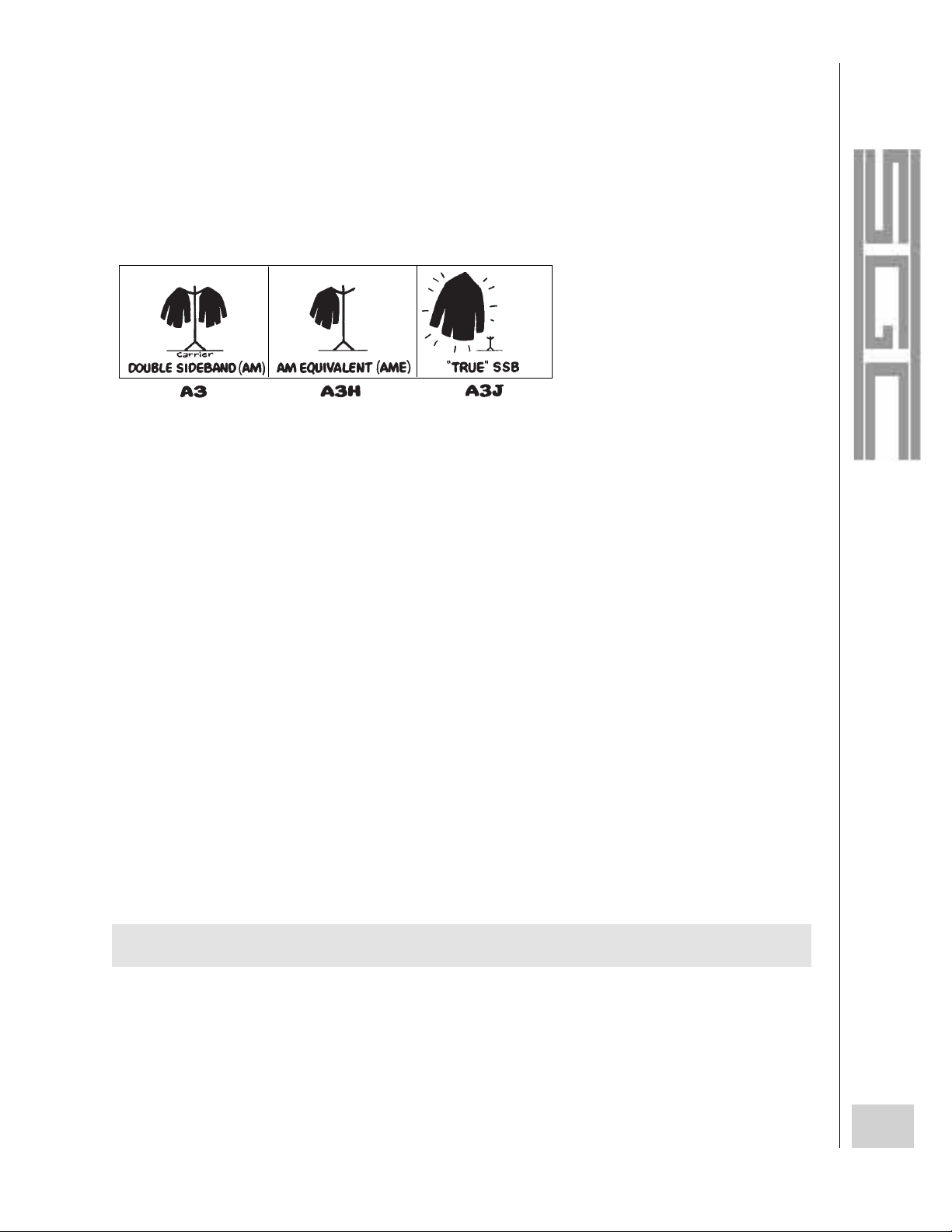
The HF band extends from 1700 to 30,000 kHz (1.7 to 30 MHz). To give some perspective to these numbers,
the AM broadcast band runs from 540 to 1700 kHz, the Citizen's Band (CB) runs from 26,960 to 27,230 kHz
(within the HF band), and television channel 2 is on 54,000 kHz. Each of these sample frequencies has different
characteristics, and it is vitally important to learn this information so that you can
effectively use the HF spectrum.
When talking about HF, most people list the frequencies in either kHz (kilohertz) or
MHz (megahertz). This is a matter of convenience only. The base rate for frequency is the
hertz (Hz), named after Heinrich Hertz, an important "father of radio." One kHz equals
1000 Hz and one MHz equals 1,000 kHz.
The Hz divisions of the radio spectrum aren't arbitrarily chosen hashmarks to divide your radio dial into usable
little pieces. Instead, the divisions relate directly to the frequency. Signals such as light, radio, and sound are all
waves. These waves travel through the air in a manner that is somewhat similar to waves in a pond. Each radio wave
has a peak and a valley. The length of each radio wave is (not surprisingly) known as the wavelength. Radio waves
The HF high
frequency band
extends from
1700 to
30,000 kHz
(1.7 to 30 MHz).
.5
1.61.82 3 4 6 8 12 16 22 56 88 108 156 176
BROADCAST LORAN
COASTAL COM-
MUNICATIONS
HIGH SEAS CHANNELS =
TV 2-6 FM
VHF
MARINETV7-13
FREQUENCY (MHZ)
HF VHF
30
CB
AMATEUR =
A single-sideband
signal removes the
carrier and one
sideband and
concentrates all of it's
energy in the remaining
sideband.
SSB Power! The
actual audio output
of a 150-watt SSB
transmitter is the
same as a 600-watt
AM transmitter.
HF SIGNAL CHARACTERISTICS
Page 13

11
The SGC Building, 13737 S.E. 26th St. Bellevue, Washington 98005 USA
P.O. Box 3526, 98009 Tel: (425) 746-6310 Fax: (425) 746-6384
© 1997 SGC Inc.
travel at the speed of light, so the longer each wave is, the fewer waves can arrive in one second. The number of
waves that arrive per second determines the frequency. Although the wavelength and the frequency are different
ways of saying the same thing, wavelengths for radio are rarely given. In the 1920's through the 1940's, the
wavelength was more frequently used than the frequency, however. This was probably the case because the
wavelength seemed like a more tangible measurement at the time. The wavelength of the radio signal is also
important because it determines the length of the antenna that you will need for receiving and especially for
transmitting. Antennas are covered later in this user guide.
Because of the signal characteristics on the AM and FM broadcast bands, combined with the less effective
internal antennas, radio signals are often thought of as being used for primarily local reception (100 miles or so).
However, with two-way communications in the HF band, you are not listening for entertainment to the strongest
station that you can find. You are attempting to communicate with a particular station under what could be lifethreatening circumstances.
In the 1910's and 1920's, it was thought by most radio enthusiasts that the "wavelengths above 180 meters"
were useless. In effect, these people believed that the frequencies above the top of today's AM broadcast band were
unusable. Little did they know that the opposite was true for communications over medium to long distances. The
reason that these pioneers were misled was because they didn't yet understand the methods by which radio waves
travel.
These methods are known as propagation, but they can be simplified to provide a basic understanding of the
subject. When you listen to a local AM broadcast station, you are receiving the ground wave signal. The ground
wave travels along the ground for often a hundred miles or so from the transmitter location. The low frequencies,
such as those in the AM broadcast band and lower, produce very large ground-wave patterns. The ground waves are
very important because they produce solid, virtually fade-free reception.
The other major method by which radio signals reach your receiver are the sky waves .
Sky waves travel toward the sky, rather than hang out on the ground. You would not be able
to hear the sky-wave signals, except for the ionosphere. The ionosphere is many miles
above the earth, where the air is "thin"containing few molecules. Here, the ionosphere is
bombarded by x-rays, ultraviolet rays, and other forms of high-frequency radiation. The
energy from the sun ionizes this layer by stripping electrons from the atoms.
When a sky-wave signal reaches the ionosphere, it will either pass through it or the layer will refract the signal
and bend it back to earth. The signal can be heard in the area where the signal reaches the earth, but depending on
a number of variables, there might be an area where no signal from that particular transmitter is audible between
the ground wave and where the sky wave landed. This area is the skip zone. After the sky-wave signal bounces on
the earth, it will return toward the sky again. Again, the signal will be refracted by the ionosphere and return to
the earth.
"Skywaves" travel
immense distances
by multiple
"bounces" off the
ionosphere.
Page 14
12
The SGC Building, 13737 S.E. 26th St. Bellevue, Washington 98005 USA
P.O. Box 3526, 98009 Tel: (425) 746-6310 Fax: (425) 746-6384
© 1997 SGC Inc.
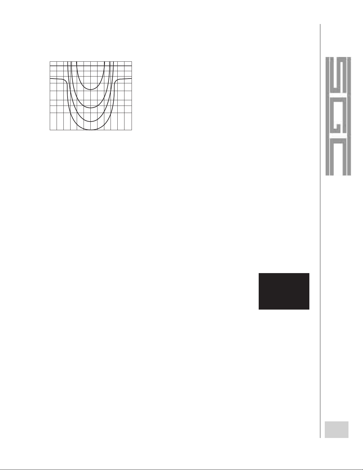
If the HF signals all bent and bounced off the ionosphere with no
losses in signal strength, HF stations around the world would be heard
across the earth with perfect signals (something like if a "super ball" was
sent bouncing in a frictionless room). Whenever radio signals are
refracted by the ionosphere or bounce from the earth, some of the energy
is changed into heat. This is known as absorption. As a result, the signal at
the first skip is stronger than the signal at the second skip, and so on. After
several skips, typical HF signals will dissipate.
The skip and ground waves can be remarkably close together. It is not unusual for one station to receive a
booming signal that nearly pegs the meter of a receiver. At the same time, a nearby station cannot hear a trace of the
sending station even though using a better receiver with a better antenna. The first station was receiving either the
ground wave or the first skip and the other station was located somewhere between these two.
If the HF users only had skip to contend with, the theories and uses of the HF spectrum
would be simple. But several other factors also come into play. The critical angle of radiation
is the steepest angle at which a radio signal can be refracted by the ionosphere. The critical
angle depends on the frequency that is being used, the time of year, the time of day, etc.
Sometimes a signal that shoots straight up from the antenna will be refracted by the
ionosphere. In this case, the critical angle would be 0 degrees. In another case, the signal
might slice through the ionosphere and continue into space. From this signal, you would not be able to determine
the critical angle; you would only know that the sky-wave signal was above the critical angle.
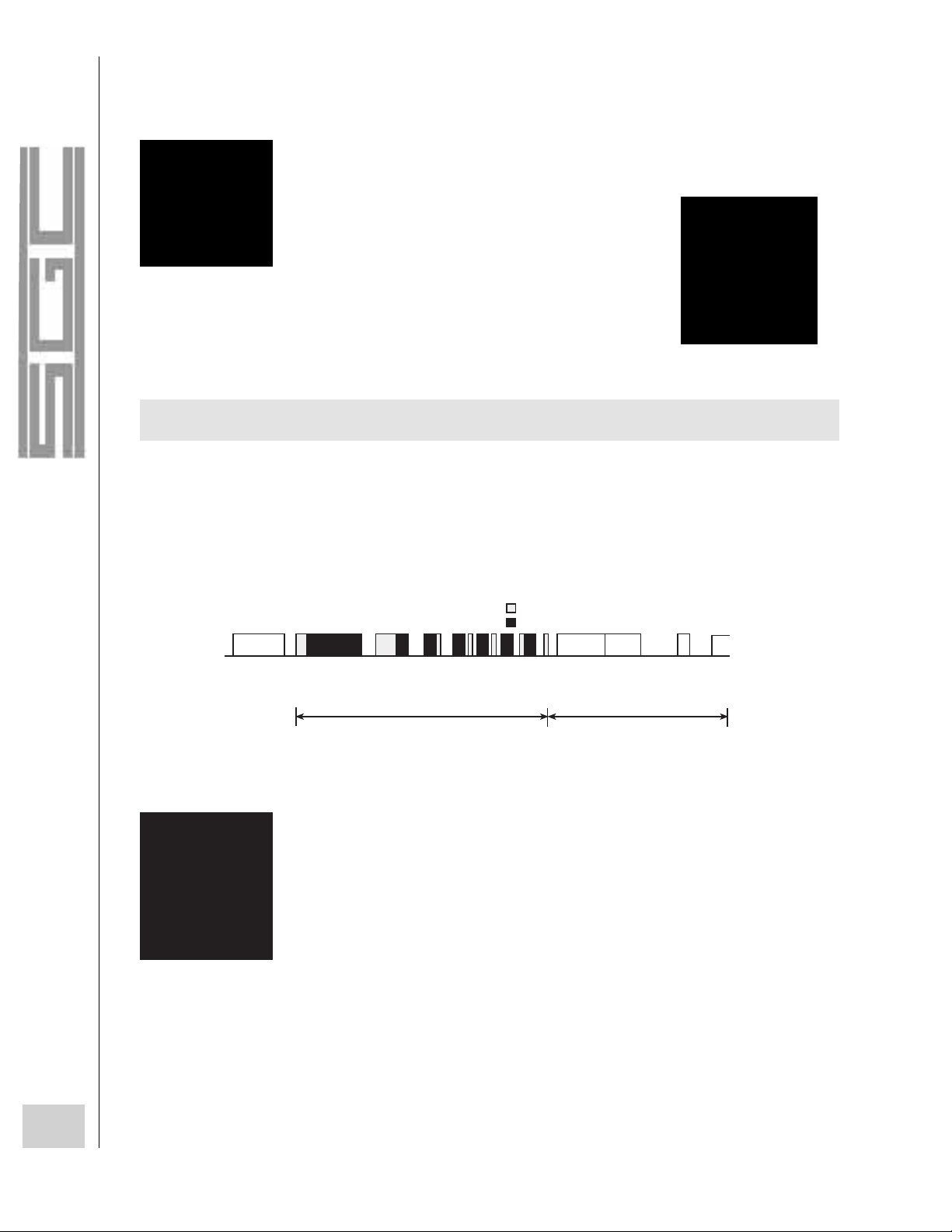
Aside from the critical angle, the frequency used can also affect whether the signal will be passed through or
refracted by the ionosphere. When a signal penetrates through the ionosphere without
being refracted, the signal is said to operate above the Maximum Usable Frequency (MUF)
. The MUF is not a set frequency; it varies greatly, depending on the time of day and the
part of the world that you are attempting to contact. Nearly the opposite of the MUF is the
lowest usable frequency (LUF). However, the LUF has nothing to do with whether or not
PROPAGATION
The Critical Angle of
Radiation is the
steepest angle at
which a radio signal
can be refracted by
the ionosphere.
NATURAL CYCLES THAT AFFECT PROPAGATION
1
0
0
0
m
ile
s
4
0
0
0
m
i
l
e
s
A
A
B
B
DURING THE DAY A 12 MH
Z SIGNAL (A) WOULD
PROPAGATE OUT TO 1,000 MILES, WHILE AT THE
SAME TIME, A 17 MHZ SIGNAL (B) COULD REACH
4,000 MILES OR MORE BECAUSE OF THE
INCREASED REFLECTION ANGLE.
The Maximum U
sable
Frequency (MUF)
is lowest at night and
highest during
the day.
Page 15
13
The SGC Building, 13737 S.E. 26th St. Bellevue, Washington 98005 USA
P.O. Box 3526, 98009 Tel: (425) 746-6310 Fax: (425) 746-6384
© 1997 SGC Inc.
the signal will be refracted by the ionosphere; instead, it is the
lowest frequency that you can use to reach a particular region
(using a base standard amount of power).
In the daylight hours, the MUF is highest and in night hours,
it is lower. There is also some seasonality, too. In the winter, with
longer hours of darkness, the MUF is generally lower than the
summer when the MUF is higher. Likewise, during the hours of
darkness, when the ionosphere is less ionized, the LUF is lower,
and during the daylight hours, it is much higher. The MUF and the
LUF provide the boundaries between which you should operate
the transceiver in order to make your contacts.
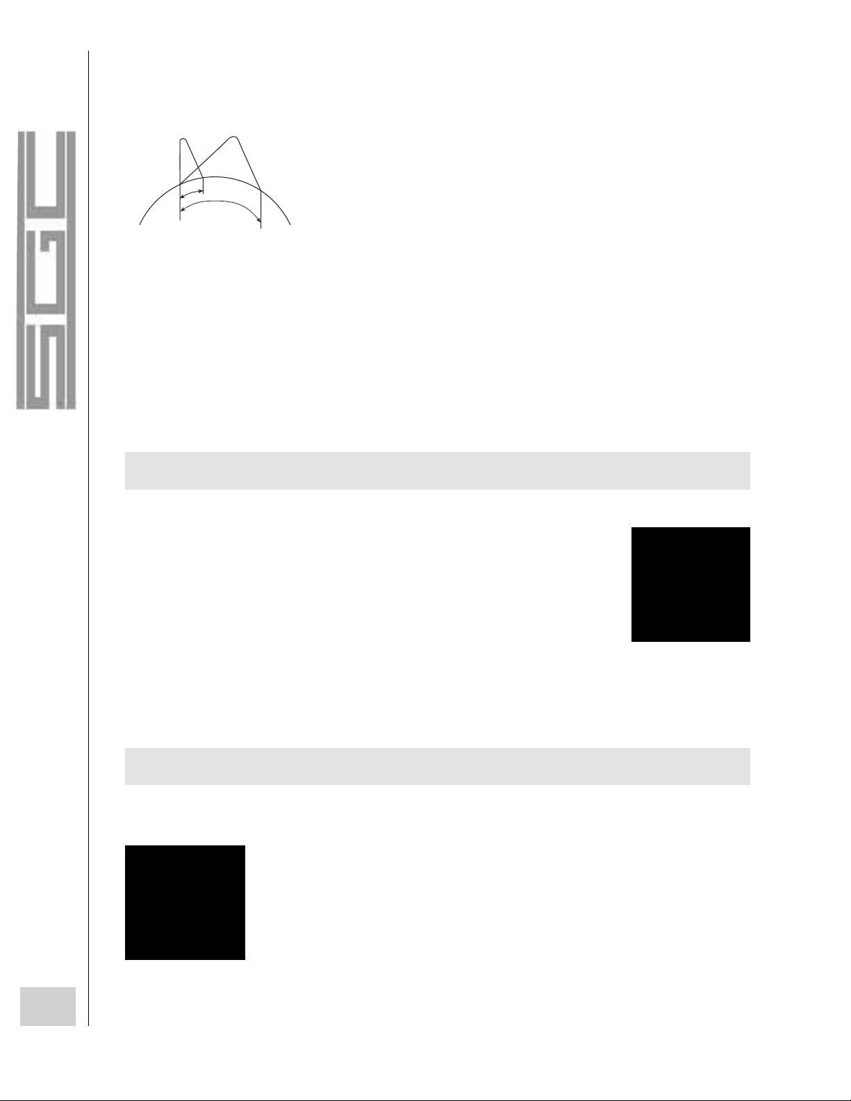
As mentioned in the previous paragraphs, propagation is affected by cyclical environmental conditions. The
shortest of these conditions is the day/night cycle. In general, the transmitting and receiving conditions are by far the
best in the nighttime hours. During the daytime, the MUF and LUF both rise and in order to talk across great
distances, less reliable (because of the very long skip) higher frequencies must be used.
The next environmental cycle that affects propagation is the season of the year. The winter/summer cycles are
somewhat like the day/night cycles, except to a lesser extent. In general, the MUF and LUF will both be higher in
the summer and lower in the winter. Also, the noise from thunder storms and other natural phenomena are much
higher during the summer. In fact, except for local transmissions, communications in the 1700 to 3000 kHz range
during the summertime are of limited regular use.
The longest environmental cycle that affects propagation is the sunspot cycle. Before
the age of radio, it was noticed that the number of solar storms (sun spots) varies from year
to year. Also, the number of sunspots per year was not entirely random. The number of solar
storms during a good propagational month is above 150 and the number during a weak
month is often less than 30. After many years of studying these results, it was determined
that the sunspot cycle reaches its peak approximately every 11 years and that these cycles have a great impact on
radio propagation. Between these peaks are several years with very low sunspot activity. During years with high
sunspot activity, the MUF dramatically increases and long-distance communications across much of the HF band is
possible. During the peak of the last sunspot cycle, in 1989, the MUF was often above 30 MHz! When the cycle is
at its low point, the MUF decreases and much less of the HF band is usable for long-range communications.
Generally, the frequencies above 10000 kHz dramatically improve during the peak years of the sunspot cycle, and
the frequencies below 10000 kHz are much less affected.
17 MHZ
12 MHZ
8 MHZ
4 MHZ
0 2 4 6 8 10 12 14
16 182022 24
1KL
1.5K
2K
3K
4K
5K
6K
7K
LOCAL TIME
MAXIMUM RANGE FOR VARIOUS MARINE BANDS AS A FUNCTIO
OF TIME OF DAY
During years of high
sunspot activity,
the MUF
dramatically
Page 16
14
The SGC Building, 13737 S.E. 26th St. Bellevue, Washington 98005 USA
P.O. Box 3526, 98009 Tel: (425) 746-6310 Fax: (425) 746-6384
© 1997 SGC Inc.
Although the long distances that HF radio signals can be received is amazing, in comparison to the other radio
bands, several types of distance-related interference can ruin reception or make listening
unpleasant. The most widespread type of interference fits under the broad heading of noise.
Noise consists of natural and man-made noise. Natural noise is produced by everything
from thunder storms to planets (hence, radio telescopes). Thunder storms are the worst
because they cause very loud crashes; because of the long distances that shortwave signals
travel, the noise produced by thunderstorms is also likely to travel hundreds of miles (or
further). Even if the weather is clear (you should never operate HF equipment during a local thunderstorm!), a
distant thunderstorm could ruin your reception of a weak station that would otherwise be audible at your location.
Man-made interference can arrive from a vast variety of sources. If nothing else, at least most man-made
interference is limited in its range; most is limited to the building that the equipment is located in or to a severalblock surrounding area. One of the worst causes of man-made interference is caused by fluorescent lights, which
create a medium-strength buzz across the HF range, although it is often at its worst on the lower frequencies. In fact,
fluorescent lights near an antenna can drown a normally usable signal. If your radio is located near computers, it
will probably receive a light buzz across the bands and much stronger "bleeps." These interference problems are
covered further in this user guide.
Adjacent-channel interference is a special type of man-made interference where a station from a nearby
frequency is "washing over" or "splattering across" another. A somewhat similar type of interference is co-channel
interference, where the interfering station is on the same frequency. A good example of co-channel interference is
the 1400 to 1500 kHz "graveyard" region of the AM broadcast band in the evening hours, where dozens of signals
are all "fighting" to be heard.
Other types of HF interference cause signal distortion from the propagational effects. One of the most
interesting effects is polar echo, which occurs when one component of a radio signal takes an East-West path and
another arrives over one of the poles of the Earth. Most every morning, one can tune into one of the BBC broadcast
transmitters and hear the effect of polar echo. Because the signals take different paths, they arrive at different times,
creating an echo on the audio signal. During the lightest effects, the voices sound a bit "boomy;" at worst, the delay
is so long that the programming is difficult to understand. A related phenomena is polar flutter, where the signal
passes over one of the poles and very quickly fades up and down in strength, creating a
"fluttery" sound.
Fading is the most common and damaging form of propagational interference. The two
most common types of fading are selective fading and multipath fading. With selective
HF INTERFERENCE
Fading is the most
common form of
propagational
interference.
Noise consists of
natural (e.g. thunder)
and man-made (e.g.
fluorescent lighting)
interference.
Page 17

15
The SGC Building, 13737 S.E. 26th St. Bellevue, Washington 98005 USA
P.O. Box 3526, 98009 Tel: (425) 746-6310 Fax: (425) 746-6384
© 1997 SGC Inc.
fading, the ionosphere changes orientation quickly and the reception is altered (somewhat like a ripple passing
through the signal). Because of these effects, it is best to use the narrowest mode possible, if selective fading is a
problem. As a result, FM and AM signals are especially prone to selective fading, SSB is slightly affected, and the
CW mode is almost free from selective fading. The other type, multipath fading, occurs when signals take different
paths to arrive at the same location. Multipath fading is a variation of polar echo; instead of the signals creating an
echo effect, the phase of the signals are altered as they as refracted by the atmosphere. As a result, the received
signal fades in and out.
The last major propagational effect does not actually cause interference to a signal; it absorbs it. Although sun
spots are beneficial to propagation as a whole, solar flares destroy communications. During a solar storm,
communications across a wide frequency range can suddenly be cut off. Many listeners have thought that their
receivers either weren't working or that the exterior antenna had come down because virtually no signals were
audible. Instead, they had turned on their radios during a major solar flare. On the other hand, other listeners had
thought they were listening during a solar flare, but actually didn't have their antenna connected or they had tuned
their radio above the MUF or below the LUF.
As covered in the preceding section, signals take various routes to travel to a receiver from the transmitter. The
problems that can result from signal paths include polar flutter and echo, and multipath fading.
The signal path is also important when attempting to contact or receive signals from a particular area. When
you receive a signal, you can typically assume that it took the shortest path to reach you (i.e. you could connect the
points between the transmitting and receiving locations with a line on a globe). This is known as short-path
reception. Exceptions to this rule occur when two or more different paths are nearly the same distance (such as the
BBC example of polar flutter, where the north-south path isn't much longer than the east-west path).
The other major signal path is the long path. The long-path radio signal travels the opposite direction from the
short-path signal. For example, the long-path signal from the BBC transmitter (mentioned earlier) would be east:
across Europe, Asia, the Pacific Ocean, most of North America, and finally it would arrive in Pennsylvania. As you
can imagine, the signals received via long path are often very weak--especially if the long path was very long and
the frequency is low. On the other hand, if the station is on the other side of the world and there is little difference
between the long path and the short path, you could be receiving either or both. This case occurred recently to a
listener on the east coast of the USA who was listening to a small, private broadcast station from New Zealand - 12
time zones away. At the same time he was listening to it, it was also being heard throughout North America and in
Germany. Because the signals were generally a bit better in the West and Midwest, we can assume that he heard the
Pacific Ocean-to-Western North America route, rather than the one that passed through Asia and Europe.
SIGNAL PATHS
Page 18
16
The SGC Building, 13737 S.E. 26th St. Bellevue, Washington 98005 USA
P.O. Box 3526, 98009 Tel: (425) 746-6310 Fax: (425) 746-6384
© 1997 SGC Inc.
One of the most intriguing propagational anomalies is the effect of the grey line on HF radio transmissions. The
grey line region is the part of the world that is neither in darkness nor in daylight. Because two grey-line stripes are
constantly moving around the earth, the propagational alterations are very brief (usually only about an hour or so in
length). Many amateurs and hard core radio listeners actively scour the bands at sunrise or
sunset. The ionosphere is highly efficient at these times, so listeners can often pull in some
amazing catches. Grey-line propagation is probably of far less interest to those who use the
radio bands in conjunction with their occupation. If you are one of these users, chances are
that grey-line propagation will be either a curiosity or a nuisance, as more stations that could
cause interference to your signal become audible.
Because HF communications are capable of covering such large distances and because they are so complex,
you must plan out your system and your operating techniques in advance. Of course,
in order to participate in two-way communications in the HF bands, you must have a
receiver, a transmitter (these two are usually combined to form a transceiver), and an
antenna. The type of antenna that you choose, the manner in which you construct it,
and the ground system that it connects with are all key factors in the success of your
operations. HF transceivers vary greatly in type, power, construction, frequency ranges, operating modes, features,
etc., so you must be sure that you purchase a model that best suits your requirements. SGC transceivers and
antennas are covered further in this user guide.
Depending on your location, the frequencies that you are allocated to use, and the
distance from your contacts, the amount of power output that you will require will vary. In
any case, only use as much power as necessary to make the contact. If you use more power,
many more people will listen to your transmissions and (especially for amateur radio
operators) your signal could cause interference in the over-crowded amateur bands. As a
result, some transceivers, including some of those from SGC, allow you to continuously
decrease the power output.
In order to effectively communicate on the HF bands, you will probably need to spend some time "studying"
the propagational effects first hand. The best way to do this is to purchase or borrow an inexpensive generalcoverage shortwave receiver or a transceiver, if you don't already own one. Install an antenna and listen across the
shortwave bands. The shortwave broadcast stations are fun and interesting to listen to, but most use tremendous
transmitter powers--often as great as 500,000 watts output! As a result, you cannot really assess the range of your
signal (or someone else's) just by listening to these broadcasters.
The Grey Line region is
the part of Earth that
is neither in darkness
or daylight-the
ionosphere is highly
efficient at these
times.
OPERATING NECESSITIES
For privacy, and to
avoid conflict with
other signals, only
use as much power
as necessary to
make the contact.
Page 19
17
The SGC Building, 13737 S.E. 26th St. Bellevue, Washington 98005 USA
P.O. Box 3526, 98009 Tel: (425) 746-6310 Fax: (425) 746-6384
© 1997 SGC Inc.
The best indications of the bands, the distance of skip, and the distances that you can cover are by listening to
stations in the bands (the general frequency areas) that you will be working or by listening to nearby amateur radio
bands. Some beacon stations operate in the amateur radio bands to provide radio enthusiasts
with an as-it-happens guide to propagation conditions. Beacon stations usually transmit
their call sign over and over in Morse code, according to a particular schedule (often 24
hours per day). If you listen to these beacons, know the power and locations, you can use
them as an accurate yardstick to measure the conditions. If you are an amateur radio operator, you can check into
several nets (networks) and ask those involved for an outlook on the present and upcoming propagation conditions.
Listening is one the most important aspects of having successful operations. It might not make a difference if
you are using a 30-watt transceiver to communicate with someone a few miles away, but radio experience and good
listening skills are a must for long-distance communications. Because of the static, fading, and interference that
sometimes plagues the HF frequencies over long distances, you must be able to mentally "filter out" this noise.
Experienced "ears" are able to log relatively low-powered AM broadcast outlets while the untrained listener
wouldn't hear the broadcaster at all. It will sound like static to them!
In addition to gaining experience by listening to the HF bands, it is very important to
keep up to date with various sources of outside information. The outside sources can be
either in broadcast or written form. Some of the best amateur radio publications are available
from the Amateur Radio Relay League (ARRL). The ARRL sells a number of excellent
books of various aspects of the amateur radio hobby, and most of these books relate quite
well to other HF radio services. In addition, the ARRL also produces one of the best amateur
radio magazines, QST. For more information on the products and services available from the ARRL, contact:
ARRL, 225 Main St., Newington, CT 06111, USA.
Another publisher of technical books is TAB/McGraw-Hill. In addition to selling a number of beginner-,
intermediate-, and advanced-level books on electronics, shortwave, and computers, the company also offers one of
the best antenna books available. Joe Carr's Practical Antenna Handbook (2nd Edition), covers most every practical
antenna design with a down-to-earth approach. For a catalog, write to: TAB/McGraw-Hill, Blue Ridge Summit, PA
17214-0850, USA or call (800) 822-8158.
Two excellent annual guides to HF/shortwave broadcast listening are available. The World Radio TV
Handbook features hundreds of pages of frequency listings, addresses, transmitter sites for AM, HF/shortwave, and
television broadcast stations around the world. For more information, write to: WRTH, BPI Communications, 1515
Use beacon
stations to
determine
broadcast
INFORMATION SOURCES
Some of the best
amateur radio
publications are
available from the
Amateur Radio
Relay League
Page 20

18
The SGC Building, 13737 S.E. 26th St. Bellevue, Washington 98005 USA
P.O. Box 3526, 98009 Tel: (425) 746-6310 Fax: (425) 746-6384
© 1997 SGC Inc.
Broadway, New York, NY 10036, USA. The Passport to World Band Radio covers the same general topic as the
WRTH, but it features less raw information and more interpretations of information and trends in international
broadcasting. For more information, write to: Passport to World Band Radio, IBS, Box 300, Penn's Park, PA 18943,
USA. Whether or not you are interested in HF/shortwave broadcasting, either of these books are invaluable if you
need to discover what Latin American stations are fading into the 6200 kHz area marine frequencies or what
African broadcasters are booming into the 40-meter amateur band.
Aside from QST, several other informative amateur radio magazines are available. CQ is now in its 50th
anniversary and it is available on newsstands or from: CQ, 76 North Broadway, Hicksville, NY 11801, USA. 73
Amateur Radio Today, 70 Route 202 North, Peterborough, NH 03458, USA covers the amateur radio hobby, but
seems to go more for the homebrewing/kit-building angle. All three of the major amateur radio magazines cover
propagation from month to month, and they feature practical information about how to make the most of the varying
HF conditions. Also, they all have interesting tips, modifications, and antenna projects to make your operating
easier and more effective.
Several other magazines might be of interest to those who are interested in HF broadcasts or to government,
military, or marine operators. Monitoring Times and Popular Communications magazines cover a variety of radiolistening topics and columns, from longwave through microwave communications. For more information, write to:
Monitoring Times, 140 Dog Branch Rd, Brasstown, NC 28902, USA (800) 438-8155 and Popular Communications,
76 North Broadway, Hicksville, NY 11801, USA.
For more up-to-date information on the propagational conditions, you can listen to radio stations WWV and
WWVH, which are the two time and frequency standard stations for the United States. Being a time station means
both of these stations only broadcast time pips and the tone at the top the minute, along with announcements as
such. WWV and WWVH are set to an atomic clock, which ensures that they are exactly on time. Being a frequency
standard means that the stations are exactly on frequency, and they can be used to calibrate transceivers or frequency
counters. WWV (from Ft. Collins, Colorado) and WWVH (from Kauai, Hawaii) both broadcast on 2500, 5000,
10000, and 15000 kHz. WWV also broadcasts on 20000 kHz. The two broadcasts are exactly the same, except that
WWV features a male announcer for the time checks and WWVH airs a female announcer.
Every hour (at 18 minutes past the hour on WWV and 45 minutes past the hour on WWVH), the stations
broadcast propagation reports. These reports are updated daily between 2100 and 2200 UTC and they are the most
up-to-date information that is available (short of kidnapping an ionospheric scientist).
WWV and WWVH broadcast information about three different propagational factors: the A index, the K index,
and the solar flux. The A index and K index are related values that reflect the amount of geomagnetic activity in the
ionosphere. This explanation sounds complicated and it is. What is important to know is that the lower the numbers
are, the quieter the conditions are; the higher the number are, the more stormy the ionospheric conditions are. If the
A and K indexes are very low (0-10 for the A and 0-3 for the K), the propagation should be better. The last of the
Page 21

announced WWV/WWVH propagation conditions is the solar flux. The solar flux is directly proportional to the
sunspot number, so as covered earlier, the higher solar flux number (which would occur near the peak of the sunspot
cycle) makes for much better propagation on the frequencies above 10000 kHz.
Over the HF spectrum, a number of different operating modes are used for two-way communications. The
operating mode is a format of the data and the manner in which it is transmitted. For example, although SSB and
AM (covered earlier) are both in the voice format, they are transmitted in different manners. The following modes
are used frequently across the HF spectrum.
CW (Continuous Wave) CW is a binary code that consists of "dits" and "dahs" as a transmitter is
being keyed on and off. Although a number of different codes have been used since the days of the telegraph, the
only one that is widely used is Morse code. All amateur radio operators who use the HF bands are required to send
and receive Morse code at at least five words per minute (wpm). CW might appear to be outmoded now that today's
computers can send and receive many types of digital communications reliably. However, the CW signal is very
efficient because only the pattern of the signal (not the audio on the signal) needs to be understood and because the
signal can be very narrow. As a result, CW is the most reliable form of communications for human operators.
AM (Amplitude Modulation) As was covered earlier, the AM mode consists of a base carrier, a
modulated upper sideband, and a modulated lower sideband. However, some of the newer transceivers that have this
mode use the SSB signal with a carrier inserted to produce a faux AM signal. Although true AM is the favorite
mode of AM band and shortwave broadcasters, it is rarely used elsewhere because it is inefficient and because it
requires a large amount of space in the already-crowded amateur bands. For the most part, the only AM two-way
stations currently on the air are nostalgic amateurs who love the broadcast-quality audio from this mode.
19
The SGC Building, 13737 S.E. 26th St. Bellevue, Washington 98005 USA
P.O. Box 3526, 98009 Tel: (425) 746-6310 Fax: (425) 746-6384
© 1997 SGC Inc.
MORSE CODE
OPERATING MODES
VOICE
Page 22

20
The SGC Building, 13737 S.E. 26th St. Bellevue, Washington 98005 USA
P.O. Box 3526, 98009 Tel: (425) 746-6310 Fax: (425) 746-6384
© 1997 SGC Inc.
As was covered earlier, SSB is one half of the voice component of the standard AM signal. The SSB mode
is nearly always used for two-way communications across the HF spectrum. SSB is so popular because the mode
is much more efficient than any other voice mode and because the signals are narrower, so it is rarely hampered
by fading.
RTTY (Radio Teletype) RTTY (often pronounced as "ritty") is one of the earliest forms of data
communications. In this system, printed data is transmitted via a high-speed machine, rather than hand-keyed, as is
the case with CW communications. Although CW is a form of data communications, it is copied by a human
operator. Nobody can copy RTTY by ear. RTTY is a completely different world of communications from the voice
modes. To try to thoroughly cover this topic here would be somewhat like trying to cover every aspect of DOS and
Windows in one introductory book on computers. As a result, the information in the following paragraphs is only
intended to provide some basic information and to whet your interest in this branch of the technology.
In order to send and receive RTTY, you must have other equipment in addition to the standard HF
transceiver/antenna combination. Today, the most common arrangement would be to interface a personal computer
with your transceiver and purchase the appropriate demodulating/modulating software or a computer interface.
If no computer is available, then you are stuck with purchasing a modulator/demodulator (modem), a monitor,
and a printer.
The three major branches of RTTY communications are Baudot, AMTOR, and ASCII. The characters in
Baudot code are formed by blocks of five-digit binary codes and an initial arrow. There are "old-timer"amateur
radio/MARS friends who who have Baudot RTTY units from the mid-century. These hulking blocks of steel are true
mechanical wonders--something like a giant typewriter and printer combination in a desk-sized case full of gears.
The catch with Baudot code is that it directly intermeshes with these mechanical printers and it is prone to
interference--fades, static, and man-made interference, which cause errors in the received messages.
AMTOR is (simplified) RTTY Baudot code that has been modified to add various error-detection and
correction enhancements. The AMTOR system corrects data by sending it in time-delayed chunks. The transceivers
are connected to a "smart box"--a computer modulator/demodulator. Then, the transmitting station will send a block
of data and the receiving station will receive it and transmit a signal back to verify that it received the signal. If the
signals from the transmitting station are not received properly, then the receiving station will transmit a signal for
the other station to repeat that block of text. This process will continue until the entire message is sent. Technically,
SSB (SINGLE SIDEBAND)
DATA
Page 23

this transmit/receive/verify process is called handshaking.
SITOR is a version of AMTOR that is used especially for marine and weather information. As a result,
SITOR is mostly important for marine operators. Some Coast Guard and Marine Coast stations operate in the
commercial marine bands. Otherwise, some press frequencies in the 8 and 12 MHz bands are still audible. Just
below the AM broadcast band on 518 kHz is a good bet for hearing U.S. Coast Guard information, which is
broadcast to ships at sea.
ASCII is a very familiar term to many people in the 1990's because of the popularity of computers. Nearly
every computer editing system uses ASCII or some derivative of ASCII. As a result, it makes sense that ASCII
would also be used to communicate data on the HF bands. Like Morse code and Baudot code, ASCII is a binary
code. However, it differs from Morse because it uses 0 and 1 in the code (instead of dots and dashes) and it differs
from Baudot code because it uses a seven-digit instead of a five-digit code.
When speaking of digital transmissions, whether RTTY radio transmissions, or computer/modem
transmissions, the baud rate is the speed by which the information is transferred. The baud rate is determined by the
bits of information (each electrical impulse) that flow through the system. Typical baud rates for computers are 300,
1200, 2400, 9600, 14,400, and 28,800 bps (bits per second). By the mid 1990's, most of the transmissions were in
the last three speeds. The baud rates for RTTY are generally much slower because of the lower quality for the
transmissions (static crashes, fades, adjacent-channel interference, etc.). Most RTTY baud rates are 100 bps or less.
One of the most interesting forms of data communications is packet radio. Packet radio is so named because
information is broken up into small packets and sent hither through the radio waves. Unlike the typical forms of data
communications (where the send and receive process is very noticeable), packet radio is more like having a wireless
computer BBS. The packet messages can be stored and recalled at a later date, the communications are relatively
error-free, and the information can be sent to many interconnected stations.
The data transmissions are interesting and useful because they can be used essentially like E-Mail. RTTY
doesn't have the advantages that it once had, now that the Internet has become "the information highway." Still,
RTTY and packet radio are free to use if you are licensed to do so, and it's fun!
The most common form of video transmission is television. In addition to the broadcasts in the typical
television band, special slow-scan television (SSTV) is also broadcast in the amateur radio bands. SSTV is different
from regular TV in that the commercial TV broadcasts are actually Fast-Scan TV. SSTV is different from FSTV
because the scan rate is much slower. That means that the screen is updated at a much slower pace than regular TV.
As a result, SSTV is much more useful to transmit still images than moving images. Like the other forms of amateur
21
The SGC Building, 13737 S.E. 26th St. Bellevue, Washington 98005 USA
P.O. Box 3526, 98009 Tel: (425) 746-6310 Fax: (425) 746-6384
© 1997 SGC Inc.
VIDEO
Page 24

22
The SGC Building, 13737 S.E. 26th St. Bellevue, Washington 98005 USA
P.O. Box 3526, 98009 Tel: (425) 746-6310 Fax: (425) 746-6384
© 1997 SGC Inc.
radio, only noncommercial, two-way communications can be transmitted, so don't expect to watch your favorite
show on the SSTV frequencies. In order to send and receive SSTV signals, you would need a TV or TV monitor, a
scan converter, and camera, in addition to an HF SSB transceiver.
One mode that is somewhat of a cross between a digital and a video mode is facsimile (fax). For most people,
faxes were born in the 1980's; however, radio faxing goes back to the late 1920's, when the mode first experiments
were taking place. Several years later, fax services, such as a special radio fax station that only transmitted the
New York Times, were active. Like the standard telefax machines, radio fax sends the data line by line until
the picture is complete. Some amateur radio companies are manufacturing relatively inexpensive modem units
specifically to interface with computers and receivers so that you can send and receive faxes via the
HF frequencies.
For more information on data and video communications, check out the annual ARRL Handbook for Radio
Amateurs by the staff of the American Radio Relay League, Your Gateway to Packet Radio by Stan Horzepa, The
RTTY Listener by Fred Osterman, The Guide to World RTTY Stations and The Guide to Facsimile Stations by
Joerg Kingenfuss, The Weather Satellite Handbook by Dr. Ralph Taggart,The Packet Radio Handbook (2nd
Edition) by Jon Mayo, and The Amateur Television Workbook by M. Stone.
There are many situations in remote areas developing countries where HF systems offer superior performance
at a lower cost than VHF and UHF communications systems. HF SSB communications is far more reliable-especially where mountainous terrain or distances over 14 miles are encountered.
The coverage of this manual is confined to the HF spectrum, but it is important to know about the other radio
bands. For example, as you go higher than about 30 MHz, the radio spectrum starts operating a lot more like light;
radio signals operate under the "line-of-sight" theory. Instead of being refracted by the ionosphere, as they do at the
lower frequencies, signals at the higher frequencies (typically 50 MHz and higher) cut right through the ionosphere
and into outer space. This is the same thing that happens when the MUF is low and the signals on the upper regions
of the HF spectrum cut through the ionosphere. Because no "skip" can be relied upon (unlike on the HF
frequencies), VHF and UHF signals typically do not travel long distances unless the towers are very high and very
high powers are used. Although the signals in the regions above 30 MHz can sometimes skip hundreds of miles, this
sort of propagation is very irregular and cannot be relied upon.
VHF/UHF COMMUNICATIONS
HF SSB vs. VHF/UHF RADIO COMMUNICATION SYSTEMS
Page 25
23
The SGC Building, 13737 S.E. 26th St. Bellevue, Washington 98005 USA
P.O. Box 3526, 98009 Tel: (425) 746-6310 Fax: (425) 746-6384
© 1997 SGC Inc.
"Skip" is a key to understanding HF radio: at most any time of day, you should be able to transmit a signal to a
given part of the world with a relatively small amount of power. Although these long-distance "skywave"
characteristics make up the bulk of HF operations, don't ignore the ground-wave function of HF for short-range
communications. The "perfect-signal" ground-wave range for HF frequencies depends on the season, the daily
propagation conditions, the frequency chosen and the time of day.
Although the moon has been used to achieve great distances under experimental conditions using "moon
bounce" VHF and UHF communications, the tracking requirements and the sophisticated equipment required render
this type of communications useless for regularly scheduled radio operations.
HF radio signals (2 to 30 MHz) can be received at distant locations using either ground-wave or sky-wave
signals. Ground-wave signals follow the contour of the ground in hilly regions for 1 to 50 miles, depending on
frequency. At distances greater than 50 miles to several thousand miles, sky-wave
signals, which bounce off the F2 layer of the ionosphere are involved.
Unlike HF signals, those in the VHF/UHF range do not follow the contour of the
ground. Once again, the "line-of-sight" theory comes into play. If you are using a VHF
or UHF communications system and are deep in a valley, your signal or that from the
repeater might be blocked by the terrain. Or if you were in a city, tall buildings or other
man-made objects could obstruct the signals. In cases such as these, your
communications equipment would be rendered useless until you once again were back in
the line-of-sight range of the receiving station.
COVERAGE
Ground Wave signals
follow the contour of
the Earth--in hilly
areas from 1 to
300 miles.
Sky Wave signals can
bounce several
thousand miles off
the ionosphere.
Page 26

24
The SGC Building, 13737 S.E. 26th St. Bellevue, Washington 98005 USA
P.O. Box 3526, 98009 Tel: (425) 746-6310 Fax: (425) 746-6384
© 1997 SGC Inc.
Because of the limited distance covered by VHF/UHF systems, most installations require some method of
relaying signals UHF/VHF signals to establish reliable communications at significant distance. Typically, radio
amateurs, commercial radio operators, and others, use a system of repeaters to relay these signals. A repeater is a
transmitter, receiver, and duplexer combination that are connected to an antenna on top of a tall tower.
The first step of repeater operation is to transmit a message via a handheld transceiver that looks something
like a cellular phone. The signal from the handheld is received by the receiving portion of the repeater. Then, the
output from the receiver is fed directly into the transmitter, which transmits the signal with more power and with a
taller antenna. The duplexer isolates the receiver and transmitter and allows one antenna to be effectively used for
both receiving and transmitting. Although it might appear that the repeater transmitter would be transmitting
continuously (whether or not anyone was being relayed), it's not; the strength of the input turns on ("keys") the
repeater's transmitter.
Repeater-type VHF/UHF operations are much more costly than comparable HF systems in many situations.
Repeaters require installation on the highest possible terrain, power source, tower(s), and a building to house
equipment. This high terrain can cause problems because if no such land is already owned, it must be purchased.
Then, a permanent building must be constructed to house the repeater and a power system (probably power lines or
a generator power system). In order to construct this system, land (for the repeater site) and a road might need to be
cleared. Depending on country, weather (such as high winds and extreme temperatures) can also force changes in
the system design.
Aside from the costs, one of the worst aspects of VHF/UHF repeater use is that the locations are vulnerable. In
the case of HF communications, the transceivers are taken to each site by the operators. The transceivers and
antennas can even be installed in a car or carried in a backpack unit. With a repeater, the portable units are handheld
or mounted in a a vehicle, but the repeater site, the most important, expensive, and powerful link in the system, is
abandoned and vulnerable to anyone who might want the equipment or the site. Therefore, consider the physical
security if you plan to use VHF/UHF repeaters.
You should allocate the same level of security to a critical repeater site as you would give to a critical central
telephone exchange or satellite ground station. Your communications are of crucial importance, and a UHF/VHF
system is only as strong as the weakest link.
REPEATERS REQUIRED ON VHF/UHF
Page 27

25
The SGC Building, 13737 S.E. 26th St. Bellevue, Washington 98005 USA
P.O. Box 3526, 98009 Tel: (425) 746-6310 Fax: (425) 746-6384
© 1997 SGC Inc.
HF single sideband technology has been a dependable system for more than 50 years in various international
communications services on frequencies allocated by the International Telecommunications Union(ITU) for
commercial telephone and data services and within individual countries, as permitted by treaty. SSB is the mode of
choice by leading military organizations and international airlines, which use HF SSB to keep in contact with units
on the move throughout the world.
A typical fixed HF SSB installation consists of a transceiver and an antenna, which could be a short vertical or
a 20 to 90 foot wire suspended from a tree or rooftop. Mobile installations use an efficient 9
foot whip antenna. No repeaters are required for communications that range from local to
intercontinental.
The range varies, depending on the frequency used. In the daytime, higher frequencies
are used for long-range communications. This is because the F2 layer (one of several major layers) of the
ionosphere, which reflects HF radio signals, lowers at night. This daily movement of the F2 layer is also why distant
stations can be heard at night on the AM broadcast band.
Single sideband technology requires a more sophisticated receiver to intercept signals than VHF/UHF systems,
which use simple FM signals. Although the SSB mode is somewhat common among amateur operators, it inherently
provides some security of communication. This is the "cartoon duck" sound (when listening on a typical shortwave
receiver) that was mentioned in the first section of this user guide. Also, several different types of scrambling
devices (such as the SG-1703 high-security scrambler) are available.
Repeater systems are prone to be misused unless some radio security feature is placed on its input. If others
learn of the repeater in the area and decide to use it for themselves, they only have to determine the input (receive)
frequency of the repeater and transmit a signal on that frequency. Then, their signal will be re-transmitted by the
repeater. Such communications could be used with harmless or malicious intentions.
To avoid these problems, repeaters sometimes have a decoder in the repeater. In this case, a code will
be transmitted by the handheld unit before any communications occur. A correct code will turn on the
transmitter and allow the repeater to relay the signals.
SSB has become
the modern choice
for communications
in general.
NO REPEATERS WITH HF SSB
SECURITY
Page 28
26
The SGC Building, 13737 S.E. 26th St. Bellevue, Washington 98005 USA
P.O. Box 3526, 98009 Tel: (425) 746-6310 Fax: (425) 746-6384
© 1997 SGC Inc.
In mobile HF communications systems, you probably won't even notice that power from your vehicle's motor
is being used. That is because your vehicle's alternator is producing a set amount of power, whether or not any
accessories (heater, air conditioning, lights, etc.) are being used. Likewise, even if you are
transmitting continuously, you probably won't notice any difference in performance between
that and driving without the transceiver.
Regardless, for any portable or mobile HF installation (marine, commercial, amateur,
etc.), SGC always recommends that a separate battery (or several) be devoted to the radio system. This works to
your advantage in several ways. If the radio needs more power, a second battery is in
reserve. If you need more power to start an engine, reserve from the second battery can be
used. Or if you are in an emergency situation with a nonfunctional vehicle, you will have
plenty of battery power to transmit for assistance.
The base station installation for HF SSB systems is generally quicker than VHF/UHF repeater systems because
of the different antennas that are required. An HF wire antenna can be easily hoisted into position with a rope in just
a few minutes. On the other hand, VHF/UHF antennas generally require a tall tower to reach an appropriate
operating elevation (thus, the new tower, in addition to the antenna, must be installed).
The HF portable antenna systems are typically also simple to install. SGC produces The SGC Quick Mount
System (QMS) in conjunction with the SG-230 antenna coupler and SG-303 high-performance antenna allows a
mobile vehicle installation within 15 to 20 minutes. This is slightly longer than the 10 to 15 minutes required for a
mobile VHF/UHF installation using a magnetic mount antenna. The trade off is the superior range, regardless of
terrain and lower initial overall system cost provided by HF SSB.
UHF/VHF magnetic mountings are usually not strong enough for commercial service, thus you might need to
drill a hole in the car body. Not only is the Quick Mounting System strong and easy to install, but you can just as
easily remove the system and place it on another vehicle.
In mobile, a separate
battery should be
dedicated to the
HF-SSB system.
An 80 AH gel cell
battery will provide
a healthy mobile
operation.
POWER
INSTALLATION
Page 29
27
The SGC Building, 13737 S.E. 26th St. Bellevue, Washington 98005 USA
P.O. Box 3526, 98009 Tel: (425) 746-6310 Fax: (425) 746-6384
© 1997 SGC Inc.
It is appropriate to consider costs on a side-by-side basis when selecting a communications system for use in a
developing country. In addition to the cost chart on the following page, you should also consider the long-term uses
for equipment as needs of the country change during development. HF radio equipment used by paramilitary forces
can be re-used in public civil services in remote field locations with little expense, other than moving relatively
portable HF antennas.
Moving the VHF/UHF equipment will generally involve moving towers, buildings, repeater equipment, the
power supplies for the repeaters, and the individual fixed or mobile units. In addition, new antenna height/coverage
studies will have to be made to find the best locations for the new repeater sites. Then the land will have to be
purchased and the process of clearing land and installing equipment will begin again.
Installation comparison study:
HF SSB VHF/UHF
Base Stations Available Yes Yes
Portable Unit Available Yes Yes
Repeater Required No Yes
Tower Required No Yes
High Elevation Desirable No Yes
Repeater Building Needed No Yes
COST
Page 30
28
The SGC Building, 13737 S.E. 26th St. Bellevue, Washington 98005 USA
P.O. Box 3526, 98009 Tel: (425) 746-6310 Fax: (425) 746-6384
© 1997 SGC Inc.
Cost Comparison Study:
Three base stations, each 50 miles apart, need to be in communication in hilly terrain. The following would
likely apply:
HF SSB VHF/UHF
3 Transceivers $6,000 3 Transceivers $6,000
3 Antennas $1,350 2 Repeaters $9,000
3 Antenna Masts $300 5 Towers $9,000
2 Repeater Sites $ ??
2 Repeater Bldg. $4,000
2 Repeater Power $6,000
TOTAL $7,650 TOTAL $34,000 + site cost
As you can see in this type of installation, HF SSB has a tremendous cost advantage over VHF/UHF
alternatives, where long distances (over 12 miles) are involved.
Page 31

The SGC Building, 13737 S.E. 26th St. Bellevue, Washington 98005 USA
P.O. Box 3526, 98009 Tel: (425) 746-6310 Fax: (425) 746-6384
© 1997 SGC Inc.
29
HF TRANSCEIVER
SPECIFICATIONS
AND FEATURES
CHAPTER 2
Page 32

30
The SGC Building, 13737 S.E. 26th St. Bellevue, Washington 98005 USA
P.O. Box 3526, 98009 Tel: (425) 746-6310 Fax: (425) 746-6384
© 1997 SGC Inc.
Many different specifications and features are available for the various HF transceivers on the market. A
specification is an aspect of a transceiver that is inherent in the radio, yet can vary from model to model. An
example of one of these specifications is the frequency; every radio has a frequency range, but some cover the AM
broadcast band, others cover the HF band, some cover microwave frequencies, etc. Even the coverage range of HF
radios typically varies. One common range is 1600 to 30000 kHz (1.6 to 30 MHz), but some radios only cover 2000
to 12000 kHz (2 to 12 MHz).
A feature is an addition to the radio that wouldn't necessarily have to be there for the radio to function.
However, features generally either allow greater flexibility, provide you with convenience, or improve the operation
of the radio. One example of a feature is an attenuator, which limits the strength of the signals that enter the receiver.
Many radios don't have attenuators, but they can be handy to have in certain receiving situations.
The modes of operation for a transceiver were covered earlier in this user guide. Some of the most common
modes include CW, AM, SSB (LSB and USB), and FM. The available modes vary from transceiver to transceiver.
This point was covered as an example for this section. However, the frequency range is the part of the radio
spectrum that your equipment is capable of covering. Most radios break this coverage up into different bands-portions of the radio spectrum. Bands were important decades ago, when changing meant that you switched between
different components in the radio for better operations or when numerous bands meant that you wouldn't have to
turn the knob so many times to get to a given frequency. With today's synthesized tuning, the number of bands is
relatively inconsequential.
The power output is the number of watts that the transmitting portion of the transceiver will send into an
antenna. This figure differs considerably from the input power or the PEP power ratings of a transmitter. Typically,
TRANSMITTER / RECEIVER BANDS AND FREQUENCY RANGE
POWER OUTPUT
HF TRANSCEIVER SPECIFICATIONS AND FEATURES
MODES
Page 33

31
The SGC Building, 13737 S.E. 26th St. Bellevue, Washington 98005 USA
P.O. Box 3526, 98009 Tel: (425) 746-6310 Fax: (425) 746-6384
© 1997 SGC Inc.
the power output is approximately 50% of these figures, even though all types are
frequently listed for transceivers. Also, the power levels are a logarithmic function, not a
linear function. For example, a transmitter with a 50-watt output is not half as "strong" as a
transmitter with a 100-watt output. A 10-watt transmitter is half as "strong" as a 100-watt
unit (10 X 10 = 100).
Frequency stability is of utmost importance with an SSB transceiver. All transceivers have a certain amount of
drift when they warm up (especially) and are operating. Older units, such as the much older
tube transceivers, could often drift as much as 1 kHz in an hour while warming up and
operating. Because SSB has a narrow signal and when you slightly tune off of the center of
the signal it sounds duck-like, SSB transceivers can only drift a tiny amount. A crystal oven is a constanttemperature component that holds the frequency of a radio on a particular channel, without drifting.
The frequency steps for radios have only come about since the advent of digital, synthesized tuning. Before,
you would tune the radio continuously through the radio bands. With digital tuning, you must tune the radio in
steps. Because of the varying frequencies of radio stations (especially with quite a bit of the older, analog equipment
still in use) and because of the effects of interference (damaging part, but not all, of a signal), it is best for the digital
receiver to be able to tune in increments as small as possible. However, for convenience, it can be handy to tune
across the bands in other steps, such as 5-kHz steps for tuning across the shortwave broadcast bands (most
shortwave broadcasters are separated by 5 kHz).
The sensitivity of a radio receiver is the amount of signal that is necessary for the
receiver to distinguish it as a signal and not as noise. The difference between a receiver with
excellent sensitivity and one with poor sensitivity is that you will not be able to hear some
weak stations on the receiver with poor sensitivity. As a result, sensitivity is important when
monitoring the HF spectrum or when communicating over very long distances.
Sensitivity is the amount
of signal needed for the
receiver to distinguish it
from the
background noise.
FREQUENCY STEP
SENSITIVITY
Power Output is the
number of RF watts
that the transmitting
portion of the
transceiver will send
into the antenna.
Frequency Stability is
critical with an SSB
transceiver.
FREQUENCY STABILITY AND CRYSTAL OVEN
Page 34

32
The SGC Building, 13737 S.E. 26th St. Bellevue, Washington 98005 USA
P.O. Box 3526, 98009 Tel: (206) 746-6310 Fax: (206) 746-6384
© 1997 SGC Inc.
The selectivity of a radio receiver is its ability to distinguish between signals that are audible on the frequency
that the radio is tuned to and other signals across the radio spectrum. Sensitivity is especially important when you
are listening to crowded parts of the radio spectrum. If this is the case, you will hear one station on a radio with
good selectivity and many stations (or images of stations) on a receiver with poor selectivity.
The operating temperature range of a transceiver is simply the temperature range that it will operate within.
This measure is especially important when the equipment is to be used in extreme climates, such as in subzero or
high temperatures near the equator.
The power requirements of a radio refer to the voltage that it requires to operate. This voltage requirement is
important because it will determine the power source that can operate the radio. Some of the common ratings are
220 and 110 volts (for operation from the main power lines) and 12 and 24 volts (for operation from a battery pack).
The current draw refers to the amount of power that a radio requires while operating. The equation W = I xV
shows the relationship between the voltage, the wattage, and the current draw, where W is the power in watts, I is
the current in amps, and V is the voltage in volts. For any radio that you use, V will be constant. When the voltage is
constant, and the radio requiring more watts when receiving than transmitting, you can determine the difference in
the current draw.
SELECTIVITY
OPERATING TEMPERATURE RANGE
POWER REQUIREMENTS
CURRENT DRAW
Page 35

33
The SGC Building, 13737 S.E. 26th St. Bellevue, Washington 98005 USA
P.O. Box 3526, 98009 Tel: (425) 746-6310 Fax: (425) 746-6384
© 1997 SGC Inc.
The duty cycle refers to the amount of time that the transmitter portion of the
transceiver is operating at peak output. Even when a transceiver is transmitting Morse code,
it is not running at a 100% duty cycle; the transmitter is off the air between every "dot" and
"dash." SSB also operates at a lower duty cycle because the output fluctuates with the voice
audio--the transmitter is only hitting peak output on the voice peaks and is basically off
between words. AM has a much higher duty cycle because the carrier is on constantly and
the audio signal is on as well. The duty cycle ratings are important when the transmitter will be used for long
periods of transmitting, such as for broadcast transmitters.
Modern transceivers don't have the frequencies printed out on tuning drums or
slide rules and the functions aren't controlled by knobs and switches, like their early
predecessors. Instead, modern transceivers often have buttons and digital tuning.
The frequency readout as well as all of the functions of the radio appear on the
display of the radio. Thus, it is a must to be able to see the display on modern
transceivers. Illumination allows you to see the display in the dark and not be "blind." Displays are very important
in modern radios; some displays are tiny and poorly lit. You need a large well-illuminated display so that you can
use the radio capably in even the worst circumstances. The SG-2000 has strong backlighting and the frequency
readout is one of the largest on the market.
The meters on a transceiver show different aspects of the transmitter's or receiver's operation, such as: the
signal strength of the received signal, the power output of the transmitter, the SWR between the transmitter output
and the antenna, and the voltages or current levels at various locations in the transmitter.
Duty Cycle is the amount
of time the transmitter is
operating at peak output,
and is the percentage
of the Transmit time to
the receive/rest of
a transmitter.
DUTY CYCLE
DISPLAY AND ILLUMINATION
METERING
Page 36

34
The SGC Building, 13737 S.E. 26th St. Bellevue, Washington 98005 USA
P.O. Box 3526, 98009 Tel: (425) 746-6310 Fax: (425) 746-6384
© 1997 SGC Inc.
With the memories in a transceiver, you can enter a frequency via a button; when you press that button the
radio changes to that frequency. Most radios have a number of memories and with them, you can quickly scan
through a range of important frequencies.
If you press the scan function, the radio will tune across a range of frequencies and stop on the strong signals.
This function is important for amateur operators (who might want to find a strong signal to contact) and shortwave
listeners (who might want to casually listen to a strong shortwave program).
On a portable radio, an alarm can be set to alert an operator to make a contact at a certain time or to monitor a
certain frequency. Although alarms are quite common on watches and clocks, a built-in radio alarm can be quite
helpful in many situations.
In contrast to the alarm, an auto alarm on a marine radio is an automatic distress signal. On the SG-2000, you
only need to press the two red buttons on the front panel at the same time and an emergency distress signal will
automatically be transmitted on the international distress frequency, 2182 kHz or any frequency of your choice.
With this type of operation, the receiver will turn on during breaks in the continuous operation of several
modes. For example, the receiver will activate during "dots" and "dashes" of a Morse code transmission or between
the words of an SSB transmission.
SCAN
MEMORIES
ALARM
AUTO ALARM
BREAK-IN KEYING (QSK)
Page 37

35
The SGC Building, 13737 S.E. 26th St. Bellevue, Washington 98005 USA
P.O. Box 3526, 98009 Tel: (425) 746-6310 Fax: (425) 746-6384
© 1997 SGC Inc.
When Morse code is being sent, the transmitting portion of the transceiver is being keyed on and off. Your
transmitter could produce no sound or an unpleasant sound. As a result, most transceivers contain built-in sidetone
oscillators, which produce a more pleasant and easily copied tone during CW operation.
The filters in a radio control the amount of the radio spectrum that can be received at
once; this amount of spectrum that you hear is known as the passband. For high-fidelity
shortwave broadcasts in the AM mode, filters that are between 8 and 15 kHz wide are used;
for general or weak-signal listening, filters that are between 2 and 6 kHz wide are used; for
CW signals, filters that are between 0.5 and 2 kHz wide are used. The cut-off shape of the
filter is also very important. If the filters cut out an exact portion of the band, they are operating properly. However,
less-expensive filters allow more of the adjacent-channel "slop" to be received. The filters are one of the most
important features in a receiver or in the receiving portion of a transceiver.
Digital signal processing (DSP) is a technology that is rapidly revolutionizing all aspects of the electronics
industry. Digital signal processing, will probably revolutionize at least some aspects of this world. DSP may have
much the same effect that personal computers had on everyday life in the early 1980's (in part because DSPs are
computer-related).
DSPs are effective in many different configurations and applications (such as in medical electronics, diesel
engine tune-ups, speech processing, long-distance telephone calls, music processing and recording, and television
and video enhancement).
Filters control the
amount of radio
frequency spectrum
that can be
received at once:
The Passband.
SIDETONE
FILTERS
DSP (DIGITAL SIGNAL PROCESSING)
Page 38

36
The SGC Building, 13737 S.E. 26th St. Bellevue, Washington 98005 USA
P.O. Box 3526, 98009 Tel: (425) 746-6310 Fax: (425) 746-6384
© 1997 SGC Inc.
The DSP revolution has not yet taken over the planet, but it has begun. Digital transmissions are nothing new;
Morse code, which is a binary alphabet, is approximately 150 years old. Another technological development that
people assume is recent is the fax. Actually, the fax (facsimile) had been successfully used via the radio nearly 70
years earlier. At various times in the 1930's and 1940's, some shortwave radio stations broadcasted a particular
newspaper via radio fax. For example, if you lived in the Eastern United States in the post-war 1940's and had a
radio fax printer, you could have received the New York Times via their own fax station. Because of the high cost of
technology, fax machines weren't feasible until the advent of the personal and business telephone-based fax
machines in the 1980's.
Like binary codes and facsimile, DSPs have theoretically existed since the early 20th century. Actually, DSPs
aren't any particular technology. DSPs are only a manipulation of a digital signal. Although DSPs sound like a
spectacular magical, mystery, the term is actually very broad and very general--somewhat like the way that
"wheeled vehicle" describes everything from a red wagon to a motorcycle to a train to an airplane. As a result, a box
that digitally alters the acoustics of a symphony recorded on CD is a type of DSP and equipment that digitally
eliminates the time-delayed echo in telephone lines is another type of DSP.
Two reasons why all of this technology is being lumped together is because it's new and it will take a few years
before the different branches spread out and because the DSPs all use many of the same DSP chips for different
applications. The difference between the applications aren't the DSPs alone, rather it's what we "tell" it (program it)
to do. As a result the lines that we draw and the general category of DSPs is extremely broad.
DSP (digital signal processing) is a technology that is used to set different filter positions and to eliminate some
forms of interference. Standard audio filters pull out a certain range of audio, called the passband. To eliminate
adjacent-channel interference, a traditional analog receiver incorporates narrower filters that allow a smaller
passband to be heard. With the smaller passband, less audio from other signals can interfere with the signal that you
are listening to. The only problem is that as the filter positions are narrowed, less audio can pass through and the
signal will sound muffled. Some extremely narrow CW filters pass so little audio that they are basically useless for
any voice communications.
The basis of DSP is entirely different from analog radio operation. Instead of narrowing segments of audio
electronically, DSP processes the sound digitally. To do this, all of the sound from the receiver is converted into
numbers, or bits.
DSP IN HF COMMUNICATIONS
DSP TECHNOLOGY
Page 39

37
The SGC Building, 13737 S.E. 26th St. Bellevue, Washington 98005 USA
P.O. Box 3526, 98009 Tel: (425) 746-6310 Fax: (425) 746-6384
© 1997 SGC Inc.
The DSP processes these bits. Different computerized algorithms determine whether some of the signals are
noise, interference or the signal that you want to listen to. The noise is sampled and the processor in the DSP will
"realize" that these numbers aren't part of the signal that you want to listen to; consequently, the numbers are tossed
out and not processed into audio. Depending on the type of DSP that you are using, you can control it to eliminate
quite a bit of background noise and local interference. Unlike the analog filters, which had performance that
depended upon the quality of the materials and the construction, the performance of the DSP is essentially
dependent upon the quality of the algorithms that are programmed into the EPROM chips.
After some of these numbers are thrown out, the remaining numbers have to go back through the conversion
process. Here, the numbers are converted to sound, which is a complicated
process. The numbers all represent the frequencies, timing, and loudness of
the actual audio output. At this point, the numbers go through the digital-toanalog converter, where the sound is passed to an audio amplifier. The
amplifier makes the signals strong enough to power the speaker. The speaker
then changes the electrical impulses into audio.
The filter width is still important, no matter whether you use DSP or not. However, in the past, expensive
mechanical filters were necessary for excellent receiver performance. If less expensive materials were used, the
filters did not have a sharp cut-off and nearby signals would still interfere with the station that you were listening to.
However, DSP units have different filter positions and they have sharp cut-offs, representative of expensive analog
filters. Some DSPs even have a variable bandwidth so that you can tune the filters to exactly the width that you need
and effectively have the benefit of dozens of analog filters.
Presently, most DSP units for radio are stand-alone accessory boxes. Several companies, such as SGC, are
pioneering the use of built-in DSP in transceivers. Presently, SGC has two ADSP (automatic digital signal
processing) heads available for the SG-2000 and is developing proprietary technology trademarked ADSP™
(Adaptive Digital Signal Processing™) and SNS™ (Spectral Noise Subtraction™) In a few years, a radio without
DSP will seem as archaic as a transceiver without digital readout today.
Most HF radios have audio outputs for external speakers and headphones. External speakers are important for
convenient and group listening, and headphones are important for weak-signal or high outside-noise listening.
Recording outputs can be important for recording contacts or conversations.
SPEAKER/HEADPHONE/RECORD OUTPUTS
ADSP
TM
Adaptive Digital Signal Processing
200
1000 2000 3000
VW VM VN CW AMT SIT PAC ALE 1 2 3 4 5 6 7
FILTERPRESET USER
HFCFLF
ADJ NOTCH NOISE SNS BYPASS
Page 40

The audio I/O ports on a radio enable it to be connected to RTTY modems. With the audio I/O port on the
SG-2000, you can easily send and receive data communications from other stations.
Because of fading and static crashes, AGC is necessary to keep the volume of the
receiver somewhat constant. Otherwise, the fade or static crash would suddenly blast
through, and either make listening unpleasant or force you to keep your fingers on the
volume control.
Very short, very loud interfering signals can be quite annoying when listening to the radio. The noise blanker
silences the receiver during very brief periods when a sudden blast of noise appears. The
receiver immediately turns on again and everything happens so quickly that you can't even
tell that the receiver was turned off momentarily. The noise blanker isn't effective against
long, loud noises because all of the sound is muted equally.
The difference in frequency between the receiver and transmitter is the frequency offset. In some transceivers,
you can set the receiver frequency and the transmitter frequency separately, then there is sometimes a great
frequency offset. In other cases, such as the difference between a CW receiving and transmitting frequency, the
offset is very small.
With the PTT transmitter function, you can push a button on the microphone and turn on the transmitter until
you let go or unhook the switch.
38
The SGC Building, 13737 S.E. 26th St. Bellevue, Washington 98005 USA
P.O. Box 3526, 98009 Tel: (425) 746-6310 Fax: (425) 746-6384
© 1997 SGC Inc.
AGC (AUTOMATIC GAIN CONTROL)
Automatic Gain Control (AGC)
keeps receiver signal constant
to compensate for fading and
propagation variations.
AUDIO I/O PORTS
NOISE BLANKER
Noise Blanker.
Eliminates very
short, very loud
interfering signals.
FREQUENCY OFFSETS
PTT (PUSH-TO-TALK TRANSMITTER)
Page 41

With the VOX transmitter function, the transmitter will turn on whenever sounds of a certain loudness activate
it. Thus, it allows hand-off operations and you can listen as long as you want until you feel like talking, which will
activate the transmitter and be transmitted.
The speech processing function of a transmitter alters your voice as it travels into the microphone. The speech
processor isn't a voice scrambler, but it will trim the high and low frequencies off of your voice and allow it to be
more easily understood over the radio.
The attenuator was also used as an example at the beginning of this section. Its function is to reduce the
amount of signal that is received at the receiver. As a result, the attenuator function is handy if you are listening to a
radio station that is extremely close and/or powerful.
These forms of operation are all related to being able to transmit and receive at the same time. With simplex
operation, you can either receive or transmit. With duplex operation, you can transmit and receive at the same time
(usually via the use of split channels).
If you listen to the HF bands for extended periods of time, waiting for a station to appear, the background noise
could be very annoying. The squelch function is a headache preventer; it turns off the audio of the receiver until a
signal with sufficient strength turns the audio on.
39
The SGC Building, 13737 S.E. 26th St. Bellevue, Washington 98005 USA
P.O. Box 3526, 98009 Tel: (425) 746-6310 Fax: (425) 746-6384
© 1997 SGC Inc.
SPEECH PROCESSING
ATTENUATOR
SIMPLEX/DUPLEX OPERATION
SQUELCH
VOX (VOICE-ACTIVATED TRANSMITTER)
Page 42

40
The SGC Building, 13737 S.E. 26th St. Bellevue, Washington 98005 USA
P.O. Box 3526, 98009 Tel: (425) 746-6310 Fax: (425) 746-6384
© 1997 SGC Inc.
With split-frequency operation, the transceiver allows you to tune the transmitter and receiver separately. This
function could help your communications to be more secretive.
Most base-station equipment will allow you to choose which sideband (LSB or USB) that you want to operate
(receive or transmit) with. However, some transceivers, especially those that are backpack or handheld units, only
allow you to use one of the sidebands (usually USB).
Data is the flow of information, usually from a binary code, over the radio. A transceiver that is data
compatible has an input and output for such communications. For the most part, only the newer, digital transceivers
are data ready.
Some receivers and transceivers can be controlled via
computer software. That is, the unit is interfaced into the radio
and the software can do such things as change the frequencies,
scan, analyze the audio and RF signals on the passband,
activate an audio tape recorder, etc. Computer control could be
important if the transceiver is part of a complicated
communications network.
SPLIT-FREQUENCY OPERATION
SELECTABLE SIDEBANDS
DATA TRANSMISSION
COMPUTER CONTROL
Page 43

41
The SGC Building, 13737 S.E. 26th St. Bellevue, Washington 98005 USA
P.O. Box 3526, 98009 Tel: (425) 746-6310 Fax: (425) 746-6384
© 1997 SGC Inc.
With remote control operation, a control head is kept at a location where any functions or changes would be
entered and the transceiver would remain at the installation site, connected to the power and antenna. Such a system
would be particularly useful for marine operation, where several control heads could be located around a ship so
that the operator could remain in contact via the radio no matter what other work needed to be completed.
ALE is a form of data communications that is combined with DSP to form a sort of super radioteletype.
Because of various error-detection and correction procedures, the data communications are relatively error-free.
Also, the ALE controller is able to scan segments of the radio spectrum, in search of other ALE signals. If it
finds one, it will automatically link up and is able to communicate immediately. If the ALE communications are
broken by either deliberate or unintentional interference, the ALE controllers will automatically relink on
another frequency.
Many thousands of people around the world have shortwave receivers and regularly tune through the HF bands.
If your communications must be secure, then you should use encryption or scrambling methods to protect your
information. Encryption is the deliberate alteration of the data in a message (such as having code words that mean
different things) to confuse any listeners. Scrambling is the electronic alteration of a signal to render it uncopyable
to anyone who does not have a proper descrambler, or know the proper descrambling algorithms.
Most transceivers for amateur radio are only capable of transmitting within the HF bands, to discourage out-ofband operation. However, if your transceiver is not able to receive outside of these amateur bands, you would have
to purchase a general-coverage receiver just to listen to other frequencies. With the general-coverage receive
feature, you can listen from (typically) 1600 to 30000 kHz (1.6 to 30 MHz) on a ham-bands only transceiver.
REMOTE CONTROL
ALE (AUTOMATIC LINK ESTABLISHMENT)
GENERAL-COVERAGE RECEIVE
ENCRYPTION AND SCRAMBLING
Page 44

42
The SGC Building, 13737 S.E. 26th St. Bellevue, Washington 98005 USA
P.O. Box 3526, 98009 Tel: (425) 746-6310 Fax: (425) 746-6384
© 1997 SGC Inc.
The military, marine, and aeronautical services typically operate on specific channels.
A channel is a frequency that has been chosen for specific operations. For example, the
television and CB channels are all frequencies that are spaced a certain distance to avoid
interference with each other. In these circumstances, it is easier to flip through the
channels, rather than have a standard tuning dial to adjust and readjust. HF transceivers for
these purposes have certain channels to flip through, which makes operation, especially for novices, easy.
One of the important, but often neglected, aspects of HF communications is the power supply (both the actual
power supply of the transceiver and the power source that provides power to the power supply). Most modern
transceivers run on 12 Volts DC (direct current). With the exception of AC mains power supplies, many other
systems directly supply suitable DC voltages to run a radio. However, voltage regulators
might be necessary for solar and wind-powered systems because their regulation is
difficult. Solar, wind, and human-powered systems are all interesting because they can
provide a creative and cost-effective approach to powering an HF station.
Another important consideration is how the power is moved from the power supply to the radio. This route can
have a very high impact on radio performance--especially when transmitting.
Regardless of the type of power supply used, you should design cabling from the power supply to the radio to
minimize the voltage loss. This loss occurs because wire is not a perfect conductor of electricity. The longer the
distance between a power supply and a radio, the greater the voltage drop will be.
SGC does not recommend placing a power supply more than 25 feet from a radio.
There are two reasons for this: First, the voltage drop that is experienced over 25 feet,
even when large conductor cabling is used, is not acceptable because the performance
(such as a lowered transmitter output power) can decline. Second, the longer the power
cabling, the more chance that it will fail because of any number of unforeseen circumstances.
The electricity in wire behaves somewhat like water in a garden hose. The pressure of the water is analogous to
Most modern SSB
transceivers run on
12 volts DC.
POWER SUPPLIES
CABLING
Keep the Power Supply
within 25 feet of the
radio, preferably
within 6 feet.
CHANNEL OPERATION
Channel Operation: A
frequency that has
been chosen for
specific operations
(military, marine, etc.).
Page 45

43
The SGC Building, 13737 S.E. 26th St. Bellevue, Washington 98005 USA
P.O. Box 3526, 98009 Tel: (425) 746-6310 Fax: (425) 746-6384
© 1997 SGC Inc.
voltage (electrical "pressure"), the internal friction of the hose is analogous to wiring resistance and the size of the
hose is analogous to size of the wire. (By the way, the water faucet is equivalent to a switch, too.)
When electricity flows from the power supply to the radio at low current levels, the internal resistance of the
wire has little effect. But as current increases, the voltage drop becomes more pronounced. Remember the garden
hose? When you shut off the nozzle, the hose pressure is high. The voltage in the wire is also high. But turn on the
nozzle, and the pressure along the hose drops; and you can get only so much water through the hose.
Now apply this effect to your power wiring: Turn on the radio a little bit, such as the receive mode where little
power is drawn, and things will likely be just fine with #16 or #14 wire at 25 feet. But turn on the transmitting
portion of the transceiver and nothing will work correctly because the voltage will drop dramatically.
Having power cables which are too small is like trying to fill a storm drain with a garden hose--it can't be done
properly without doing something to keep the storm drain from working and doing its job.
Let's consider wire sizes between the power source and the radio. At 25 feet, we recommend #6 wire. At 12
feet, we also recommend #6. At 2 feet, we recommend #8, but we use #6 because it's more in line with our practice
of building tremendous margins into all SGC products.
18
0 102030405060
00
0
2
4
6
8
10
12
14
16
MINIMUM WIRE GAUGE RECOMMENDATIONS:
DC INSTALLATIONS
POWER CABLE LENGTH IN FEET
32 VDC
24 VDC
12 VDC
CONDUCTOR SIZE (AWG)
a
b
EXAMPLE:
a/ 100W SSB gauge 6 for 12V operation
b/ 150W SSB gauge 4 for 12V operation
Page 46
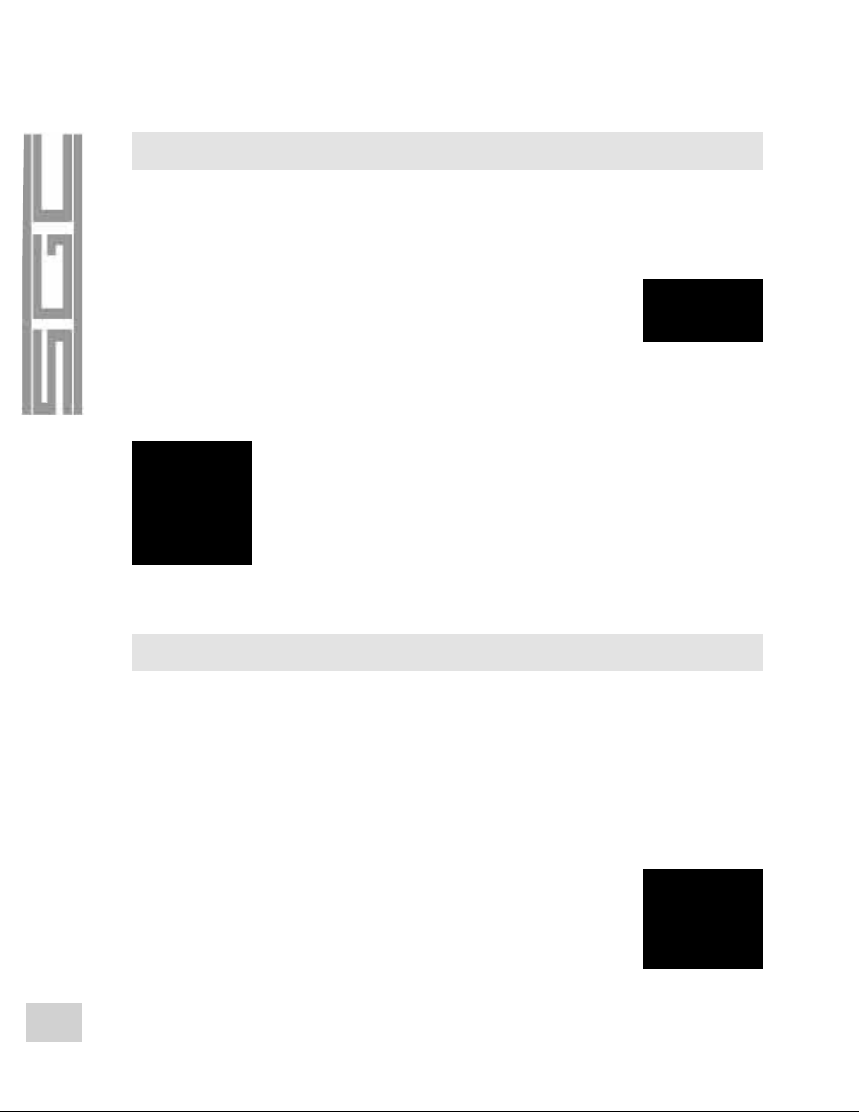
44
The SGC Building, 13737 S.E. 26th St. Bellevue, Washington 98005 USA
P.O. Box 3526, 98009 Tel: (425) 746-6310 Fax: (425) 746-6384
© 1997 SGC Inc.
There are two ways to convert 110 or 220 volts AC to 12 Volts DC, the most common DC input voltage for
transceivers. The typical methods are via conventional transformer-rectifier power supplies and switching-type
power supplies.
SGC does not recommend switching-type power supplies for continuous commercial
service for two reasons: First, unless the switching power supply is of exceptional design
and properly installed, it will generate RF "hash," which will create a high local noise level.
Second, switching-type power supplies tend to fail when used in continuous-duty operation.
Some switching power supplies are quite good. Unfortunately, they are also very expensive and are not as cost
effective as transformer-rectifier type power supplies.
Many transformer-rectifier power supplies are of the regulated type. This means that
they will hold an output voltage constant over a wide range of input voltage and output load
conditions. If regulated power supplies are not well designed, they can also create RF
"hash." This interference will create a buzz when the equipment is receiving; if the problem
is severe, a bit of this distortion could also be present in the audio when transmitting. For
this reason, SGC recommends the PS-50 regulated power supply if high current demands
(such as those encountered in operation of a transceiver) are expected.
Transformer-rectifier power supplies are by far the most reliable available. They are able to operate over a wide
range of input voltages and offer resistance to failure under periodic overload conditions, which would cause a
switching-type supply to fail.
Supply voltages for such power supplies are generally 110 and 220 volts AC with a frequency of either 50 or
60 Hz. Many aircraft also have 400 Hz AC available from their engine driven alternators, but in these instances, it is
usually better to power equipment from 24 volts (generally available on aircraft) than install a power supply to
operate equipment off the 400 Hz AC power source.
Another consideration in selecting a power supply is how much capacitance is provided
in the output of the power supply. This is important because capacitors in the output of the
power supply store electricity. Acting like batteries in this case, capacitors provide
instantaneous high peak output current.
A Regulated power
supply will hold an
output voltage constant
over a wide range of
input voltage and output
load conditions.
TRANSFORMER-RECTIFIER SUPPLIES
High Capacitance
power supplies
provide
instantaneous high
peak output current.
AC (MAINS) POWER SUPPLIES
We recommend
Transformer-Rectifier
power supplies.
Page 47

45
The SGC Building, 13737 S.E. 26th St. Bellevue, Washington 98005 USA
P.O. Box 3526, 98009 Tel: (425) 746-6310 Fax: (425) 746-6384
© 1997 SGC Inc.
High peak current is an important consideration if you are planning to operate in the voice mode. But if you
are planning to operate in the data mode or will be using the transmitter on a more continuous basis, output
capacitance is less a factor than how heavily built the transformer in the power supply is.
In virtually all mobile power supplies, the source of power is the alternator or generator system of a vehicle and
the battery. You should consider several principals of good design that affect the mobile environment when
operating from a mobile position on the HF bands.
First, HF requires quite a bit of power when transmitting. Although you can use a single battery to power both
the vehicle and the radio, SGC recommends that you install an additional battery in all cases where this is practical.
The reason for this installation is that the output voltage from a battery drops as the load increases. The more
reserve current capacity, the lower the voltage drop under high intermittent power demands.
On occasion, you will find that some vehicles operate with 24 volt DC power in the mobile and marine
services. Two approaches can be taken. First, you can install a 24 to 12 volt converter. This converter is usually
expensive. A much less expensive approach is to look for a 24 volt system that uses two 12 volt batteries in series. If
you are fortunate enough to find this type of system, simply connect the 12 volt batteries with the negative post of
one battery tied to ground, the positive lug of that battery connected to the negative terminal of the second battery,
and the positive lug of the second battery as the + volts terminal.
The extra battery will be of assistance when your vehicle is not running; then you will be able to operate the
transceiver for a varying amount of time (depending on the power output of your transceiver and how much time
you are transmitting). However, your alternator must be able to provide the power to operate everything in your
vehicle. If you are transmitting continuously, the heat is being blown by the fan at full blast, and the high beams are
on, you might be consuming more power than the power system is capable of producing. If this is the case, the
accessories will operate from the batteries until they have drained. Then, the transceiver will operate at a lower
output, the heater will produce less warm air, and the lights will probably dim. After you turn off the vehicle, you
will find that it won't start because you have drained the battery.
As a result, it is important to check the current drain of the transceiver during transmitting, plus the total current
drain of the other vehicle accessories. Add these figures together and see how they compare to the current output of
the alternator. If the drain is anywhere above just under the output of the alternator, then you should purchase a
higher powered alternator, such as those that are made for high-power car-stereo systems.
MOBILE POWER SUPPLIES
Page 48

In mobile operations, the biggest problem you will run into will be noise. Although
noise is often found in fixed locations, the mobile environment, including marine
applications, noise sources can vary, depending on the engine speed and other variables.
Noise and its removal are covered further in this user guide.
Not much needs to be said about solar charging systems, except that good design practice must be followed to
provide reliable operations under all conditions that you could expect to be encountered.
The most critical element when designing an HF solar power system is to know about the local weather
conditions. If you are designing a solar system for an area where there will be little sunlight for many days in a row,
then a large battery system and additional solar panels will be necessary. On the other hand, if you are designing
the system for an area where there is a lot of sunshine at all times of the year, then you will need fewer panels. In
some cases, two 53-watt panels and one good rechargeable gel cell battery will be sufficient.
Seasonality must also be considered. Obviously, in the high Arctic, solar power is ideal for the month or two
during the year when the sun never goes down. But in the other months, solar power is just not feasible. Hence,
another consideration should be the latitude where the solar system will be installed and a calculation of the number
of hours of daylight that will be available during the shortest days of the year.
The type of regulator that is selected to control the output of the solar panel(s) is very important. It should
operate over a wide range of loads and should continue to provide trickle charging to keep the battery system
charged to its fullest between operating sessions.
Human-powered chargers are only suitable for low-power transmitters that are in the 20-watt class and under,
such as the SG-715 manpack. Human-powered chargers will only supply a few watts of power on a continuous
basis. However, when they are used in conjunction with a battery, they provide a good means of recharging when
solar panels are not practical and other sources of power are not available.
Human-powered chargers are usually in a "coffee grinder" or "ice cream crank" configuration and are used by
one person at a time. They are not typically included in an HF installation. However, human-powered chargers are
often used for backpack transceivers in the field or in instances where periodic access to conventional re-powering
sources are not available. In amateur radio applications, modified bicycle battery chargers were a somewhat
common novelty during the early years of consumer solar panels, in the mid to late 1970's.
46
The SGC Building, 13737 S.E. 26th St. Bellevue, Washington 98005 USA
P.O. Box 3526, 98009 Tel: (425) 746-6310 Fax: (425) 746-6384
© 1997 SGC Inc.
SOLAR-POWERED CHARGERS
HUMAN-POWERED CHARGERS
Noise is the biggest
problem in mobile
operations.
Page 49

The SGC Building, 13737 S.E. 26th St. Bellevue, Washington 98005 USA
P.O. Box 3526, 98009 Tel: (425) 746-6310 Fax: (425) 746-6384
© 1997 SGC Inc.
47
HF ANTENNAS, FEEDLINES
AND GROUNDS
CHAPTER 3
Page 50

The antenna is any object that receives radio signals and inputs them to a receiver or
emits radio signals from a transmitter. As a result, during emergency or makeshift
conditions, anything from bed springs to barbed wire fences can be used as an antenna.
However, antennas are critical to good reception and transmission and the following
sections show how to build suitable antennas and what types might work best for your
situation.
It would be reasonable to expect that HF antenna systems would all be
somewhat similar. In most low-space or mobile situations, the basic HF antenna
systems are unwieldy and you would not be able to install one. However, these
antennas are somewhat flexible (from a theoretical and a physical point of view)
and by following or altering some of the basic designs, you can create systems
that will suit your needs in almost any situation. The following list shows some
of the circumstances where different types of antennas are required.
Base-station operations require the most basic full-sized antennas. Because most base stations include some
real estate, large wire antennas can usually be installed without problems.
Mobile operations require antennas that can be mounted on a moving vehicle. This rules out wire antennas.
Mobile antennas are typically derivations of the whip vertical antennas, although some others have been used,
depending on the vehicle used and the circumstances. SGC makes a full line of mobile high performance antennas,
such as the SG-303.
48
The SGC Building, 13737 S.E. 26th St. Bellevue, Washington 98005 USA
P.O. Box 3526, 98009 Tel: (425) 746-6310 Fax: (425) 746-6384
© 1997 SGC Inc.
HF ANTENNAS, FEEDLINES, AND GROUNDS
OPERATING ENVIRONMENT
In emergencies,
anything from bed
springs to wire
fences can be used
as an antenna.
BASE
MOBILE
Page 51

49
The SGC Building, 13737 S.E. 26th St. Bellevue, Washington 98005 USA
P.O. Box 3526, 98009 Tel: (425) 746-6310 Fax: (425) 746-6384
© 1997 SGC Inc.
All mobile antennas can be used for marine operations, and some (not all) base antennas can be used as well.
When installing an HF system on a ship, the key factor behind what antennas can be used is the size of the vessel. In
some cases, a standard full-sized antenna can be used, but on small vessels, whip verticals would be a better choice.
On a sailboat, the best antenna is an insulated backstay or forestay.
Typically, it is more important for field antennas to be easy to install, rather than to be compact. However,
everything depends on the goal of the operator, the environmental conditions of the location, and the length of time
that operations will be occurring from that location.
SAILBOAT
ANTENNA
PLACEMENT
KEEP LOWER
INSULATOR AS
CLOSE TO DECK
AS POSSIBLE –
JUST ABOVE
TENSIONER
CHAINPLATE
COUPLER
DECK
INSULATOR
PVC PIPE
OR SHROUD
COVER
8"
DETAIL
BACK
STAY
ANTENNA
INSULATOR
4 FEET
DETAIL
TOP
OF
MAST
FIELD
MARINE
Page 52

Aeronautical operations require antennas that are both compact and out of the way. Usually either vertical
whip antennas or wire antennas that are strung along the craft are used.
As covered much earlier in this user guide, radio signals are waves that travel through the air. Every radio
frequency is at a different wavelength because the frequency is the number of waves that pass by a particular point
in a second (radio waves all travel at the speed of light).
Many years ago it was discovered that in order for antenna systems to work correctly, they should be the same
size as or a certain fraction of the actual wavelength of the radio signal that you are listening to or plan to transmit.
This theory is known as resonance--every antenna should be cut to a resonant frequency, if possible, for best results.
The most basic type of antenna is simply a long wire, known as a longwire (brilliant deduction, eh?). It is
simply a piece of wire that is strung in a relatively straight configuration and is cut to a single wavelength for a
given frequency. If a transmitter was sending a signal into one end of this antenna, most of the signal would be
directed off of the end of the wire (away from the transmitter). The signal pattern from the end is not like an angle
50
The SGC Building, 13737 S.E. 26th St. Bellevue, Washington 98005 USA
P.O. Box 3526, 98009 Tel: (425) 746-6310 Fax: (425) 746-6384
© 1997 SGC Inc.
AERONAUTICAL
ANTENNA PATTERN BASICS
STROUT TO SPACE OUT
ANTENNA WITH
PLASTIC TUBING OR
FIBERGLASS ROD
WIRE ANTENNA
ISOLATOR
ISOLATOR
WIRE GOES TO
THE COUPLER
WIRE ANTENNA
GROUND
RADIO
AVIATION
CONTROL
HEAD
SG-230
COUPLER
WIRE ANTENN
ROTARY AIRCRAFT FIXED WING AIRCRAFT
Page 53

51
The SGC Building, 13737 S.E. 26th St. Bellevue, Washington 98005 USA
P.O. Box 3526, 98009 Tel: (425) 746-6310 Fax: (425) 746-6384
© 1997 SGC Inc.
that spreads out; the pattern actually shows lobes that shoot out from along the wire (but not right off the end). If
you looked at the pattern from the end of the wire, it would look something like a doughnut.
The signal emission pattern changes depending on how high above the ground it is. If
the wire is placed anywhere from a 1/2 wavelength off the ground or higher, the pattern will
remain almost perfect. As the wire gets closer to the ground from the 1/2 wavelength figure,
the pattern becomes more skewed.
Another way to change the signal pattern from the antenna is to add another wavelength to the wire, thus
making it two wavelengths long. Now the lobes are tighter, more numerous, and at an angle that is even closer to
that of the antenna wire.
Objects always appear different when you look at them from a different angle. So, now imagine that the
original one-wavelength wire is no longer horizontal, but is now vertical, with the end at the ground being fed by the
transmitter. The pattern from the antenna is the same and the angle by which the signal
leaves the antenna is the same. A figure that is related to this angle is the angle of
radiation, which is the angle that radiation leaves the antenna, with the horizontal land
plane (not the antenna) as the reference. The angle of radiation is important because of the
bending of the signal in the atmosphere. If the angle of radiation is "low," then the signal
will reach the ionosphere at a large distance from the transmitter site, the angle by which
the signal is refracted will be wide, and the distance to the first hop will be equally distant. The opposite will be true
of the angle of radiation is high. As a result, antennas with low angles of radiation are preferable if long distance is a
must and antennas with high angles of radiation are better for short-distance communications.
As you could see from the one-wavelength horizontal longwire antenna, the signal was being emitted in a
particular direction. And as the antenna grows in wavelengths, the transmission characteristics become even more
directional. As a result, antennas such as the longwire are important if you are trying to
communicate with station(s) from a particular direction. If you want to reach all directions
equally well, then an antenna (such as a vertical) would work best. The radiation pattern from
the vertical antenna (as described in the previous paragraph), is toward the sky, but from a
"doughnut" pattern around the wire. This all-sides-equally-well pattern is known as being
either omnidirectional or nondirectional.
The illustrations that have been covered so far in this section only cover signal transmission patterns. However,
you can expect that any good transmitting antenna will also be a solid antenna for receiving. Likewise, receiving
antennas will have the same general characteristics for receiving as they would for transmitting. For example, if a
directional antenna produces a particular set of lobes when transmitting, the directions that those lobes face will be
where the antenna receives best from (if you aim your antenna so that you can transmit to Europe, that antenna will
also be best poised to receive signals from Europe). As you can see, the receiving characteristics of antennas are so
Angle of Radiation:
the angle that
radiation leaves an
antenna, with the
horizontal land
plane as a
Omnidirectional or
Nondirectional
antenna: radiates
an "all-sides-
equally-well, donut-
shaped, pattern".
The Signal Emission
Pattern changes
depending upon its
height above the
land or sea.
Page 54

52
The SGC Building, 13737 S.E. 26th St. Bellevue, Washington 98005 USA
P.O. Box 3526, 98009 Tel: (425) 746-6310 Fax: (425) 746-6384
© 1997 SGC Inc.
abstract that they are difficult to illustrate without showing their transmitting patterns. Just remember that although
every good transmitting antenna is a good receiving antenna, not every good receiving antenna is a good
transmitting antenna. And, every receiving antenna carries practically no power, while every transmitting antenna
carries RF power. More on this in a following section.
If you are spreading your signal in all directions through a nondirectional antenna, then your signal would not
be concentrated. However, if you use a directional antenna, then your signal is being
concentrated in a particular area. This concentration is said to be the gain of the antenna.
Many manufacturers use the term gain for comparative elements from one configuration or
situation to another. They should be clearly understood before using comparatives in a
system design or specific application.
One other important difference between the vertical wire and the horizontal wire is the
polarization of the signals as they are being transmitted and received. Radio wave
polarization is quite complex, but you can assume that if your transmitting antenna is
horizontal, then your signal will be horizontally polarized. The same line of reasoning holds
true for vertical antennas. However, propagation can alter the effects of polarization and
either turn it upside down or turn it sideways so that the signal is diagonally polarized.
Polarization is not of great importance, but an antenna will generally receive a bit better if it is of the same
polarization as the signal that is being received.
Thus, if several stations that you must frequently contact use vertical antennas (vertical polarization), then you
might consider using a vertical antenna as well. This theory can hold its own in some cases, but different factors can
overrule it. For example, if you want to contact a low-power station from the other side of the world, you would be
better off having a longwire pointed right at the direction of the station than to have a vertical antenna. The positive
effects of the longwire's gain would outweigh the fact that the antenna is of the opposite polarization. Also, at such a
great distance, it is likely that the signal would be refracted with some parts of the signal being vertically polarized,
some parts horizontally polarized, and some parts diagonally polarized. By this point, it wouldn't really matter how
your antenna was polarized. As a result, the manner in which your antenna is polarized is not one of the major
factors in deciding which HF antenna you should choose.
Thus far, all of the antennas have had one single element. Although there isn't enough space to cover it all here,
all antennas consist of antenna elements and grounds or ground elements. The resonant antennas (those that are cut
for a specific frequency) have ground elements and the nonresonant antennas require an excellent ground system
(covered in a further section) to perform well. The two antennas covered in this section (the
horizontal wire and the vertical wire) could be made as a balanced antenna if a halfwavelength of wire was cut in half; one section would be connected to ground and the other
half to the "hot" transceiver lead. Or the antennas could be left as unbalanced antennas. In
this case, the ground lead from the transceiver would be connected to an excellent ground.
Antenna Directivity:
when using a
directional antenna,
the concentration
of signal in a
particular area.
An antenna will
generally receive
better if it is of the
same polarization
as the signal that is
being received.
Resonant or non-
resonant antennas
require a
ground system.
Page 55

Although some of the basics of antenna construction and materials are covered here, this is not meant to be a
definitive course on building your own antennas. Many books have been written about antenna construction and you
could easily fill a few volumes on the subject. Instead, this section is mostly just intended to help you to choose the
type of antenna that would best work in your situation, and how that antenna should be constructed. For further
information on basic receiving antenna construction, see Build Your Own Shortwave Antennas (2nd Edition) by
Andrew Yoder from TAB/McGraw-Hill. Note, however, that this reference is not intended for transmitting antennas.
Most typical HF antennas are large (or at least long) because of the very long wavelengths of these signals. For
example, a full wavelength at 30000 kHz is 30 feet 14 inches and a full wavelength at 1700 kHz is a whopping 550
feet 8 inches! Because of the lack of space for such large antennas, most are designed to be either a half or a
quarter wavelength. Because of the large size and the low power levels involved (usually under 1000 watts for most
HF installations), most HF antennas (except for the mobile whips and the rotatable antennas) are constructed out
of wire.
Different types of wire can be used for HF antennas, but generally stranded copper wire is the best. Copper is
the best low-cost conductor (don't even think about using stranded silver, platinum, or gold!), so it allows more of
your signal to pass from the conductor to the air. Also, it is strong, won't easily stretch (unlike aluminum wire), and
won't quickly corrode away (unlike steel or iron). Stranded, rather than solid, wire is the best because the wires will
probably be bending and swaying in the breeze for most of their time in the air. As a result, an antenna made from
solid copper wire will break much quicker than one made from stranded copper wire.
The gauge of the wire is a factor that is important when constructing a transmitting antenna, but not a receiving
antenna. The importance of the wire gauge relates to a principle known as skin effect. Skin
effect is an interesting principle, whereby all of the signal from the transmitter is
concentrated on the outside ("skin") of the wire. Beyond a certain breakdown surface areato-signal ratio, the wire will begin to heat up. In one instance, a broadcast engineer was
using over 1000 watts into a small-gauge dipole antenna. The wire gauge was too small to
support the output power, and the wire heated up. After a few minutes of transmitting, the antenna wire burned up
and the remains of the dipole fell to the ground! For best results with powers under 1000 watts, you should use any
of the following wire gauges: #6, #8, #10, or #12.
The gauge of the wire also has an impact on the usable bandwidth of the antenna. The bandwidth is the
frequency range within which the antenna can be used for transmitting (without any matching devices) or most
effectively used for receiving. The bandwidth depends on the type of antenna that is used, the gauge of the wire, and
several other factors. A typical antenna for base operation can be used for approximately 200 to 300 kHz above and
below the frequency that it is cut for. The problems of having your antenna out of resonance are that it causes high
SWR, which is covered further in one of the following sections.
53
The SGC Building, 13737 S.E. 26th St. Bellevue, Washington 98005 USA
P.O. Box 3526, 98009 Tel: (425) 746-6310 Fax: (425) 746-6384
© 1997 SGC Inc.
The Bandwidth is the
frequency range
within which the
antenna can be used
for transmitting.
ANTENNA CONSTRUCTION BASICS
Page 56

54
The SGC Building, 13737 S.E. 26th St. Bellevue, Washington 98005 USA
P.O. Box 3526, 98009 Tel: (425) 746-6310 Fax: (425) 746-6384
© 1997 SGC Inc.
Sometimes people become confused about skin effect or hear some tall tales of antenna design. Skin effect is
the subject of many tales. One of the best stories involves the tarnish on non-insulated copper wire. A radio hobbyist
insisted on non-insulated wire (because the insulation would prevent the signal from leaving wire as easily) and he
would even pull down his wire and sand the tarnish off every spring (for the same reason)! Tarnish and insulation
on an antenna conductor will not hinder its performance. In fact, most people prefer insulated wire better because
they frequently move and replace antennas. The insulated wire slides through trees better and you're not as likely to
cut your hand on a broken strand. Also, insulation protects anything from being burned by the signal that is being
transmitted through the antenna. There's nothing like bumping into a "hot" antenna and getting a nice RF burn
across an arm or leg.
Over the century since radio has been discovered, hundreds (if not thousands) of antennas have been used with
varying degrees of success. The antennas included in this section are some of the most popular. Some of these
antennas are merely variations on another type. Others are variations, but are used in such peculiar circumstances
that they are always considered to be separate types of antennas. Regardless of the style, the shape, or the
construction of the antennas, the wavelength for radio frequencies is always determined with the same equation:
l (length in feet) = -----------------------
However, you will notice that most antennas are half-wave or quarter-wavelength. For these antennas, the
length is exactly 1/2 of the length that you would determine from the equation above. Even if you are not planning
to build your own antenna system, the equations and specifications included here will help you to determine the
length and determine whether you have the space available to install one or more.
The longwire was used as an example for the beginning of the antenna section. The
standard longwire is an unbalanced antenna that is several wavelengths long for the
frequency that it is to be used at. Longwires are typically used because of their excellent
directional properties. Dedicated amateur radio operators and professional monitoring posts often install an array of
these antennas in a half circle, with the ends all pointing in different directions. However, few people have the land
to install antennas that cover several thousand feet in all directions.
ANTENNA TYPES
LONGWIRES AND RANDOM-LENGTH WIRES
936
f (frequency in MHz)
Longwire antennas
have excellent
directional properties.
Page 57

55
The SGC Building, 13737 S.E. 26th St. Bellevue, Washington 98005 USA
P.O. Box 3526, 98009 Tel: (425) 746-6310 Fax: (425) 746-6384
© 1997 SGC Inc.
The longwire (or arrays of longwires) is used by serious radio users with a big commitment to radio and its
operations. The random-length wire is the opposite; it's a relatively short wire that is used when you just don't have
the space or money to install a better antenna. Unlike the longwire, the random-length wire is often much less than a
wavelength for the frequency at which it is to be used These antennas are also not as effective as others and they
require an antenna matching or tuning device for proper use. However, HF communications are most important for
portable, mobile, and emergency situations. At these times, you can effectively use a random-length wire antenna
with an SG-230 Smartuner™ for short- or long-distance communications.
These two antenna types are the complicated big brothers to longwire antennas. The vee antenna consists of
two longwires that are separated by an angle of approximately 45 degrees. These two wires are connected to the
transceiver via ladder line (covered in the section on feedlines). When a single frequency is used, use a coupler
(such as the SG-230) in the center of the antenna and fed by a 50 ohm cable. Vees are very directional and are
typically only used in situations where this focused antenna power is necessary.
The rhombic is basically two vee antennas connected together at the tips of the widest points to form a
diamond. Instead of having another section of ladder line at the far tip of the antenna, a resistor connects the two end
elements and runs to ground. Rhombics require so much land and are so directional that that they are rarely used,
except by shortwave broadcast stations that need to beam their signal to certain parts of the world.
The Marconi family of antennas are some of the oldest types in existence. These antennas were developed by
Guglielmo Marconi near the turn of the 20th century during his extensive radio experiments. The Marconi antenna
family contains any antenna that has a "hot" quarter-wave element and the other side of the transceiver is connected
to ground. The most common Marconi antenna is the quarter-wave vertical (see the next entry), but one of the old
classics from the 1930's is the inverted L. With the inverted L, the first 1/8 wavelength of the wire element is
vertical and the other 1/8 wavelength is horizontal. Because of its bent element, the antenna radiates both vertically
and horizontally polarized waves. These days, the inverted L has mostly been forgotten, but is one of the most
efficient and highly recommended by SGC.
VEES AND RHOMBICS
Page 58

56
The SGC Building, 13737 S.E. 26th St. Bellevue, Washington 98005 USA
P.O. Box 3526, 98009 Tel: (425) 746-6310 Fax: (425) 746-6384
© 1997 SGC Inc.
This antenna is commonly used by CB'ers, public service radio operations, AM broadcast stations, and others.
Typically, the quarter-wave vertical has one vertical element (the "hot" or radiating element) and the ground side is
connected to a system of ground radials. Although this antenna has been criticized as "radiating poorly in all
directions," the key to a good quarter-wave vertical is an excellent ground system. For the high-frequency versions
of this antenna, a counterpoise ground is used. The counterpoise is a mock ground, where the ground radials are
located in the air with the antenna, instead of being buried in the ground. This system is best because the antenna
can be placed on a mast high above the ground, however, it just isn't feasible for frequencies below about 21 MHz.
4 WIRES FOR
GROUNDING
CONNECTED TO
BASE OF
ANTENNA ON
NON-METAL ROOF
FOR LIGHTENING SAFETY GROUND
ANTENNA WITH LARGE GAUGE WIRE
IF POSSIBLE
ROOF BASE
MOUNT
MONOTUNE
ANTENNA
USE METAL STAYS FOR
GROUNDING PURPOSES
FLAT ROOF
MOUNT
RADIO
COUPLER
ANTENNA
CONNECTIO
GROUND RADIALS
THE QUARTER-WAVE VERTICAL
FOR LIGHTNING SAFETY GROUND
ANTENNA WITH LARGE GAUGE
WIRE
IF POSSIBLE
Page 59

57
The SGC Building, 13737 S.E. 26th St. Bellevue, Washington 98005 USA
P.O. Box 3526, 98009 Tel: (425) 746-6310 Fax: (425) 746-6384
© 1997 SGC Inc.
The whip antenna is a space-saving version of the quarter-wave vertical. To save space, the wire antenna
element is usually wound around a fiberglass whip and loading coils are added to make the transceiver "think" that a
full-sized antenna is at the other end. Overall, the system works and it is quite possible to have regular
communications from a vehicle with a whip antenna. However, the whip is certainly not the best antenna that could
be used in an open, fixed location. In this case, the whip would be one of the poorest choices.
The Windom antenna is another form of the Marconi antenna. Standard, unmodified Windoms are peculiar
relics from the pre-World War II days of radio. Rather than being fed with feedline, Windoms are fed by the "hot"
output of the transmitter with a single wire; the other side must be fed to an excellent ground. The feeder or coupler
(i.e. SG-230) is connected to an off-center point (usually 36% of the way across) a quarter-wave element. Like all
Marconi antennas, the Windom must have an excellent ground in order to work properly. The Windom has been
occasionally revamped and altered over the years; they are not covered here because most are complicated and some
of these varieties have been modified to the point that they are no longer even true Marconi antennas.
The dipole is one of the most basic
and popular antennas ever for HF
applications (especially for frequencies
below 10 MHz). This balanced antenna
consists of two quarterwave pieces of
wire that are fed in the center by a piece
of coaxial cable to the transceiver. The
most common configuration for the
dipole is horizontally. In this manner, it
radiates best in two approximate
directions, though it is not considered to
be a directional antenna. However, the
dipole can be turned on its end and be
THE VERTICAL WHIP
THE WINDOM ANTENNA
THE DIPOLE AND ITS VARIATIONS
BASE DIPOLE
INSTALLATION
SG 215/230
AUTO
COUPLER
7 TO 25 METERS
E66 INSULATORS (X8)
1 METER
3 METERS
3 METERS
HOT
CND
GND
Page 60

58
The SGC Building, 13737 S.E. 26th St. Bellevue, Washington 98005 USA
P.O. Box 3526, 98009 Tel: (425) 746-6310 Fax: (425) 746-6384
© 1997 SGC Inc.
used as a vertical. The vertical dipole is more unwieldy than the quarterwave vertical, so it is less popular. Each end
of the dipole can be dropped to form an inverted vee (the angle between the inverted vee should be about 120
degrees). The inverted vee has a slightly different radiation pattern than the standard dipole, but it is usually used
because only one support in the middle (not three) is required to keep it in the air. The last standard variation of the
dipole is the sloper. The sloper is a dipole that extends from one support in the air to the ground at about a 45 degree
angle. Four slopers are sometimes placed around each direction of a flag pole or other support to form a small-space
directional antenna array.
The building block of the beam and the Yagi antenna is the horizontal dipole. The theory behind these
antennas are that if you place another similar antenna element a certain distance away and parallel to that element,
the antenna will become more directional. Typically, one slightly smaller element is placed 0.25 of a wavelength to
the one side of the dipole, and one slightly larger element is placed 0.25 of a wavelength to the other side of the
dipole. The two elements are both called parasitic elements because they only guide the signal to the "real" antenna.
The smallest element is the director, the center is the driven element, and the largest is the reflector. This threeelement beam or Yagi antenna is usually made from aluminum tubing and is then typically placed on a rotor so that
it can be turned. These antennas are some of the best rotatable directional antennas that are available, so they are
excellent
for limited-space applications if frequencies above 14 MHz are used (below this range, the long elements
become unwieldy).
The log-periodic is another derivative of the standard horizontal dipole. Instead of having director and reflector
elements, the log-periodic antenna has a number of elements that are all interconnected. These elements vary in size
from the front element (smallest) to the rear element (largest). Thus, nearly every element in the array works as a
director, driver, and reflector at the same time. The number of elements in log-periodic antennas vary, although they
can often contain as many as 12 or 15 elements. Because of the large number of tuned elements, log-periodic
antennas are very directional. These antennas are very big, so they are generally used in fixed locations by
broadcast and government stations that must beam a signal to a particular part of the world.
BEAM AND YAGI ANTENNAS
LOG-PERIODIC ANTENNA
Page 61

59
The SGC Building, 13737 S.E. 26th St. Bellevue, Washington 98005 USA
P.O. Box 3526, 98009 Tel: (425) 746-6310 Fax: (425) 746-6384
© 1997 SGC Inc.
Most of the antennas described to this point have been
some derivative of the dipole, longwire, or quarter-wave
vertical. The loop antenna is a different type of antenna that
has its own family. Typically people think of loop antennas
as being small square boxes with several turns of wire
wrapped around the outside. This type is somewhat common,
but the most common type is the loopstick antenna, where
space is conserved by wrapping wire around a pen-shaped
piece of ferrite. Loopstick antennas are used in nearly every
AM broadcast radio receiver on the market. Although these
two types of loop antennas are poor for transmitting into,
they are excellent for receiving. On the downside, loop antennas provide very weak signals to the receiver, so a
preamplifier is required to boost the signal to the receiver. The best aspect of loop antennas is that they are
extremely directional when small, and they can be small enough to easily rotate by hand. When large, these antennas
are less directional.These two forms of loop antennas are used by hard core AM broadcast listeners and by people
who need to direction-find transmitters (radio enforcement, etc.).
Boxes and deltas are both forms of the loop antenna. Like the other loop antennas, the "hot" side of the output
from the transmitter is connected to one side of the loop and the "ground" side is connected to the other side of the
loop. Unlike the previous loops, only one loop of wire is used and these are excellent for use when transmitting.
The only difference between the box and the delta antenna is that the box is a four-sided loop and the delta is a
three-sided loop (likewise, the antenna patterns differ a bit). These two antennas are somewhat directional and they
are excellent for use in small-space locations, where several trees and a length of about 20 to 40 feet are available,
but not much else.
RADIATION
SG-230
COUPLER
BASE DELTA LOOP
LOOP ANTENNAS
BOXES AND DELTAS
Page 62

60
The SGC Building, 13737 S.E. 26th St. Bellevue, Washington 98005 USA
P.O. Box 3526, 98009 Tel: (425) 746-6310 Fax: (425) 746-6384
© 1997 SGC Inc.
To imagine a cubical quad antenna, think of how a dipole relates to a beam. The typical quad features three
loop antennas on a crossbar. Like the beam, one of the loop elements is slightly smaller (the director), one is larger
(the reflector), and the one in the middle is the active element (the driver) that is connected to the transceiver. The
quad was developed by a broadcast station in Ecuador in the 1930's. The thin Andes air was causing the voltages to
arc off of the ends of the station's beam antenna. To prevent the arc-over, the station engineer made the elements
into loops so that the signal couldn't arc-over. Quads and beams are quite similar, but each type has a group of
followers.
A few of the antennas that are listed in this section can be used for mobile installations in vehicles, aircraft,
and boats. The most popular mobile antenna, the vertical whip, was already listed. However, several unconventional
types of antennas can be designed or modified for these installations. With the SG-230 Smartuner™, different
random-wire antennas can be run along the top of a large vehicle, such as a van or truck, or from one part of an
airplane to another. In the case of the random wire on a vehicle, the wire would have to be held above the metal roof
with stand-off insulators. As an example of operator creativity, I even heard of one case, where a tractor-trailer
operator installed a dipole on stand-off insulators above the trailer. Marine vessels are often ideally suited for
BASE QUADRA
LOOP HORIZONTAL
PORCELAIN
ISOLATORS
WITH TIE ROPE
RADIATION
SGC-230
COUPLER
50 Ω
FEED
CABLE
GROUND
BOLT
TERMINAL
ANTENNA
PORCELAIN
TERMINAL
QUADS
MOBILE ANTENNA VARIATIONS
Page 63

61
The SGC Building, 13737 S.E. 26th St. Bellevue, Washington 98005 USA
P.O. Box 3526, 98009 Tel: (425) 746-6310 Fax: (425) 746-6384
© 1997 SGC Inc.
installing HF antennas. Of course, whip antennas can be installed on the higher parts of the boat, and because the
vertical height of the boat is of little importance, you can install much larger vertical antennas than would be
possible on a vehicle. Also, the natural contours of most boats make random longwire antennas a possible choice.
Feedlines (sometimes also known as transmission lines) are the cables that carry radio signals from the
transmitter to the antenna or from the antenna to the receiver. Feedlines are very important for transmitting because
a "lossy" feedline could allow most of your signal to "drain" away or cause technical problems that could reduce the
transmitter output portion of your transceiver.
Not only must these feedlines carry your signals back and forth between the antenna
and the transceiver, but they must create a match between the antenna and the transceiver.
What must be matched is the impedance of any given system. The impedance is the
SG-230
COUPLER
MOUNTED
INSIDE COACH
RECREATIONAL VEHICLE
ANTENNA INSTALLATION
18" PVC PIPE
STAND OFFS
METAL ROOF
OF VEHICLE
ANTENNA WIRE
USE A SEPARATE GR OUND STRAP OR WIRE FOR THE BODY AND
THE CHASSIS TO THE GROUND OF THE COUPLER
FEEDLINES
Impedance must be
"matched" in an
HF system for
proper operation.
Page 64

62
The SGC Building, 13737 S.E. 26th St. Bellevue, Washington 98005 USA
P.O. Box 3526, 98009 Tel: (425) 746-6310 Fax: (425) 746-6384
© 1997 SGC Inc.
opposition to a signal flow through a component or a line. Overall, the theory of impedance in radio systems is
beyond the scope of this user guide. All you need to know is that the transceiver output, the feedline, and the
antenna all have their own characteristic impedances, and for proper transfer of power, should all be the same.
The problem with these
characteristics is that they must all
match. If they aren't at least close
in value, a mismatch will occur.
For example, if the transmitter
and the feedline are both 50 ohms
and the antenna is 100 ohms, a
portion of the power coming from
the transmitter, which should be
radiated by the antenna, will be
"reflected" back toward the
transmitter. This radiation, which
is developing on the feedline, is
known as standing waves. The
ratio of the peak voltage going to the antenna and the measured peak voltage reflected back to the transmitter is
called the standing wave ratio (SWR).
When the SWR exceeds about 2:1, the HF transmitter will reduce power to reduce the stress on the
components. Reflected power has nowhere to go, so it is turned into heat. This heat can be dissipated by the feedline
or it can be dissipated by the components in the output circuit of the transmitter. Either way, one of the rules of HF
equipment is "heat is bad!" When older transceivers and transmitters were under high SWR
conditions, they would continue operating at the same power level and gradually (or not so
gradually!) damage or destroy the final output tubes.
You could change the characteristic impedance of the transceiver to match the antenna,
but you would have to tear apart the final stages of the transmitter. Modern transceivers have
a connector that is meant to connect coaxial cable feedline. Coaxial cable has a center
conductor that is surrounded by an insulating dielectric material. That material is surrounded by a grounded copper
braid, which is wrapped in an outer insulating sleeve. The output of modern transceivers is rated at 50 to 75 ohms.
The easiest method to get a matching impedance on the feedline is simply to use a type
of coaxial cable that has an impedance of from 50 to 75 ohms. Some of the most frequently
used types of coaxial cable for HF use are RG-8, RG-8X, and RG-58. The last ways to get
the impedance to match up properly are to use an antenna with a characteristic impedance of
50 to 75 ohms and make sure that the antenna is cut to the frequency of operations. The most
ANTENNA
C OUTC IN
50 ohms
L1
Standing Wave Ratio
(SWR): the ratio of the
peak voltage going to
the antenna and the
measured peak voltage
reflected back to
the transmitter.
To obtain a matching
impedance on the
feedline, use coaxial
cable with an
impedance of 50
to 75 ohms.
Page 65

63
The SGC Building, 13737 S.E. 26th St. Bellevue, Washington 98005 USA
P.O. Box 3526, 98009 Tel: (425) 746-6310 Fax: (425) 746-6384
© 1997 SGC Inc.
common antennas that can be fed with coaxial cable (and not require any matching devices) are those in the
dipole family.
With coaxial cable, the grounded shield prevents interference from entering the "hot" center conductor and it
keeps the transmitted signal from leaking out through the line before it can be radiated by the antenna. Coaxial cable
is an unbalanced line; the signals traveling down each side are not the same.
The antennas in the longwire group (for example) all require either twin lead, open wire, or ladder line
feedline. These types of feedlines are all types of balanced lines. Balanced lines are merely two (or sometimes four)
parallel conductors that are separated by a particular distance (usually anywhere from one inch to a few inches).
Balanced lines don't have any shielding because they don't need any; having the same signal running down each line
keeps the lines balanced and prevents them from radiating the signal. No transceivers have outputs for balanced
lines; if you want to use this type of transmission line, the most common solution is to run a short piece of coaxial
cable to an SG-230 Smartuner™, which will solve the problem.
Another solution is to use a balun in line with the antenna. A balun is a contraction of balanced-unbalanced.
The system features a transformer that matches the impedance of the 50-ohm output of the transceiver to the 300 or
600 ohm antenna, depending on the value of the balun that you choose. Most commercial baluns are small cans that
screw into the coaxial cable at the connection between the antenna elements. Not only do these baluns improve
performance, but they are constructed so that it is easier to build the antennas.
The most important characteristic to look for when purchasing balanced feedline (or an antenna that uses
unbalanced feedline) is strength and flexibility. If it looks like it will last in the elements, use it. Coaxial cable is a
much trickier purchase. Every component within the cable is essential to good operation. First, the center conductor
should be of a heavy enough gauge to handle transmitting powers (usually about #16 or thicker). Next, you should
make sure that the insulating dielectric is strong and won't break down in the presence of heat or water. The most
important option is to make sure that the shield is made from a solid copper braid that covers 95% (or better) of the
cable. Without this high-percentage, low-loss braid, some of your power will drain out through the coaxial cable.
The last part of the cable is the outer sleeve, which must be strong, flexible, heat-resistant, and resistant to ultraviolet
rays. In this era of increased environmental awareness, coaxial cable is one product that can't be biodegradable!
The safest way to choose good-quality coaxial cable is to pick a type that is made according to industrial or
military specifications.
Page 66

64
The SGC Building, 13737 S.E. 26th St. Bellevue, Washington 98005 USA
P.O. Box 3526, 98009 Tel: (425) 746-6310 Fax: (425) 746-6384
© 1997 SGC Inc.
When working with HF transceiving systems, it is very important to have two types of grounds. The first type
of ground is simply referred to as a ground or as an equipment ground. This type of ground is very important to
reduce external interference in your system and prevent nasty electrical shocks if a piece of your equipment should
happen to fail and make the chassis, knobs, or switches "hot." The other type of ground is the RF ground, which is
necessary to obtain good performance while transmitting.
An equipment ground is only essential to avoid electrical shock from the main AC line. Since most equipment
is operated from 12 volts DC, it is important to have the DC power supply grounded properly to the AC neutral
ground. Grounding the radio transceiver to a nearby metallic structure is not always recommended, because that
structure or ground may be polluted with appliance or RF industrial noise. Making this connection may
significantly increase the noise level captured by the receiver. Make the final connection only after testing your
system for proper operation and only then, if necessary.
As was stated earlier, RF grounds are necessary for an effective transmitting system when using Marconi
antennas with balanced feedlines. Unlike some other less-tangible radio theories, the physical laws behind why
grounds improve transmission efficiency are easy to understand because it is exactly the other half of your
transmitting line system. For example, if you need to supply power to your car headlight from the battery you need
a positive wire (your antenna) and a negative wire to return to the battery (your RF ground). It is that simple
because one will not work without the other.
RF grounds differ both in function and design from standard equipment grounds. The most important concept
is that RF grounds can be tuned to resonance at a major frequency of operation (just like antennas) to be effective.
To be on the safe side, a groundwire has to be at least the same length and diameter as the antenna (refer to a dipole
antenna). However, it is recommended to use several lengths of wires of a size not less than the antenna to make
your own ground system. The great advantage to making your own ground system is that you know exactly what is
there and generally you can isolate it from any polluted appliance or industrial grounds.
GROUNDING SYSTEMS
EQUIPMENT GROUNDS
RF GROUNDS, COUNTERPOISES, AND GROUND PLANES
Page 67

65
The SGC Building, 13737 S.E. 26th St. Bellevue, Washington 98005 USA
P.O. Box 3526, 98009 Tel: (425) 746-6310 Fax: (425) 746-6384
© 1997 SGC Inc.
The grounds for base station operations generally require the most work, but they are
also the most effective. The best ground starts with wire radials longer than the antenna and
at least the same size or larger in diameter than the antenna wire. Make sure that the wires
have both a solid physical and electrical connection. For best results, 12 or more of these
wires should be spaced evenly as they radiate out from the center pipe. As a result of this pattern, the ground wires
are typically called radials. There is no real limit to the number of radials that can be buried; some amateur radio
operators who use the 160-meter band (approximately 1850 kHz, where a quarterwave radial would be 126.5 feet)
literally have several miles of ground wire buried in their yards.
The wires should then be buried several inches in the ground. The depth of the radials makes no difference in
the performance of the ground; the most important thing is that they are making good contact with the ground and
that they are buried deep enough to prevent people from tripping on them (and possibly hurting themselves or
damaging the ground in the process).
To maximize the ground's performance, and especially for ground wave, it is best to have high ground
conductivity. Ground conductivity is simply the measure of how electrically conductive your soil is. Water and
metals are all very conductive and salt improves conductivity. As a result, the best location (as far as a ground is
BASE STATION GROUNDS
CONDUIT FOR
CONTROL CABLE
AND COAX
GROUND CABLE NO. 4 AWG
(150 CM MAX)
RADIAL WIRES
BURIED IN SOIL
30°
30°
11M
2M
INSULATOR
INSULATOR
GTO CABLE
TUNER
2M
BASE INSTALLATION WITH GROUND WIRE RADIALS
A superior Base
Station equipment
ground consists of 12
or more Radials.
Page 68

66
The SGC Building, 13737 S.E. 26th St. Bellevue, Washington 98005 USA
P.O. Box 3526, 98009 Tel: (425) 746-6310 Fax: (425) 746-6384
© 1997 SGC Inc.
concerned) that you can operate from is a salt marsh. Salt marshes aren't overly abundant, so other methods are used
to improve the conductivity of the soil and the performance of the ground. One method is to remove several inches
of soil for the entire circular area where the ground radials are to be set. Then wire mesh is unrolled over the area.
Afterwards, the ground radials are installed and the dirt or sod is laid overtop. This system improves the
conductivity considerably. Another method is to spread rock salt in the ground around
the radials and the center pipe. The problem here is that the salt will corrode the
ground system quicker than if it was buried in relatively salt-free soil.
If you are out in the field for an extended period of time, you will need to communicate
with other stations and some sort of ground system will probably be necessary. However, the
time and cost involved to install a large grounding system just isn't practical. This is where
the counterpoise or a ground radial wire set is handy. As stated previously, a counterpoise is
an artificial ground. One of the most common types of counterpoises is basically the same as the buried ground
radial system that was described in the previous paragraph. This system, however, is staked above the ground level
and it consists of approximately 8 ground radials. Either wooden or metal stakes can be used, and they should hold
the ground system at anywhere from one foot to several feet off of the ground level. If you take some care with
winding the radials up after each use, you should be able to install and remove one of these counterpoise ground
systems in between 30 and 45 minutes
High Ground Conductivity
maximizes a ground's
performance.
FIELD-OPERATION GROUNDS
A Counterpoise--an
artificial ground--is
preferred for most
operations.
BASE INSTALLATION
GROUND LEAD
1.5M MAX
7M to 10M
GROUND ROD (3M)
Page 69

67
The SGC Building, 13737 S.E. 26th St. Bellevue, Washington 98005 USA
P.O. Box 3526, 98009 Tel: (425) 746-6310 Fax: (425) 746-6384
© 1997 SGC Inc.
Mobile grounds are particularly critical because it is difficult to install a system on
such a small area that is moving. Even though vehicles are constructed from steel, the
amounts of metal per car are decreasing each year, as plastics are used more. Even though
large amounts of metal are still used in vehicles, some metal parts are isolated (insulated)
by plastic or paint. As a result, even if you attach the ground cable to bare metal on the vehicle, you are not
guaranteed of a solid mobile ground. Your best bet is to attach the ground strap to the chassis and make sure that
they are making a good electrical connection. To do this, clean the metal with a wire brush, then fasten the ground
with a self-tapping sheet-metal screw. After you have finished tightening the screw, spray the connection with a light
coat of weather-proof spray paint to protect the connection from corrosion.
To further improve the ground mass, ground the doors, hood, and trunk lid to the vehicle's chassis using a #0 (or
larger) ground braid. Another
improvement is to check the exhaust
pipe and ground it properly. These
tasks will all improve the ground (and
improve the efficiency of your
transmissions) and reduce the
possibilities of interference while
receiving.
If you typically operate the
vehicle for several hours from a parked
location, a quick counterpoise ground
might be a convenient solution. In this
case, you would have 4 or so ground
radials installed on the back of the
vehicle. Whenever you reached a
parked location for transceiving, you
could unroll the wires and hold them
with stakes. This wouldn't be an ideal
counterpoise ground, but it would be a
decent system for semi-mobile
operations. By the same token, you
may attach a longwire to your existing
mobile antenna.
MOBILE GROUNDS
The best vehicle
ground is to attach
the ground strap to
the chassis.
POWER &
RF COAX
CABLE
COUPLER
HIGH
VOLTAGE
WIRE
HIGH VOLTAGE &
WATERPROOF
FEED THROUGH
VEHICLE OR
VESSEL BODY
9 FOOT WHIP
ANTENNA
RATCHET
MOUNT
GROUND
CONNECTION
PORCELAIN
ANTENNA
CONNECTOR
Page 70

68
The SGC Building, 13737 S.E. 26th St. Bellevue, Washington 98005 USA
P.O. Box 3526, 98009 Tel: (425) 746-6310 Fax: (425) 746-6384
© 1997 SGC Inc.
Bonding, as it is called in marine circles, is the process of tying all vessel metal into
a single electrical point. The reason for this bonding is that for an HF antenna to radiate
properly, a larger ground system than the antenna must be present. This installation is not
difficult, but you must be willing to invest some time. The recommended bonding
material is copper foil or wire, which is available in several different widths. However, you should always route the
foil in such a way that you can keep all leads direct. Other materials are sometimes used for the boat grounding, but
these are subject to corrosion and marine growth. There is no substitute for lots of copper (except lots of silver,
platinum, and gold)!
If your boat has a fiberglass hull, line the inside surface of the hull with a large area of copper foil. If the foil is
separated from the sea by 1/2 inch or less, the copper will form a capacitance bond with the
water and work as a very effective ground. If the hull is made from aluminum or another
type of metal, you are almost guaranteed of an excellent ground - especially if the boat is
sailing in salt water. Just attach the ground strap or a piece of copper foil (that is at least
several inches wide) from the transceiver to the hull.
SAILBOAT AND POWERBOAT GROUNDS
Bonding is the process
of tying all vessel
metal into a single
electrical point.
ENGINEFUEL and
WATER TANKS
COUPLER
BONDING FOIL
HULL (TOP VIEW) SHOWING ROUTING OF 2" ~ 3" COPPER BOND
Bonding foil should
be routed to keep
all leads direct, in a
straight line.
Page 71
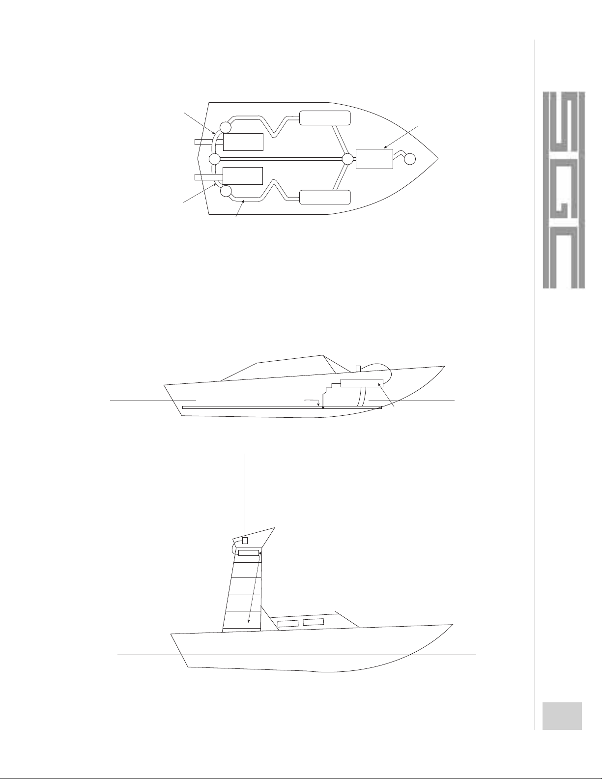
69
The SGC Building, 13737 S.E. 26th St. Bellevue, Washington 98005 USA
P.O. Box 3526, 98009 Tel: (425) 746-6310 Fax: (425) 746-6384
© 1997 SGC Inc.
FIBERGLASS HULL SPEEDBOAT
ENGINE
ENGINE
COUPLER
BOND METAL TANKS
WITH FOIL
GROUND
BONDING
GROUND
BONDING
GROUND
FOIL
2 - 3" WIDE
BOND METAL TANKS
WITH FOIL
POWER BOAT
COPPER FOIL COUNTERPOISE
COPPER
FOIL
SG – 230
COUPLER
SG – 303 9FT. WHIP
OR
SG – 203 28FT. WHIP
ANTENNA
ANTENNA
SG – 230
COUPLER
METAL
FISH
TOWER
SMALL BOAT WITH
FISHING TOWER
Page 72

70
The SGC Building, 13737 S.E. 26th St. Bellevue, Washington 98005 USA
P.O. Box 3526, 98009 Tel: (425) 746-6310 Fax: (425) 746-6384
© 1997 SGC Inc.
Like boats, aircraft fuselages are covered in various materials, conductive or nonconductive. As a result, you
will need to choose your ground location carefully. If the skeleton of the plane is aluminum and seems to be
electrically bonded throughout, attach the ground strap to the aluminum. As in any mobile radio installation, be sure
to wire brush the surface of the metal before attaching the ground strap. Likewise, after you have attached the
ground strap, spray a light coat of weather-resistant spray paint over the area.
Even if your ground connections are not in a location where they are in extreme weather, they should be
checked occasionally. All mechanical joints should be very tight or they will corrode under the presence of oxygen
and moisture. This light tarnish or rust will isolate the connection from the ground and ruin the system. In addition
to covering joints with a light coat of spray paint, it's a good idea to entirely encase the joint in a few globs of
silicone bathtub caulking that you can apply with your finger. For long, thin connections, such as wires, wrap
the connections very tightly with electrical tape, then cover the electrical tape with a light coating of silicone
bathtub caulking.
Ground systems which corrode due to natural age may be repaired on a periodic
basis. Outdoor conditions can be destructive to ground connections, but the worst-case
scenario is on marine vessels in salt water. As a result, you should check out the
connections every six months and if you have any question about their integrity, scrape off the caulking, unscrew the
bolt, wire brush the metal, and do it all over again.
Another problem with marine grounds (especially) is electrolysis. In this type of electrolysis, electricity is
flowing through a metal conductor and the water surrounding the conductor breaks down into oxygen and hydrogen.
As this process is occurring, the metals are also slowly being eaten away. As a result, you should check the metals in
the grounds to make sure that everything is working properly.
The radial ground systems at base stations are perhaps the most difficult systems to keep up regular maintenance on. Fortunately, base station grounds will usually last for a number of years--perhaps several decades. Even
so, you should regularly check the connection at the base of the radial system (where all of the radials connect to the
copper ground pipe). If this connection goes, all of those buried ground radials are virtually useless.
AIRCRAFT GROUNDS
GROUND DAMAGE, AGEING AND MAINTENANCE
Periodically check
ground connections for
corrosion or aging.
Page 73

The SGC Building, 13737 S.E. 26th St. Bellevue, Washington 98005 USA
P.O. Box 3526, 98009 Tel: (206) 746-6310 Fax: (425) 746-6384
© 1997 SGC Inc.
71
INSTALLATION
CHAPTER 4
Page 74

72
The SGC Building, 13737 S.E. 26th St. Bellevue, Washington 98005 USA
P.O. Box 3526, 98009 Tel: (425) 746-6310 Fax: (425) 746-6384
© 1997 SGC Inc.
The installation of any radio shack or portable system is of utmost importance. Of course, everything seems as
though it's of utmost importance with HF radio systems! In all of the other cases, it's been for technical or practical
reasons that something was done in a particular manner. In the case of setting up the shack or mobile installation, it's
all convenience. If the equipment is installed such a way that it is inconvenient for you to operate it, chances are that
you won't. If you don't use your HF equipment, you could miss out on the fun of operating an amateur station, your
organization could miss out on the benefits of utilizing the full benefits of this communications medium, or you
could put yourself in danger by being uninformed.
For a base-station installation, determining the location for your transceiver is simple. Just find a comfortable
work area (such as on a large desk or table) and sit it there. For any other type of installation, you are bound to find
yourself working against small space, an uncomfortable mounting location, and potentially harsh conditions. Then
it's time to get creative.
INSTALLATION
TRANSCEIVER
BASE STATION INSTALLATION
WINDOW
ANTENNA
METAL POST
BRACKET
RADIO
12 VOLTS POWER SUPPLY
SGC MODEL PS-30
COUPLER CABLE
COUPLER
GROUND RADIALS LONGER
THAN ANTENNA LENGTH
ISOLATOR
Page 75

73
The SGC Building, 13737 S.E. 26th St. Bellevue, Washington 98005 USA
P.O. Box 3526, 98009 Tel: (425) 746-6310 Fax: (425) 746-6384
© 1997 SGC Inc.
For most vehicular locations, it is best to mount the transceiver in the dashboard or just under the dashboard (or
control panel). This way, all of the controls are right in front of you; if you are driving or
flying, you will be able to easily operate the transceiver from the driver's seat. If more
people are on board and more concentration needs to be put into radio operations, the radio
can be operated by someone in the front seat beside the driver.
Because different types of transceivers are used in so many different applications, it is
difficult to make recommendations on how they should be installed. However, it is often most practical to mount
the equipment under the dash or control panel by merely screwing in the mounting plate. If there is any question as
to the number of bumps and jolts that the radio will receive while installed in that location, use a shock mount.
Shock mounts aren't always recommended, but it is better to play it safe with your communications equipment,
especially in large helicopters or tugboats.
If you are installing a transceiver, such as the SG-2000, in
a marine or car operating environment, you might want to take
advantage of the remote head technology of the radio. With
the remote head, you can place the SG-2000 in an out-of-theway location (right next to your DC power source,whether it is
an AC/DC power supply or your battery system) and set up the
much smaller remote head somewhere else. That allows you to
have the extra space to operate from a small, but convenient
location. When mounting the control
head in this manner, use the remote head kit's gimbal mount. This mount allows you to
change the control head angle to prevent glare on the display screen. Also, because the
mount is adjustable, other operators can change the angle to their liking.
Running power cables As inconvenient as it might seem, whenever you operate a
piece of electrical equipment, the power must come from somewhere, and power cables must be installed. With any
transceiver, the power cables must be kept as short as possible. No wire or cable is 100% efficient and the longer
that your cable is, the more power will be lost. As a result, if the power cable is too long, the transceiver will
operate with less-than-optimum amounts of power. Also, the longer the power cables are, the better the chance that
something could go wrong along the way (shorts, opens, etc.). SGC recommends that you use runs of less than 25
feet for your transceiver power cables; in any case, you should try to keep the cables as short as possible.
In addition to the specifications for the cable length, the cable gauge is also very important. If more power is
running through the cable than it can accommodate, then it will overheat or simply prevent the transceiver from
With any HF
transceiver, the
power cables must
be kept as short
as possible.
For most vehicular
locations, it is best
to mount the
transceiver in the
dashboard or
control panel.
Page 76

running at its full capability when transmitting. SGC recommends using #6 gauge stranded
copper cable for power runs on 12-volt operation for the SG-2000. Some smaller gauges
might work satisfactorily, but it's best to be safe and keep the installation as solid as
possible--especially when it only involves a small additional cost for cable.
Connecting the ground The ground connector on the SG-2000 is simply a non-insulated ring terminal
screwed onto a bolt. Remove the nut and the ring terminal. Run the ground wire or ground strap into the end
of the ring terminal. Crimp it in place with a pair of pliers, then solder it, to make a good physical and
electrical connection.
Connecting the feedline The SG-2000
uses a standard SO-239 connector for its RF
input/output. Simply stick the end of the PL-259
plug (of the antenna feedline) in the SO-239 and
screw the sleeve in place until it is tight. The
connection is only electrical, so just tighten the
connection with your hand, don't use any tools!
Connecting the audio I/O jack
assembly
On the SG-2000, the audio I/O,
ground, and external PTT line are all contained on
one jack assembly. The audio I/O means different
things to different people, but in this case, it is
intended for digital communications: to connect a
modem, for weather fax, or for Telerex
TM
. This
connector can also be used for some other functions, such as a key jack for Morse code (CW) operation. Just make
sure that you have the mating connector soldered to the appropriate wires (refer to the SG-2000 manual for pin out
information). Plug it in and you're ready to roll.
74
The SGC Building, 13737 S.E. 26th St. Bellevue, Washington 98005 USA
P.O. Box 3526, 98009 Tel: (425) 746-6310 Fax: (425) 746-6384
© 1997 SGC Inc.
Use #6 gauge
stranded copper
cable for power
runs on 12-volt
HF systems.
CONNECTING AND CONNECTOR TYPES
J-301
123
EXTERNAL MODEM,
WEATHERFAX AND HIGH
SEAS DIRECT
TM
4
AUDIOINGND
AUDIO
OUT
PTT
Page 77

75
The SGC Building, 13737 S.E. 26th St. Bellevue, Washington 98005 USA
P.O. Box 3526, 98009 Tel: (425) 746-6310 Fax: (425) 746-6384
© 1997 SGC Inc.
The remote control head can easily be connected to the 10-pin connector located on the back panel of the
SG-2000. The remote control is connected to the main unit via a 10-wire control cable. This cable is with wire
and not fiberoptic cable so that it can quickly be field repaired if it becomes damaged. If more than one remote
control head is used, then a junction box can be plugged into the 10-pin socket. This junction box can accommodate
the connection of up to eight more remote control heads. For information on installing the remote control head kits,
see the SG-2000 manual.
CONNECTING THE REMOTE CONTROL
SG 2000
REAR PANEL
J503
JUNCTION BOX
FOR ADDITIONAL
CONTROL HEADS
SINGLE CONTROL HEAD
REAR PANEL CONNECTION FOR ADDITIONAL CONTROL H
1 2 3 4 5 6 7 8 9 10
J503
Page 78

76
The SGC Building, 13737 S.E. 26th St. Bellevue, Washington 98005 USA
P.O. Box 3526, 98009 Tel: (425) 746-6310 Fax: (425) 746-6384
© 1997 SGC Inc.
An antenna coupler must always be located at the base of the antenna, and usually
they are mounted inside of the radio-operating area of a vehicle or in the radio room. With
the SG-230 Smartuner™, you can mount this system in either an indoor or an outdoor
location. Antenna couplers are placed at the antenna and they match the conditions of the
antenna to the feedline in a very precise manner. Antenna tuner trimmers, on the other
hand, are generally located at the transmitter output at the radio end of the coaxial feedline. Don't confuse these
terms. Antenna tuner trimmers placed at the transmitter allow substantial losses in feedlines to be corrected in order
to fool a transmitter into working correctly. The losses are dissipated through heat or to ground. A coupler installed
at the antenna eliminates these losses by providing a proper match from the antenna to the feedline.
The most important factor when installing the SG-230 antenna coupler is to make sure
that it is as close to the antenna as possible.
The further the coupler is mounted from the
antenna, the greater the transmitter signal
losses will be. Otherwise, the main concerns for the installation
location are simply that it is secure and out of the elements (if
possible). With the QMS (Quick Mounting System), you can mount
the SG-230 on the outside of a vehicle and it will be secure,
permanent or non-permanent, and able to resist the elements.
Connecting the power for the SG-230 is easy; just wire the + volts wire of the coupler to the +12-volts side of
the battery and wire the black ground wire to ground. It is best to use #8 stranded copper wire with weather-resistant
insulation for either indoor or outdoor use. Although you shouldn't operate a transceiver with long runs of power
cable, the SG-230 draws small amounts of current, so voltage dropping isn't a problem. As a result, you can mount
the Smartuner™ on an antenna tower and still rest at night, knowing that it is receiving the proper voltage. If the
SG-230 is operating from a marine, aircraft, or mobile location, just attach the power cables to the battery of the
COUPLER
Antenna couplers are
placed at the antenna
and precisely match the
conditions of the
antenna to the feedline.
The antenna coupler
should be mounted
as close to the
antenna as possible.
SG-230
SG-230
SG-230
H
F
B
LOCATION
CONNECTION TO POWER
Page 79

77
The SGC Building, 13737 S.E. 26th St. Bellevue, Washington 98005 USA
P.O. Box 3526, 98009 Tel: (425) 746-6310 Fax: (425) 746-6384
© 1997 SGC Inc.
system. If it is installed at a base site with AC power, either use a self-recharging battery-powered system (such as a
solar-charged battery) or connect the power terminals to a clean 12-volt bench power supply.
The SG-230 must be connected directly to the RF ground, which was covered earlier
in this user (Remember - the RF ground is the other half of your antenna). As was
described in that section, the connection between the ground cable and the ground (often a
bolt) must make a solid physical and electrical connection. Then it must be sealed with
spray paint or silicone bathroom caulking. Otherwise, one interesting and important rule is that your RF ground
must be larger (area-wise) than your antenna. This will probably occur naturally with base stations, but it can often
require quite a bit of work with mobile, marine, and airborne installations.
BLACK – GROUND
RED + 12 VDC
RED / WHITE – SMARTL
CONTROL LINE (option
BLACK / WHITE – REMO
TUNED INDICATOR
PL – 259
TO TRANSMITTER
SG – 230 SMARTUNER
(side view)
WIRE ANTENNA
DIAGRAM OF SMARTUNER INSTALLATION
LARGE GROUND (COUNTERPOISE) SYSTEM
9 FEET (2.8 METERS)
GROUND BOLT
ANTENNA OUTPUT
PORCELAIN
CONNECTORS
The SG-230
Smartuner must be
connected directly
to the RF ground.
CONNECTION TO RF GROUND
Page 80

78
The SGC Building, 13737 S.E. 26th St. Bellevue, Washington 98005 USA
P.O. Box 3526, 98009 Tel: (425) 746-6310 Fax: (425) 746-6384
© 1997 SGC Inc.
The SG-230 is merely connected to the transceiver via a piece of coaxial cable with a PL-259 connector on the
end. Just plug it in and screw on the sleeve and you're ready to go!
In most cases, the SG-230 will be connected to a simple wire antenna or to a vertical whip antenna. The single
"hot" wire must be plugged into the antenna jack of the coupler. No coaxial cable should ever be installed to the
antenna output jack of the SG-230. Always mount the antenna as high and far away from potentially interfering
objects (a truck cab, a steel building, under a steel bridge, etc.) as possible. Otherwise, the signal from the antenna
will be absorbed (to an extent) by the surrounding object and by the ground.
TO TRANSMITTER (10-50w)
BLACK: DC GROUND
RED: +12 VDC COUPLER POWER
RED/WHITE: OPTIONAL SMARTLOCK LOCK/RESET LINE. (+12 VDC LOCKS
MOMENTARILY GROUND RESETS
BLACK/WHITE: OPTIONAL REMOTE TUNED INDICATOR. GOES LOW WHEN
COUPLER IS TUNED.
ANTENNA
SINGLE WIRE
GROUND BOLT FOR COUNTERPOISE
PORCELAIN
ANTENNA
CONNECTOR
CONNECTION TO TRANSCEIVER
CONNECTION TO ANTENNA
Page 81

79
The SGC Building, 13737 S.E. 26th St. Bellevue, Washington 98005 USA
P.O. Box 3526, 98009 Tel: (425) 746-6310 Fax: (425) 746-6384
© 1997 SGC Inc.
The SG-230 is built solidly, so that it can used in a variety of environments. For marine operation, it is best for
the coupler to be located inside of the boat. On power boats, the coupler can be mounted outside, but an additional
protective housing is recommended. If the coupler is used in hot climates, it is best to install it inside of the QMS
(Quick Mounting System), which will help shield it from the sun. Likewise, if the SG-230 is to be mounted on a
tower, in either a hot or cold climate, it is best to turn a small plastic garbage can upside down and place it over the
coupler; then mount the system. The garbage can will insulate the coupler from the sun and will also prevent large
buildups of ice from forming.
Antennas have already been covered in this user guide, but their installation and what you can do to make them
work in the space that you have available have not. Like most every aspect of HF communications, good operations
generally require some materials, some work, and a great deal of creative technical designing.
LONGWIRE
SG – 230 SMARTUNER MOUNTED INSIDE A PLASTIC
WASTE BASKET TO PROTECT IT FROM EXTREME HEAT
AND HEAVY ICING. THIS TYPE OF ENCLOSURE IS
WIDELY AVAILABLE IN ALL COUNTRIES.
THE COUPLER IN A HARSH ENVIRONMENT
ANTENNA
Page 82

80
The SGC Building, 13737 S.E. 26th St. Bellevue, Washington 98005 USA
P.O. Box 3526, 98009 Tel: (425) 746-6310 Fax: (425) 746-6384
© 1997 SGC Inc.
As was mentioned in the previous section, it is of utmost importance to have your antenna as high above the
ground as possible, and as far away of any obstructions or contamination of appliance or industrial RF pollution
(such as power lines, telephone lines, mills or other industrial machinery). In some cases,
the ground will absorb quite a bit of the signal. A few examples of this kind of ground
absorption are when an antenna, such as a dipole or a longwire, is located near the
ground. "Near the ground" means that any distance less than a half wavelength above the
ground will skew the signal pattern and absorb a certain amount of the signal.
Considering that a half wavelength for the 40-meter amateur band would be 66 feet off the ground and a half
wavelength for the 80-meter amateur band would be 122 feet off the ground, it will often be impossible for you to
mount an antenna at such a height. Thus, the "as high as possible" rule is used.
Mobile and portable mounting locations are even more difficult to to deal with
because physical objects also absorb RF signals. As a result, your antenna has to contend
with ground losses and signal absorption because the antenna is near the ground. The last
thing you want to do is have your signals absorbed by a part of the vehicle. The best
Always mount the
antenna as high as
possible, and away
from obstructions and
interfering objects.
LOCATION
The best vehicle
antenna location is
on the roof or trunk.
POOR
ANTENNA
LOCATION
POOR
ANTENNA
LOCATION
POOR
ANTENNA
LOCATION
WRONG VEHICULAR
INSTALLATION
Page 83

antenna mounting locations for a vertical whip on a vehicle are on the roof or on the trunk. If you mount the whip
antenna on one of the bumpers or in the bed of a pickup, much of the antenna length will be below the height of the
vehicle. Then a lot of the signal will get sucked down by all of that steel.
You have to get power from the transceiver to the antenna. To do this, you need a transmission line. As stated
previously, use a high quality RG8, RG8X or RG58 coaxial cable with at least a 95% outer braid.
This is a very critical issue because at the base of the antenna high voltages (up to 10,000 volts) can develop.
The feedthrough hole must withstand this high voltage. Generally, a high voltage porcelain feed connector, which
is very common in the marine industry, is used. For a vehicular installation, the only way to go about this properly
is to make a large (2 inch in diameter) hole with a fiberglass plughole. The wire will go through the center, with the
minimum distances between the metal structure and the wire at least 1.5 inches.
The feedline has a few peculiar relationships with the antenna elements. In the case of most antennas, the
feedline should be run perpendicularly to the antenna element. In most mobile or
portable installations, the feedline is short and it runs either perpendicular to the
antenna or up to the antenna, so there is no problem.
Obviously, if the feedline at a base station should be run perpendicularly to a
horizontal antenna, you can have some real problems with running the feedline in a safe and appropriate location.
Fortunately, unlike unbalanced ladder line feedline, coaxial cable can be run along buildings and along or even
under the ground. This makes feedline runs much more convenient. Also, the feedline doesn't have to run
perpendicularly for its entire length; it's just best to have the last quarter wavelength (as compared to the operating
frequency of the antenna) run this way.
81
The SGC Building, 13737 S.E. 26th St. Bellevue, Washington 98005 USA
P.O. Box 3526, 98009 Tel: (425) 746-6310 Fax: (425) 746-6384
© 1997 SGC Inc.
FEEDLINES
FEEDTHROUGH CONNECTORS OR HOLES
FEEDLINE ROUTING
In most cases, the
feedline should be run
perpendicularly to the
antenna element.
Page 84

82
The SGC Building, 13737 S.E. 26th St. Bellevue, Washington 98005 USA
P.O. Box 3526, 98009 Tel: (425) 746-6310 Fax: (425) 746-6384
© 1997 SGC Inc.
Because most antennas are located outdoors, they will be subjected to harsh weather.
You don't have to worry about this if you are using SGC antennas because they are built to
last in harsh environments. If you are building your own antennas, be sure to use strong
materials, solder and connect them soundly, and waterproof them. All solder connections
should be electrically and physically solid. Then cover them with silicone bathtub caulking,
tape them tightly with electrical tape, and smear more caulking overtop. If you are installing
a long-term antenna, you don't want the joints to break down after only six months or a year in the air.
Noise and interference are the worst problems with HF communications. Because the radio signals can travel
thousands of miles around the world, the sources of noise can also travel great distances and plague HF users. In the
early days of radio, the users of the HF (and lower) frequencies found that the radio spectrum was filled with static
and thunderstorm crashes. In today's industrial and electronics-based world, those natural noises have been joined
by countless forms of man-made interference. There is little that you can do to avoid the natural interference, but
dodging the man-made interference is a fine science. The simplest rule is to stay away from houses or buildings.
Natural interference is caused by such things as solar activity and thunderstorms.
The worst form of natural interference is caused by lightning. The radio signals from the massive bolts of
electricity can easily propagate for hundreds of miles and cause what are typically known as static crashes across the
HF spectrum. Aside from avoiding operations during local thunderstorms, there is little that you can do to avoid this
interference. Snow and rain also create static that will cause communications problems.
HARSH ENVIRONMENTS
NOISE AND INTERFERENCE
All solder
connections should
be electrically and
physically solid,
and protected by
silicone sealant.
NATURAL INTERFERENCE
Page 85

Man-made interference is emanated from most any location where electrical appliances are being used.
However, the worst causes of interference are caused by neon signs, fluorescent lights,
arc welders, faulty televisions, motors and engines, and faulty power-line transformers.
If you can choose the location for your radio installation, you are much better off setting
up in a rural area--chances are that there will be a relatively small amount of man-made
interference. For base-station operation, you should not operate fluorescent lights.
Otherwise, there is little that you can do to persuade local businesses to remove their
neon advertising signs or change back to incandescent lighting.
For mobile operations, you are stuck in a noisy environment. The ignition system, engine, alternator, electrical
system, and wheels all produce electrical noise. Severe noise from the ignition system is caused by the sparks of
electricity at the spark plugs. If you have a diesel car or truck, which has no spark plugs, you are spared from this
noise. But the engine and alternator both produce noise from the cycling metal (the pumping cylinders in the engine
and the spinning coil of wire in the alternator). Electrical signals from passing wires (such as for the turn signals,
etc.) can sometimes interfere with a nearby HF radio. The last form of vehicular HF interference occurs when
driving; the tires roll on the pavement (both nonconductors) at high speeds and build up static electricity.
83
The SGC Building, 13737 S.E. 26th St. Bellevue, Washington 98005 USA
P.O. Box 3526, 98009 Tel: (425) 746-6310 Fax: (425) 746-6384
© 1997 SGC Inc.
MAN-MADE INTERFERENCE
Man-made interference:
neon signs, fluorescent
lights, faulty
televisions, electric
motors, engines, faulty
power line
transformers, etc.
Page 86

84
The SGC Building, 13737 S.E. 26th St. Bellevue, Washington 98005 USA
P.O. Box 3526, 98009 Tel: (425) 746-6310 Fax: (425) 746-6384
© 1997 SGC Inc.
Even though you might be stuck in a location where man-made noise is abundant, you don't have to be bothered
by this interference. A number of different techniques can eliminate some or all of the noise at the source, or by
filtering or changing that noise.
DSP is one of the new audio technologies that is just starting to take off. With DSP technology, the radio audio
is turned into digital signals and certain patterns, such as noise patterns, can be filtered out. In some cases, it might
even be possible for the audio signal to be partially reconstructed. It won't be long until DSP technology is contained
in most every radio. Just as digital frequency readout boxes were available for every transceiver 25 years ago,
separate DSP boxes will soon look archaic and it will be assumed that the technology will be in every radio 25 years
from now.
The noise blanker is a circuit that is effective in limiting quick, "pops" in the audio. When a loud, quick noise
occurs, the noise blanker turns the audio circuit off for a very brief amount of time. The circuit is turned off and on
so quickly that you don't even realize that it happened. Noise blankers only work with brief "pops;" if a noise
blanker is used with a constant noise source, the audio will be reduced and effect will be similar to using an
attenuator.
Magnetic antennas have nothing to do with car whip "mag mounts" or a tacky antenna that you could stick on
your refrigerator. These antennas are all types of loop antennas, which receive the magnetic component of radio
waves and not the voltage component. As a result, although the received signals are at a lower level, the interference
is also greatly reduced.
DIGITAL SIGNAL PROCESSING (DSP)
NOISE BLANKER
MAGNETIC ANTENNAS
NOISE REMEDIES AT THE TRANSCEIVER
Page 87

85
The SGC Building, 13737 S.E. 26th St. Bellevue, Washington 98005 USA
P.O. Box 3526, 98009 Tel: (425) 746-6310 Fax: (425) 746-6384
© 1997 SGC Inc.
If you can't beat it, avoid it. Some types of interference are centered around particular frequencies or bands.
For example, fluorescent light noise is often worst at the lower frequencies. If you can move up into the 10 MHz
(and above) region, this type of interference will often drop significantly. Of course, these types of interference can
vary, so you will have to check the bands and determine which frequencies are best. Of course, your ability to
change frequencies will depend on what frequencies you are allocated to operate on.
In vehicles with traditional gas-fueled engines, ignition noise is one of the most damaging forms of
interference. Without some sort of ignition noise suppression, it will be difficult to receive, and thus to make any
contacts on the HF bands.
Quite a bit of engine noise can be eliminated if various parts of the vehicle are isolated and bypassed. Just
purchase some 0.01- to 0.1-microfarad 100-volt ceramic disk capacitors from an electronics parts house (such as
Radio Shack). Then install one capacitor inline with each lead from the battery and from the alternator. Make sure
that all solder joints are solid, clean, and sealed. If the ignition system is noisy, add a
capacitor in line with the primary side of the ignition. Don't put capacitors in any other
location around the ignition or you might reduce and delay the voltage to the ignition. If this
is the case, you will have countered the effect of the ignition and the car might not work!
Another method to reduce noise is to place resistance in line with the spark plugs. The resistances can be added
near the spark plugs, in ignition cable, or in the spark plugs themselves. When resistors are added near the spark
plugs, they are often installed at the distributor towers or spark plug terminals, moulded into the distributor rotor,
towers, or the center contact button.
The most commonly used ignition noise suppressor is resistance ignition cable. This cable is available in either
low-resistance types (3000 to 7000 ohms) or high-resistance types (6000 to 12000 ohms).
The last method is to use noise-suppressing "resistor" spark plugs. These special spark plugs contain resistance
elements to reduce radio-frequency radiation from the ignition coil and to virtually eliminate the high-frequency
part of the spark.
CHANGE OF FREQUENCY
Engine noise can
be isolated and
bypassed.
ISOLATION AND BYPASSING
NOISE REMEDIES AT THE NOISE SOURCE
Page 88

86
The SGC Building, 13737 S.E. 26th St. Bellevue, Washington 98005 USA
P.O. Box 3526, 98009 Tel: (425) 746-6310 Fax: (425) 746-6384
© 1997 SGC Inc.
Although you can use resistor spark plugs with resistance ignition cable and with external suppressors, it is not
advisable to mix external resistance suppressors with resistance ignition cable. Also, do not use external resistors if
resistors are already built into the system.
Be sure to regularly check and repair (if necessary) the ignition system in your vehicle if you are using a
transceiver inside. Suppressor cables can be damaged if you handle them roughly, and they can simply deteriorate
with age. Occasionally check the connections and be sure to pull the connectors off carefully. If the connectors are
damaged, it is usually much more effective to purchase a new suppressor cable than to repair one.
Replace any parts in the electrical system that are worn or corroded at the connections. Replace the distributor
cap and rotor if the rotor tip and the contacts inside of the cap are wearing down. If the connections in the ignition
system are worn, severe interference could result. If a miniscule (a fraction of a millimeter) gap is created in this
system, the electricity will have to jump the space, and will radiate (radio interference). These miniscule gaps can be
created by loose connections or by dirty connections. Be sure to check them and replace them if necessary.
Bonding was covered earlier in the section with grounds for marine installations. It
involves using large chunks of copper foil (or possible other materials to interconnect
all large pieces of metal to form the ground. Bonding will prevent the possibility of
having ground loops (which cause noise when receiving) in your system. Ground loops
occur when two or more components are connected to different "grounds" that are not at
the same potential. In a more general sense, bonding is the process of linking the components of any ground. When
bonding the ground in a vehicle, use ground straps, lockwashers, and self-tapping screws to bond different parts of
the car together.
You can cure front-wheel static and "pops" by installing static collector rings inside of the front wheel caps.
Automobile static buildup can also be bled-off by attaching an automotive ground strap to the car frame and
having it drag along the pavement. Almost any auto parts store will have these ground straps.
Ground loops occur when
two or more components
are connected to different
"grounds" that are not at
the same potential.
BONDING
STATIC COLLECTORS
Page 89

Shielding typically involves using metal to prevent noise signals from entering your radio. This could mean
using a metal cabinet (instead of a plastic cabinet) or using coaxial cable (instead of ladder line feedline). With
having an inboard engine in a boat with a nonmetallic hull, it means shielding the engine. To do so, you must shield
the entire engine compartment with copper or bronze screening.
If the system is grounded, the typical "ground hum" should not plague your radio. See the section on
grounding for more information on installing a good ground.
Even if you can't eliminate all of your noise problems, you might be able to avoid them by moving your
antenna. On a vehicle, you should move the antenna as far from the engine compartment as
possible. In a base location, it could mean moving the antenna from the front yard to the
back to keep it from being nearby and parallel to noise-producing power lines.
87
The SGC Building, 13737 S.E. 26th St. Bellevue, Washington 98005 USA
P.O. Box 3526, 98009 Tel: (425) 746-6310 Fax: (425) 746-6384
© 1997 SGC Inc.
Sometimes, simply
moving the antenna
reduces noise.
SHIELDING
GROUNDING
MOVING THE ANTENNA
Page 90

88
The SGC Building, 13737 S.E. 26th St. Bellevue, Washington 98005 USA
P.O. Box 3526, 98009 Tel: (425) 746-6310 Fax: (425) 746-6384
© 1997 SGC Inc.
The power is typically the output of the transceiver in watts. Power could be measured in a number of different
ways, but output power is the most common and most practical method. The power is measured on a wattmeter,
which is connected between the transceiver and the antenna. Some antenna tuners have built-in wattmeters so that
you can determine the output power.
The forward power is the amount of power (in watts) that is actually emanating from
your antenna. The forward power is the output power minus the wattage that is lost in the
SWR and through the feedline. The forward power can be measured with a wattmeter.
12 VOLT POWER SOURCE
SETUP FOR ELECTRICAL CHECK OUT:
SG–2000 HF RADIO
BACK OF UNIT
WATT METER
SG–230
ANTENNA
COUNTERPOISE
TERMINAL
BLOCK FOR DC
POWER CABLE
FORWARD POWER
POWER CONCEPTS
Forward Power is the
amount of power
actually emanating
from the antenna.
Page 91

89
The SGC Building, 13737 S.E. 26th St. Bellevue, Washington 98005 USA
P.O. Box 3526, 98009 Tel: (425) 746-6310 Fax: (425) 746-6384
© 1997 SGC Inc.
The reflected power is the amount of power (in watts) that is reflected back from the antenna (in the form of
standing waves). This power is reflected back to the transmitter as a result of antenna
mismatch. The lower the reflected power, the better; this power eventually becomes
dissipated by the output section of the transmitter, and it could damage it. The reflected
power can be calculated with a reflection meter.
Standing waves are waves of RF signal that are reflected back to the transmitter as a result of an impedance
mismatch. The reflected power is a measurement of the amount of power that is wasted in standing waves.
Likewise, the VSWR is the ratio of standing waves in a radio transmitting system.
The VSWR rating represents the voltage standing wave ratio in a system. The ratio
represented is actually either the ratio of the maximum voltage to the minimum voltage or
the maximum current to the minimum current. For most people, this isn't important. What is
important is that you need to keep the ratio as low (close to 1:1) as possible. A VSWR
(usually known as SWR) of more than 3:1 is too high and you either need an antenna coupler or (if you don't have
one) you need to trim your antenna to the correct (resonant) length. The SWR is typically measured on an SWR
meter, although this function is sometimes built into transceivers and antenna tuners.
The field strength is the measure of a radio signal as it is being transmitted from the antenna. The field
strength is usually determined in microvolts per meter away from the antenna. To measure this voltage, you must
use a field-strength meter.
Reflected Power is the
amount of power
reflected back from
the antenna.
REFLECTED POWER
STANDING WAVES
VSWR should
always be kept as
low as possible.
VSWR
FIELD STRENGTH
Page 92

90
The SGC Building, 13737 S.E. 26th St. Bellevue, Washington 98005 USA
P.O. Box 3526, 98009 Tel: (425) 746-6310 Fax: (425) 746-6384
© 1997 SGC Inc.
As described very early in this user guide, the frequency is the number of radio waves
that pass by a given point in a second. The frequency is "where you are" on the radio. It
also determines how far your signal can travel and when it can travel the furthest. It is very
important to have an accurate digital frequency readout on a transceiver or your signal
could stray into areas where it is not authorized and cause potentially dangerous interference. The frequencies of
various transceivers and other equipment are determined with a frequency counter.
Gain and levels describes a number of different aspects of radio. Gain describes an
increase in a signal, whether current, voltage, or power. On a transceiver, the gain control
is what controls the volume. In an amplifier, the gain would be
the improved output signal (in dB) over what was input to the amplifier. With an antenna,
the gain is the improvement in signal strength (in dB) over a reference antenna (usually
an omni-directional antenna or a half-wave dipole).
The level of a signal usually refers to how loud it is. As a result, the levels of a received signal are usually
measured on an S-meter (see the next section) or on a linear LED meter.
Any time that a transmitter is used, it must be outputting into a load. A load is anything that the output power
can be pumped into. If the transmitter is operated without any sort of load connected, the final amplifier stage could
become severely damaged. The problem is that you should never test a transmitter on the air for the first time, if you
are unsure about how to operate it, and if you are unsure whether it is working properly. You could create harmful
interference to other stations.
To test transmitters without actually operating into an antenna, dummy loads were created. A dummy load is a
load that will dissipate the energy from the transmitter instead of emanating it into the ionosphere. Nearly all
commercial dummy loads are large oil-filled cans. These dummy loads change the transmitted energy into heat,
which is absorbed by the oil. Because different transmitters output different amounts of power, different sizes of
dummy loads must be used. Dummy loads for typical amateur powers (under 500 watts) are relatively inexpensive
and are readily available.
FREQUENCY
An accurate Digital
Frequency Readout
is an essential HF
transceiver feature.
GAINS AND LEVELS
dB Gain describes an
increase in signal level.
Level refers to how
loud the signal is.
DO-IT-YOURSELF LIGHT-BULB DUMMY LOAD
Page 93

91
The SGC Building, 13737 S.E. 26th St. Bellevue, Washington 98005 USA
P.O. Box 3526, 98009 Tel: (425) 746-6310 Fax: (425) 746-6384
© 1997 SGC Inc.
Unfortunately, when you use a can-type dummy load, you can't see "what's happening" with your transmitter.
In this case, you can use a light-bulb dummy load to test your transmitter. Here, the light bulb is directly connected
to the output of the transmitter and it dissipates the RF energy as light. The light bulb dummy load is more useful
than the oil-can type because you can guess how much power is being output, you can see the voice modulate the
SSB (the light will flicker with your voice peaks), and you can tune the transmitter for maximum output (if the
transmitter is an older model that requires tuning).
Before building or using the light-bulb dummy load, remember that these models typically don't dissipate the
transmitter's output as well as an oil-can dummy load. The result is that RF will "leak" out; I have heard a few
stories of amateurs who were heard around town while operating their transmitters into a light-bulb dummy load. If
you use this system, make sure that you test the equipment on a clear, harmless frequency (NEVER test with the
transmitter set on an emergency frequency, such as 2182 kHz).
SGC recommends that you build the light-bulb dummy load with the following parts (although I have made
one with an old light fixture and a makeshift version with just alligator clip leads and a light bulb):
* AC socket to cable with a PL-259 connector
* AC socket to cable with alligator clips (needed with coupler)
* Light bulb to AC adapter
* 75 to 125 watt light bulb, 120 to 220 VAC
* SG-2000 transceiver
* SG-230 coupler (optional)
RF IN-OUT
RF GND
SG-2000 RADIO
Page 94

RF IN-OUT
RF GND
SG-2000 RADIO SG-230 ANTENNA COUPLER
ANTENNA JACK
GND
92
The SGC Building, 13737 S.E. 26th St. Bellevue, Washington 98005 USA
P.O. Box 3526, 98009 Tel: (425) 746-6310 Fax: (425) 746-6384
© 1997 SGC Inc.
1. Connect the transceiver dummy load to the SG-2000 RF in/out jack.
2. Turn on the radio, set the CW mode, and set the power to HI.
3. Key the PTT switch on the microphone and look at the light bulb. If the dummy load is connected and the radio
is transmitting, the light should turn on.
4. Set the power to LO.
5. Key the PTT switch on the microphone and look at the light bulb. If the dummy load is connected and the
radio is transmitting, the light should turn on. Notice that the light is not as bright as in step 3 (the power
switch is setto LO).
6. Set the power to HI.
7. Set the SG-2000 mode to A3H.
8. Key the PTT switch on the microphone and look at the light bulb. The light should come on if the radio is
transmitting. Notice that the light is not as bright as in step 3.
9. Set the SG-2000 to A3J mode.
10. Key the PTT switch on the microphone and talk into the microphone. Notice that the light turns on
when you talk.
11. Set the SG-2000 to the A3A mode.
12. Key the PTT switch on the microphone and talk into the microphone. Notice that the light bulb comes on
when you talk.
RADIO TEST PROCEDURE
Page 95

1. Connect the coupler to the SG-2000.
2. Connect the coupler dummy load to the SG-230 antenna jack.
3. Turn on the SG-2000 and the SG-230.
4. Set the SG-2000 to the CW mode.
5. Key the PTT switch on the microphone and look at the light bulb. The light should turn on if the coupler has
completed its' tuning cycle and if the radio is transmitting.
6. For further testing, follow steps 4 through 12 of the radio test procedure.
Note: The light bulb might not turn on immediately if the coupler has not yet been tuned for the frequency of the
transmitter. The output power (light-bulb brightness) is greatest when the coupler is properly tuned.
The wattmeter is a test instrument that can be connected in between the transceiver and the antenna to show
exactly how much power is being output by the transceiver.
The SWR meter is used to measure the standing-wave ratio of an antenna at a given frequency. If the
transceiver has a built-in SWR meter, it will automatically show the SWR. If the SWR meter is in a separate unit or
is contained in an antenna tuner, you might need to tweak a few knobs or settings to get the accurate SWR.
93
The SGC Building, 13737 S.E. 26th St. Bellevue, Washington 98005 USA
P.O. Box 3526, 98009 Tel: (425) 746-6310 Fax: (425) 746-6384
© 1997 SGC Inc.
COUPLER TEST PROCEDURE
INSTRUMENTS
WATTMETER
SWR METER
Page 96

94
The SGC Building, 13737 S.E. 26th St. Bellevue, Washington 98005 USA
P.O. Box 3526, 98009 Tel: (425) 746-6310 Fax: (425) 746-6384
© 1997 SGC Inc.
The field strength meter is a small handheld meter that is used to determine the strength of the signal (in
microvolts per meter) as it is being transmitted from the antenna. Field strength meters are typically very simple
radio circuits with a meter and a tuner.
The frequency counter is somewhat like a a field strength meter in the sense that
they are both handheld and contain radio circuits. With some frequency counters, you can
walk near an operating transmitter, push one button, and the exact frequency of the
transmission will be displayed. Frequency counters can be used to calibrate a transceiver.
If you don't have a frequency counter, you can exactly tune in to one of the WWV broadcasts(with the receiver in
SSB). You can then see how closely the receiver is on frequency.
An impedance bridge is used to determine the impedance of a circuit. An impedance can be handy when
operating an HF radio station because you can determine the impedance of an antenna that you are using and if you
need to match the system differently.
An S-meter shows the strength of the signal that is being received (in decibels).
The specifications for S-meters vary from one type of receiver to another, so the signal
ratings aren't terribly useful, except for your own personal use. As a result, some
newer receivers use a more linear system of LEDs or LCDs to show the signal rating (usually 0 to 10).
Frequency Counters can
be used to calibrate a
transceiver.
FIELD STRENGTH METER
FREQUENCY COUNTER
IMPEDANCE BRIDGE
An S-Meter shows the
strength of the signal
being received.
S-METER
Page 97

The SGC Building, 13737 S.E. 26th St. Bellevue, Washington 98005 USA
P.O. Box 3526, 98009 Tel: (425) 746-6310 Fax: (425) 746-6384
© 1997 SGC Inc.
95
AMATEUR RADIO
CHAPTER 5
Page 98

96
The SGC Building, 13737 S.E. 26th St. Bellevue, Washington 98005 USA
P.O. Box 3526, 98009 Tel: (425) 746-6310 Fax: (425) 746-6384
© 1997 SGC Inc.
Amateur radio is the private, personal way to experience HF communications as a hobby, rather than as a
profession.With amateur radio, you have the opportunity to talk with, send data to, or transmit pictures to thousands
of people around the world. In addition to the wonderful possibilities to communicate with and befriend others, the
potential to learn about a vast array of topics is amazing. All of this can occur while learning about HF radio,
electronics, and computers. In fact, many people become involved with amateur radio just for the opportunity to
participate in creative home construction and engineering projects. Amateur radio is truly the doorway to a
whole new world.
The first step to becoming an amateur radio operator is to get a license. This isn't the
CB band, where you can get a transceiver and hit the airwaves. Doing so (if you are
located in the United States) will certainly result in a visit or letter from the Federal
Communications Commission, which regulates radio activity in the U.S. The FCC agent
might also feel inclined to give you a Notice of Apparent Liability (NAL, basically a fine)
for as much as $100,000 for unlicensed radio operation.
In order to avoid a large fine and still experiment with the magic of HF radio, you must become licensed by the
FCC. The license process consists of two parts: the first consists of transmitting and receiving Morse code. The
second part is a written test that consists of a number of multiple-choice questions about radio theory.
Five different license classes exist for amateur radio on the HF bands: Novice, Technician, General, Advanced,
and Extra. Each of these licenses has more privileges and each is more difficult to achieve.
For example, with a Novice or Technician license, you are limited to operating in the CW
mode only, with reduced power, and only in certain segments of the amateur radio bands.
With a General license, you are able to operate with full amateur power (restricted to 1500
watts PEP output) and you are able to operate with any mode, but are restricted on some
frequencies. Advanced and Extra class tickets each allow the operator to use a few more
segments of frequency space. With an Extra class license, you can do everything that is
allowable with an amateur license. For more information on amateur radio licensing, check out the code practice
cassettes, license manuals, and beginners books on amateur radio from: the American Radio Relay League, 225
Main St. Newington, CT 06111.
AMATEUR RADIO
The first step in
becoming an amateur
radio operator is to
get a license.
A General License
allows you to use full
amateur power, in any
mode, but does not
allow use of every
amateur frequency.
Page 99

97
The SGC Building, 13737 S.E. 26th St. Bellevue, Washington 98005 USA
P.O. Box 3526, 98009 Tel: (425) 746-6310 Fax: (425) 746-6384
© 1997 SGC Inc.
THE U.S. HF AMATEUR BANDS
160 meters 1800 to 2000 kHz
80 meters 3500 to 4000 kHz
40 meters 7000 to 7300 kHz
30 meters 10100 to 10150 kHz (max. power 200 watts PEP output)
20 meters 14000 to 14350 kHz
17 meters 18068 to 18168 kHz
15 meters 21000 to 21450 kHz
12 meters 24890 to 24990 kHz
10 meters 28000 to 29700 kHz
The transmissions on the amateur bands all consist of two-way, noncommercial
communications. That means that you may not broadcast, cause willful interference to
other stations, or receive payment directly (or indirectly) for any communications. As
far as amateur radio is concerned, broadcasting occurs when music or entertainment is
aired for more than the one person that you are communicating with. Noncommercial communications means that
you can't make business calls or sell anything over the radio. It is also a violation of FCC rules to accept money for
communicating a message from someone to another operator. Profanity, as defined by the FCC, is also banned on
the amateur bands. If you are unsure about certain words, watch TV for a while to get a hang of what you can and
can't say on the air. A better guideline might be to consider what might offend someone else, then try to avoid those
words. It sure beats an FCC fine or the loss of your amateur license.
Aside from these points, you are free to talk about most anything that you please. These are the hobby aspects
of amateur radio. You can get on the air, call someone, and have a conversation. To make things more interesting,
many amateurs have established little networks for a variety of reasons. A network is an established group that
meets at a particular time every day, week, or month. The group is run by a net control, who mediates the
discussions. Then everyone can participate in a round-robin discussion. The nets cover a huge variety of topics,
although most are informational and not nearly as rude or controversial as some of the Usenet groups on the
Internet. Because of these amateur radio nets and because of shortwave broadcasting, HF/shortwave is sometimes
called the original information highway. For more information on amateur radio operations, see The ARRL
Operating Manual, which is a massive tome that covers most every aspect of amateur radio operations.
Transmission on amateur
bands all consist of two-
way, non-commercial
communications.
AMATEUR OPERATIONS
Page 100

98
The SGC Building, 13737 S.E. 26th St. Bellevue, Washington 98005 USA
P.O. Box 3526, 98009 Tel: (425) 746-6310 Fax: (425) 746-6384
© 1997 SGC Inc.
This user guide has covered many aspects of HF communications, so this section on the communications
potential of amateur radio covers primarily old material. The SG-2000 has an output power of 150 watts PEP, so it
does not even approach the amateur legal limit. However, most amateur transceivers only have 100 watts (or less) of
output power, and they are intended to be operated with a station amplifier.
The standard 100-watt power level of most transceivers is plenty in most situations. The 150 watts from the
SG-2000 gives you a bit extra power if you need it; if you don't, you can reduce the power to 50 watts. With 150
watts, signals on the frequencies below 5000 kHz are generally regional: restricted to a daytime range of several
hundred miles and a nighttime range of 1000 to 2000 miles. Between 5000 and 10000 kHz, you could expect a
range of 500 to 1000 miles during the daylight hours and 2000 to 4000 miles at nighttime. From 10000 to 15000
kHz, you can expect a range of 1000 to 4000 miles during the daytime and the same range for part of the nighttime
hours. From 15000 to 30000 MHz, the range is from 1000 to 4000 miles, but the range is virtually unusable at night.
With the SG-2000, a good ground, and a good antenna, you should be able to regularly
contact other amateurs around the block or around the world. However, if you need to
regularly communicate with many stations in distant, remote locations, you might consider
using a high-quality amplifier. One of the sturdiest amateur power amplifiers on the market
today is the SG-500 Smart PowerCube. This amplifier is fully automatic and is rated to
continuously output 500 watts PEP.
The U.S. FCC issues licenses for the operation of many classes of radio stations. This includes ham radio
stations, commercial marine shore stations, shipboard stations and those that involve kinds of mobile applications
(such as systems aboard aircraft). There is an exception. Stations operating under the auspices of the U.S. military
and stations in the Military Affiliate Radio System (MARS), are exempt from the licensing requirements of the
FCC, but are subject to military rules. Most countries have similar regulations.
Boat owners must meet a number of licensing requirements before lawfully
transmitting any radiotelephone messages. According to FCC regulations, the following
must be on board the vessel: 1. a valid ship radiotelephone station license, 2. a valid
radiotelephone operator license, and 3. a radio station logbook.
Anyone who uses the radiotelephone should be thoroughly familiar with approved
communication procedures and operating features of the equipment. Although anyone can use the radiotelephone,
an operator holding a Restricted Radiotelephone Permit must be on board when any transmissions are made. This
operator is responsible for the radio emissions whenever the radio is used. No examination is required to obtain this
license. This operator's permit does not authorize adjustments to the transmitter, and all tuning adjustments to any
Boatowners must have
a Vessel Marine License
and a VHF License
before lawfully
transmitting any HF
marine frequencies.
COMMERCIAL LICENSING
With an SG-2000,
a good ground,
and a good
antenna, you can
contact amateurs
around the block
or around
 Loading...