

Page 1
Page 2

SGC – The SSB People
SGC develops, manufactures, and sells high performance single sideband (SSB)
communications equipment. For more than 25 years, the company has sold to the
marine, military, aviation, and industrial markets world wide. Over these years,
SGC has earned an outstanding reputation for product reliability and for service
after sale.
On the cutting edge of technology, the company keeps pace with equipment
options, engineering developments, and design requirements. Its products are the
most competitive in the entire long distance communication market. SGC equipment is presently being used by the United Nations and international relief agencies
for inter-communications in developing countries throughout the world. Many
competitive racing vessels, as well as fishing boats, tugs, and commercial craft are
equipped with SGc equipment. In fact, an SGC radiotelephone provided the only
communication available on a recent Polar expedition by the National Geographic
Society.
SGC supplies U.S. Government agencies, foreign governmental agencies, and
major petroleum companies throughout Asia and Latin America. In addition, SGC
supplies equipment to major international geophysical corporations and exploration
crews.
All SGC equipment is designed and manufactured in the USA, with some components imported for different international suppliers and manufacturers. SGC has
qualified people ready to provide technical information, assistance in selecting
equipment, and recommendations for installations.
SGC welcomes your call to discuss your HF-SSB requirements.
Page 3

Digital Signal
Processing
Facts and Equipment
Another
Informative Publication of
SGC, Inc.
Manufacturer of Advanced
Technology
ÒNo Compromise CommunicationsÓ
Page 4

Table of Contents
Chapter 1
The idea of Digital Sound Processing 1
Understanding Sound 1
Hearing Sound 2
Frequency 2
Amplitude 3
Storing and Retrieving Sound 3
Storing sound 4
Retrieving sound 4
Transmitting and Receiving Sound by Radio 4
Modulation 5
Sidebands 6
Processing Sound Digitally 7
Recording on Compact Discs 7
Sampling 8
Volume 9
Compression 9
Chapter 2
The Idea of Analog Filtering 10
Analog Filters in Audio 10
Crossover Network 10
Woofers 10
Tweeters. 10
Midrange 10
Cutoff 11
Analog Filters in HF Radio 11
Symmetry 12
Crystal filters 12
i
SGC Inc. SGC Building,13737 S.E. 26th St. Bellevue, WA. 98005 USA
P.O.Box 3526, 98009 Fax: 425-746-6384 or 746-7173 Tel: 425- 746-6310 or 1-800-259-7331
E-mail: SGCMKTG@aol.com Website: http://www.sgcworld.com
© 1997 SGC Inc
Page 5

Mechanical filters 13
HF filters in practical applications 13
Wide bandpass 13
Medium bandpass 13
Narrow bandpass 13
Chapter 3
DSPs in HF Communications 15
DSP Flow Chart 15
Sample and Hold 16
Analog to Digital 16
DSP 1 7
Digital to Analog 17
Low-pass filter 17
DSP Evolution 18
DSPs in Transmitting Applications 18
DSPs in Speech Processing 18
DSP in SSB Generation 19
DSP in Phase Delay 19
Out-of-phase signal 19
Phase shifting networks 19
DSP in CW Modulation 20
DSPs in Receiving Applications 20
Standard DSP filters 20
Analog 21
Digital 21
Programming 21
Continuously Variable DSP Filters 22
RF Attenuator 23
ii
SGC Inc. SGC Building,13737 S.E. 26th St. Bellevue, WA. 98005 USA
P.O.Box 3526, 98009 Fax: 425-746-6384 or 746-7173 Tel: 425- 746-6310 or 1-800-259 7331
E-mail: SGCMKTG@aol.com Website: http://www.sgcworld.com
© 1997 SGC Inc
Page 6

DSP Filters:
High-pass, Low-pass, and Bandpass 23
High-pass Filters 23
Low-pass Filters 24
Bandpass Filters 24
Notch filters 25
Band Interference 25
Heterodyne Interference 26
Digital AGC 26
Chapter 4
Available DSP HF equipment 28
The Digital Receiver 28
DSP Transceivers 28
SGC's SG-2000 PowerTalk 28
ADSP™ noise reduction 29
SNS™ noise reduction 29
First mobile DSP transceiver 30
Visual DSP filter display 30
Programmable digital filters 31
Pre-programmed filter settings 31
Notch filter 31
Variable Bandpass, low-pass,
and high-pass filters 31
Upgradable DSP head 31
Other Advantages 31
Removable Head 31
Simple design 32
High-power/small package 32
Tested for high quality 32
iii
SGC Inc. SGC Building,13737 S.E. 26th St. Bellevue, WA. 98005 USA
P.O.Box 3526, 98009 Fax: 425-746-6384 or 746-7173 Tel: 425- 746-6310 or 1-800-259-7331
E-mail: SGCMKTG@aol.com Website: http://www.sgcworld.com
© 1997 SGC Inc
Page 7

Add-on DSP 33
Basic Features 33
Variable bandpass filters 34
Notch filter 34
Noise reduction 34
Advantages and disadvantages of
DSP add-ons 34
SGC's Add-on: PowerClear 35
Using DSP HF Equipment 36
Operating 36
Operating with DSP 36
Operating with PowerTalk 37
Chapter 5
The Future of DSP 39
HF Communications 39
New possibilities 39
Manipulation 39
Storage 40
Transmission 40
Digital transmission 40
Data to Computers 40
Other applications 41
Appendix A — Glossary 42
Appendix B — Further Reading 44
Subject Index 49
iv
SGC Inc. SGC Building,13737 S.E. 26th St. Bellevue, WA. 98005 USA
P.O.Box 3526, 98009 Fax: 425-746-6384 or 746-7173 Tel: 425- 746-6310 or 1-800-259 7331
E-mail: SGCMKTG@aol.com Website: http://www.sgcworld.com
© 1997 SGC Inc
Page 8

The Idea of Digital Sound Processing
Introduction. Digital Signal Processing (DSP) may soon rev-
olutionize many aspects of the electronics industry. DSP will
have much the same effect on electronics that personal computers have had on everyday life since the early 1980s. And
part of that effect is due to the fact that DSP is computerrelated.
You can expect DSP to affect applications as varied as medical electronics, diesel engine tune-ups, speech processing,
long-distance telephone calls, music processing and recording, and television and video enhancement. This book mentions some of these applications, but it focuses mostly on the
products and techniques used in high frequency two-way
communications.
First, a few of the basics. We will discuss concepts of sound,
sound retrieval, and sound transmission by radio. Then we
will discuss how modern technology uses digital in accomplishing these same tasks.
Understanding Sound
We feel the need to save our sense experiences. For instance,
we record photographs and video images, although we don’t
expect these mediums to reproduce exactly the original. The
photograph and video screen containing an image of a cloud
differ, of course, from a real cloud floating in the atmosphere.
But sound, heard through one of our basic senses, holds a
special place in our lives because it allows us to communicate, protect ourselves from danger, and entertain ourselves.
And so, we save and retrieve our voices and our music on
tape and disc, and we transmit them to other parts of the
world via radio waves, wires, and cables. Anytime we trans-
1
SGC Inc. SGC Building,13737 S.E. 26th St. Bellevue, WA. 98005 USA
P.O.Box 3526, 98009 Fax: 425-746-6384 or 746-7173 Tel: 425- 746-6310 or 1-800-259-7331
E-mail: SGCMKTG@aol.com Website: http://www.sgcworld.com
© 1997 SGC Inc
Chapter 1
Page 9
mit, save, or retrieve a sound signal (which we call an audio
signal), that signal must be changed into a storable form and
then reconstituted into its former state so that we can
understand it and enjoy it.
Hearing sound
The sound of the rain hitting the ground is a physical phenomenon. The rain drops hit the ground and cause air molecules to vibrate, to transmit through the air until their energy dissipates. If your ear is within range of the vibrations,
the external parts of your ear will focus them so that they
will travel down the ear canals to the ear drum and bones in
the ears. Where the last bone connects to nerves, the physical vibrations become neural impulses, and your brain signals you that you hear the rain hitting the ground.
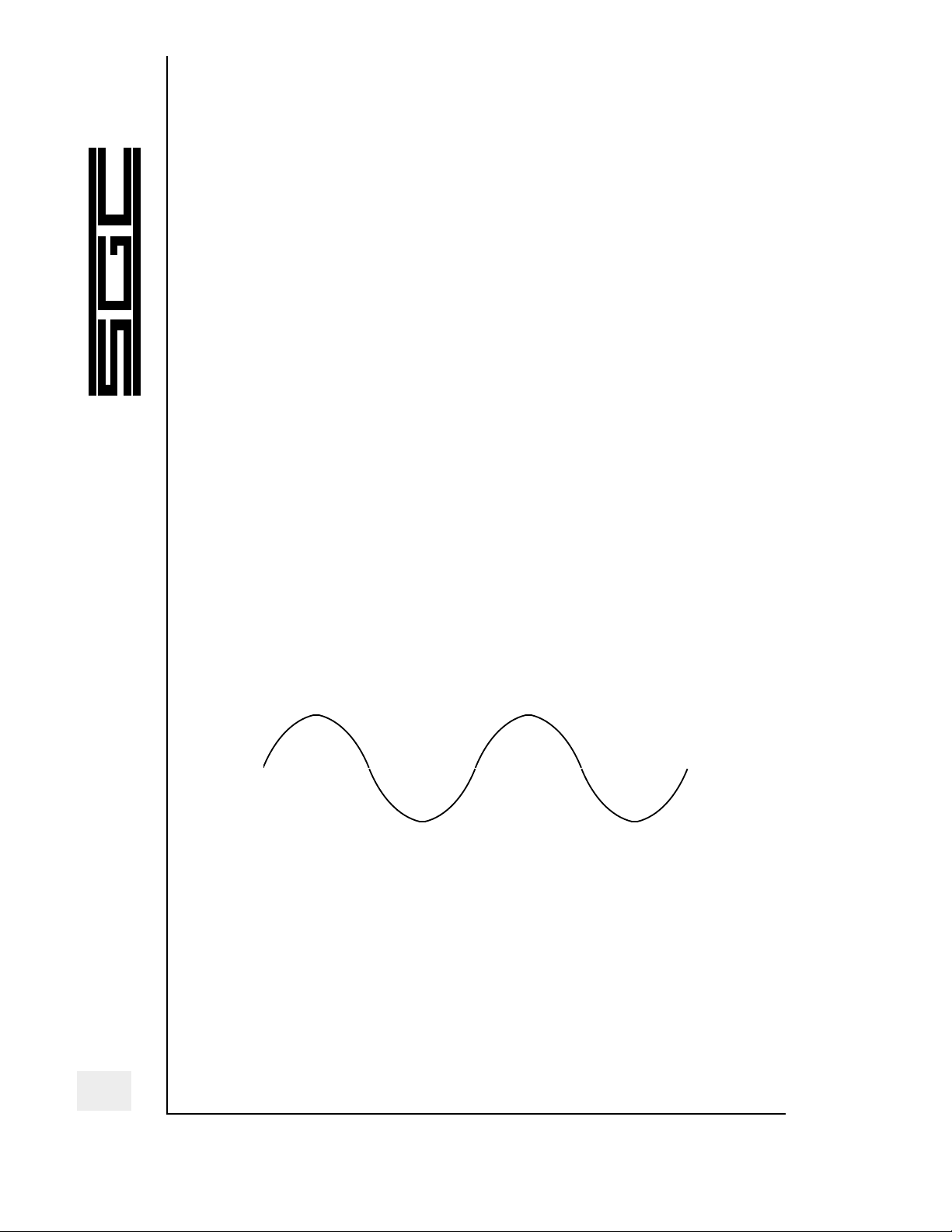
Those sound vibrations (called audio) travel in ripples, like
ripples in a pond when you toss in a rock. Ripples of water
will radiate out from the place that the rock splashed. The
height (amplitude) of the ripples will decrease as they move
farther away from the source of the splash. The amplitude of
the ripples represents the loudness of the sound.
Figure 1 — Simple ripple form
Frequency. The measure of each ripple from peak to peak
represents its frequency. The longer the measure, the lower
the frequency (and the deeper the sound pitch). The shorter
the measure, the higher the frequency (and the higher the
sound pitch).
2
SGC Inc. SGC Building,13737 S.E. 26th St. Bellevue, WA. 98005 USA
P.O.Box 3526, 98009 Fax: 425-746-6384 or 746-7173 Tel: 425- 746-6310 or 1-800-259 7331
E-mail: SGCMKTG@aol.com Website: http://www.sgcworld.com
© 1997 SGC Inc
Page 10
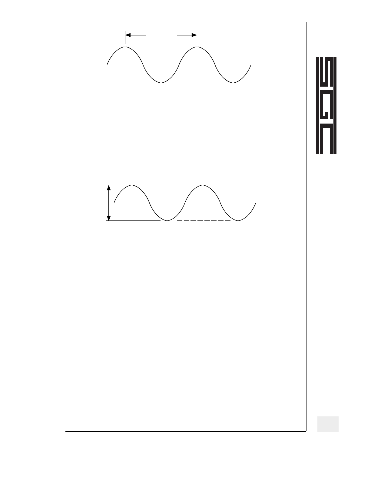
Figure 2 — Frequency of ripple from peak to peak
Amplitude. The measure of each ripple from peak to
trough represents its loudness (amplitude). In between the
peak and depth of the ripples, the level of the water is the
same as it is throughout the rest of the pond.
Figure 3 — Amplitude of ripple
from peak to trough
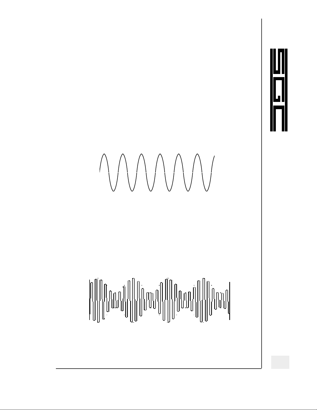
Complex audio signals, however, look much different from
those ripples on the pond. Whereas the pond ripples would
resemble single-tone audio signals (like ones from a tone
generator or tuning fork), complex sounds such as speech
and the sound of musical instruments comprise many different waves that overlap and mix together, a much more
jagged, complicated wave than any of those ripples on the
pond.
Storing and Retrieving Sound
When a microphone picks up a sound, it changes the sound
vibrations into electrical impulses. Inside the microphone,
the sound waves strike a thin element (typically a
diaphragm or ribbon). The movement of that element
3
SGC Inc. SGC Building,13737 S.E. 26th St. Bellevue, WA. 98005 USA
P.O.Box 3526, 98009 Fax: 425-746-6384 or 746-7173 Tel: 425- 746-6310 or 1-800-259-7331
E-mail: SGCMKTG@aol.com Website: http://www.sgcworld.com
© 1997 SGC Inc
Frequency
Amplitude
Page 11

through a magnetic field induces an electromagnetic signal
that will travel to an amplifier to boost the amplitude of the
tiny audio signals to a more usable level.
Storing sound. A phonograph record illustrates how the vibrational pattern from the microphone/amplifier translates
those electromagnetic signals into physical vibrations. The
vibrations, cut into the grooves of a vinyl disc, match the vibrations that the diaphragm made: waves that vary in
amplitude and frequency.
Figure 4 — Sound vibrations cut into the
sides of a long-play recording groove
Retrieving sound. To reproduce the sounds cut into the
vinyl record requires a phono cartridge very much like a
microphone: it contains an element that moves within an
electromagnetic field as the needle moves along in the
grooves. The width (amplitude) of the groove controls the
volume, and the rapidity (frequency) controls the pitch of
the sound.
The electrical impulses from the phono cartridge travel to an
amplifier, from which the strengthened signals travel to a
speaker to be reproduced again as vibrations in the air. The
electrical impulses cause the speaker voice coil to pump in
and out, causing the speaker cone to vibrate just as the
microphone element did, transmitting those vibrations
through the air—to your waiting ear.
Transmitting and Receiving Sound by Radio
This book concerns DSP in radio technology, transmitting and
receiving audio signals via the radio. This technology must
address how to transmit a radio frequency signal that also
4
SGC Inc. SGC Building,13737 S.E. 26th St. Bellevue, WA. 98005 USA
P.O.Box 3526, 98009 Fax: 425-746-6384 or 746-7173 Tel: 425- 746-6310 or 1-800-259 7331
E-mail: SGCMKTG@aol.com Website: http://www.sgcworld.com
© 1997 SGC Inc
Page 12
conveys an audio message. Consider that the typical voice
signal ranges from about 100 to 5000 Hz (.1 to 5 kHz) while
a typical radio signal might be transmitted on 7,200,000 Hz
(7200 kHz—in the 40-meter amateur band). Somehow, the
two signals have to be mixed together.
Modulation. One of the most common means to impress an
audio signal on a radio signal is amplitude modulation (AM).
The first component of the AM signal is the carrier. Just an
“empty” radio signal that contains no audio, the carrier is
called that because its only purpose is to carry an audio signal to receivers. A good way to hear a carrier is to tune in to
the AM broadcast band and tune in to a radio station. When
there is no audio and no static, you are hearing the carrier.
Figure 5 — A carrier signal without modulation
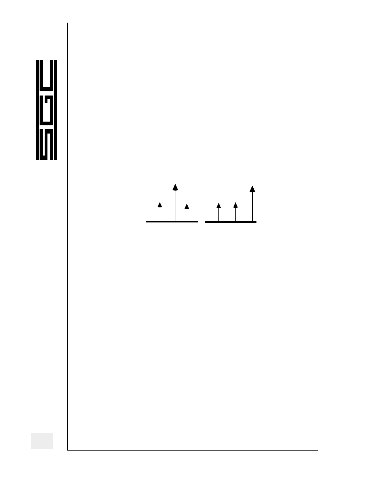
The amplitude-modulated signal has three basic components: the carrier, its upper sideband, and its lower sideband. When audio signals are added to an AM signal, the
carrier frequency remains at the exact frequency of the
radio signal.
Figure 6 — A carrier signal with modulation
The two audio signals, known as the upper sideband and the
lower side-band, appear on either side of the carrier. The
5
SGC Inc. SGC Building,13737 S.E. 26th St. Bellevue, WA. 98005 USA
P.O.Box 3526, 98009 Fax: 425-746-6384 or 746-7173 Tel: 425- 746-6310 or 1-800-259-7331
E-mail: SGCMKTG@aol.com Website: http://www.sgcworld.com
© 1997 SGC Inc
Page 13
upper sideband audio signal appears above the center of the
carrier, and the lower sideband audio signal appears below
the center of the carrier. As a result, if you tune your radio
to the center of an AM radio station, the audio often won’t be
as strong as if you tune slightly to either side of the center.
Sidebands. If you look at one of the sidebands on an oscilloscope (a video presentation of signal shapes), it will look
quite a bit like an actual voice signal. In single-sideband
(SSB) radio transmission, the carrier and one of the sidebands are filtered out of the AM signal and eliminated. All
that is transmitted is one of the audio sidebands.
Figure 7 — All the energy is concentrated
in the upper sideband (righthand diagram)
SSB transmission is important for two-way communications
in the HF band. All of the power that once was used to
amplify the carrier and two sidebands in an AM transmitter
can now concentrate in the remaining single sideband. And
now the SSB transmission requires only half the channel
width. As a result, an SSB signal sounds almost 10 times
louder than an equivalent AM signal. Because of its efficiency, ease of use, and good voice intelligibility, SSB is by far the
most-used radio transmission on the HF bands.
The modulated signal moves from the transmitter out
through the antenna and into the air. It travels through the
atmosphere for dozens or even thousands of miles. When it
is received by an antenna, the tiny radio signal passes into
the receiver. In the receiver, the signal is amplified, filtered,
and the audio deciphered. The deciphered audio signal goes
through the same processes described in Storing and
Retrieving Sound.
6
SGC Inc. SGC Building,13737 S.E. 26th St. Bellevue, WA. 98005 USA
P.O.Box 3526, 98009 Fax: 425-746-6384 or 746-7173 Tel: 425- 746-6310 or 1-800-259 7331
E-mail: SGCMKTG@aol.com Website: http://www.sgcworld.com
© 1997 SGC Inc
Page 14
Processing Sound Digitally
The sound processing we have discussed so far is called analog, a system in which audio and radio waves mimic the
sound waves they represent.
Digital signal processing changes analog audio signals into
digital impulses, that is into millions of numbers which
describe audio signals. The most common example of digital
technology is the compact disc (CD). Every wave of sound is
converted into binary code (1s and 0s). These numbers are
transmitted in such a way that the audio wave is “built” from
blocks of these numbers.
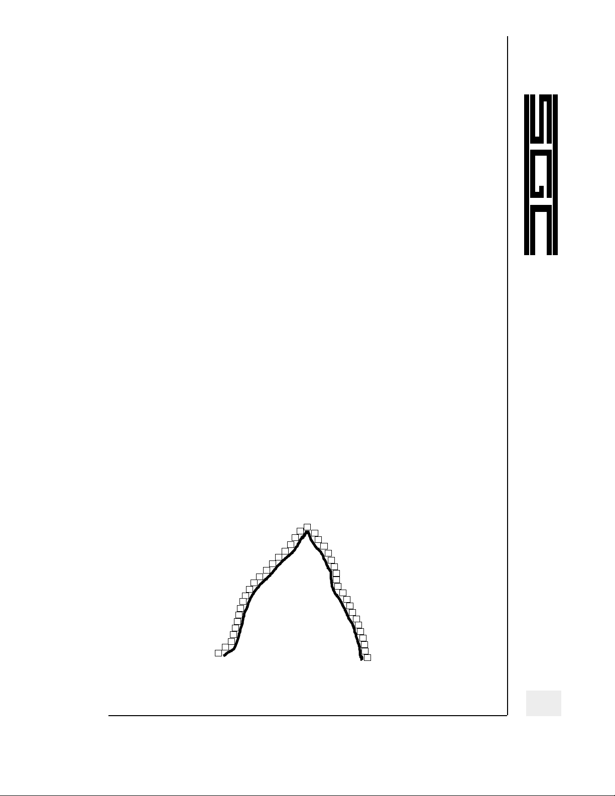
One way to think of these wave representations is to draw a
mountain on a sheet of paper. That’s the analog signal. For
the digital representation of this paper mountain, place the
wooden squares from a Scrabble game in rows over top of
the paper. With the wooden squares, you can represent the
mountain that you drew on the paper, except that the edges
of the block representation are blocky, not smooth. In actual
digital audio, the numeric building blocks are so tiny that
any blocky edges in the digital audio wave are undetectable.
Recording on Compact Discs
Although CD audio isn’t directly related to DSPs in high frequency radio use, CDs do offer a familiar example of digital
Figure 8 — Drawing of a mountain outlined in game
tiles makes a blocky pattern
7
SGC Inc. SGC Building,13737 S.E. 26th St. Bellevue, WA. 98005 USA
P.O.Box 3526, 98009 Fax: 425-746-6384 or 746-7173 Tel: 425- 746-6310 or 1-800-259-7331
E-mail: SGCMKTG@aol.com Website: http://www.sgcworld.com
© 1997 SGC Inc
Page 15

audio in the home. The music that is to be recorded onto a
compact disc—simply a thin disc of aluminum that is encased
in a plastic laminate to protect the recording—must be in a
digital medium; that is, it must be converted into massive
numbers of 1s and 0s. When the disc is recorded, much
error-correcting data and system information (like track
information and markers) also go onto the disc along with
the music. All of this data must be retrievable, so the aluminum disc is etched with minuscule pits. The pitted and
unpitted areas translate as the 1s and 0s that represent the
data.
In place of needle and cartridge of the analog record player,
a laser optical assembly retrieves the audio in a compact disc
player. This low-powered laser fires at the tracks of the disc.
The unpitted areas of the disc reflect its light back, but the
pitted areas reflect almost nothing. This tremendously fast
flickering of light is received by a photodetector that
changes the light flickers into binary electrical impulses.
These are then converted into analog impulses, which can be
amplified and converted into sound by the speakers.
Sampling. Of course the analog-to-digital and digital-toanalog processes are extremely complicated—especially when
you consider that such things as coding and sampling must
also occur in the system. Sampling is the process by which
the compact disc player retrieves an analog sound, then
checks the digital source for its accuracy, then plays another
sound. This cycling occurs 44,100 times per second (44.1
kHz), although many players now sample several times more
than that per second to make sure that the information being
received is accurate and not error-ridden. Such sampling at
harmonic frequencies is known as over-sampling. Many of
the high-cost compact disc players sample up to eight times
the standard sample frequency.
Volume.Relative sound volume also needs to be considered.
Every audio wave-form has a peak-to-peak length (the fre-
8
SGC Inc. SGC Building,13737 S.E. 26th St. Bellevue, WA. 98005 USA
P.O.Box 3526, 98009 Fax: 425-746-6384 or 746-7173 Tel: 425- 746-6310 or 1-800-259 7331
E-mail: SGCMKTG@aol.com Website: http://www.sgcworld.com
© 1997 SGC Inc
Page 16

quency of the sound), which determines the pitch of the
sound, and a height (the amplitude of the sound), which
determines its volume. In order for the compact disc player
to accurately reproduce music and not end up reproducing all
of the frequencies at the same volume, the sound samples
are quantified to a 16-bit number between 0 and 65,535.
Every tiny piece of audio can be reproduced by the compact
disc at any one of 65,536 different volume levels.
Compression. These codes that determine various aspects of
the compact disc’s sound and technical operations all require
a vast amount of information. A full compact disc of approximately 74 minutes requires in the neighborhood of 34 million bits of information to produce. If this information was all
held on a standard computer floppy disc, the selection would
have to be placed on 48 5.25” discs or 25 3.5” discs. Using a
compression code makes it possible for digital tapes and
MiniDiscs to be digital and hold as much music as they do.
Conclusion
You have seen how a complex radio carrier wave and its
audio signal can be filtered so only a sideband remains in
use. And you have seen how audio signals can be converted
to digital signals, in such forms as CDs.
In the next chapter, we look at the idea of filters that can
make changes in waves—whether those waves are sound
waves or radio frequency waves. And in Chapter 3, we look
at how digital signals can be processed for radio transmitting
and receiving.
9
SGC Inc. SGC Building,13737 S.E. 26th St. Bellevue, WA. 98005 USA
P.O.Box 3526, 98009 Fax: 425-746-6384 or 746-7173 Tel: 425- 746-6310 or 1-800-259-7331
E-mail: SGCMKTG@aol.com Website: http://www.sgcworld.com
© 1997 SGC Inc
Page 17

The Idea of Analog Filtering
Analog filters are used for a wide variety of applications in
electronics. One familiar application illustrates how filters
work: speaker crossover networks.
Analog Filters in Audio
Speaker crossovers usually consist of three different types of
filters that combine to channel audio to the proper speakers.
The typical speaker arrangement comprises a woofer (lowfrequency speaker), a midrange speaker, and a tweeter
(high-frequency speaker) for each channel of a sound system.
Filters make sure the appropriate audio frequencies at appropriate volume reach each speaker.
Crossover Network. The crossover consists of low-pass,
high-pass, and bandpass filters at the speaker inputs. Each
filter crops out certain frequencies and passes other frequencies.
Woofers. Most woofers are most effective in the several hun-
dred Hz range, so the low-pass filter might be set at 500 Hz.
All frequencies below 500 Hz (but little above that frequency) will pass to the woofer.
Tweeters. Similarly, most tweeters are effective above about
4 kHz, so the high-pass filter might be set at this frequency.
All frequencies above 4 kHz (but little below that frequency)
will pass to the tweeter.
Midrange. Midrange speakers use a more complicated filter—
a bandpass filter, which combines high-pass and low-pass filters to set both a high-frequency and a low-frequency limit
on the audio that passes through. This bandpass filter would
pass all frequencies that were in an audio band above 400 Hz
and below 4 kHz.
As a result of such filtering, these speakers produce good-
10
SGC Inc. SGC Building,13737 S.E. 26th St. Bellevue, WA. 98005 USA
P.O.Box 3526, 98009 Fax: 425-746-6384 or 746-7173 Tel: 425- 746-6310 or 1-800-259 7331
E-mail: SGCMKTG@aol.com Website: http://www.sgcworld.com
© 1997 SGC Inc
Chapter 2
Page 18

sounding audio and do not suffer damage from too much
power being applied to the wrong speaker.
Cutoff. Some audio enthusiasts say that if the audio is
cropped too sharply by the filters, it will sound sterile. So
design of speaker crossover filters provides for a more gradual filtering. The low-pass filter, for example, does not cut
off all audio at exactly 400 Hz. Rather it will gradually cutoff
the audio over the course of several hundred Hz or more,
passing everything below 400 Hz but gradually attenuating
audio above 400 Hz.
Figure 9 — This low-pass filter gradually
attenuates frequencies above 400 Hz.
Above 400 Hz is its “skirt.”
This slope of audio that is being attenuated by the filter is
known as the skirt, which describes that slope in a graph of
the filtered frequency.
Analog Filters in HF Radio
Standard HF radio filters are tunable bandpass filters.
Bandpass filters trim off the upper and lower frequencies
and pass signals within a certain range. The effect of a bandpass filter in radio is like the combination of a low-pass filter and a high-pass filter that passes audio to a midrange
speaker. Unlike crossovers, the radio filters should have as
close to straight skirts as possible. If they have wide skirts,
audio from adjacent stations and noise from outside of the
11
SGC Inc. SGC Building,13737 S.E. 26th St. Bellevue, WA. 98005 USA
P.O.Box 3526, 98009 Fax: 425-746-6384 or 746-7173 Tel: 425- 746-6310 or 1-800-259-7331
E-mail: SGCMKTG@aol.com Website: http://www.sgcworld.com
© 1997 SGC Inc
Page 19

radio signal will intrude on the tuned signal.
Therefore, radio bandpass filters are much more than a combination of low-pass and high-pass filters. With high-pass
filters, one side of the skirt can easily be tuned; with lowpass filters, the other side of the output can be adjusted.
Because the boundaries of these filters are not separately
tunable, adjusting the values of the components in the bandpass filter will affect both sides of the filter’s response.
Aside from the skirts of a filter’s output wave form, the
other components of this wave form are the area between
the skirts—the pass band—and the area where no signal passes through the bandpass filter—the stopband.
Symmetry.Another principal characteristic of bandpass filters is that of symmetry. Drawing a hypothetical line down
through the center of the bandpass waveform helps to see
the symmetrical shape of the output (just like the skirts help
to describe the filter characteristics).
To achieve a more symmetrical filter, most bandpass filters
combine several bandpass filters. The wave forms of these
filters mix together to form a composite passband wave
form. As a result, these complex filters have virtually sym-
metrical outputs.
The ideal passband from a bandpass filter is a square wave
in which nothing can be heard on either side of the passband, and the response across the top of the passband is
straight and unattenuated.
Crystal filters. In order to improve the characteristics of
passband filters, mechanical elements are often used instead
of the traditional combination of capacitors and coils (inductors). Because of lower cost and better performance compared with capacitance-inductance bandpass filters, quartz
crystal filters are often used in HF transceivers and communications receivers. The crystal filters are capable of steeper
skirts than the standard inductor/capacitor filters, and they
12
SGC Inc. SGC Building,13737 S.E. 26th St. Bellevue, WA. 98005 USA
P.O.Box 3526, 98009 Fax: 425-746-6384 or 746-7173 Tel: 425- 746-6310 or 1-800-259 7331
E-mail: SGCMKTG@aol.com Website: http://www.sgcworld.com
© 1997 SGC Inc
Page 20

also have more consistent quality.
Although analog filters are generally not variable at all,
some of the older receivers had a “Crystal Phasing” control.
This control was merely a tuning capacitor in the crystal filter which enabled the user to alter the shape of the band-
pass wave form to reduce nearby interference.
Mechanical filters. A more dramatic improvement, which
is covered further in the next section, is the mechanical filter. Mechanical filters, similar in design to crystal filters, use
metal elements instead of quartz crystal elements.
Mechanical filters are capable of much better characteristics
than the crystal filters—steep skirts, nearly flat passband,
and sharp stopband. But these filters are expensive to design
and construct.
HF filters in practical applications
Communications receivers and modern-day transceivers
must have several different filters. The filters allow the
receiver to pass a certain band through the radio and to the
speaker.
Wide bandpass.For a strong, high-fidelity AM signal, such
as from some shortwave broadcast stations, a very wide (8
to 15 kHz) filter will allow you to enjoy the audio to its
fullest. However, a wide filter such as this will permit adjacent-channel interference to pass through and will allow static to distort the signal.
Medium bandpass. So, for average AM broadcast listening,
a medium-width filter (between 4 and 6 kHz) is best
because it will keep out the static and interference, but will
allow enough audio to pass through to be somewhat pleas-
ant.
Narrow bandpass. For the narrow-width SSB voice signals,
a filter only 2- or 3-kHz wide is usually used. The audio
quality is fair for SSB, but is rather poor for listening to an
13
SGC Inc. SGC Building,13737 S.E. 26th St. Bellevue, WA. 98005 USA
P.O.Box 3526, 98009 Fax: 425-746-6384 or 746-7173 Tel: 425- 746-6310 or 1-800-259-7331
E-mail: SGCMKTG@aol.com Website: http://www.sgcworld.com
© 1997 SGC Inc
Page 21

AM broadcast (the AM broadcast will sound “muddy” and
will be difficult to decipher). For extremely narrow digital
modes (such as Morse code), the filters used are typically
between 0.1 and 1 kHz wide. At these widths, it is difficult to
understand any voice communications; very little audio can
pass through, except for the dots and dashes of Morse code.
Conclusion
You have seen how analog filters can make changes in
waves—whether those waves are sound waves or radio frequency waves—to improve high fidelity audio performance
and to improve radio reception by excluding unwanted frequencies and static. In the next chapter, we look at how digital signals can be processed for radio transmitting and
receiving.
14
SGC Inc. SGC Building,13737 S.E. 26th St. Bellevue, WA. 98005 USA
P.O.Box 3526, 98009 Fax: 425-746-6384 or 746-7173 Tel: 425- 746-6310 or 1-800-259 7331
E-mail: SGCMKTG@aol.com Website: http://www.sgcworld.com
© 1997 SGC Inc
Page 22

DSPs in HF Communications
Digital transmissions are nothing new. Morse code, which is a
binary alphabet (dots and dashes instead of 1s and 0s), is
approximately 100 years old. Another technological development that people assume is recent, facsimile transmission
(FAX), had been successful in radio transmission nearly 70
years ago. But the high cost of technology made fax
machines infeasible until the advent of the personal and
business telephone-based fax machines in the 1980s.
Figure 10 — Morse Code sending key
Like binary codes and facsimile, DSP has existed in theory
since the early 20th century. DSP manipulates a digital signal. A box that digitally alters the acoustics of a symphony
recorded on CD is a type of DSP. Equipment that digitally
eliminates the time-delayed echo in telephone lines is
another type of DSP.
Whatever their application, all DSPs use many of the same
DSP microprocessor “chips.” The differences between the
applications aren’t the DSPs alone; rather they are in what
we program them to do. So the general category of DSP is extremely broad.
DSP Flow Chart
The flow chart of every basic application in which DSP is
used is the same. An analog signal (either audio or video)
enters the digital section of the equipment.
15
SGC Inc. SGC Building,13737 S.E. 26th St. Bellevue, WA. 98005 USA
P.O.Box 3526, 98009 Fax: 425-746-6384 or 746-7173 Tel: 425- 746-6310 or 1-800-259-7331
E-mail: SGCMKTG@aol.com Website: http://www.sgcworld.com
© 1997 SGC Inc
Chapter 3
Page 23

Sample and Hold. The first stage of the system is the sam-
ple and hold. The S/H circuit samples the signal and holds
each sample briefly, for example the amplitude of the incoming signal at a specific time.
In the typical CD player, the sampling frequency is 44.1 kHz,
which means that the amplitude of the incoming audio signal
is sampled 44,100 times per second! The sampling rate for CD
players is high because high-quality audio is more complex
than telephone or HF communications, where the fidelity is
often deliberately reduced to make the signals both easier to
understand and more efficient. In these systems, the sampling rate will often be as low as 8 kHz.
Figure 11 — A home CD player
The basic guideline for determining the sampling rate is that
it must be at least twice the greatest frequency that you
expect to reproduce. So, if the maximum frequency of the CD
player audio is 20 kHz, two times this frequency (40 kHz) will
still fall well within the “two times” guideline. For the 8-kHz
sampling rate of the telephone system, you can expect that
the highest frequency that can be reproduced is 4 kHz (near
the top of the spectrum for the average voice frequency).
Analog to Digital. At the next stage, the analog-to-digital
converter (ADC), the millions of tiny audio “slices” from the
sample-and-hold circuit are converted into binary numbers.
ADCs operate in a variety of ways; some count with a “staircase” generator while others convert the analog voltage into a
digital value with multiple comparators. The quality or usefulness of an ADC can be determined by its accuracy, complexity, and speed.
16
SGC Inc. SGC Building,13737 S.E. 26th St. Bellevue, WA. 98005 USA
P.O.Box 3526, 98009 Fax: 425-746-6384 or 746-7173 Tel: 425- 746-6310 or 1-800-259 7331
E-mail: SGCMKTG@aol.com Website: http://www.sgcworld.com
© 1997 SGC Inc
Page 24

Several other methods for converting the data also exist;
choice in methods depends on whether you want low cost,
high-speed processing, or the ability to process massive
amounts of data. The ADC selection is an important consideration at this point, but as technology advances and the prices
decrease, it will become less a factor.
DSP. The actual DSP stage is next in the lineup. This chip—
really a central processing unit commonly called a “computer
chip”— might be programmed as a filter to reduce noise in a
system, it might be programmed to produce or eliminate
audio echo, it might be used to clarify a video signal, or it
might be programmed to do any one of numerous other
tasks.
Digital to Analog. The next stage of the DSP system is
another that is used in standard digital audio applications,
the digital-to-analog converter (DAC). The DAC does the
same things as the ADC, only backwards. Its measures of
quality (accuracy, complexity, and speed) are also the same
as for the ADC. Like the ADC, it can also use a number of different methods to accomplish digital-to-analog conversion.
In one type, the DAC counts digital pulses to determine the
analog output. Others use such techniques as voltage or current conversion and oversampling to achieve the output.
Like ADC converters, the problems in using DAC chips should
decrease as the circuits become more complex and less
expensive.
Low-pass filter. The output of the DAC is blocky waveform
that would look like the Scrabble block mountain from earlier in this book, so that it is sometimes called a staircase
waveform. Here the last section of the DSP (a low-pass filter)
is used: it smooths out the rough stairs in the waveforms.
This process sounds simple enough, but sometimes five or
more different analog and digital stages are used in some
smoothing filters.
17
SGC Inc. SGC Building,13737 S.E. 26th St. Bellevue, WA. 98005 USA
P.O.Box 3526, 98009 Fax: 425-746-6384 or 746-7173 Tel: 425- 746-6310 or 1-800-259-7331
E-mail: SGCMKTG@aol.com Website: http://www.sgcworld.com
© 1997 SGC Inc
Page 25

DSP Evolution
Experimental use of DSPs in one form or another was occurring in the 1950s and 1960s. However, because of the enormous cost of early computers, this research was limited to
large university and government research facilities. In the
1970s and 1980s, DSPs began to break away from the university and government centers, moving toward high-powered personal computers with central processing units, such
as the Intel 8086 and 8088 semi-conductor chips.
Figure 12 — A semi-conductor “chip”
Because the manufacturers of semiconductors realized the
potential for DSP, they began to create specialized DSP chips
that could perform signal processing faster and more efficiently than standard microprocessor chips. Today, companies such as Motorola, Texas Instruments, and Analog
Devices have several hundred variations on their DSP chips,
for differing applications and budgets.
As the technology of computer and DSP chips has increased
in sophistication and the prices have dropped, several innovative companies have developed DSPs for use in different
aspects of HF communications.
DSPs in Transmitting Applications
A number of advances in transmitter design and efficiency
in HF communications have made use of DSP technology, but
they do not have the same dramatic effect in cost or performance that DSPs make in receiver filter applications.
DSPs in Speech Processing.
The speech processor in one
transceiver is heavily intermeshed with its method of SSB
modulation. This transceiver uses a system of low-pass and
18
SGC Inc. SGC Building,13737 S.E. 26th St. Bellevue, WA. 98005 USA
P.O.Box 3526, 98009 Fax: 425-746-6384 or 746-7173 Tel: 425- 746-6310 or 1-800-259 7331
E-mail: SGCMKTG@aol.com Website: http://www.sgcworld.com
© 1997 SGC Inc
Page 26

high-pass filters to reduce the bandwidth of the voice signal
and make the transmitter more efficient. The high-pass filter is adjustable so that the operator can choose from several different selections. This filtering will slightly alter the
sound of the voice (make the voice sound stronger or tinnier) and possibly help it cut through the static a bit better.
DSP in SSB Generation. One transceiver uses direct modulation to impose audio on the transmitted signal. Rather than
using an analog filter to remove the unwanted sideband
when creating a single-sideband signal, the transceiver uses
a DSP. Because digital audio is mathematically based, its timing is almost perfect—perfect timing and audio control being
essential for phase-based work.
DSP in Phase Delay
Aside from use in applications requiring delay, a phasedelay system can also entirely filter out a signal. This system
eliminates a signal by adding another.
Out-of-Phase Signal. Because every audio signal has a
positive cycle and a negative cycle, phase-shift sideband
elimination works by inserting a duplicate of the original
signal at exactly the opposite phase, a signal at exactly the
same amplitude of the original. While the signal is in the
positive cycle and its exact duplicate is in the negative cycle,
the two waves cancel each other out and no signal remains.
Because of its exactness, this system is much more precise
than analog phase shifters, which sometimes allow trace
amounts of the other sideband to remain in the signal.
Phase Shifting Networks. After the remaining modulated
signal is limited in bandwidth by a low-pass filter, it runs
through several phase-shifting networks to produce an SSB
signal free from noise outside the band of voice frequencies.
A digital filter suppresses the carrier so that only the SSB
modulation wave passes out.
19
SGC Inc. SGC Building,13737 S.E. 26th St. Bellevue, WA. 98005 USA
P.O.Box 3526, 98009 Fax: 425-746-6384 or 746-7173 Tel: 425- 746-6310 or 1-800-259-7331
E-mail: SGCMKTG@aol.com Website: http://www.sgcworld.com
© 1997 SGC Inc
Page 27

DSP in CW modulation
CW (Morse code) modulation is simple: turn the transmitter
on; turn it off; turn it on; turn it off. Typically, the action of
the transmitter being keyed on and off skews the waveform.
Figure 13 — “Perfect” CW modulation
A perfectly modulated Morse code signal would be a set of
square waves. The beginning of the wave would rise instantly, stay steady for a length of time (determined by either a
dot or a dash), then drop sharply down. Some Morse code
transmitters “click” while in the CW mode, as a result of an
improper waveform. This DSP system can eliminate any
clicks and any other peculiar sounds that improperly modulated CW signals can make. The result is perfectly shaped
Morse code. Of course modern transceivers in good working
order rarely suffer noticeable modulation (or key on/off)
problems.
DSPs in Receiving Applications
Because transmitting a powerful signal is only half of the
game in HF communications, the real differences are these
factors: patience, “good ears,” a great receiver, and an excellent antenna. DSP can’t help much with “good ears,” but it
can dramatically improve the quality of a receiver for the
operator who has been straining through the static and heterodynes for several hours.
Standard DSP filters. DSP filters in HF communications
equipment are standard bandpass filters that pass a certain
segment of the radio band through the radio into speakers or
Dot Dash
20
SGC Inc. SGC Building,13737 S.E. 26th St. Bellevue, WA. 98005 USA
P.O.Box 3526, 98009 Fax: 425-746-6384 or 746-7173 Tel: 425- 746-6310 or 1-800-259 7331
E-mail: SGCMKTG@aol.com Website: http://www.sgcworld.com
© 1997 SGC Inc
Page 28

headphones. These filters offer lower cost and improved
flexibility over mechanical filters.
Analog. In analog filters, a number of standard parts, con-
figurations, and equations determine the values of components. Analog filters take more of a hands-on approach to
electronics; the electronics designer and user can actually
see the effects of the work. The components have a direct
impact on the electrical signals that pass through them.
Digital. Although digital filters are modeled after analog fil-
ters, and although their characteristics are based on analog
filters, the design and applications of digital filters are
entirely different. Digital filters employ a specialty DSP chip
for each of the filtering functions. Instead of using separate
components to control the filter functions, the bandpass filtering and other accessory functions are all controlled by
programming instructions and equations in the chip. Rather
than substituting parts for better performance (as in analog
filter design), the digital filter designer programs better
equations and instructions into the chip.
As a result, equations control and alter the binary numbers
that pass through the DSP chip. The end result is that the
numbers are converted back into tangible audio signals,
which have been altered during the earlier binary numbers
stage. In this respect, digital filter design is much more theoretical in approach than is analog design.
Programming. Because of the difference between analog
and digital filter construction, the digital filters depend more
on good programming than on good quality components. Of
course, the circuits must be solid, but there are few differences between the important components in various digital
filters—a filter could easily be changed from excellent to
ineffective by merely changing its programming.
Because digital filters are both created and limited by their
instructions, they can also be changed to anything, according
21
SGC Inc. SGC Building,13737 S.E. 26th St. Bellevue, WA. 98005 USA
P.O.Box 3526, 98009 Fax: 425-746-6384 or 746-7173 Tel: 425- 746-6310 or 1-800-259-7331
E-mail: SGCMKTG@aol.com Website: http://www.sgcworld.com
© 1997 SGC Inc
Page 29

to their instructions. As a result, adjusting a variable resistor
can continuously change the width of a bandpass filter. Also,
changing some of the parameters within that filter changes
some of its characteristics. This flexibility means that for less
than the price of one good mechanical filter, a DSP company
can develop the equivalent of dozens (or possibly hundreds)
of different filters.
Continuously Variable DSP Filters. Until recently, filters
have been single bandwidth (except for slight alterations in
response from crystal phasing control). With the advent of
real-time digital filters, the bandpass frequencies can now be
changed in width, depending on the operator’s particular
receiving needs.
JPS Communications has developed a process for HF filters
that is known as dynamic peaking. Like any DSP system, the
received signal is constantly being sampled by the sampleand-hold portion of the analog-to-digital converter. But,
in JPS’s design, the DSP also works as a filter while it is mon-
itoring the width of the signal that is being received. If the
signal is narrow, the sample-and-hold checks it and automatically narrows the filter width. If the signal becomes
wider, the sample and hold checks it and automatically
widens the filter response so that the signal can easily be
heard.
This sort of “smart filter” obviously depends on fast sampling
times and accurate filter software. If the DSP was based on a
slow-sampling DSP or on one of the older chips that didn’t
work in the real time, then the DSP would sample the signal
and noticeably change the bandwidth at a point after the
bandwidth of the signal had narrowed or widened.
As a result, if the DSP hardware reacted slowly, the received
signal would be occasionally cut off at the beginning of
words (because the bandwidth would still be narrow from
the preceding pause) or it would be laced with bursts of
22
SGC Inc. SGC Building,13737 S.E. 26th St. Bellevue, WA. 98005 USA
P.O.Box 3526, 98009 Fax: 425-746-6384 or 746-7173 Tel: 425- 746-6310 or 1-800-259 7331
E-mail: SGCMKTG@aol.com Website: http://www.sgcworld.com
© 1997 SGC Inc
Page 30

interference (because the bandwidth would still be wide
from the preceding speech). Similar problems would occur if
the software for the devices was even slightly inaccurate.
RF Attenuator. Some portable and modern solid-state
receivers feature RF attenuators. (RF is radio frequency, the
signals that your transceiver receives; attenuation is the
weakening of signals.) Solid-state radios are prone to over-
loading from strong signals.
A strong signal will saturate the circuits which separate the
audio signal from the carrier, causing that signal to be heard
on several or possibly many frequencies. As a result, RF
attenuators are used to decrease the strength of the signals
into the radio. With the digitized audio of a DSP, this function
can easily be programmed into the chip.
(RF attenuators can be handy if your receiver is a block
away from another amateur operator who operates at the
edge of the legal limit. Otherwise, if the transceiver really
needs the RF attenuator for typical service, you might want
to look into purchasing a transceiver with a better front
end.)
DSP Filters: High-pass, Low-pass, Bandpass
High-pass, low-pass, and bandpass filters are often used in
HF transceiver antenna input circuits for two purposes: to
prevent strong out-of-band signals from saturating or overloading the receiver’s front end and being heard throughout
different bands; and to prevent adjacent-band signals from
splattering over into other regions.
High-pass Filters. The most common high-powered local
radio stations would be those in the AM broadcast band. The
HF band is higher in frequency than the AM broadcast band,
so these image signals could all be virtually eliminated with
a high-pass filter. For example, if you live near a 10-kW AM
broadcast station, you might have problems with hearing
23
SGC Inc. SGC Building,13737 S.E. 26th St. Bellevue, WA. 98005 USA
P.O.Box 3526, 98009 Fax: 425-746-6384 or 746-7173 Tel: 425- 746-6310 or 1-800-259-7331
E-mail: SGCMKTG@aol.com Website: http://www.sgcworld.com
© 1997 SGC Inc
Page 31

that station as an image throughout the HF spectrum. If you
are attempting to hear a weak signal, this overload can
destroy your ability to hear the wanted station. A high-pass
filter with a cut-off frequency around 1700 kHz can prevent
these AM broadcast stations from interfering with the shortwave frequencies.
Low-pass Filters. U.S. television channel 2 at 55 MHz is just
above the HF frequencies so these image signals could all be
virtually eliminated with a low-pass filter. (In some parts of
the world, television broadcasts at a frequency as low as 45
MHz.)
Figure 14 — Filters permit setting audio
quality to personal preference
Bandpass Filters. Low-pass and high-pass filters are used
less often than bandpass filters, however, to lock out unwanted signals. High power shortwave broadcast stations are on
the air throughout the world. In the United States, 50-kW AM
stations and 1 MW television stations broadcast at the edges
of the amateur bands. In amateur radio transceivers, the typical solution would be to make the bandpass filter run from
the bottom edge of the amateur band to its top edge. All tres-
24
SGC Inc. SGC Building,13737 S.E. 26th St. Bellevue, WA. 98005 USA
P.O.Box 3526, 98009 Fax: 425-746-6384 or 746-7173 Tel: 425- 746-6310 or 1-800-259 7331
E-mail: SGCMKTG@aol.com Website: http://www.sgcworld.com
© 1997 SGC Inc
F
V
Without filter
F
V
With high frequency filter
F
V
With low frequency filter
F
V
With low and High filter
HIGH FREQUENCY
FILTER
High frequency
corner can be adjusted
in 100Hz steps
Low frequency corner
can be adjusted in
100Hz steps
LOW FREQUENCY
FILTER
CENTER FREQUENCY
FILTER
Bandpasss center
frequency can be
adjusted in 100Hz
steps
Page 32

passing signals would be virtually eliminated. Consequently,
bandpass filters have become the mainstay of DSP use in HF
equipment.
Of course, all of these filters to eliminate strong image signals in the receiver can be programmed into DSP chips. And
because the cost for these extra filters is so low, they can be
included in modern receivers—even though they were too
expensive to be included in most earlier receivers.
Notch Filters
In HF communications, notch filters serve to eliminate nearby sources of interference. Notch filters are also known as
band-rejection filters and band-elimination filters, names
that provide an insight into their inner workings.
Figure 15 — The SGC Notch filter can suppress up to
five tones at once
Instead of passing a tiny segment (or even a large segment)
of the band through and rejecting all other signals, the notch
filter rejects a tiny segment of the band and allows all other
signals to pass through, unattenuated.
Band Interference. A notch filter can eliminate some
interference within the band. A radio signal might be overwhelmed by Morse Code interference, but a notch filter on
an analog receiver can tune out some of the interference. On
many analog receivers, the notch filter settings provide little
improvement. And even an excellent notch filter can reduce
the interference of only one signal. The notch filters in the
DSP designs often perform amazingly. Rather than just
blocking out a nearby band segment, they act as true
“killers” of whistle or heterodyne interference.
25
SGC Inc. SGC Building,13737 S.E. 26th St. Bellevue, WA. 98005 USA
P.O.Box 3526, 98009 Fax: 425-746-6384 or 746-7173 Tel: 425- 746-6310 or 1-800-259-7331
E-mail: SGCMKTG@aol.com Website: http://www.sgcworld.com
© 1997 SGC Inc
F
V
With Notch Filter
Interfering tones are
suppressed by 40dB
and up to five tones
can be notched out
simultaneousely
NOTCH FILTER
F
V
Without Notch Filter
Tone interferences
Page 33

Heterodyne Interference. A heterodyne is a shrill tone
that is caused when radio signals overlap. In the amateur
bands, where nearly anyone can transmit nearly anywhere,
heterodynes can cause a real problem, especially in the 80and 40-meter amateur bands, where shortwave stations
broadcasting in the AM mode can be readily heard. The mixture of AM and SSB signals results in an amateur band riddled with heterodynes. Heterodynes are not only unpleasant
to listen to, but they can ruin an operator’s ability to hear a
signal; as a result, heterodynes have been one of the plagues
of radio communications since its creation.
DSP notch filters are effective against heterodynes—most can
be entirely eliminated. More importantly, they can eliminate
several heterodynes at the same time. The DSP notch filter
chip is programmed to eliminate all constant or slowly varying tones present in receiver or transceiver audio. In this
sense, they behave differently than typical notch filters. If
the digital notch filter can eliminate one of the worst enemy
of the HF communications user, the heterodyne, we wonder
what other miracle it can achieve—eliminate fading?
Digital AGC
Automatic gain control (AGC), also known as an automatic
level control (ALC), is especially important when receiving
wideband modes, such as AM, that are susceptible to fading.
Because of fading, signals will quickly rise and fall in level.
AGCs level out only the amplitude of the signals that pass out
of the receiver; therefore, they can easily be programmed
into DSP chips. Because the technology for analog AGCs was
already solid, the only real benefit of digital design is to save
money in applications where a DSP chip is already being
used: using a DSP simply for a digital AGC would be expensive.
26
SGC Inc. SGC Building,13737 S.E. 26th St. Bellevue, WA. 98005 USA
P.O.Box 3526, 98009 Fax: 425-746-6384 or 746-7173 Tel: 425- 746-6310 or 1-800-259 7331
E-mail: SGCMKTG@aol.com Website: http://www.sgcworld.com
© 1997 SGC Inc
Page 34

Conclusion
You have seen how DSP has transformed the quality of HF
communications in both transmit and receive. Next, we will
look at available equipment which features DSP.
27
SGC Inc. SGC Building,13737 S.E. 26th St. Bellevue, WA. 98005 USA
P.O.Box 3526, 98009 Fax: 425-746-6384 or 746-7173 Tel: 425- 746-6310 or 1-800-259-7331
E-mail: SGCMKTG@aol.com Website: http://www.sgcworld.com
© 1997 SGC Inc
Page 35

Available DSP HF equipment
As DSP technology is beginning to reach the marketplace, DSP
products are finding their way into HF communications.
Figure 16 — SGC's DSP products: PowerTalk, SG-RM
remote mobile head, and PowerClear.
DSP Transceivers
A number of transceivers currently on the market offer digital signal processing. This book, coming from SGC, designer
and manufacturer of HF communications equipment, has
been setting the stage for this biggest technological advance
in two-way communications since the use of the SSB mode
and the development of the single-unit transceiver.
SGC’s SG-2000 PowerTalk. Presently, the equipment that
Figure 17 — The PowerTalk Transceiver
28
SGC Inc. SGC Building,13737 S.E. 26th St. Bellevue, WA. 98005 USA
P.O.Box 3526, 98009 Fax: 425-746-6384 or 746-7173 Tel: 425- 746-6310 or 1-800-259 7331
E-mail: SGCMKTG@aol.com Website: http://www.sgcworld.com
© 1997 SGC Inc
Chapter 4
Page 36

uses the state-of-the-art DSP filtering technology is the SG2000 PowerTalk.
The SG-2000 PowerTalk offers the most DSP features for the
lowest price. Some of the key DSP-related features of the SG-
2000 PowerTalk are these:
• ADSP™ noise-reduction system
• SNS™ noise-reduction system
• First mobile/base HF transceiver with DSP
• First HF DSP system with visual display
• DSP filters can be programmed into separate
memories
• Notch filter
• Eight preset DSP filter positions
• Variable high-pass, low-pass, and bandpass filters.
• Separate control head makes upgrade from SG-2000
to SG-2000 PowerTalk simple and inexpensive
ADSP™ noise reduction. ADSP (Adaptive Digital Signal
Processing) is a particularly effective type of noise-reduction
system to filter out unwanted noise in any signal being
received. The DSP algorithm is “smart” and can “see” the dif-
Figure 18 — SGC
’s ADSP substantially
reduces noise level
ference between the signal being received and the accompanying white noise and static crashes. Then, it separates the
two and passes only the received signal to the speaker.
SNS™ noise reduction. SNS (Spectral Noise Subtraction) is
29
SGC Inc. SGC Building,13737 S.E. 26th St. Bellevue, WA. 98005 USA
P.O.Box 3526, 98009 Fax: 425-746-6384 or 746-7173 Tel: 425- 746-6310 or 1-800-259-7331
E-mail: SGCMKTG@aol.com Website: http://www.sgcworld.com
© 1997 SGC Inc
Noise level is
subtantially
reduced
ADSPª
F
V
Without ADSP
F
V
With ADSP
Noise level
Page 37

revolutionary DSP noise reduction used only in the SG-2000
PowerTalk and in one of the DSP “black boxes.” Instead of
the traditional method of filtering whereby signals are
passed through a bandpass filter with a concrete shape, the
SNS system acts more like a continuously variable bandpass
filter.
Figure 19 — SGC’s SNS subtracts spectral noise
With SNS noise reduction, the filter basically collapses
against the radio signal (either voice or data). As a result, the
receiver (and any interference during that audio) remains,
but the noise between the bits of audio information is eliminated. (It’s a little like Dolby processing for high fidelity
recording.)
First mobile DSP transceiver. Compared with other DSP
transceivers, the SG-2000 PowerTalk is small (4.75” x 10” x
15”), light (12 lbs), and made specifically for 12-volt operation. On the road, on a boat, or on a DXpedition, where the
conditions are much less than ideal, you will especially notice
the benefits of the DSP functions.
Visual DSP filter display. None of the other HF DSP filters
show you the exact settings of the filters. In a few cases,
adjustable filters are controlled with rotary knobs with the
increments marked around them.
In the SG-2000 PowerTalk, the filter positions (from 300 to
3000 Hz) are adjustable (in 100-Hz steps) and each step is
displayed as an LED on the front panel. With this LED display
system, you can immediately see the width and the exact
frequency coverage of the filter that you are using at any
given time. This system is particularly useful if you need to
dial between many different frequencies and if the signals
are of varying strengths and characteristics.
30
SGC Inc. SGC Building,13737 S.E. 26th St. Bellevue, WA. 98005 USA
P.O.Box 3526, 98009 Fax: 425-746-6384 or 746-7173 Tel: 425- 746-6310 or 1-800-259 7331
E-mail: SGCMKTG@aol.com Website: http://www.sgcworld.com
© 1997 SGC Inc
F
V
With SNS
The noise of the
unused bands of
frequencies are
totally substracted
SNSª
F
V
Without SNS
V
Page 38

Programmable digital filters. Wishing to contact a station
on a regular basis, you might find that a certain filter setting
works well day after day for listening to that station. For
your convenience, you can preset this filter setting into the
radio memories (along with six other favorite filter settings).
With a push of a button, you can immediately place the SG2000 PowerTalk in your favorite filter position.
Pre-programmed filter settings.In addition to the enormous array of filter settings that you can create, eight standard settings are preprogrammed into the memories. Some of
the most common of these positions are marked with LEDs
for extra convenience.
Notch filter. The notch filter can locate and eliminate as
many as five heterodynes at one time—many more than you
will probably ever need to use!
Variable Bandpass, low-pass, and high-pass filters.
The SG-2000 PowerTalk has variable bandpass, low-pass,
and high-pass filters. These filters are one of the contributors
to good radio reception. These accurately displayed, excellent
variable filters could easily make the difference between a
copyable signal and an unreadable signal amidst the noise.
Upgradable DSP head. Instead of buying a new transceiver for the DSP functions, you can simply purchase the SG2000 PowerTalk head and place it on the SG-2000 transceiver case. Doing so could save you thousands of dollars over
upgrading to a new PowerTalk transceiver.
Other Advantages. In addition to the DSP advantages of
the SG-2000 PowerTalk, this model also has a number of
other advantages:
Removable Head. Unlike other HF transceivers, the entire
face plate (“head”) of the SG-2000 can be detached and used
to operate the transceiver from remote locations—or in tandem with other heads. This feature is perfect for commercial
and marine operation, or for club amateur stations where a
31
SGC Inc. SGC Building,13737 S.E. 26th St. Bellevue, WA. 98005 USA
P.O.Box 3526, 98009 Fax: 425-746-6384 or 746-7173 Tel: 425- 746-6310 or 1-800-259-7331
E-mail: SGCMKTG@aol.com Website: http://www.sgcworld.com
© 1997 SGC Inc
Page 39

transceiver must be controlled from more than one location.
Simple design of front-panel controls. Instead of cram-
ming dozens of tiny knobs and buttons on the front panel,
SG-2000 PowerTalk displays only three knobs and a few
rows of buttons. Not that the PowerTalk lacks features, but
rather that it is so well designed that fewer buttons accomplish the same functions.
Even the DSP section of the PowerTalk—which features custom DSP memories, preprogrammed filter memories, a notch
filter, a noise reducer, the SNS noise reducer, variable lowpass, high-pass, and bandpass filters, and a bypass function—
requires only nine buttons. On the simplified panel, the buttons are large and spaced widely apart—there’s little chance
that you will misprogram the PowerTalk head. This simplified design is significant when you compare the SG-2000
Power-Talk with the many-knobbed alternatives.
High-power/small package. In spite of having the most
flexible and highly developed DSP unit in any transceiver
and being one of the highest-powered transceivers available
(conservatively rated at 150 watts), the SG-2000 is small. As
mentioned earlier, the SG-2000 PowerTalk is a mere 4.74" x
10" x 15" at 12 pounds. You get everything in a package that
you can take anywhere.
Tested for high quality. No other transceivers advertise
their testing procedures as SGC does. After it has been manufactured in the United States using high-quality components,
every SG-2000 is factory-aligned. Then, each rig is keyed at
full power into an open antenna for 10 seconds, then into a
shorted antenna for another 10 seconds. Next, it is keyed for
24 straight hours in full-power CW. Each SG-2000 is then
keyed on and off at 10-second intervals for 24 hours.
Finally, each SG-2000 is re-evaluated and all functions are
verified to ensure that performance meets specifications.
After the SG-2000 passes these difficult tests, it may leave
the factory. As a result of this quality, the SG-2000 is one of
32
SGC Inc. SGC Building,13737 S.E. 26th St. Bellevue, WA. 98005 USA
P.O.Box 3526, 98009 Fax: 425-746-6384 or 746-7173 Tel: 425- 746-6310 or 1-800-259 7331
E-mail: SGCMKTG@aol.com Website: http://www.sgcworld.com
© 1997 SGC Inc
Page 40

the few amateur transceivers that is also type-accepted for
commercial and marine service.
The bottom line is that the SG-2000 PowerTalk is one of the
best-constructed, most flexible, most advanced, highestpowered, and easiest-to-use transceivers on the market.
And the list price is just over half the price of the only other
DSP transceivers.
Add-on DSP
Because DSP technology has become much more affordable, a
number of different manufacturers have developed external
DSP boxes to serve many of the same purposes as built-in
DSP. Instead of connecting inside the radio, they connect
between the headphone audio output jack and the headphones. All DSP conversions and alterations occur after the
audio signal has passed out of the receiver. This makes DSP
use and installation quite simple.
One of the major markets for the black boxes is radio amateurs. Combine these two features and you can assume that
the target candidate will be a contest-entering amateur who
is busily digging out weak, static-laden SSB and CW signals
from the far corners of the world. Because the filters are
intended for such difficult situations, they are typically narrow and effective for poor signal situations and not for solid,
high-fidelity signals. Fortunately, the manufacturers of these
boxes include easy pushbutton switches so that the filters
can be quickly punched in and out.
Basic Features. Even when the DSP programming varies
among the basic bandpass filters, the results are essentially
the same. Because these filters create a square-wave filter
response, most of the filter responses of the equipment on
the market are good, and differences among them are slight.
Although the boxes might vary in the number of features
that it supplies, each box includes at least one of these three
major features:
33
SGC Inc. SGC Building,13737 S.E. 26th St. Bellevue, WA. 98005 USA
P.O.Box 3526, 98009 Fax: 425-746-6384 or 746-7173 Tel: 425- 746-6310 or 1-800-259-7331
E-mail: SGCMKTG@aol.com Website: http://www.sgcworld.com
© 1997 SGC Inc
Page 41

Variable bandpass filters. These filters, discussed in the
book, are the key to DSP benefits in HF receiver design. Most
of the digital filter “black boxes” are intended for use in high
noise/weak signal conditions.
Notch filter. Notch filters are included in nearly every DSP
black box; in fact, one of the DSP black boxes is solely a notch
filter. Although some notch filters on the market are more
effective than others, the most effective models are worth
the price of an entire DSP filter unit for amateurs who regularly operate in the crowded 80- and 40-meter amateur
bands.
Noise reduction. Unlike the different DSP bandpass filters
on the market, the DSP noise-reduction techniques vary
greatly. Unlike bandpass filters, which must come to a specific outcome, an engineer can take a wide variety of different routes to attack noise. Because of such differences, DSP
black boxes vary in their effectiveness and even in the types
of noise that they succeed in eliminating.
Advantages and disadvantages of DSP add-ons. If you
plan to use DSP in conjunction with a transceiver, you could
save some money by keeping your old transceiver and purchasing one of the DSP boxes. It’s less expensive than buying
a DSP transceiver. You could greatly upgrade the capability
of an old, out-moded transceiver by doing so.
However, none of the black boxes has a digital readout and
adjustable high-pass, low-pass, and bandpass filters. (The
DSP in the SG-2000 PowerTalk and in the PowerClear is
arguably the best DSP unit that you can find anywhere.)
The DSP boxes are fine for fixed installations, where dozens
of little accessories are stacked around the transceiver, but
forget it for mobile operations. A DSP box sliding off of the
dashboard or onto the deck of a vessel would be annoying.
Also, the DSP boxes are active devices and they require
power; either a 12-volt battery or an extra power line would
have to run through the boat or vehicle for the separate DSP
34
SGC Inc. SGC Building,13737 S.E. 26th St. Bellevue, WA. 98005 USA
P.O.Box 3526, 98009 Fax: 425-746-6384 or 746-7173 Tel: 425- 746-6310 or 1-800-259 7331
E-mail: SGCMKTG@aol.com Website: http://www.sgcworld.com
© 1997 SGC Inc
Page 42

box/transceiver mobile configuration. (With the SG-2000
PowerTalk, it’s all built in.)
SGC's Add-on: PowerClear
SGC has just entered the market with its own “black box”
(it’s actually gray), the PowerClear. Offering all the audio DSP
features of PowerTalk, it can be used with any radio (HF,
VHF, UHF) or any voice and data link system, even noisy
telephone lines.
Figure 20 — PowerClear— standing 3.65” high
It weighs 20 ounces and stands a mere 3.65” high, 6.65”
wide, and 1.93” deep, unmounted. And yet it offers ADSP
and SNS and memory features of PowerTalk, plus a built-in
speaker, speaker jack, headphone jack, and volume control.
The built-in speaker permits the PowerClear to be used
as an audio amplifier as well as a pre-amplifier. And the
printed circuit board contains a larger number of components in a smaller space by means of four layers of circuits
built into a single board. That, combined with “surface
mounting” of components, permits a more dense packaging
of components for more efficient use of space. That's how
SGC has managed to make its PowerClear small but powerful.
35
SGC Inc. SGC Building,13737 S.E. 26th St. Bellevue, WA. 98005 USA
P.O.Box 3526, 98009 Fax: 425-746-6384 or 746-7173 Tel: 425- 746-6310 or 1-800-259-7331
E-mail: SGCMKTG@aol.com Website: http://www.sgcworld.com
© 1997 SGC Inc
Page 43

Using DSP HF Equipment
Digital filters and other types of digital processing are powerful but must be used, like any tools: where they are most
effective. Misusing DSP technology could hinder rather than
help reception.
Operating. If you would normally prefer a high-fidelity sig-
nal with a fair amount of noise to a muffled, low-fidelity signal with almost no noise, you would usually keep the filters
Figure 21— Printed Circuit Board—
the Heart of PowerClear
about as wide as you could stand. Because of their focus on
noise reduction and tight filters, the DSP add-ons are often
most effective in high-interference, weak-signal conditions.
Operating with DSP. Keeping DSPs switched out while listening to a station or net, you can punch in the filter and/or
the noise reduction if the signal is a bit difficult to copy or if
it is being degraded by a noise source. Sometimes DSP can
reduce interference enough to significantly improve the
understanding of a signal. Unfortunately, the filters are so
narrow that they make general listening unpleasant. For
receiving weak broadcast stations with some DSPs, the listening might even be a bit painful after a an hour or so—
even if the DSP was effective.
The notch filter in some DSPs is unnoticeable until a hetero-
36
SGC Inc. SGC Building,13737 S.E. 26th St. Bellevue, WA. 98005 USA
P.O.Box 3526, 98009 Fax: 425-746-6384 or 746-7173 Tel: 425- 746-6310 or 1-800-259 7331
E-mail: SGCMKTG@aol.com Website: http://www.sgcworld.com
© 1997 SGC Inc
Page 44

dyne is encountered; the filter wipes out the heterodyne—
usually before you can even notice it. As a result, the notch
filter is one accessory that can often be left in while scan-
ning.
Unlike the standard passband filters and the notch filters,
DSP noise reduction varies considerably from model to
model. Some models do little more than reduce the gain of
signal. One of the most effective noise reducers is often
effective against constant sources of noise, but it also wipes
out constant portions of the audio from the received signal.
However, one of the biggest problems with some noise
reduction is that it makes the audio pulsate, as if it is coming
in waves from the ocean. In many cases, this noise reduction
benefits reception, but it does make it sound peculiar—and
possibly annoying.
Operating with PowerTalk. Using the SG-2000 PowerTalk
is different from using other DSP units. The filters are all
digital, so it’s not a matter of using or not using DSP.
However, the bypass function does bypass the automatic
ADSP processing and all of the other functions that you can
choose.
To listen for SSB stations, start out by tuning through the
bands with the bypass mode selected. If interference
becomes a problem, switch out the bypass filter and choose
a wide filter setting. For more “firepower,” choose the noisereduction systems only if necessary and try the preprogrammed memories. Try the user-controlled filters when the
preprogrammed filters meet with no success.
Conclusion
Digital Signal Processing has arrived in the world of HF single sideband communications. Available in transceivers as
well as in "add-on" units, it permits much more satisfying
communication on today's crowded frequencies.
37
SGC Inc. SGC Building,13737 S.E. 26th St. Bellevue, WA. 98005 USA
P.O.Box 3526, 98009 Fax: 425-746-6384 or 746-7173 Tel: 425- 746-6310 or 1-800-259-7331
E-mail: SGCMKTG@aol.com Website: http://www.sgcworld.com
© 1997 SGC Inc
Page 45

Finally, in Chapter 5, we will explore what the future holds
for digital signal processing.
38
SGC Inc. SGC Building,13737 S.E. 26th St. Bellevue, WA. 98005 USA
P.O.Box 3526, 98009 Fax: 425-746-6384 or 746-7173 Tel: 425- 746-6310 or 1-800-259 7331
E-mail: SGCMKTG@aol.com Website: http://www.sgcworld.com
© 1997 SGC Inc
Page 46

The Future of DSP
We have discussed DSP applications in sound and in radio
communications. As DSP continues to be improved, it should
find new, as yet unidentified applications.
HF Communications
DSP is the future of HF communications, not because the
technology is new, complicated, computer-based—or even
because this book is produced by a leader in DSP-based HF
communication. The system will endure because it can produce better-than-ever results for lower-than-ever prices.
Hobbyists and experts seem to feel that as soon as DSP technology decreases in price, everyone will be using it. By the
year 2000, most every receiver and transceiver on the market will use DSPs to improve performance and reduce cost.
New possibilities
But after digital filters, noise reduction systems, notch filters,
and AGCs, noise-reduction systems still will require plenty of
work, and they will surely improve in the future.
And now
that digital filters have been perfected, other
interesting
systems could be investigated. And so we speculate on the
future.
Just as DSP converts all of the analog signals to digital data
then back to analog signals, adding an interface to one of
these pieces of DSP equipment should be a relatively simple
task. With an interface, the data could be input to a computer, and once there, it could be used for a variety of applications.
Manipulation. The data could be manipulated by a specialty computer audio or editing program. The sound could
either be altered for effect or “cleaned up” through a noise
reduction program.
39
SGC Inc. SGC Building,13737 S.E. 26th St. Bellevue, WA. 98005 USA
P.O.Box 3526, 98009 Fax: 425-746-6384 or 746-7173 Tel: 425- 746-6310 or 1-800-259-7331
E-mail: SGCMKTG@aol.com Website: http://www.sgcworld.com
© 1997 SGC Inc
Chapter 5
Page 47

Storage. Data could be stored on a floppy disk or hard drive
for perfect, low-cost copies. Also, it would be much easier to
find audio clips on a computer disk than on a tape cassette:
telling a computer to “go to” a segment instead of fast forwarding through as much as 60 minutes of recorded tape.
Digital storage would be important for those who participate
in emergency communications or for amateurs who want to
save rare relayed messages.
Transmission. Depending on your needs, you might care to
upload sound files from the radio to a computer network. For
instance, a receiver could be placed in some remote land. To
access it, you could link up with the receiver via a BBS or via
the Internet.
Digital transmission. Voice and other sound material could
be transmitted as digital information, giving up the analog
modulation of carriers. (Even now, HF-SSB radio is being used
to transmit data—not voice or CW but computerized, digitalized information—input not from a microphone but from a
personal computer.) If audio signals can be digitized, they can
be transmitted and received via the HF bands.
Because of the noise and fading, there would obviously be
some receiving difficulties. However, during best-case conditions, the signals could theoretically sound as clear as an FM
broadcast station or a compact disc. The possibilities for highfidelity audio would be of more interest to broadcasters and
program listeners than to two-way HF communications users.
Data to Computers. In the early 1980s, Radio Netherlands
transmitted programs for the personal computer over shortwave. At that time, it sounded like a silly use of technology
for technology’s sake. But now, computers and HF communications appear quite compatible.
The programs from Radio Netherlands could be recorded over
the air to cassette and played back over one of several personal computers. This effort represented simple digital communications.
40
SGC Inc. SGC Building,13737 S.E. 26th St. Bellevue, WA. 98005 USA
P.O.Box 3526, 98009 Fax: 425-746-6384 or 746-7173 Tel: 425- 746-6310 or 1-800-259 7331
E-mail: SGCMKTG@aol.com Website: http://www.sgcworld.com
© 1997 SGC Inc
Page 48

Other applications. DSPs could be used wherever reception or sound conditions were marginal: listening to long-distance telephone calls, listening to cellular telephones in marginal areas, serving as sophisticated equalizers in recording—
or restoring—analog recordings.
Conclusion
The possibilities of DSP technology in HF communications are
vast and the future is opening even greater potential. Stay
tuned to SGC, the leader in two-way HF communications for
the latest.
41
SGC Inc. SGC Building,13737 S.E. 26th St. Bellevue, WA. 98005 USA
P.O.Box 3526, 98009 Fax: 425-746-6384 or 746-7173 Tel: 425- 746-6310 or 1-800-259-7331
E-mail: SGCMKTG@aol.com Website: http://www.sgcworld.com
© 1997 SGC Inc
Page 49

Glossary
40-meters A band of frequencies (7MHz to 7.3MHz) with a wave
of 40 meters (131 feet) long
AM broadcast band A band ranging from 530 to 1605 KHz.
Amateur bands HF frequencies of 1.8MHz to 29.7 MHz set aside for
amateur radio operators.
Amplitude The height of a radio or sound wave—loudness.
Amplitude Adding information to an RF carrier by increasing and
Modulation decreasing amplitude.
Analog Representing data with physical quantities (a watch with
hour and minute hands is an analog time display).
Binary A system of numbers represented only by digits 0 and 1.
(Contrast with decimal which uses digits 0 through 9.)
Capacitor A device to store electrical energy.
Carrier An unmodulated RF signal.
Chip A wafer of semiconductor material used in an electronic
circuit.
Copy When radio operators hear and write down a message,
they “copy.”
DXpedition A contest in which amateur radio operators try to reach
distant stations.
Frequency The number of times per second a radio or soundwave
oscillates. (See Hertz.)
Heterodyne The frequency that results when two radio frequencies
“beat” together (one frequency minus the second
fre quency = heterodyne).
Hertz See Hz.
HF A range of frequencies from 3 to 30 MHz.
42
SGC Inc. SGC Building,13737 S.E. 26th St. Bellevue, WA. 98005 USA
P.O.Box 3526, 98009 Fax: 425-746-6384 or 746-7173 Tel: 425- 746-6310 or 1-800-259 7331
E-mail: SGCMKTG@aol.com Website: http://www.sgcworld.com
© 1997 SGC Inc
Appendix A
Page 50

Hz (Hertz) A measure of frequency: one cycle per second
Inductor A coil onto which voltage is imposed by another coil.
KHz 1000 Hertz
LED Light-emitting diode: a semiconductor that lights up;
used in digital displays.
MHz 1 million Hertz
Microprocessor A computer processor contained on a chip.
Oscilloscope A display of frequency on a cathode ray tube.
Phase-shift Removing an unwanted frequency (or sideband) by
imposing a mirror-image frequency so the two
cancel each other.
RF Radio frequency—such as a transmitter emits.
Transceiver Radio transmitter and receiver combined in the same
unit.
43
SGC Inc. SGC Building,13737 S.E. 26th St. Bellevue, WA. 98005 USA
P.O.Box 3526, 98009 Fax: 425-746-6384 or 746-7173 Tel: 425- 746-6310 or 1-800-259-7331
E-mail: SGCMKTG@aol.com Website: http://www.sgcworld.com
© 1997 SGC Inc
Page 51

Further Reading
Articles
Fiedler, David M. “Digital signal processing for non-digital military radios,” Army Communicator, Summer 1994, p. 2-7.
Healy, Rus, “Product Review: Kenwood TS-950SDX MF/HF
Transceiver,” QST, December 1992, p. 72-73.
Richards, Mike. “Digital Signal Processing Explained,” Short
Wave Magazine, July 1994, p. 39-41.
Skarbek, Jan. “JPS NIR-10 & NF-60: Digital signal processing
for normal rigs...,” Amateur Radio Action, March 1993, p. 28-
31.
Books and symposiums
The ARRL Handbook For Radio Amateurs, Newington, CT:
ARRL, annual.
Antoniou, Andreas. Digital Filters: Analysis, Design, and
Applications, 2nd ed. New York: McGraw-Hill, 1993.
Benson, K. Blair. Audio Engineering Handbook. New York:
McGraw-Hill, 1988.
Clements, Alan. Analog Interface and DSP Sourcebook.
London: McGraw-Hill International, 1993.
Cohen, Alan A. Audio Technology Fundamentals. Indianapolis,
IN: Howard Sams & Co., 1989.
Everest, F. Alton. The Master Handbook of Acoustics, 2nd ed.
Blue Ridge Summit, PA: TAB Books, 1989.
Fine Tuning’s Proceedings (1992-1993 Edition). Stillwater, OK:
Fine Tuning, 1992.
Gibilisco, Stan. Amateur Radio Encyclopedia. Blue Ridge
Summit, PA: TAB Books, 1994.
44
SGC Inc. SGC Building,13737 S.E. 26th St. Bellevue, WA. 98005 USA
P.O.Box 3526, 98009 Fax: 425-746-6384 or 746-7173 Tel: 425- 746-6310 or 1-800-259 7331
E-mail: SGCMKTG@aol.com Website: http://www.sgcworld.com
© 1997 SGC Inc
Appendix B
Page 52

Gottlieb, Irving M. Simplified Practical Filter Design. Blue
Ridge Summit, PA: TAB Books, 1990.
Grob, Bernard. Basic Electronics , 4th ed. New York: McGraw-
Hill, 1977.
Horn, Delton T. Designing and Building Electronic Filters
(Deluxe Edition). Blue Ridge Summit, PA: TAB Books, 1992.
LaLond, David E. and John A. Ross. Principles of Electronic
Devices and Circuits. Albany, New York: Delmar, 1994.
Lober, R.M. A DSP-Based Approach to HF Receiver Design:
Higher Performance at a Lower Cost. Watkins-Johnson
Communication Electronics Technology Division, 1993
Technical Symposium.
Mitra, Sanjit K. and James F. Kaiser. Handbook for Digital
Signal Processing. New York: John Wiley & Sons,1993.
Passport to World Band (1995 Edition), Penn’s Park, PA: IBS,
1994.
Pohlman, Ken C. Principles of Digital Audio , 3rd ed. New
York: McGraw-Hill, 1995.
Rorabaugh, C. Britton, Digital Filter Designer’s Handbook. New
York: McGraw-Hill, 1993.
SGC, Inc. HF SSB User’s Guide & Professiional Products
Catalog. Bellevue, WA, 1995.
Weems, David B. Designing, Building, and Testing Your Own
Speaker System With Projects , 3rd ed. Blue Ridge Summit,
PA: TAB Books, 1990.
Weems, David B. Great Sound Stereo Speaker Manual With
Projects. Blue Ridge Summit, PA: TAB Books, 1990.
Williams, Arthur B. and Fred J. Taylor. Electronic Filter
Design Handbook, (2nd ed. New York: McGraw-Hill, 1988.
Winch, Robert G. Telecommunication Transmission Systems:
Microwave, Fiber Optic, Mobile Cellular, Radio, Data, and
Digital Multiplexing. New York: McGraw-Hill, 1993.
45
SGC Inc. SGC Building,13737 S.E. 26th St. Bellevue, WA. 98005 USA
P.O.Box 3526, 98009 Fax: 425-746-6384 or 746-7173 Tel: 425- 746-6310 or 1-800-259-7331
E-mail: SGCMKTG@aol.com Website: http://www.sgcworld.com
© 1997 SGC Inc
Page 53

Yoder, Andrew. Auto Audio: Choosing, Installing, &
Maintaining Car Stereo Systems. Blue Ridge Summit, PA:
McGraw-Hill, 1995.
46
SGC Inc. SGC Building,13737 S.E. 26th St. Bellevue, WA. 98005 USA
P.O.Box 3526, 98009 Fax: 425-746-6384 or 746-7173 Tel: 425- 746-6310 or 1-800-259 7331
E-mail: SGCMKTG@aol.com Website: http://www.sgcworld.com
© 1997 SGC Inc
Page 54

Subject Index
ADSP 29
Amateur band 4
Amplitude 2, 3
Amplitude modulation 5
Analog 7, 21
Audio 2
Carrier 5
CD
laser 8
oversampling 8
photodetector 8
sampling 8
Compact Disk (CD) Recordings 7
Crossover network 10
Cutoff 11
CW 20
Digital 6
DSP
analog to digital 16
digital to analog 17
low pass filter 24
sample and hold 16
SSB generation 18
DSP filters
standard 20
variable 22
Filters
analog 10, 11
47
SGC Inc. SGC Building,13737 S.E. 26th St. Bellevue, WA. 98005 USA
P.O.Box 3526, 98009 Fax: 425-746-6384 or 746-7173 Tel: 425- 746-6310 or 1-800-259-7331
E-mail: SGCMKTG@aol.com Website: http://www.sgcworld.com
© 1997 SGC Inc
bandpass 13, 24, 31, 34
compression 9
crystal 12
high pass 23, 31
low pass 17, 24, 31
Frequency 2
Heterodyne 26
LED 33
Microphone 3
Morse code 13, 15, 19
Notch filter 25
Phase delay 19
Phase-shift 19
Phonograph
cartridge 4
record 4
RF attenuator 23
SGC DSP Equipment
PowerTalk 28
PowerClear 35
RM mobile head 28
Skirt 11
Sound
hearing 2
storing 4
retrieving 4
understanding 1
Page 55

Speakers
midrange 10
tweeters 10
woofers 10
Symmetry 12
Volume 8
48
SGC Inc. SGC Building,13737 S.E. 26th St. Bellevue, WA. 98005 USA
P.O.Box 3526, 98009 Fax: 425-746-6384 or 746-7173 Tel: 425- 746-6310 or 1-800-259 7331
E-mail: SGCMKTG@aol.com Website: http://www.sgcworld.com
© 1997 SGC Inc
Page 56

 Loading...