


 Loading...
SELECTABLE ICE
SV/SVi-200/250 SCI
INSTALLATION & SERVICE GUIDE
Part Number 020001172
Manitowoc Beverage Equipment
2100 Future Drive Sellersburg, IN 47172-1868
Tel: 812.246.7000, 800.367.4233 Fax: 812.246.9922 www.manitowocbeverage.com
In accordance with our policy of continuous product development and improvement, this information is subject to change at any time without notice.
August 10, 2007 REV2

FOREWORD
Manitowoc Beverage Equipment (MBE) developed this manual as a reference guide for the owner/ operator, service agent, and installer of this equipment. Please read this manual before installation or operation of the machine. A qualified service technician should perform installation and startup of this equipment, consult the Troubleshooting Guide within this manual for service assistance.
If you cannot correct the service problem, call your MBE Service Agent or Distributor. Always have your model and serial number available when you call.
Your Service Agent___________________________________________________________________
Service Agent Telephone Number ______________________________________________________
Your Local MBE Distributor ___________________________________________________________
Distributor Telephone Number _________________________________________________________
Model Number ______________________________________________________________________
Serial Number _______________________________________________________________________
Installation Date _____________________________________________________________________
UNPACKING AND INSPECTION
Note: The unit was thoroughly inspected before leaving the factory. Any damage or irregularities should be noted at the time of delivery.
WARRANTY INFORMATION
Consult your local MBE Distributor for terms and conditions of your warranty. Your warranty specifically excludes all beverage valve brixing, general adjustments, cleaning, accessories and related servicing.
Your warranty card must be returned to Manitowoc Beverage Equipment to activate the warranty on this equipment. If a warranty card is not returned, the warranty period can begin when the equipment leaves the MBE factory.
No equipment may be returned to Manitowoc Beverage Equipment without a written Return Materials Authorization (RMA). Equipment returned without an RMA will be refused at MBE’s dock and returned to the sender at the sender’s expense.
Please contact your local MBE distributor for return procedures.

TABLE OF CONTENTS
FOREWORD ........................................................................................................ |
2 |
UNPACKING AND INSPECTION......................................................................... |
2 |
WARRANTY INFORMATION ............................................................................... |
2 |
SAFETY ............................................................................................................... |
4 |
IMPORTANT SAFETY INSTRUCTIONS ........................................................................... |
4 |
CARBON DIOXIDE WARNING ......................................................................................... |
4 |
QUALIFIED SERVICE PERSONNEL ................................................................................ |
4 |
SHIPPING, STORAGE, AND RELOCATION ..................................................................... |
4 |
ADDITIONAL WARNINGS................................................................................................ |
4 |
GROUNDING INSTRUCTIONS ........................................................................................ |
5 |
SELECTABLE ICE MODULE............................................................................................ |
6 |
INSTALLATION .................................................................................................... |
6 |
OPERATION ........................................................................................................ |
7 |
SELECTABLE ICE DISPENSING ..................................................................................... |
7 |
RECOMMENDED ICE TYPES .......................................................................................... |
7 |
SELECTABLE ICE CONTROL BOARD ............................................................................ |
8 |
USER MAINTENANCE ........................................................................................ |
9 |
HOW TO DISASSEMBLE FOR CLEANING OR MAINTENANCE .................................... |
9 |
SELECTABLE ICE MODULE REMOVAL ......................................................................... |
9 |
SELECTABLE ICE CRUSHER DISASSEMBLY................................................................ |
9 |
HOW TO REASSEMBLE THE ICE CRUSHER ASSEMBLY ........................................... |
10 |
CLEANING INSTRUCTIONS .......................................................................................... |
12 |
TROUBLESHOOTING .................................................................................................... |
13 |
EXPLODED VIEWS, PARTS & DIAGRAMS ..................................................... |
14 |
SELECTABLE ICE 115V WIRING ................................................................................... |
14 |
SELECTABLE ICE EXPLODED VIEW ............................................................................ |
15 |
SELECTABLE ICE MODULE EXPLODED VIEW............................................................ |
16 |
SELECTABLE ICE MOTOR EXPLODED VIEW .............................................................. |
17 |
REMOTE BOX ASSEMBLY ............................................................................................ |
18 |
FLAVOR MAGIC/SELECTABLE ICE MODULE .............................................................. |
19 |
INDEX................................................................................................................. |
23 |

SAFETY
IMPORTANT SAFETY INSTRUCTIONS
Carefully read all safety messages in this manual. Learn how to operate the Selectable Ice unit properly. Do not allow anyone to operate the unit without proper training and keep it in proper working condition. Unauthorized modifications to the Selectable Ice may impair function and/or safety and affect the life of the unit.
CARBON DIOXIDE WARNING
DANGER: Carbon Dioxide (CO2) displaces oxygen. Exposure to a high concentration of CO2 gas causes tremors, which are followed rapidly by loss of consciousness and suffocation. If a CO2 gas leak is suspected, particularly in a small area, immediately ventilate the area before repairing the leak. CO2 lines and pumps should not be installed in an enclosed space. An enclosed space can be a cooler or small room or closet. This may include convenience stores with glass door self serve coolers. If you suspect CO2 may build up in an area, venting of the B-I-B pumps and / or CO2 monitors should be utilized.
QUALIFIED SERVICE PERSONNEL
WARNING: Only trained and certified electrical and plumbing technicians should service this unit. All wiring and plumbing must conform to national and local codes.
SHIPPING, STORAGE, AND RELOCATION
CAUTION: Before shipping, storing, or relocating this unit, syrup systems must be sanitized. After sanitizing, all liquids (sanitizing solution and water) must be purged from the unit. A freezing environment causes residual sanitizing solution or water remaining inside the unit to freeze, resulting in damage to internal components.
ADDITIONAL WARNINGS
Installation and start-up of this equipment should be done by a qualified service technician. Operation, maintenance, and cleaning information in this manual are provided for the user/operator of the equipment.
Save these instructions.

Installation and Service Manual
SAFETY
GROUNDING INSTRUCTIONS
WARNING: Risk of electrical shock. Connect to a properly grounded outlet only.
This appliance must be grounded. In the event of malfunction or breakdown, grounding provides a path of least resistance for electric current to reduce the risk of electric shock. This appliance is equipped with a cord having an equipment-grounding conductor and a grounding plug. The plug must be plugged into an appropriate outlet that is properly installed and grounded in accordance with all local codes and ordinances.
DANGER – Improper connection of the equipment-grounding conductor can result in a risk of electric shock. The conductor with insulation having an outer surface that is green with or without yellow stripes is the equipment grounding conductor. If repair or replacement of the cord or plug is necessary, do not connect the equipment-grounding conductor to a live terminal. Check with a qualified electrician or serviceman if the grounding instructions are not completely understood, or if in doubt as to whether the appliance is properly grounded. Do not modify the plug provided with the appliance – if it will not fit the outlet, have a proper outlet installed by a qualified electrician.
WARNING – When using electric appliances, basic precautions should always be followed, including the following:
a)Read all the instructions before using the appliance.
b)To reduce the risk of injury, close supervision is necessary when an appliance is used near children.
c) Do not contact moving parts.
d)Only use attachments recommended or sold by the manufacturer. e)Do not use outdoors.
f)For a cord-connected appliance, the following shall be included:
•Do not unplug by pulling on cord. To unplug, grasp the plug, not the cord.
•Unplug from outlet when not in use and before servicing or cleaning.
•Do not operate any appliance with a damaged cord or plug, or after the appliance malfunctions or is dropped or damaged in any manner. Return appliance to the nearest authorized service facility for examination, repair, or electrical or mechanical
adjustment.
g)For a permanently connected appliance – Turn the power switch to the off position when the appliance is not in use and before servicing or cleaning.
h)For an appliance with a replaceable lamp – always unplug before replacing the lamp.
Replace the bulb with the same type.
i)For a grounded appliance – Connect to a properly grounded outlet only. See Grounding
Instructions.
SAVE THESE INSTRUCTIONS
5

Installation and Service Manual
INSTALLATION
Please read installation section of the SV Series Installation & Service Manual to become familiar with the requirements to install an SV dispenser. The Selectable Ice dispensing system is mated to SV-200 and SV-250 model ice and beverage Dispensers only.
SELECTABLE ICE MODULE
SLOTTED SCREWS
Figure 1
Figure 2
The Selectable Ice Module will not be installed on the dispenser when unit is unboxed.
1.Locate the Selectable Ice Module box in the dispenser bin and remove the module from the box.
2.Remove merchandiser from dispenser by taking out the two screws located at the top of the merchandiser. Once the screws are removed rotate the top of the merchandiser towards you and then lift the merchandiser up to remove from unit.
3.Remove the valve covers from the two valves next to the rocking chute. (See Figure 1)
4.Loosen the two slotted knurl screws located on the valve mount cap. (See Figure 1)
5.Hang the Selectable Ice Module bracket over the valve mount cap, and secure to the valve mount cap by tightening the knurl screws. (See Figure 2)
6.Connect the wiring harness to the Selectable Ice Module (Figure 3) and locate the wire harness in the plastic clip as seen in figure 4.
7.Loosen the bracket adjustment screws and pull the module toward you. This will allow for reinstallation of the merchandiser. (See Figure 5)
8.Install merchandiser and adjust the Selectable Ice Module so that it is flush with the front of the merchandiser. Tighten the adjustment screws. (See Figure 6)
If the equipment being installed has the Flavor Magic option, follow the instructions on pages 7, 10, and 11 in Flavor Magic manual 020001309 for installation of the front module and the remote box. Also use manual 020001309 for programming and trouble shooting the Flavor Magic portion of this equipment.
An exploded view and parts list for the Flavor Magic/ Selectable Ice module and Remote box are included in the EXPLODED VIEWS, PARTS, AND DIAGRAMS section of this manual.
Figure 3
Figure 5 |
Figure 6 |
Figure 4
6
Installation and Service Manual
OPERATION
SELECTABLE ICE DISPENSING
The first step of selectable ice dispensing is selecting the type ice to be dispensed (Cubed or Crushed). To select the type ice to be dispensed, press the Cubed or Crushed selection on the key pad located on the front of the dispenser. Once a type of ice is selected the dispenser will default to that type ice until the other type ice is selected.
Crushed Ice Sequence of Operation:
The customer presses the decorative ice chute and the microswitch initiates the crushed ice dispensing process. When activated, the microswitch energizes a solenoid that opens the ice crusher housing door. The micro switch also starts the gear motor and ice crusher motor. The gear motor turns the paddle wheel and U-bar agitator. The paddle wheel carries ice to the crusher assembly. Once the ice reaches the crusher housing, four stationary blades and three rotating blades crush the ice and push it through the opening in the ice crusher housing. The crushed ice then falls through the opening into the decorative ice chute, and into the customer’s cup.
Cubed Ice Sequence of Operation:
The customer presses the decorative ice chute and the microswitch initiates the cube ice dispensing process. When activated, the microswitch energizes a solenoid that opens the cube ice dispense door, and the agitator motor starts. The agitator motor turns the paddle wheel and U-bar agitator. The paddle wheel carries ice to the cubed ice dispense point. The ice then falls through the opening into the decorative ice chute, and into the customer’s cup.
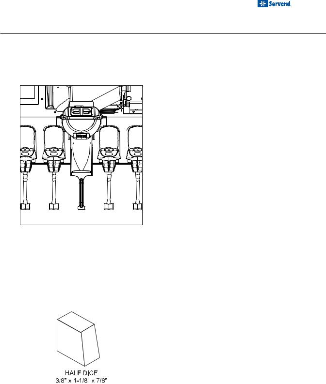
RECOMMENDED ICE TYPES
Manitowoc Half Dice Ice has been shown to give the best performance in this dispenser. Hoshizaki America, Inc., ice machines with crescent-style shape cubes are not compatible with this dispenser.
Super-cooled ice is ice that has been stored below 32o F (0o C). Super-cooled ice should be allowed to warm at room temperature for 25 to 30 minutes before emptying into the dispenser. Failure to do so may result in severe damage to the dispenser.
7

Installation and Service Manual
OPERATION
SELECTABLE ICE CONTROL BOARD
Triangle on the harness indicates pin 1 location, pin 9 location is blank.
Continuity between pin 1&2 = cubed ice
Continuity between pin 1&3 = crushed ice
9
No Pin
Pin Locations 3 2 1
8
Loading...