


 Loading...
CEV SERIES
Beverage Dispensers
Installation, Use & Care Manual
This manual is updated as new information and models are released. Visit our website for the latest manual. www.manitowocfsg.com
Leader in Ice & Beverage Dispensers
Part Number 020004000 04/12
Safety Notices
As you work on Manitowoc equipment, be sure to pay close attention to the safety notices in this manual. Disregarding the notices may lead to serious injury and/ or damage to the equipment.
Throughout this manual, you will see the following types of safety notices:
! Warning
Text in a Warning box alerts you to a potential personal injury situation. Be sure to read the Warning statement before proceeding, and work carefully.
! Caution
Text in a Caution box alerts you to a situation in which you could damage the equipment. Be sure to read the Caution statement before proceeding, and work carefully.
Procedural Notices
As you work on Manitowoc equipment, be sure to read the procedural notices in this manual. These notices supply helpful information which may assist you as you work.
Throughout this manual, you will see the following types of procedural notices:
Important
Text in an Important box provides you with information that may help you perform a procedure more efficiently. Disregarding this information will not cause damage or injury, but it may slow you down as you work.
NOTE: Text set off as a Note provides you with simple, but useful, extra information about the procedure you are performing.
Read These Before Proceeding:
! Caution
Proper installation, care and maintenance are essential for maximum performance and troublefree operation of your Manitowoc equipment. Read and understand this manual. It contains valuable care and maintenance information. If you encounter problems not covered by this manual, do not proceed, contact Manitowoc Foodservice Group. We will be happy to provide assistance.
Important
Routine adjustments and maintenance procedures outlined in this manual are not covered by the warranty.
! Warning
PERSONAL INJURY POTENTIAL
Do not operate equipment that has been misused, abused, neglected, damaged, or altered/modified from that of original manufactured specifications.
NOTE: SAVE THESE INSTRUCTIONS.
We reserve the right to make product improvements at any time. Specifications and design are subject to change without notice.

Table of Contents (continued)
Section 1
General Information
Read This Manual . . . . . . . . . . . . . . . . . . . . . . . . . . . . . . . . . . . . . . . . . . . . . . . . . |
1-1 |
Unit Inspection . . . . . . . . . . . . . . . . . . . . . . . . . . . . . . . . . . . . . . . . . . . . . . . . . . . |
1-1 |
Model Numbers. . . . . . . . . . . . . . . . . . . . . . . . . . . . . . . . . . . . . . . . . . . . . . . . . . . |
1-1 |
Accessories. . . . . . . . . . . . . . . . . . . . . . . . . . . . . . . . . . . . . . . . . . . . . . . . . . . . . . |
1-1 |
Serial Number Location . . . . . . . . . . . . . . . . . . . . . . . . . . . . . . . . . . . . . . . . . . . . |
1-2 |
Warranty Information . . . . . . . . . . . . . . . . . . . . . . . . . . . . . . . . . . . . . . . . . . . . . . |
1-2 |
Section 2
Installation Instructions
General System Overview . . . . . . . . . . . . . . . . . . . . . . . . . . . . . . . . . . . . . . . . . . |
2-1 |
Pre-installation Checklist. . . . . . . . . . . . . . . . . . . . . . . . . . . . . . . . . . . . . . . . . . . |
2-2 |
Selecting Locations . . . . . . . . . . . . . . . . . . . . . . . . . . . . . . . . . . . . . . . . . . . . . . . |
2-4 |
Placing Unit in the Operating Position . . . . . . . . . . . . . . . . . . . . . . . . . . . . |
2-4 |
Footprints . . . . . . . . . . . . . . . . . . . . . . . . . . . . . . . . . . . . . . . . . . . . . . . . . . . . . . . |
2-6 |
CEV30 Footprint . . . . . . . . . . . . . . . . . . . . . . . . . . . . . . . . . . . . . . . . . . . . . |
2-6 |
CEV40 Footprint . . . . . . . . . . . . . . . . . . . . . . . . . . . . . . . . . . . . . . . . . . . . . |
2-7 |
Location. . . . . . . . . . . . . . . . . . . . . . . . . . . . . . . . . . . . . . . . . . . . . . . . . . . . . . . . . |
2-8 |
Electrical . . . . . . . . . . . . . . . . . . . . . . . . . . . . . . . . . . . . . . . . . . . . . . . . . . . . . . . . |
2-9 |
General . . . . . . . . . . . . . . . . . . . . . . . . . . . . . . . . . . . . . . . . . . . . . . . . . . . . |
2-9 |
Minimum Circuit Ampacity . . . . . . . . . . . . . . . . . . . . . . . . . . . . . . . . . . . . . |
2-9 |
Electrical Requirements . . . . . . . . . . . . . . . . . . . . . . . . . . . . . . . . . . . . . . . |
2-9 |
Voltage . . . . . . . . . . . . . . . . . . . . . . . . . . . . . . . . . . . . . . . . . . . . . . . . . . . . |
2-9 |
Minimum Circuit Amperage Chart . . . . . . . . . . . . . . . . . . . . . . . . . . . . . . . . |
2-9 |
Refrigerant . . . . . . . . . . . . . . . . . . . . . . . . . . . . . . . . . . . . . . . . . . . . . . . . . |
2-9 |
Grounding Instructions . . . . . . . . . . . . . . . . . . . . . . . . . . . . . . . . . . . . . . . . . . . . |
2-9 |
Unit Installation. . . . . . . . . . . . . . . . . . . . . . . . . . . . . . . . . . . . . . . . . . . . . . . . . . . |
2-11 |
Counter Sealing . . . . . . . . . . . . . . . . . . . . . . . . . . . . . . . . . . . . . . . . . . . . . |
2-11 |
Filling the water tank . . . . . . . . . . . . . . . . . . . . . . . . . . . . . . . . . . . . . . . . . . |
2-11 |
Refrigeration System Start . . . . . . . . . . . . . . . . . . . . . . . . . . . . . . . . . . . . . |
2-12 |
Incoming Water Supply requirements . . . . . . . . . . . . . . . . . . . . . . . . . . . . . |
2-12 |
Connecting the Drain Pan Hose . . . . . . . . . . . . . . . . . . . . . . . . . . . . . . . . . |
2-12 |
Carbonator Tank Purge Tube Routing . . . . . . . . . . . . . . . . . . . . . . . . . . . . |
2-13 |
Connecting Water & Syrup Supply Line(s) . . . . . . . . . . . . . . . . . . . . . . . . . |
2-14 |
Premix Pressures . . . . . . . . . . . . . . . . . . . . . . . . . . . . . . . . . . . . . . . . . . . . |
2-14 |
Plumbing Diagrams . . . . . . . . . . . . . . . . . . . . . . . . . . . . . . . . . . . . . . . . . . . |
2-15 |
Carbonated/non-carbonated Conversion Instructions . . . . . . . . . . . . . . . . |
2-17 |
CEV Bag-in-Box (BIB) Start-up . . . . . . . . . . . . . . . . . . . . . . . . . . . . . . . . . . |
2-17 |
Install Labels . . . . . . . . . . . . . . . . . . . . . . . . . . . . . . . . . . . . . . . . . . . . . . . . |
2-17 |
ADA Key Pads . . . . . . . . . . . . . . . . . . . . . . . . . . . . . . . . . . . . . . . . . . . . . . |
2-18 |
Part Number 020004000 04/12 |
i |

Table of Contents (continued)
Clean Up . . . . . . . . . . . . . . . . . . . . . . . . . . . . . . . . . . . . . . . . . . . . . . . . . . . |
2-19 |
Section 3
Operation
Component Identification . . . . . . . . . . . . . . . . . . . . . . . . . . . . . . . . . . . . . . . . . . . |
3-1 |
Sequence of Operation . . . . . . . . . . . . . . . . . . . . . . . . . . . . . . . . . . . . . . . . . . . . . |
3-1 |
Unit Inspection . . . . . . . . . . . . . . . . . . . . . . . . . . . . . . . . . . . . . . . . . . . . . . . |
3-1 |
Beverage Valves . . . . . . . . . . . . . . . . . . . . . . . . . . . . . . . . . . . . . . . . . . . . . |
3-2 |
Carbonated Water . . . . . . . . . . . . . . . . . . . . . . . . . . . . . . . . . . . . . . . . . . . . |
3-3 |
Syrup Delivery System . . . . . . . . . . . . . . . . . . . . . . . . . . . . . . . . . . . . . . . . |
3-3 |
Back Room Package . . . . . . . . . . . . . . . . . . . . . . . . . . . . . . . . . . . . . . . . . . |
3-3 |
Figal System . . . . . . . . . . . . . . . . . . . . . . . . . . . . . . . . . . . . . . . . . . . . . . . . |
3-4 |
Figal Tanks . . . . . . . . . . . . . . . . . . . . . . . . . . . . . . . . . . . . . . . . . . . . . . . . . |
3-4 |
Racking . . . . . . . . . . . . . . . . . . . . . . . . . . . . . . . . . . . . . . . . . . . . . . . . . . . . |
3-4 |
B-I-B . . . . . . . . . . . . . . . . . . . . . . . . . . . . . . . . . . . . . . . . . . . . . . . . . . . . . . |
3-4 |
Pumps . . . . . . . . . . . . . . . . . . . . . . . . . . . . . . . . . . . . . . . . . . . . . . . . . . . . . |
3-4 |
Auto Bag Selectors . . . . . . . . . . . . . . . . . . . . . . . . . . . . . . . . . . . . . . . . . . . |
3-4 |
Operation Checks and Adjustments . . . . . . . . . . . . . . . . . . . . . . . . . . . . . . . . . . |
3-5 |
Electronic Ice and & Carbonation Control . . . . . . . . . . . . . . . . . . . . . . . . . . |
3-5 |
Section 4
Maintenance
Cleaning . . . . . . . . . . . . . . . . . . . . . . . . . . . . . . . . . . . . . . . . . . . . . . . . . . . . . . . . . |
4-1 |
Daily Cleaning . . . . . . . . . . . . . . . . . . . . . . . . . . . . . . . . . . . . . . . . . . . . . . . |
4-1 |
Water Bath . . . . . . . . . . . . . . . . . . . . . . . . . . . . . . . . . . . . . . . . . . . . . . . . . . |
4-2 |
Cleaning Checklist . . . . . . . . . . . . . . . . . . . . . . . . . . . . . . . . . . . . . . . . . . . . |
4-2 |
Preventive Maintenance . . . . . . . . . . . . . . . . . . . . . . . . . . . . . . . . . . . . . . . |
4-2 |
Sanitizing . . . . . . . . . . . . . . . . . . . . . . . . . . . . . . . . . . . . . . . . . . . . . . . . . . . . . . . . |
4-2 |
Beverage System Cleaning . . . . . . . . . . . . . . . . . . . . . . . . . . . . . . . . . . . . . |
4-2 |
Bag-In-Box System Sanitation . . . . . . . . . . . . . . . . . . . . . . . . . . . . . . . . . . . |
4-2 |
Figal Beverage System . . . . . . . . . . . . . . . . . . . . . . . . . . . . . . . . . . . . . . . . |
4-3 |
Shipping, Storage and Relocation. . . . . . . . . . . . . . . . . . . . . . . . . . . . . . . . . . . . |
4-4 |
Section 5
Before Calling for Service
Checklist . . . . . . . . . . . . . . . . . . . . . . . . . . . . . . . . . . . . . . . . . . . . . . . . . . . . . . . . |
5-1 |
Drink Troubleshooting . . . . . . . . . . . . . . . . . . . . . . . . . . . . . . . . . . . . . . . . . |
5-1 |
Pump Troubleshooting . . . . . . . . . . . . . . . . . . . . . . . . . . . . . . . . . . . . . . . . . . . . . |
5-2 |
ii |
Part Number 020004000 04/12 |
Section 1
General Information
Read This Manual
Manitowoc Beverage Equipment (MBE) developed this manual as a reference guide for the owner/operator and installer of this equipment. Please read this manual before installation or operation of the machine. A qualified service technician must perform installation and start-up of this equipment, consult Section 5 within this manual for service assistance.
If you cannot correct the service problem, call your MBE Service Agent or Distributor. Always have your model and serial number available when you call.
Your Service Agent ____________________________
Service Agent Telephone Number _________________
Your Local MBE Distributor ______________________
Distributor Telephone Number ____________________
Model Number _______________________________
Serial Number ________________________________
Installation Date ______________________________
Unit Inspection
Thoroughly inspect the unit upon delivery. Immediately report any damage that occurred during transportation to the delivery carrier. Request a written inspection report from a claims inspector to document any necessary claim.
! Warning
PERSONAL INJURY POTENTIAL
Do not operate equipment that has been misused, abused, neglected, damaged, or altered/modified from that of original manufactured specifications.
Model Numbers
This manual covers the following models:
Beverage Dispensers
CEVe-30, CEVe-40, CEVi-30, CEVi-40, CEVj-30
Accessories
If you are top mounting your dispenser with a cuber, you will require a lid for the manual fill area at the top, front of the dispenser.
If you ordered a dispenser and a cuber at the same time, the manual fill lid was included with the unit. The manual fill lid can be ordered from your local distributor.
Part Number 020004000 04/12 |
1-1 |

General Information |
Section 1 |
|
|
Serial Number Location
This number is required when requesting information from your local distributor. The serial number is listed on the SERIAL NUMBER DECAL affixed to the dispenser.
Label
Serial Number Location
Warranty Information
Consult your local MBE Distributor for terms and conditions of your warranty. Your warranty specifically excludes all beverage valve brixing, general adjustments, cleaning, accessories and related servicing.
Your warranty card must be returned to MBE to activate the warranty on this equipment. If a warranty card is not returned, the warranty period can begin when the equipment leaves the MBE factory.
No equipment may be returned to MBE without a written Return Materials Authorization (RMA). Equipment returned without an RMA will be refused at MBE’s dock and returned to the sender at the sender’s expense.
Please contact your local MBE distributor for return procedures.
1-2 |
Part Number 020004000 04/12 |

Section 2
Installation Instructions
General System Overview
These instructions are provided to assist the qualified installer. Contact your Manitowoc Beverage Equipment Service Agent or call Manitowoc Beverage Equipment for information regarding start-up services.
Important
Failure to follow these installation guidelines may affect warranty coverage.
TO THE CARB TANK
Typical CEV Series Internal Carbonation Beverage Dispensing System
|
|
SYRUP |
|
|
|
|
|
|
|
BIB |
|
|
|
|
|
Syrup Pump |
|
|
|
CARBONATED WATER |
90- |
|
-Box |
|
|
1800 |
100 |
|
|
|
|
|
|
In |
|
Tap Water |
|
|
|
- |
|
NON-CARBONATED WATER |
|
60 |
Bag |
|
|
|
|
|
|
Syrup |
|
|
|
|
|
|
Carton |
|
|
CO2 |
CO2 |
SYRUP |
|
|
|
Cylinder |
|
|
|
Tap Water |
Carbonator |
|
|
|
|
Tank |
|
|
|
||
|
|
|
|
||
|
|
|
|
|
|
|
|
2 |
|
|
|
|
|
CO |
|
|
|
Typical CEV External Carbonation (Ambient) Beverage Dispensing System
Part Number 020004000 04/12 |
2-1 |

Installation Instructions |
Section 2 |
|
|
Pre-installation Checklist
When installing any system, first make sure the major components are available. Generally the major components necessary for an installation are:
Pre-mix System: |
Post Mix System: |
CO2 regulator set
Product connectors for Figal tank
Gas connectors for Figal tank
Beverage dispenser
Beverage tubing
CO2 tank
Figal beverage tanks
Stepless (Oetiker) clamps
Chain for CO2 tank
B-I-B System also:
B-I-B connectors
B-I-B regulator set
B-I-B rack
B-I-B syrup boxes
CO2 regulator set
Beverage dispenser
Beverage tubing
CO2 tank
Carbonator
Stepless (Oetiker) clamps
Chain for CO2 tank
Figal system also:
Syrup connectors for Figal tank
Gas connectors for Figal tank
Figal syrup tanks
2-2 |
Part Number 020004000 04/12 |

Section 2 |
|
|
Installation Instructions |
|||
|
|
|
|
|
|
|
Bulk Syrup System also: |
Also consider the location of the following items |
|||||
|
|
|
before installation: |
|||
|
|
Syrup connectors for Bulk tank |
|
|
Water line |
|
|
|
|
|
|||
|
|
|
|
|||
|
|
Gas connectors for Bulk tank |
|
|
||
|
|
|||||
|
|
|
|
Drain |
||
|
|
|
|
|||
|
|
|
|
|||
|
|
|
|
|||
|
|
Bulk syrup tanks |
|
|
||
|
|
|||||
|
|
|
|
Power outlet |
||
|
|
|
|
|||
|
|
|
|
|||
|
|
|
|
|||
|
|
|
|
|
||
Double Check: |
||||||
|
|
|
||||
|
|
|
||||
|
|
Do you have enough space to install the |
|
|
Heating and air conditioning ducts |
|
|
|
|
|
|
||
|
|
|
|
|
||
|
|
dispenser or a dispenser and top mounted |
|
|
|
|
|
|
cuber? |
|
|
|
|
|
|
|
|
|
||
|
|
Does top mounted cuber (if utilized) have a |
|
|
|
|
|
|
|
|
|
||
|
|
minimum of 6 inches (15.3 cm) clearance on all |
|
|
|
|
|
|
sides? |
|
|
|
|
|
|
|
|
|
||
|
|
Is the countertop level? |
|
|
|
|
|
|
|
|
|
||
|
|
Can the countertop support the weight of the |
|
|
|
|
|
|
|
|
|
||
|
|
|
|
|
||
|
|
dispenser, or the dispenser/cuber combination |
|
|
|
|
|
|
plus the weight of the stored ice? |
|
|
|
|
|
|
|
|
|
||
Part Number 020004000 04/12 |
2-3 |
Installation Instructions |
Section 2 |
|
|
Selecting Locations
The CEV may be island-mounted or installed on a front or rear counter. Locate the CEV so the following requirements are satisfied: CEV is for indoor use only and must NOT be placed in an area where a water jet or similar high pressure sprayer could be used.
1.CEV must be installed near a properly grounded electrical outlet with proper electrical requirements fused at proper amperage or circuit connected through an equivalent HACR circuit breaker with ELCB (GFCI). REFER TO UNIT NAMEPLATE FOR THE REQUIRED POWER CIRCUIT OPERATING VOLTAGE. HERTZ AND THE MINIMUM CIRCUIT AMPACITY OF THE CEV. No other electrical equipment should be connected to this circuit. ALL ELECTRICAL WIRING MUST CONFORM TO NATIONAL AND LOCAL ELECTRICAL CODES. MAIN PLUG MUST BE ACCESSIBLE FOR DISCONNECTION.
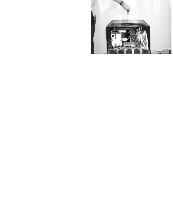
2.A minimum of 15-inches clearance must be maintained above the CEV to the nearest obstruction (shelf, cupboard, ceiling, etc.) and 4- inches clearance between the back of the CEV and the wall and 12-inches between each side and the wall. CEV has a top air outlet and is to remain free of all objects. Do not place anything on top of the CEV. The rear grill of the CEV must be unobstructed to allow air to enter the hood. This will also allow access to the condenser filter for cleaning.
3.If a permanent drain is to be used place CEV close to a permanent drain in order to route the drain pan hose to the permanent drain. Water tank overflow hose goes into the drain pan.
PLACING UNIT IN THE OPERATING POSITION
The CEV must be level horizontally from right to left and front to rear. CEV inlet supply lines, power cord, and drain pan hose must either be routed out of the CEV base rear access hole, or through a hole cut in the countertop under the CEV Unit. Proceed to applicable installation procedure. Two plastic tubing brackets are mounted under the CEV to hold the lines in place. The rear access cover may be removed, turned and installed to provide a brace to prevent the CEV from being pushed flat against the wall.Dimensions
Island Mount
ABOVE: How to Remove the Bonnet
Place the CEV in location on the countertop flush with the countertop edge. Mark CEV’s center line on the edge of the countertop, then move the CEV to one side. Starting at the center line mark on the edge of the countertop, measure back 12-inches for the location of a hole at least 4-inches to be cut into the countertop. Cut at least a 4 inch hole in the countertop where indicated. Place the CEV in position over the hole. Route the inlet supply lines, power cord, carbonator tank purge tube and drain pan hose down through the hole in the countertop.Install the line outlet plug, provided with the CEV in the base back access hole. The area around the inlet supply lines at the flanged hole behind the front access panel must be closed and sealed.
Counter Mount
Place the CEV in location on the countertop. Route CEV inlet supply lines, power cord, carbonator tank purge tube and drain pan hose out of the base back access hole. Area around inlet supply lines at flanged hole behind front access panel must be closed and sealed.
2-4 |
Part Number 020004000 04/12 |
Section 2 |
Installation Instructions |
|
|
Counter Electric Dispenser Dimensions
* C = Valve height using Flomatic Valves.
A |
|
|
|
|
|
|
|
|
|
|
|
|
|
|
|
H |
|
|
|
|
|
C |
|
|
|
|
|
|
|
|
|
|
D |
|
|
|
|
|
|
|
B |
|
|
|
E |
|
|
I |
|
|
|
|
|
|
F |
|
|
|
|
|
|
|
|
|
G |
|
|
|
|
MODEL |
A |
B |
C* |
D |
E |
F |
G |
H |
I |
CEV-30 |
29.88" |
20.50" |
11.76" |
4.44" |
N/A |
N/A |
25.75" |
17.00" |
17.50" |
|
(75.9 cm) |
(52.7 cm) |
(29.8 cm) |
(11.3 cm) |
|
|
(65.4 cm) |
(43.1 cm) |
(44.4 cm) |
CEV-40 |
29.88" |
26.00" |
11.76" |
4.44" |
N/A |
N/A |
25.75" |
17.00" |
23.00" |
|
(75.9 cm) |
(66.0 cm) |
(29.8 cm) |
(11.3 cm) |
|
|
(65.4 cm) |
(43.1 cm) |
(58.4 cm) |
! Caution
Cutting the countertop may decrease its strength. Counter should be braced to support the dispenser countertop weight plus ice storage capacity and weight of icemaker, if applicable.
Part Number 020004000 04/12 |
2-5 |

Installation Instructions |
Section 2 |
|
|
Footprints
CEV30 FOOTPRINT
! Caution
Cutting the countertop may decrease its strength. Counter should be braced to support the dispenser countertop weight plus ice storage capacity and weight of icemaker, if applicable.
2-6 |
Part Number 020004000 04/12 |

Section 2 |
Installation Instructions |
|
|
CEV40 FOOTPRINT
! |
Caution |
Cutting the countertop may decrease its strength. Counter should be braced to support the dispenser countertop weight plus ice storage capacity and weight of icemaker, if applicable.
Part Number 020004000 04/12 |
2-7 |
Loading...