


MD-200
Table of contents
 Loading...
MD-200 & 250
Quiznos™ Beverage/Ice Dispenser
INSTALLATION & SERVICE GUIDE
Part Number 5030765
Manitowoc Beverage Equipment
2100 Future Drive Sellersburg, IN 47172-1868
Tel: 812.246.7000, 800.367.4233 Fax: 812.246.9922
www.manitowocbeverage.com
In accordance with our policy of continuous product development and
improvement, this information is subject to change at any time without notice.
October 19, 2006 REV6


FOREWORD
Manitowoc Beverage Equipment (MBE) developed this manual as a reference guide for the owner/
operator , service agent, and installer of this equipment. Please read this manual before installation
or operation of the machine. A qualified service technician should perform installation and startup of this equipment, consult the Troubleshooting Guide within this manual for service assistance.
If you cannot correct the service problem, call your MBE Service Agent or Distributor. Always have your model and
serial number available when you call.
Your Service Agent___________________________________________________________________
Service Agent Telephone Number ______________________________________________________
Your Local MBE Distributor ___________________________________________________________
Distributor Telephone Number _________________________________________________________
Model Number ______________________________________________________________________
Serial Number _______________________________________________________________________
Installation Date _____________________________________________________________________
UNPACKING AND INSPECTION
Note: The unit was thoroughly inspected before leaving the factory. Any damage or irregularities should
be noted at the time of delivery.
WARRANTY INFORMATION
Consult your local MBE Distributor for terms and conditions of your warranty. Your warranty specifically
excludes all beverage valve brixing, general adjustments, cleaning, accessories and related servicing.
Your warranty card must be returned to Manitowoc Beverage Equipment to activate the warranty on this
equipment. If a warranty card is not returned, the warranty period can begin when the equipment leaves
the MBE factory .
No equipment may be returned to Manitowoc Beverage Equipment without a written Return Goods
Authorization (RGA). Equipment returned without an RGA will be refused by MBE’s Receiving Department
and returned to the sender at the sender’s expense.
Please contact your local MBE distributor for return procedures.

TABLE OF CONTENTS
FOREWORD ........................................................................................................ 3
UNPACKING AND INSPECTION ........................................................................3
WARRANTY INFORMA TION ............................................................................... 3
SAFETY ...............................................................................................................6
IMPORT ANT SAFETY INSTRUCTIONS ............................................................................. 6
CARBON DIOXIDE WARNING........................................................................................... 6
QUALIFIED SERVICE PERSONNEL .................................................................................. 6
SHIPPING , STORAGE, AND RELOCATION....................................................................... 6
ADDITIONAL WARNINGS ................................................................................................. 6
GROUNDING IN STRUCTIONS ......................................................................................... 7
INSTALLATION.................................................................................................... 8
PRE-INSTALLA TION CHECK LIST .................................................................................... 8
LEGS ................................................................................................................................8
INTERNAL CARBONA TION ............................................................................................... 8
COLD CARB BAG-IN-BOX (B-I-B) SYSTEM ....................................................................... 9
COLD CARB SYSTEM PRESSURES ................................................................................. 9
UNIT INST ALLATION .......................................................................................................10
DRAINAGE OPTIONS ......................................................................................................10
CARB TANK PURGE TUBE ROUTING .............................................................................11
TOP MOUNTED ICEMAKER REQUIREMENTS .................................................................12
BAFFLE FOR MANITOWOC™ CUBERS ..........................................................................13
BAFFLE FOR "Q" SERIES ICE MACHINES......................................................................13
MANUAL FILL LID FOR DISPENSERS MOUNTED WITH A CUBER.................................13
PLUMBING DIAGRAM LOCA TION & FLEX MANIFOLD ...................................................14
DIAGRAM ........................................................................................................................14
OPERATION ...................................................................................................... 15
UNIT INSPECTION ...........................................................................................................15
ICE STORAGE AND DISPENSING ...................................................................................15
COLD PLA TE BEVERAGE COOLING ...............................................................................15
ROCKING CHUTE ICE DISPENSING ................................................................................15
BEVERAGE V ALVES ........................................................................................................16
POST-MIX BEVERAGE DISPENSERS.............................................................................16
BACK ROOM PACKAGE ..................................................................................................17
BAG-IN-BOX SYSTEM .....................................................................................................17
COUNTERTOP MEASUREMENTS....................................................................................18
SPECIFICA TIONS ............................................................................................................19
115V/220V NON ADJUST ABLE AGITA TION TIMER ..........................................................20
ICE CHUTE SEQUENCE OF OPERA TION .........................................................................20

Installation and Service Manual
TABLE OF CONTENTS
USER MAINTENANCE ......................................................................................21
HOW TO DISASSEMBLE FOR CLEANING OR MAINTENANCE .......................................21
DAIL Y CLEANING.............................................................................................................24
MONTHL Y CLEANING ......................................................................................................25
BEVERAGE SYSTEM CLEANING .....................................................................................26
BAG-IN-BOX SYSTEM .....................................................................................................26
PREVENT ATIVE MAINTENANCE......................................................................................27
EXPLODED VIEWS, PARTS & DIAGRAMS ..................................................... 28
MD-200 & 250 QUIZNOS™ UNIT EXPLODED VIEW .........................................................28
MD-200 & 250 QUIZNOS™ UNIT PARTS LIST .................................................................29
MD-200 QUIZNOS™ MERCHANDISER .............................................................................30
MD-250 QUIZNOS™ MERCHANDISER .............................................................................31
WIRING MD-200 & 250 QUIZNOS™ UNIT 115V...............................................................32
TROUBLESHOOTING.......................................................................................33
PUMP...............................................................................................................................33
DRINKS............................................................................................................................34
DRINKS............................................................................................................................35
LIQUID LEVEL CONTROL................................................................................................36
INDEX ................................................................................................................ 39
5

SAFETY
IMPORTANT SAFETY INSTRUCTIONS
Carefully read all safety messages in this manual. Learn how to operate the MD unit properly . Do not
allow anyone to operate the unit without proper training and keep it in proper working condition.
Unauthorized modifications to the MD may impair function and/or safety and affect the life of the unit.
CARBON DIOXIDE WARNING
DANGER: Carbon Dioxide (CO2) displaces oxygen. Exposure to a high concentration of CO2 gas causes
tremors, which are followed rapidly by loss of consciousness and suffocation. If a CO2 gas leak is
suspected, particularly in a small area, immediately ventilate the area before repairing the leak. CO2 lines
and pumps should not be installed in an enclosed space. An enclosed space can be a cooler or small
room or closet. This may include convenience stores with glass door self serve coolers. If you suspect CO
may build up in an area, venting of the B-I-B pumps and / or CO2 monitors should be utilized.
QUALIFIED SERVICE PERSONNEL
WARNING: Only trained and certified electrical and plumbing technicians should service this unit. All
wiring and plumbing must conform to national and local codes.
2
SHIPPING, STORAGE, AND RELOCATION
CAUTION: Before shipping, storing, or relocating this unit, syrup systems must be sanitized. After
sanitizing, all liquids (sanitizing solution and water) must be purged from the unit. A freezing environment causes residual sanitizing solution or water remaining inside the unit to freeze, resulting in
damage to internal components.
ADDITIONAL WARNINGS
Installation and start-up of this equipment should be done by a qualified service technician. Operation,
maintenance, and cleaning information in this manual are provided for the user/operator of the equipment.
Save these instructions.

Installation and Service Manual
SAFETY
GROUNDING IN STRUCTIONS
WARNING: Risk of electrical shock. Connect to a properly grounded outlet only .
This appliance must be grounded. In the event of malfunction or breakdown, grounding provides a
path of least resistance for electric current to reduce the risk of electric shock. This appliance is
equipped with a cord having an equipment-grounding conductor and a grounding plug. The plug
must be plugged into an appropriate outlet that is properly installed and grounded in accordance
with all local codes and ordinances.
DANGER – Improper connection of the equipment-grounding conductor can result in a risk of electric shock. The conductor with insulation having an outer surface that is green with or without yellow
stripes is the equipment grounding conductor. If repair or replacement of the cord or plug is necessary , do not connect the equipment-grounding conductor to a live terminal. Check with a qualified
electrician or serviceman if the grounding instructions are not completely understood, or if in doubt
as to whether the appliance is properly grounded. Do not modify the plug provided with the appliance – if it will not fit the outlet, have a proper outlet installed by a qualified electrician.
WARNING – When using electric appliances, basic precautions should always be followed, including the following:
a) Read all the instructions before using the appliance.
b) T o reduce he risk of injury , close supervision is necessary when an appliance is used near
children.
c) Do not contact moving parts.
d) Only use attachments recommended or sold by the manufacturer .
e) Do not use outdoors.
f) For a cord-connected appliance, the following shall be included:
• Do not unplug by pulling on cord. T o unplug, grasp the plug, not the cord.
• Unplug from outlet when not in use and before servicing or cleaning.
• Do not operate any appliance with a damaged cord or plug, or after the appliance
malfunctions or is dropped or damaged in any manner . Return appliance to the nearest
authorized service facility for examination, repair , or electrical or mechanical adjustment.
g) For a permanently connected appliance – Turn the power switch to the of f position when
the appliance is not in use and before servicing or cleaning.
h) For an appliance with a replaceable lamp – always unplug before replacing the lamp.
Replace the bulb with the same type.
i) For a grounded appliance – Connect to a properly grounded outlet only. See Grounding
Instructions.
SAVE THESE INSTRUCTIONS
7
Installation and Service Manual
INSTALLATION
PRE-INSTALLATION CHECK LIST
Do you have enough space to install the dispenser or a dispenser and top mounted cuber?
Does the top mounted cuber (if utilized) have
a minimum of 6 inches (15.3) cm) clearance
on all sides?
Is the countertop level?
Can the countertop support the weight of the
dispenser, or the dispenser/cuber combination
plus the weight of the stored ice?
Also consider the location of the following items before
installation:
• Water line
• Drain
• Power outlet
• Heating and air conditioning ducts
LEGS
It is recommended if an icemaker is installed on top of
the dispenser, legs should not be installed.
Legs are optional equipment with most Servend dispensers. Standard legs are four-inch (10.2 cm) tall painted
steel legs.
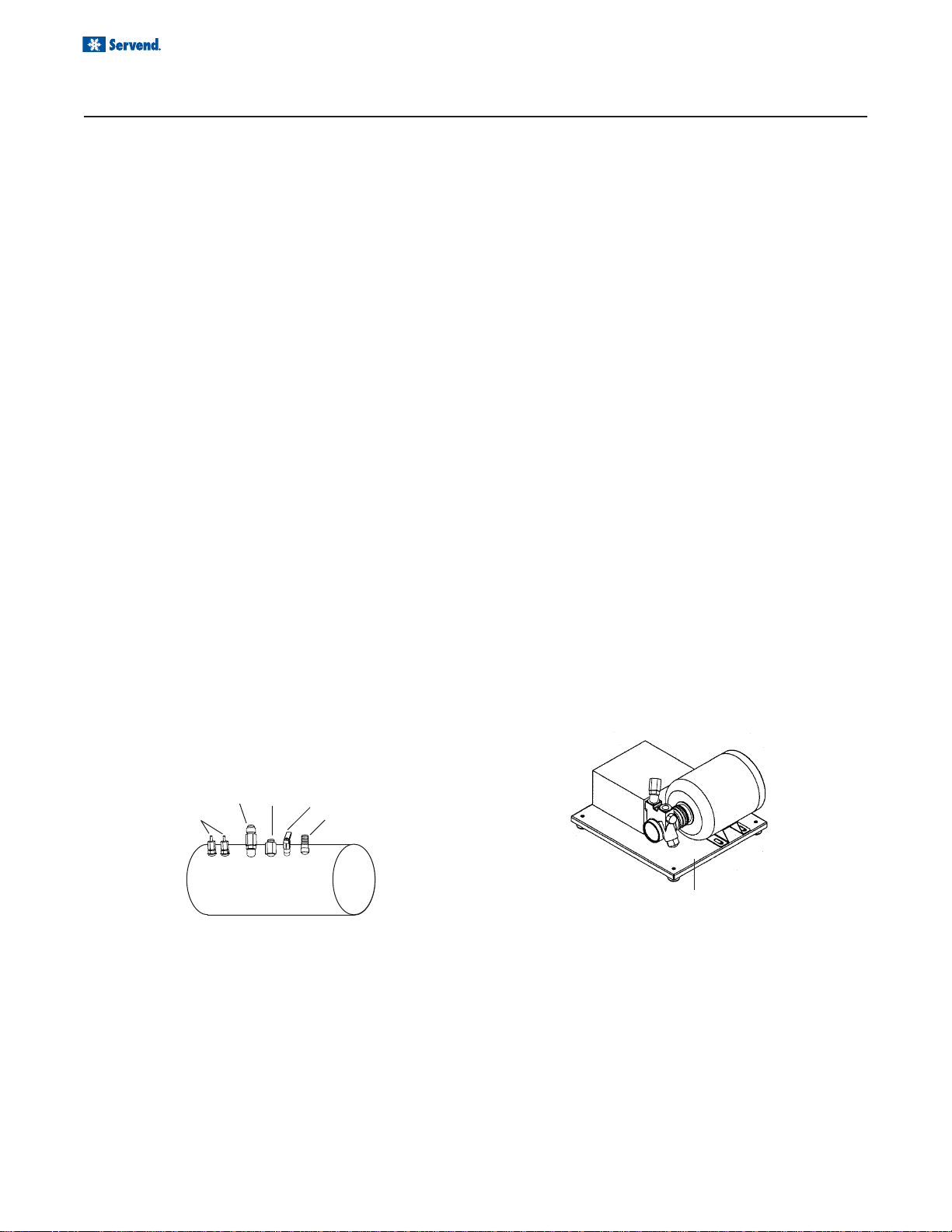
INTERNAL CARBONATION
The carbonator has two inlets and one outlet connection, as well as a relief valve and two conductivity probes.
The water inlet is a 3/8" flared fitting. The carbonator will
be pre-plumbed as it leaves the factory. If the carbonator needs to be serviced or if the fittings need to be
replaced, make sure a nylon washer is used inside the
swivel fittings to prevent leaks.
The conductivity probes are used to control the level of
water inside the carbonator tank. The red probe, or the
“high” probe, is the shorter of the two. When the level of
the water reaches the bottom of the red probe, the pump
shuts off. The black, or “low” probe activates the pump
Inlet
2
Pressure
Relief Valve
Carbonated
Water Outlet
Electronic
Probes
Water Inlet
CO
When installing legs on a MD Series dispenser, leg
braces should be used. These are metal braces fitting
side to side under the dispenser that reinforce the leg
attachment area.
The pump motor and electrical box are mounted together on a single platform. The pump is a standard
125 GPH Procon pump. The flared fittings accept the
same swivel/ barb scheme used on the carbonator
water connections. The pump outlet is a double check
valve topped with a 3/8" flared fitting. T eflon t ape or some
other means of sealing must be used on the fittings to
prevent leaks. Also, water enters the pump from the
water source on the side that has the filter.
when the water level inside the tank goes below the bottom tip of the probe. Both probes are wired to the electronic liquid level control, which is a circuit board mounted
inside the electrical box. Removing the cover of the electrical box will grant access to the circuit board. As the
control receives a signal from the conductivity probes, it
activates the pump motor, which will pump water into
the carbonator until the water reaches the high probe.
8
Carbonator Pump Deck
(Power Supply)
Installation Notes:
• Pump Decks for internal carb units must be
within 6 feet of unit.
• Installation of a carbonator any further away
than the recomended distance is at installer/
owner's risk. Known issues can include, but is
not limited to poor carbonation and/or erratic
carbonation.
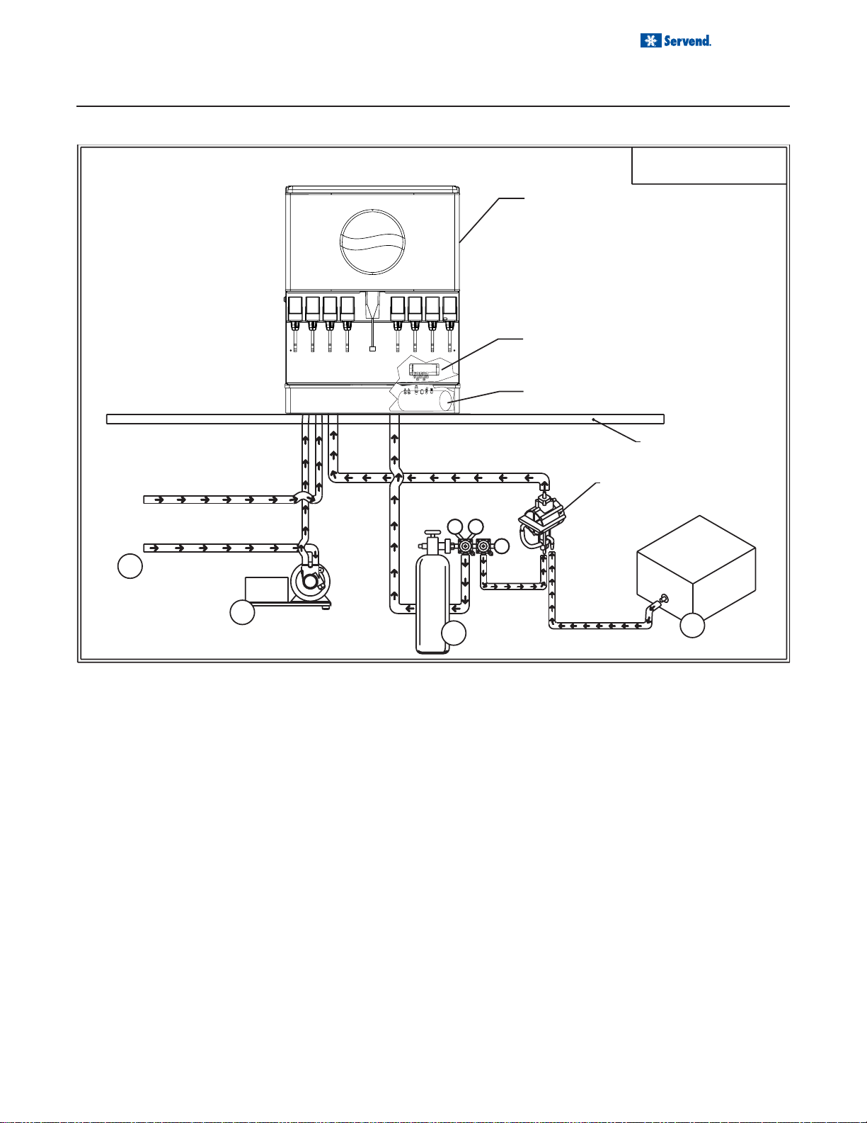
COLD CARB BAG-IN-BOX (B-I-B) SYSTEM
Quiznos
Internal Carbonation
Beverage Dispensing System
TM
MD-250
INSTALLATION
Installation and Service Manual
NOTE:
This is a simplified schematic to
show the basic operation of the
beverage system.
Dispenser
Carbonated/Non-carbonated
Beverage Manifold
Carbonator Tank
Countertop
SYRUP
BIB
Syrup Pump
SYRUP
Bag-In-Box
4
Syrup
Carton
Dwg#: 5010301-0
1
Tap Water
Tap Water
75
1800
2
CO
3
Cylinder
2
CO
2
60
CO
2
COLD CARB SYSTEM PRESSURES
1. Incoming tap water should be at a minimum pressure of 40 psi and a maximum of 55psi.
2. BIB pressure gauge set for 60 psi.
NOTE: If incoming water pressure is under 40 psi, a water booster is recommended. If incoming water pressure is
over 55 psi, a water regulating valve is required.
3. Carbonator Pressure gauge:
• Cold Carbonation set for 75 psi.
9

Installation and Service Manual
INSTALLATION
UNIT INSTALLATION
1. Place the dispenser in the desired location.
2. Run the beverage lines and water lines(make sure
to install the water connections to the proper inlets.
Connection “A” comes from the procon pump and is
your carbonated water supply and Connection “B” is
your plain water supply . (Refer to plumbing diagrams.)
3. Install drain plumbing and insulate.
4. Set flexible manifold for correct drink settings.
NOTE: The manifold is preset for the far right
valve to be a non-carbonated beverage.
DRAINAGE OPTIONS
The drains for MD Series connects to the drain pan.
5. Turn water supply on to the dispenser . Water pressure should be between 40 and 55 psi.If not inbetween those pressures proper measures must
be taken to regulate them to correct settings.
6. Turn CO2 supply on to the dispenser. Each cold carb
pump deck is furnished with a fixed regulator set at
75 psi. Ambient units need to be set between 90
and 100 psi.
7. Fill bin with ice.
8. Connect power supply.
9. Brix beverage valves.
10. Meet all code requirements.
Option One
Drainage through the bottom of the unit:
Radiator clamp
90 elbow fitting
Radiator clamp
Flexible tubing
Option Tw o
Drainage through the back of the unit:
Straight fitting
Radiator clamp
Flexible tubing
10
Holes for
beverage
lines
Holes for
drain pan
drain
B
INSTALLATION
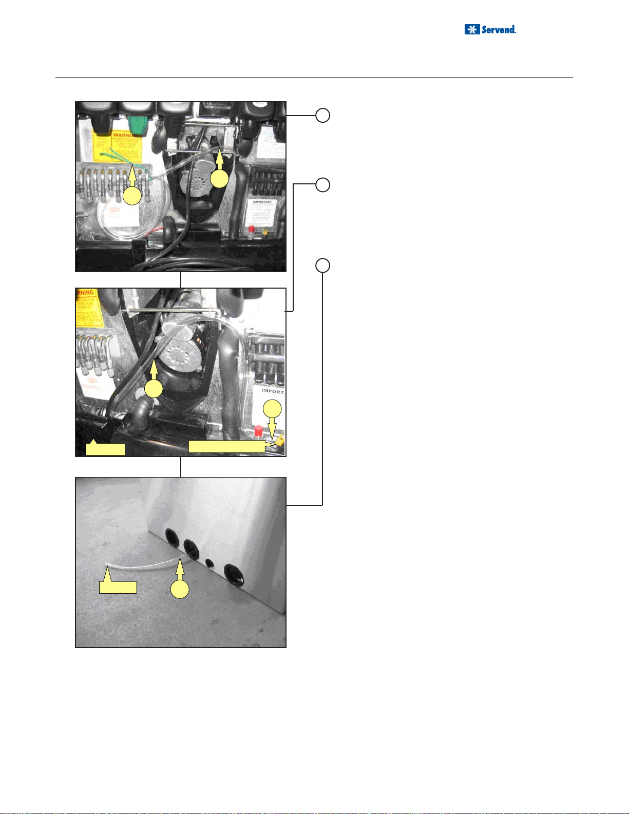
CARB TANK PURGE TUBE ROUTING
1. During installation of unit the carbonator tank purge
tube (A) must be properly routed to a drain. Once
the splash panel has been removed from unit remove twist tie (B) that holds carbonator tank purge
tube.
A
2. Route carbonator tank purge tube (A) down front of
unit and behind drain pan. Be sure not to collapse
or kink carbonator tank purge tube during routing
from unit to drain. (C) Purge tube is connected to
the pressure relief valve on carbonator tank and must
be routed to a drain
3. The carbonator tank purge tube (A) can be routed
down through the counter top that unit has been
installed on or out the rear of unit. Then install
carbonator tank purge tube to a drain. Follow all local and national plumbing codes when routing
carbonator tank purge tube to the drain.
Installation and Service Manual
Drain Pan
To Drain
A
C
Pressure Relif Valve
A
11
Installation and Service Manual
INSTALLATION
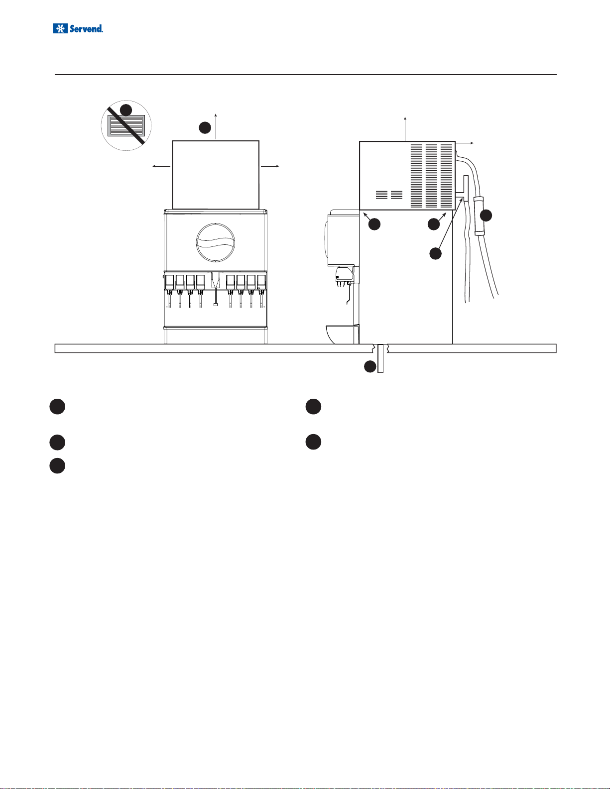
TOP MOUNTED ICEMAKER REQUIREMENTS
1
6"
(15.2 cm)
2
cuber
6" (15.2 cm)
clearance
for cuber
6"
(15.2 cm)
6" (15.2 cm)
6" (15.2 cm)
3
4
3
4
5
1 Location - Avoid placing the dispenser and/or ice
machine near heat sources such as radiators, ovens, refrigeration equipment and direct sunlight.
2 Clearances - Six inch (15.2 cm) clearance on all
sides of the icemaker is needed.
3 Front of icemaker to be flush with front of dis-
penser- The front of the icemaker should be flush
with the front of the dispenser, as shown in the
drawing above. Because the icemaker is flush with
the front of the dispenser, some icemakers may
overhang at the back of the dispenser.
4 Drains - A separate drain line is required for the
ice machine, in addition to a drain line for the ice/
beverage dispenser.
5 MD Series dispensers require an adapter kit to
install a top-mounted icemaker . Contact your lo-
cal Servend distributor for the correct adapter kit.
For full information about icemaker installation, including plumbing lines connections and electrical requirements,
see the icemaker installation manual.
12
Loading...