

Sennheiser SKM 9000,SKM 9000 Instruction Manual
Digital 9000
WSM
KA 9000 COM
Digital 9000
Instruction manual

Content
Content
Important safety instructions ..................................................5
Digital 9000 – System overview ..............................................8
EM 9046 receiver ........................................................................................ 9
Antennas and antenna boosters ............................................................. 9
SKM 9000 radio microphone/
SK 9000 bodypack transmitter ..............................................................10
L 60 charger ............................................................................................... 10
Delivery includes ..................................................................... 11
EM 9046 receiver ......................................................................................11
EM 9046 CAB cable set ............................................................................11
Antennas and antenna boosters ........................................................... 11
GZL 9000 antenna cables ........................................................................ 11
SKM 9000/SKM 9000 COM radio microphone .....................................12
Microphone heads for the SKM 9000 radio microphone ................... 12
SK 9000 bodypack transmitter .............................................................. 12
Microphones for the SK 9000 bodypack transmitter ........................12
KA 9000 COM command adapter for the
SK 9000 bodypack transmitter .............................................................. 12
CI 1-4 line/instrument cable for the
SK 9000 bodypack transmitter .............................................................. 12
B 60/B 61 battery packs ..........................................................................13
BA 60/BA 61 accupack ............................................................................13
L 60 charger ............................................................................................... 13
Product overview .................................................................... 14
EM 9046 receiver ......................................................................................14
Antennas and antenna boosters A/AB/AD9000 ...............................18
GZL 9000 antenna cable ..........................................................................19
SKM 9000/SKM 9000 COM radio microphone .....................................19
SK 9000 bodypack transmitter .............................................................. 21
KA 9000 COM command adapter for the SK 9000
bodypack transmitter ..............................................................................22
BA 60 accupack .........................................................................................23
BA 61 accupack .........................................................................................23
B 60 battery pack ......................................................................................24
B 61 battery pack ......................................................................................24
L 60 charger ............................................................................................... 25
Preparing the Digital 9000 system for use ......................... 26
Preparing the EM 9046 receiver for use .................................................27
Setting up the receiver or mounting it into a 19” rack .....................27
Connecting devices to the analog audio outputs ...............................28
Connecting devices to the digital audio outputs ................................29
Daisy chaining receivers ..........................................................................29
Connecting external word clock signals ...............................................31
Connecting receivers in a network ........................................................ 31
Connecting the receiver to the mains ...................................................32
Connecting headphones ..........................................................................33
Digital 9000 | 1

Content
Preparing the A/AB/AD 9000 antennas and/
or antenna boosters for use ..................................................................... 34
Positioning the receiving antennas ....................................................... 34
Connecting the receiving antennas/antenna boosters .....................35
Adjusting the receiving antennas/antenna boosters ....................... 35
Preparing the SKM 9000 radio microphone for use .............................35
Changing the microphone head ............................................................. 37
Preparing the SK 9000 bodypack transmitter for use .........................37
Connecting the antenna .......................................................................... 40
Connecting the KA 9000 COM command adapter ..............................40
Preparing the L 60 charger for use .........................................................41
Cascading several chargers .....................................................................41
Setting up or mounting the charger .....................................................41
Using the EM 9046 .................................................................. 43
Switching the receiver on/off ................................................................. 44
“sys”, “ch”, “live” – operating modes at a glance ................................ 45
Basic functions of the Sennheiser operating menu ...........................45
Displays of the Sennheiser operating menu .......................................46
Error and warning messages ..................................................................48
“sys” operating mode – Configuring the system ................................. 49
Overview of the “sys” menu ................................................................... 49
Main menu “System setup” ....................................................................50
Extended menu “Service setup” ............................................................ 57
“ch” operating mode – Configuring channels .......................................65
Overview of the “ch” menu ....................................................................65
Main menu “Channel setup” ................................................................... 67
Extended menu “Transmitter setup” ...................................................71
“live” operating mode – Using a configured system ...........................74
Using the SKM 9000 ................................................................ 75
Switching the SKM 9000 on/off ............................................................ 76
Activating/deactivating the automatic lock mode
(Autolock) .................................................................................................. 77
Basic functions of the Sennheiser operating menu ...........................78
Overview of the status displays .............................................................78
Overview of the menu items ..................................................................79
Using the SK 9000 ................................................................... 81
Switching the SK 9000 on/off ................................................................82
Activating/deactivating the automatic lock mode
(Autolock) .................................................................................................. 83
Basic functions of the Sennheiser operating menu ...........................84
Overview of the status displays .............................................................84
Overview of the menu items ..................................................................85
2 | Digital 9000

Content
Using the L 60 .......................................................................... 88
Cleaning and maintaining the Digital 9000 system .......... 91
If a problem occurs ... ................................................................................. 94
EM 9046 receiver .......................................................................................95
SKM 9000 radio microphone ....................................................................96
SK 9000 bodypack transmitter ...............................................................96
L 60 charger ............................................................................................... 97
Specifications.............................................................................................. 98
Manufacturer Declarations .................................................. 107
Digital 9000 | 3
Important safety instructions
Digital 9000
ME 9002
ME 9004
ME 9005
...
B 60
BA 60
B 61
BA 61
L 60
MKE 1
MKE 2
...
EM 9046 DRX
EM 9046 AAO
EM 9046 DAO
EM 9046 CAB
EM 9046 CAB
KA 9000 COM
CI 1-4
GZL 9000-A5
GZL 9000-A10
GZL 9000-A20
AD 9000
EM 9046
SK 9000
WSM
A 9000
AB 9000
SKM 9000
SKM 9000 COM

Important safety instructions
Important safety instructions
1. Read these instructions.
2. Keep these instructions. Always include these instructions when passing the apparatus on to third parties.
3. Heed all warnings.
4. Follow all instructions.
5. Do not use this apparatus near water.
6. Clean only with a dry cloth.
7. Do not block any ventilation openings. Install in accordance with the
manufacturer’s instructions.
8. Do not install near any heat sources such as radiators, heat registers,
stoves, or other apparatus (including amplifiers) that produce heat.
9. Do not defeat the safety purpose of the polarized or grounding-type
plug. A polarized plug has two blades with one wider than the other.
A grounding type plug has two blades and a third grounding prong.
The wide blade or the third prong are provided for your safety. If the
provided plug does not fit into your outlet, consult an electrician for
replacement of the obsolete outlet.
10. Protect the power supply cord from being walked on or pinched, particularly at plugs, convenience receptacles, and the point where they
exit from the apparatus.
11. Only use attachments/accessories specified by the manufacturer.
12. Use only with the cart, stand, tripod, bracket, or table specified by the
manufacturer, or sold with the apparatus.
When a cart is used, use caution when moving the cart/apparatus
combination to avoid injury from tip-over.
13. Unplug this apparatus during lightning storms or when unused for
long periods of time.
14. Refer all servicing to qualified service personnel.
Servicing is required when the apparatus has been damaged in any
way, such as power supply cord or plug is damaged, liquid has been
spilled or objects have fallen into the apparatus, when the apparatus
has been exposed to rain or moisture, does not operate normally, or
has been dropped.
15. To completely disconnect this apparatus from the AC mains, disconnect the power supply cord plug from the AC receptacle.
16. WARNING: To reduce the risk of fire or electric shock, do not expose this
apparatus to rain or moisture.
17. Do not expose this equipment to dripping or splashing and ensure that
no objects filled with liquids, such as vases, are placed on the equipment.
18. The mains plug of the power supply cord shall remain readily
accessible.
1.6.12 | Digital 9000 | 5
Important safety instructions
www
Manual
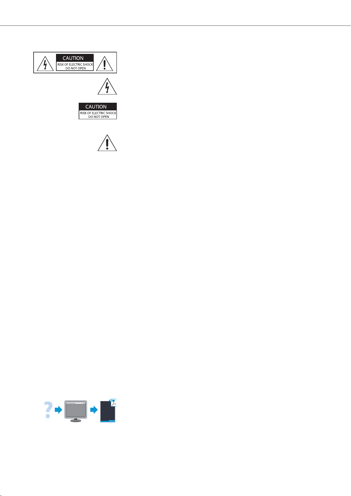
Hazard warnings on the rear of the receiver
The label shown on the left is attached to the rear of the EM 9046.
The symbols on this label have the following meaning:
Presence of uninsulated dangerous voltage within the EM 9046’s enclosure that may be of sufficient magnitude to constitute a risk of electric
shock.
Never open the EM 9046 as there is a risk of electric shock. There are no
user serviceable parts inside. Never attempt to change the modules of the
EM 9046 yourself. Always refer repairs, servicing and the change of the
modules to your authorized Sennheiser service partner.
Read and follow the safety and operating instructions contained in the
instruction manual.
Risk of fire due to overloading
Do not overload wall outlets and extension cables as this may result in fire
and electric shock.
Danger of hearing damage due to high volumes
This is a professional receiver. Commercial use is subject to the rules and
regulations of the trade association responsible. Sennheiser, as the manufacturer, is therefore obliged to expressly point out possible health risks
arising from use.
This receiver is capable of producing sound pressure levels exceeding
85 dB(A). 85 dB(A) is the sound pressure corresponding to the maximum
permissible volume which is by law (in some countries) allowed to affect
your hearing for the duration of a working day. It is used as a basis according to the specifications of industrial medicine. Higher volumes or longer
durations can damage your hearing. At higher volumes, the duration must
be shortened in order to prevent hearing damage. The following are sure
signs that you have been subjected to excessive noise for too long a time:
• You can hear ringing or whistling sounds in your ears.
• You have the impression (even for a short time only) that you can no
longer hear high notes.
Intended use
Intended use of the Digital 9000 system components includes:
• having read and understood this instruction manual, especially the
chapter “Important safety instructions”,
• using the products within the operating conditions and limitations
described in this instruction manual.
“Improper use” means using the products other than as described in these
instructions, or under operating conditions which differ from those
described herein.
6 | Digital 9000 | 1.6.12
This instruction manual is also available at www.sennheiser.com.
Important safety instructions
Safety instructions for A/AB/AD 9000 antennas/
antenna boosters
Use safety wires to protect the receiving antennas against tipping/dropping. The safety wires, rope terminations and coupling links must comply
in their dimensioning and condition with the regulations and standards of
the country in which they are used!
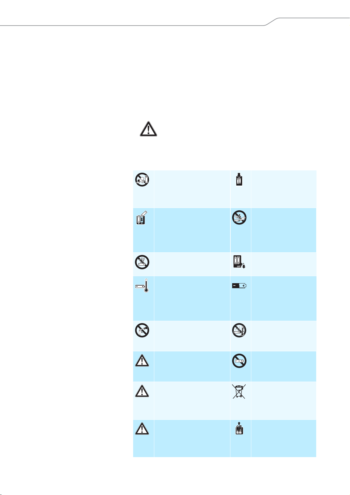
Safety instructions for lithium-ion rechargeable batteries
If abused or misused, the rechargeable batteries of the SK 9000/SKM 9000
may leak. In extreme cases, they may even present a risk of
•explosion,
• fire development,
• heat generation,
• smoke or gas development.
Sennheiser does not accept any liability for damage arising from abuse or
misuse.
Keep away from children. Only charge
rechargeable batteries
with a charger
recommended by
Sennheiser.
Observe correct polarity. Pack/store charged
rechargeable batteries
so that the terminals
cannot contact each
other – danger of
shorting out/fire hazard.
Do not expose to moisture. Switch rechargeable
battery-powered
products off after use.
Only charge rechargeable
batteries at ambient
temperatures between
10°C/50°F and 40°C/104°F.
Do not mutilate or dismantle. Do not heat above
Immediately remove
rechargeable batteries
from an obviously
defective product.
Only use rechargeable
batteries specified by
Sennheiser.
Store the product in
a cool and dry place at
room temperature
(approx. 20°C/68°F).
When not using
rechargeable batteries
for extended periods
of time, charge them
regularly (about every
three months).
70°C/158°F, e.g. do not
expose to sunlight or
throw into a fire.
Do not continue to use
defective rechargeable
batteries.
Dispose of rechargeable
batteries at special
collection points or
return them to your
specialist dealer.
Remove the
rechargeable batteries if
the product will not be
used for extended
periods of time.
1.6.12 | Digital 9000 | 7
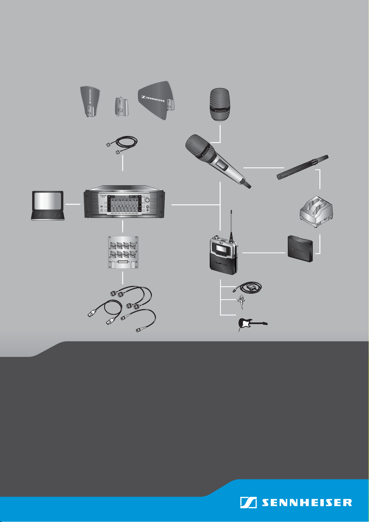
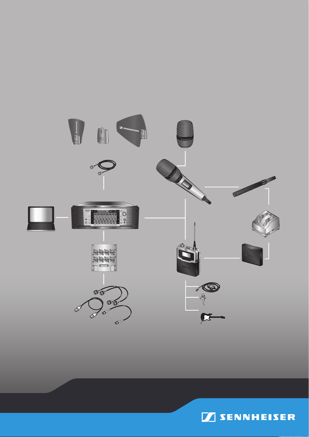
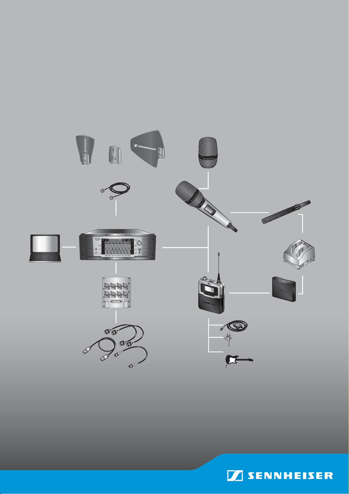
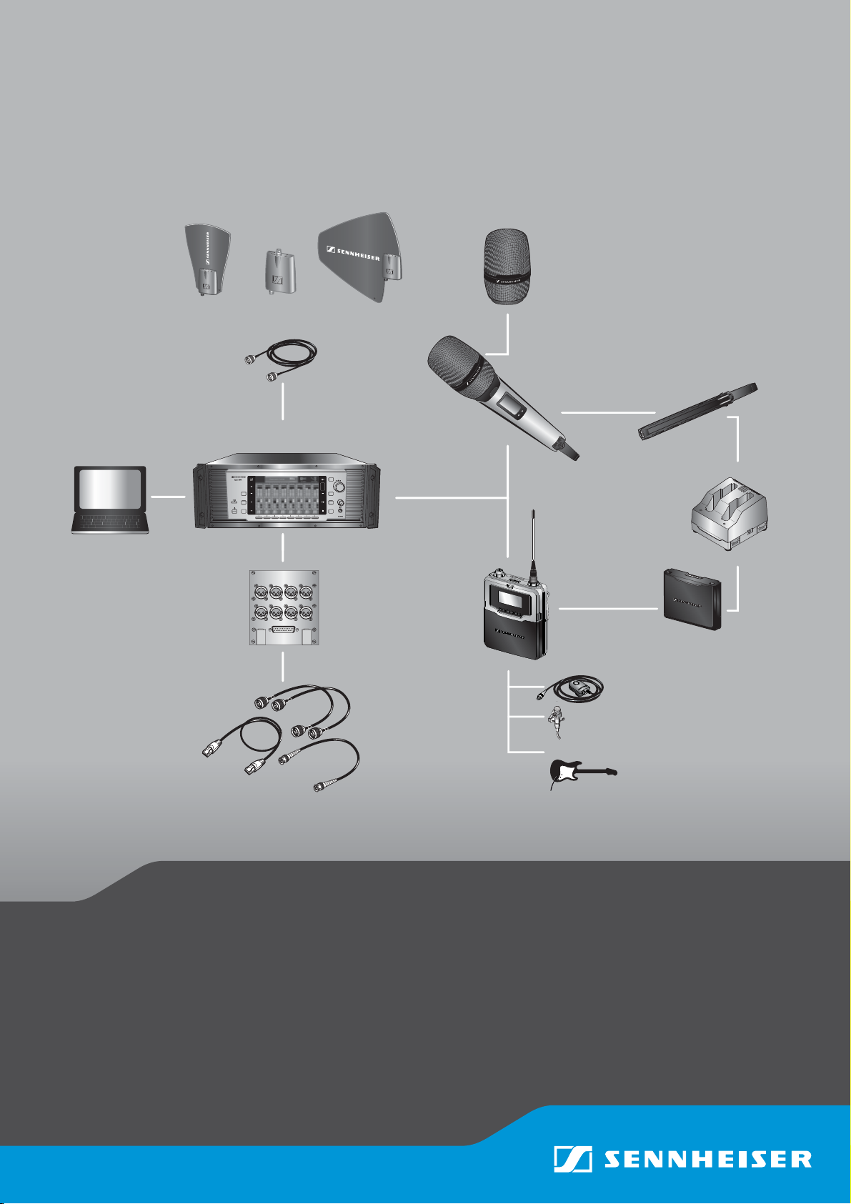
Digital 9000 – System overview
System overview
Digital 9000
B 60
BA 60
B 61
BA 61
L 60
MKE 1
MKE 2
...
EM 9046 DRX
EM 9046 AAO
EM 9046 DAO
EM 9046 CAB
EM 9046 CAB
KA 9000 COM
CI 1-4
GZL 9000-A5
GZL 9000-A10
GZL 9000-A20
AD 9000
EM 9046
SK 9000
SKM 9000
SKM 9000 COM
WSM
A 9000
AB 9000
ME 9002
ME 9004
ME 9005
...
Digital 9000 – System overview
Digital 9000 – System overview ............................................ 8
EM 9046 receiver ..................................................................9
Antennas and antenna boosters .......................................9
SKM 9000 radio microphone/
SK 9000 bodypack transmitter ........................................10
L 60 charger .........................................................................10
Delivery includes ....................................................................11
EM 9046 receiver ................................................................11
EM 9046 CAB cable set ......................................................11
Antennas and antenna boosters .....................................11
GZL 9000 antenna cables ..................................................11
SKM 9000/SKM 9000 COM radio microphone ...............12
Microphone heads for the SKM 9000 radio
microphone ..........................................................................12
SK 9000 bodypack transmitter ........................................12
Microphones for the SK 9000 bodypack
transmitter ...........................................................................12
KA 9000 COM command adapter for the
SK 9000 bodypack transmitter ........................................12
CI 1-4 line/instrument cable for the
SK 9000 bodypack transmitter ....................................... 12
B 60/B 61 battery packs ................................................... 13
BA 60/BA 61 accupack ...................................................... 13
L 60 charger ........................................................................ 13
Product overview ................................................................... 14
EM 9046 receiver ................................................................ 14
Antennas and antenna boosters A/AB/AD 9000 ........ 18
GZL 9000 antenna cable ................................................... 19
SKM 9000/SKM 9000 COM radio microphone .............. 19
SK 9000 bodypack transmitter ....................................... 21
KA 9000 COM command adapter for the
SK 9000 bodypack transmitter ....................................... 22
BA 60 accupack ................................................................... 23
BA 61 accupack ................................................................... 23
B 60 battery pack ............................................................... 24
B 61 battery pack ............................................................... 24
L 60 charger ........................................................................ 25
8 | Digital 9000

Digital 9000 – System overview
The Digital 9000 system
The Digital 9000 system is characterized by its high transmission reliability and easy of use. The large switching bandwidth as well as various different connection possibilities offer great flexibility in daily use.
• Outstanding sound quality due to digital transmission technology
• Efficient use of the available frequency spectrum
• Frequencies tuneable in 25 kHz steps
• Switching bandwidth across the entire UHF range (470 MHz to 798 MHz)
• Encryption of the digital audio signal
• Intuitive, icon-based operating menu
• Modular system
• Infra-red synchronization of receivers and transmitters
• WSM-assisted
EM 9046 receiver
• Scan function
• True bit diversity technology
• Audio output level adjustable in 1 dB steps
• Configurable Command audio output
• EM 9046 receiver can be equipped with up to 8 EM 9046 DRX receiver
modules for 8 individually adjustable channels
• Optional audio modules: transformer balanced analog or digital (AES3)
• Up to 4 receivers can be RF daisy chained
• High quality antenna splitters with booster supply
• Internal and external word clock synchronization of digital audio
outputs
• Ethernet socket for connection to a PC and/or for connection of several
receivers in a network
• Headphone output with high gain reserve
Antennas and antenna boosters
• A 9000 active, intelligent, omni-directional antenna
• AD 9000 active, intelligent, directional antenna
• AB 9000 active, intelligent antenna booster
• Power supply via EM 9046
• EM 9046-controlled preselection of booster frequency ranges
“A1”...“A8” or “B1” ... “B8” (24 MHz respectively)
• Automatic calibration of cable attenuation
• Can also be used with other receivers with booster supply voltage
(e.g. EM 3732-II)
Digital 9000 | 9

Digital 9000 – System overview
SKM 9000 radio microphone/ SK 9000 bodypack transmitter
The SKM 9000 and SK 9000 transmitters offer great ease of use and can
easily be adapted to any transmission situation:
• Rugged housing
• Input gain adjustable in 3 dB steps
• Switchable 1 kHz test tone, useful for level matching the system and
for the walk test
• High accuracy of charge status display (B/BA 60/61) or remaining
operating time display (B 60/61)
• Detection and support of the type of microphone head being used, incl.
Neumann microphone heads
• Switchable low cut filter for filtering out low frequency components
• Frequencies tuneable in 25 kHz steps
SKM 9000 radio microphone
• Power supply optionally via BA 60 lithium-ion accupack or B 60 battery
pack (2 AA size alkaline batteries or 2 AA size lithium batteries)
• Different microphone heads for different areas of application
(see page 20)
• Optionally available with command function (SKM 9000 COM)
SK 9000 bodypack transmitter
• Power supply optionally via BA 61 lithium-ion accupack or B 61 battery
pack (3 AA size alkaline batteries or 3 AA size lithium batteries)
• Automatic detection of the input signal type (mic, line, instrument)
when Sennheiser accessories are used
• Emulation of different instrument cable lengths
• Different clip-on microphones for different areas of application
(see page 22)
• Command function via KA 9000 COM command adapter
L 60 charger
• Simultaneous charging of up to two BA 60/BA 61 accupacks
• Up to four chargers can be cascaded together
10 | Digital 9000

Delivery includes
Delivery includes
You can make up your own Digital 9000 system with the following
components:
EM 9046 receiver
1 EM 9046 receiver
fixedly equipped with
- PSU power supply unit
- CCC core clock controller
- ASP antenna splitter
-AUX blanking plate
optionally equipped with
- up to eight EM 9046 DRX receiver modules and
- AAO/DAO analog/digital audio out modules
3 mains cables (with EU, UK and US plug)
1CAT 5 Ethernet cable
1 instruction manual
1CD ROM with
- “Wireless Systems Manager” (WSM) software
- WSM instruction manual
1 CD ROM with instruction manual for the Digital 9000 system
The optional EM 9046 DRX, AAO and DAO modules can be purchased
from and must be assembled by your Sennheiser service partner.
EM 9046 CAB cable set
2 RF patch cable (type N, 50 )
1 Ethernet patch cable (RJ45 connectors, CAT 5)
1 Word clock patch cable (BNC, 75 )
Antennas and antenna boosters
1 A 9000 omni-directional antenna or
1 AD 9000 directional antenna or
1 AB 9000 antenna booster
1 supplement
GZL 9000 antenna cables
1 GZL 9000-A5 antenna cable (length 5 m) or
1 GZL 9000-A10 antenna cable (length 10 m) or
1 GZL 9000-A20 antenna cable (length 20 m)
Digital 9000 | 11

Delivery includes
SKM 9000/SKM 9000 COM radio microphone
1 SKM 9000 radio microphone or
1 SKM 9000 COM radio microphone
1 MZQ 9000 microphone clamp
1 supplement “Framework requirements and restrictions on frequency
usage in Europe”
1instruction manual
You additionally require microphone heads as well as a BA 60 accupack and/or a B 60 battery pack. If you are using the BA 60 accupack, you will also require an L 60 charger.
Microphone heads for the SKM 9000 radio microphone
1microphone head
1 MZQ 9000 microphone clamp
1instruction manual
For an overview of all microphone heads for the SKM 9000 radio
microphone, refer to page 20.
SK 9000 bodypack transmitter
1 SK 9000 bodypack transmitter
1 supplement “Framework requirements and restrictions on frequency
usage in Europe”
1instruction manual
You additionally require microphones or the CI 1-4 line/instrument
cable as well as a BA 61 accupack and/or a B 61 battery pack. If you
are using the BA 61 accupack, you will also require an L 60 charger
Microphones for the SK 9000 bodypack transmitter
1microphone
1instruction manual
For an overview of all microphones for the SK 9000 bodypack transmitter, refer to page 22.
KA 9000 COM command adapter for the SK 9000 bodypack transmitter
1command adapter
1instruction manual
12 | Digital 9000
CI 1-4 line/instrument cable for the SK 9000 bodypack transmitter
1 CI 1-4 line/instrument cable
1instruction manual

Delivery includes
A list of accessories can be found on the Digital 9000 product page
at www.sennheiser.com. For information on suppliers, contact your
local Sennheiser partner: www.sennheiser.com >“Service & Support“.
B 60/B 61 battery packs
1 B 60 battery pack for SKM 9000 radio microphone or
1 B 61 battery pack for SK 9000 bodypack transmitter
1instruction manual
BA 60/BA 61 accupack
1 BA 60 accupack for SKM 9000 radio microphone or
1 BA 61 accupack for SK 9000 bodypack transmitter
1instruction manual
L 60 charger
1 L 60 charger for BA 60/BA 61 accupacks
1instruction manual
For powering the L 60 charger, you require the NT 3-1 mains unit
with a country-specific mains cable (EU, UK or US version).
One NT 3-1 mains unit can power up to four chargers.
Digital 9000 | 13
Product overview
1 12 23 5 7 8 9 A B C D G64 0
H
I
L KM J
FE
PON
Product overview
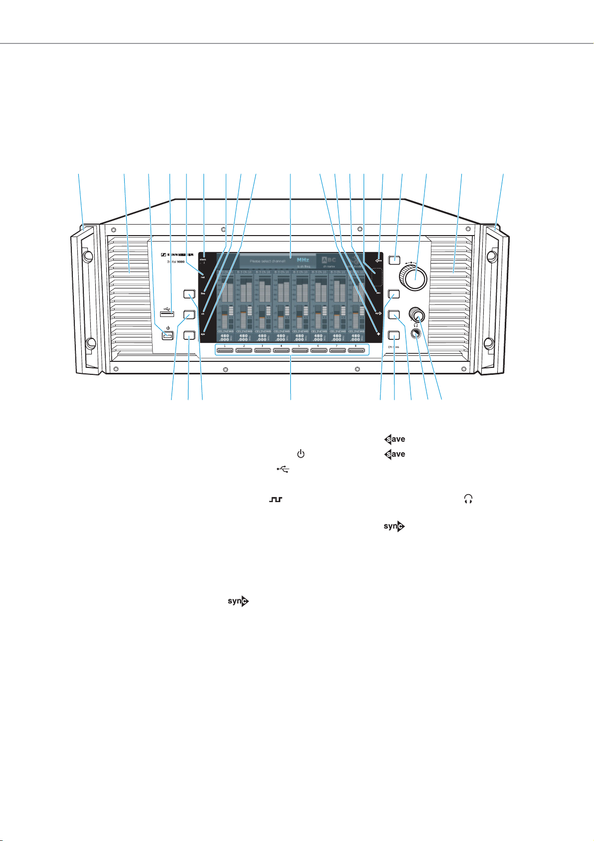
EM 9046 receiver
Overview of the front panel
1 Rack-mount “ear” with handle
2 Ventilation openings
3 Standby button
4 USB socket
5 net LED (network)
6 clock LED (external word
7 live LED
8 ch LED
9 sys LED
0 Display panel
A + LED
B LED
C esc LED
clock synchronization)
D Infra-red interface
E LED
F button
G Jog dial for menu control
H Headphone volume control
I Headphone socket ,
¼” (6.3 mm) jack socket
J button
K Multiple channel selection
button +
L esc button
M Channel 1 to 8 button
N live button
(for selecting the “live”
operating mode)
O sys button
(for configuring the system)
P ch button
(for configuring the channels)
14 | Digital 9000
Product overview
HDEDE
AB DCEF
G
H
I
I
4
G
H
3
1
2
A
0
C
5
E
F
9
B
D
I
J
8
7
6
K
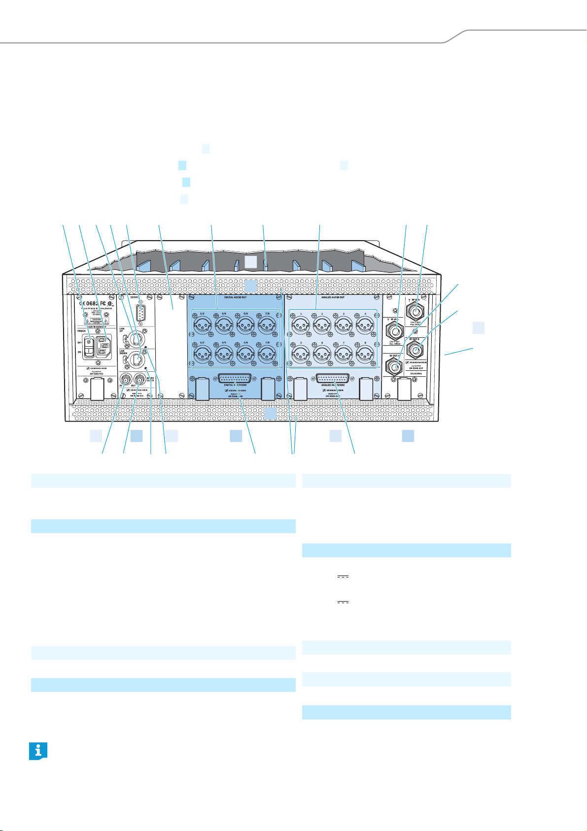
A | PSU – power supply unit
B | CCC – clock core controller
C | Aux opening for optional extensions
D | DAO – digital audio out
E | AAO – analog audio out
F | ASP – antenna splitter
G | Type plate
H | DRX – receiver modules
I | Ventilation openings
Overview of the rear panel
The overview of the rear panel shows an EM 9046 receiver equipped with the fixed PSU, CCC and ASP modules and the
optional DRX, DAO and AAO modules. The configuration shown is an example configuration. The interchangeable modules are highlighted in color.
Your Sennheiser service partner can configure the EM 9046 as follows:
• 1 to 8 EM 9046 DRX receiver modules
•1 AAO analog audio out module and 1 DAO digital audio out module or
•2 AAO analog audio out modules or
•2 DAO digital audio out modules
1 ON/OFF switch
2 IEC mains socket, 3-pin
3 LAN UP socket
4 LAN DOWN socket
5 SERVICE interface
6 LAN UP LED
7 LAN DOWN LED
8 WORD CLOCK OUT socket (BNC),
9 WORD CLOCK IN socket (BNC), input (75 )
0 Blanking plate for aux opening
A XLR-3 sockets (male) for digital audio outputs
B DIGITAL MUTLICORE socket (sub-D, 25-pin), digital, balanced
looped-through output (75 )
1/2 to 7/8, balanced, AES3
For the pin assignment of the XLR-3 and sub-D sockets of the EM 9046, refer to the chapter “Specifications”
on page 106.
C XLR-3 sockets (male) for analog audio outputs
1 to 8, transformer balanced
D ANALOG MULTICORE socket (sub-D, 25-pin),
analog, transformer balanced
E RF IN A socket (N-type), antenna input,
12 V out, max. 200 mA, 50
F RF IN B socket (N-type), antenna input,
G RF OUT A socket (N-type), daisy chain output
H RF OUT B socket (N-type), daisy chain output
12 V out, max. 200 mA, 50
I EM 9046 type plate
J DRX receiver modules 1 ... 8
K Ventilation openings
Digital 9000 | 15
Product overview
473
800
fs
473
800
473
800
473
800
fs
3:10
4
A A
HD
1
3:10
2
3
4
6
7
8
9
0
5
A1.7 A1.7 A1.7
CH3
A1.7
CH3
CH3 CH3
A1.7
range
low bat.
no signal
peak
booster
sync fail
encryption
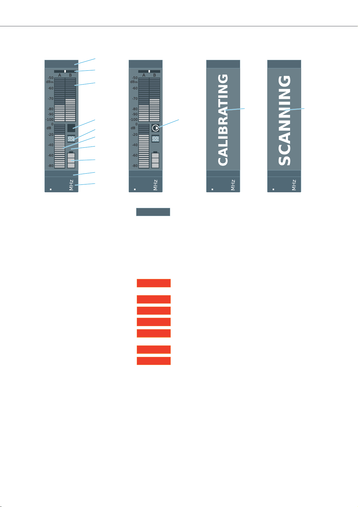
Overview of the displays and the clock LED
1 Frequency preset display
A Selected booster (type A or type B)
1 Selected booster frequency range (1 ... 8)
(bandwidth: 24 MHz)
7 Frequency preset (1 ... 40)
In addition, channel-related warnings are displayed in alternation with
the frequency preset display:
The frequency range set is outside the booster
frequency range
Charge status of accupack/battery pack is critical
No evaluable RF signal
Audio signal is overmodulated
No booster connected to one or both RF IN A/B
N-type sockets
Infra-red synchronization has failed
Audio signal of this channel is bound to the
EM 9046
2 Diversity evaluation display (true bit diversity)
3 Antenna signal display (dBm)
4 “HD”/“LR” and “Command” display
5 “Encryption” display
6 Audio level display (dBfs)
7 Display for remaining operating time of the transmitter
8 Display for charge status of accupack/battery pack
9 Channel name display
0 Receiving channel display
A Channel status displays (examples)
16 | Digital 9000

Product overview
The clock LED
The clock LED 6 provides information on the following states:
clock LED Meaning
lights up The receiver’s digital audio output is synchronized
with an external word clock signal.
flashes The “Word clock” menu item is set to “external”, but
the EM 9046 receiver cannot find an external word
clock signal and generates its own word clock signal.
The word clock rate of this signal corresponds to the
last set or active word clock rate. As soon as an external word clock signal is present at the WORD CLOCK IN
BNC socket 9, the digital audio output of the
EM 9046 automatically synchronizes with it and the
clock LED 6 lights up constantly.
if off The EM 9046 receiver generates its own word clock
signal.
Digital 9000 | 17
Product overview
RF out
Filter
on
Com
1
4
1
3
4
5
4
94
2
A 9000
AB 9000
AD 9000
2
3
5
2
6
5
7
8
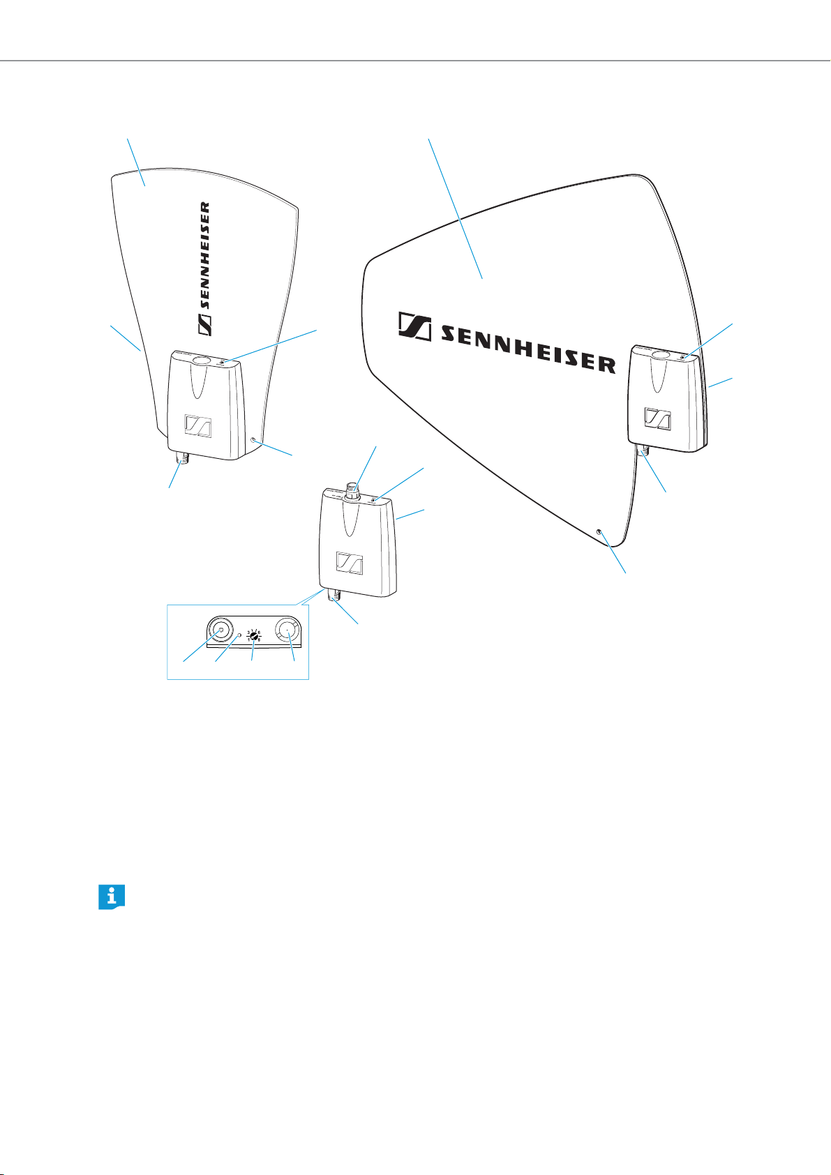
Antennas and antenna boosters A/AB/AD9000
1 Antenna surface
2 and 9: “Com” and “On” LED
- red: error
- green: manual mode
- blue: automatic mode (EM 9046-controlled)
- white: firmware update in progress
3 Hole for connection of safety wires
4 RF out socket (N-type)
If you are using the antennas/antenna booster with the EM 9046, the “Filter” rotary switch has no function because the frequency range is automatically set. If you are not using the antennas/antenna booster
with the EM 9046, the “Filter” rotary switch allows you to set the desired frequency range (“A1” ... “A8”
or “B1” ... “B8”).
5 Type plate (not visible here)
6 RF in socket (N-type)
(AB 9000 only)
7 Stand adapter
8 “Filter” rotary switch (see below)
18 | Digital 9000
Product overview
2
1 2
6
7
8
A
C
0
9
B
D
D
4
5
3
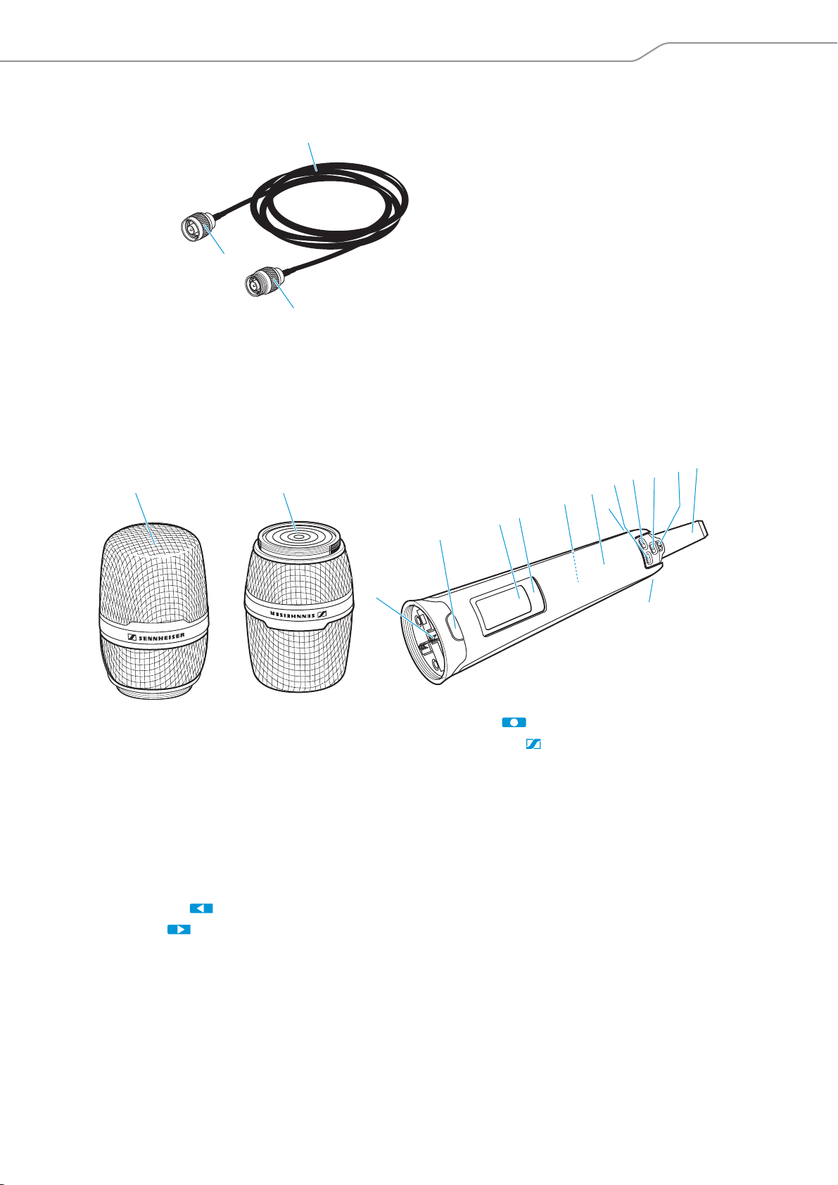
GZL 9000 antenna cable
3
1
1 GZL cable, available in lengths of 5 m,
10 m and 20 m
2 N-type connector
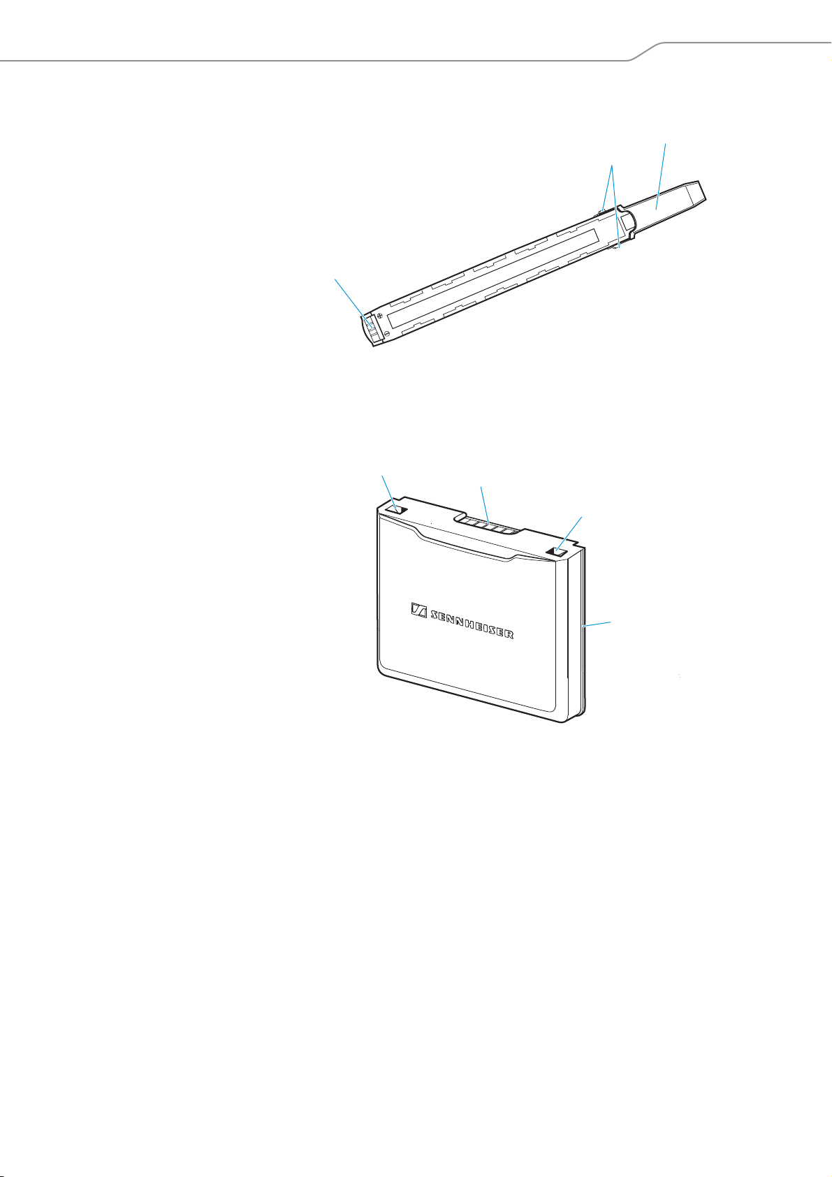
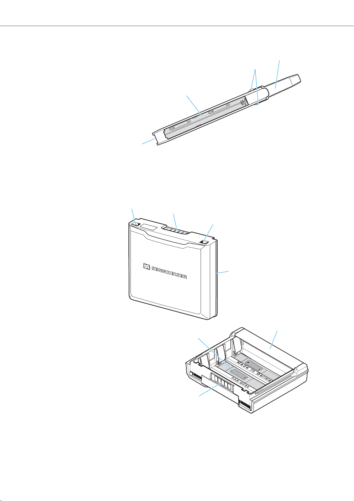
SKM 9000/SKM 9000 COM radio microphone
1 Microphone head
2 Contacts of microphone head
3 Contacts of radio microphone
4 COMMAND button
(SKM 9000 COM)
5 Display panel
6 Infra-red interface
7 Accupack or battery pack for 2 AA size cells
8 Body of radio microphone
9 DOWN button
0 UP button
3 N-type socket
A SET button
B ON/OFF button
with ESC function (cancel)
- lights up constantly:
radio microphone is operational
C Antenna
D Catches
for accupack/battery pack
Digital 9000 | 19
Product overview
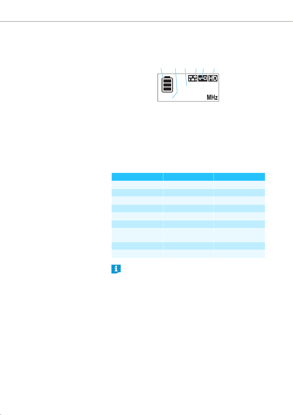
3:59
480.000
1 3 54 62
Overview of the standard display after switch-on
After switch-on, the radio microphone displays the currently selected standard display (here: “Frequency”). For an overview of all standard displays,
refer to page 80.
1 Display for charge status of the
accupack/battery pack
2 Operating time display (only
when used with the BA 60
accupack)
3 Frequency/channel/name
display, switchable
4 “Encryption” display
5 Lock mode icon
6 Transmission mode display:
“HD” (High Definition Audio) or
“LR” (Long Range Audio)
Recommended microphone heads for the SKM 9000
radio microphone
Microphone head Pick-up pattern Transducer principle
ME 9002 omni-directional condenser
ME 9004 cardioid condenser
ME 9005 super-cardioid condenser
MD 9235 super-cardioid dynamic
MMD 935-1 cardioid dynamic
MMD 945-1 super-cardioid dynamic
MMK 965-1 cardioid/super-
cardioid, switchable
KK 204 (Neumann) cardioid condenser
KK 205 (Neumann) super-cardioid condenser
permanently polarized
You can also use your radio microphone together with the microphone heads of the ew G3 and 2000 series.
20 | Digital 9000
Product overview
1
3
2
4
6
5
7
8
9
A
D
E
F
9
C
B
0
0
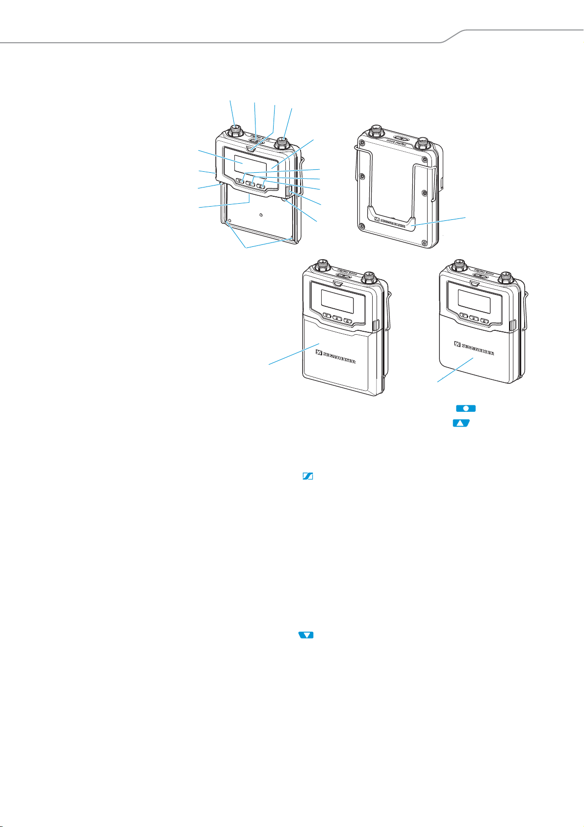
SK 9000 bodypack transmitter
1 3-pin special audio socket
for
- Sennheiser microphones
- CI 1-4 Sennheiser instrument cable
- KA 9000 COM command adapter
2 ON/OFF button
with ESC function (cancel)
3 ON LED
- lights up constantly:
transmitter is operational
- flashes regularly:
remaining operating time is less
than 30 minutes
- flashes with high levels:
audio signal is excessively high
4 Antenna socket
5 Infra-red interface
6 DOWN button
7 SET button
8 UP button
9 Catches
for accupack/battery pack
0 Snap-in elements
for accupack/battery pack
A Guide rails
for accupack/battery pack
B Contacts
for supply voltage and
data contacts
C Display panel
D Belt clip
E Battery pack
for 3 AA size cells
F Accupack
Digital 9000 | 21

Product overview
3:59
480.000
1 3 54 62
2
3
4
1
Overview of the standard display after switch-on
After switch-on, the bodypack transmitter displays the currently selected
standard display (here: “Frequency”). For an overview of all standard dis-
plays, refer to page 86.
1 Display for charge status of the
accupack/battery pack
2 Operating time display (only
when used with the BA 61)
3 Frequency/channel/name
display, switchable
4 “Encryption” display
5 Lock mode icon
6 Transmission mode display:
“HD” (High Definition Audio) or
“LR” (Long Range Audio)
Microphones for the SK 9000 bodypack transmitter
Microphone Pick-up pattern
MKE 1 omni-directional
MKE 2 cardioid
ME 102 omni-directional
ME 104 cardioid
ME 105 super-cardioid
HSP 2 omni-directional
HSP 4 cardioid
Sennheiser CI 1-4 line/instrument cable
¼’’ (6.3 mm) jack plug (silent plug) to 3-pin special audio connector
22 | Digital 9000
KA 9000 COM command adapter for the SK 9000 bodypack transmitter
1 3-pin special audio connector
2 COMMAND button
3 3-pin special audio socket
4 Connection cable, length: 1.6 m
Product overview
BA 60 accupack
3
2
1
1 Charging and data contacts
2 Snap-in elements
BA 61 accupack
1
1 Snap-in elements
2 Charging and data contacts
3 Antenna
2
1
3
3 Guide rail
Digital 9000 | 23
Product overview
4
B 60 battery pack
3
2
1
1 Battery compartment for
2 AA size batteries
2 Snap-in elements
B 61 battery pack
1
2
3 Antenna
4 Data contacts
1
3
5
4
24 | Digital 9000
1 Snap-in elements
2 Data contacts
2
3 Guide rail
4 Battery compartment for
3 AA size batteries
5 Cover
Product overview
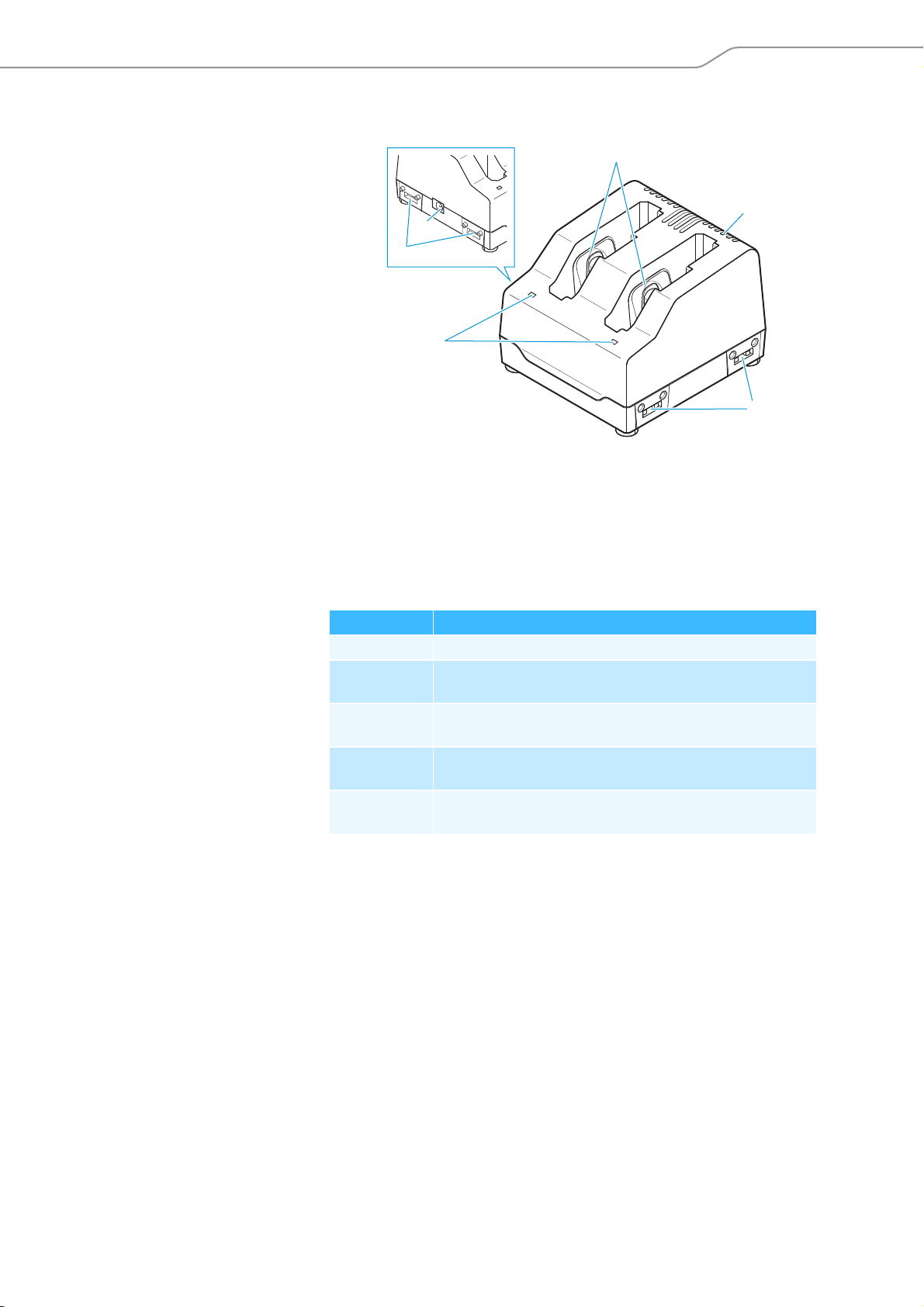
L 60 charger
3
4
2
5
1
5
1 Status LED
2 DC input socket for connection of
NT 3-1 mains unit
3 Charging compartments for
BA 60 or BA 61 accupacks
4 Ventilation openings
5 Rails for cascading up to
4chargers
Indications of the status LED
Status LED 1 Meaning
off Standby mode/no connection to the mains
red Accupack is being charged,
capacity obtained is approx. 0-70%
orange Accupack is being charged,
capacity obtained is approx. 70-100%
green Accupack is fully charged,
capacity is continuously monitored
flashing red Error, charging is aborted
(accupack is e.g. defective or overheated)
Digital 9000 | 25
ME 9002
ME 9004
ME 9005
...
B 60
BA 60
B 61
BA 61
L 60
MKE 1
MKE 2
...
EM 9046 DRX
EM 9046 AAO
EM 9046 DAO
EM 9046 CAB
EM 9046 CAB
KA 9000 COM
CI 1-4
GZL 9000-A5
GZL 9000-A10
GZL 9000-A20
AD 9000
EM 9046
SK 9000
WSM
A 9000
AB 9000
SKM 9000
SKM 9000 COM
Preparing for use
Digital 9000
Preparing the
Digital 9000 system for use
Preparing the EM 9046 receiver for use ............................. 27
Setting up the receiver or mounting it into a 19” rack ......27
Connecting devices to the analog audio outputs ................28
Connecting devices to the digital audio outputs .................29
Daisy chaining receivers ...........................................................29
Connecting external word clock signals ................................31
Connecting receivers in a network .........................................31
Connecting the receiver to the mains ....................................32
Connecting headphones ...........................................................33
Preparing the A/AB/AD 9000 antennas and/
or antenna boosters for use ......................................... 34
Positioning the receiving antennas .......................................34
Connecting the receiving antennas/antenna boosters ......35
Adjusting the receiving antennas/antenna boosters ........35
Preparing the SKM 9000 radio
microphone for use .........................................................35
Changing the microphone head ............................................. 37
Preparing the SK 9000 bodypack
transmitter for use .........................................................37
Connecting the antenna .......................................................... 40
Connecting the KA 9000 COM command adapter .............. 40
Preparing the L 60 charger for use ...............................41
Cascading several chargers ...........................................41
Setting up or mounting the charger ............................41
Preparing the Digital 9000 system for use
Preparing the EM 9046 receiver for use
Setting up the receiver or mounting it into a 19” rack
Setting up the receiver on a flat surface
CAUTION!
Risk of staining of furniture surfaces!
Furniture surfaces can be treated with varnish, polish or synthetics which
might cause stains when they come into contact with other synthetics.
Despite a thorough testing of the synthetics used by us, we cannot rule out
the possibility of staining.
왘 Do not place the receiver on delicate surfaces.
The receiver is supplied with 4 self-adhesive soft rubber feet to ensure that
it cannot slip on the surface on which it is placed.
Do not fit the device feet when rack mounting the receiver.
왘 Ensure that the base of the receiver is clean and free from grease before
fitting the device feet.
왘 Fit the device feet.
왘 Place the receiver on a flat, horizontal surface.
Mounting the receiver into a 19” rack
CAUTION
Danger of material damage and personal injury when rack
mounting the receiver!
When installing the EM 9046 in a closed or multi-rack assembly,
please consider that
• the ambient temperature may increase considerably,
• high mechanical loadings occur.
왘 Always make sure that the ambient temperature within the
rack does not exceed the permissible temperature limit specified in the specifications. If necessary, provide additional
ventilation.
왘 Do not obstruct the air flow through the ventilation openings
on the front and rear of the EM 9046.
왘 Always mount the receiver on rack rails.
왘 Make sure that the mechanical loading of the rack is even to
avoid, for example, tipping of the rack.
왘 Make sure that the rack is sufficiently stable.
왘 Avoid circuit overloading. If necessary, provide overcurrent
protection.
왘 Make sure that the mains cable of the EM 9046 as well as con-
nected multi-outlet power strips or extension cables have protective ground contacts.
왘 Always ground the rack via an additional ground connection.
Digital 9000 | 27
Preparing the Digital 9000 system for use
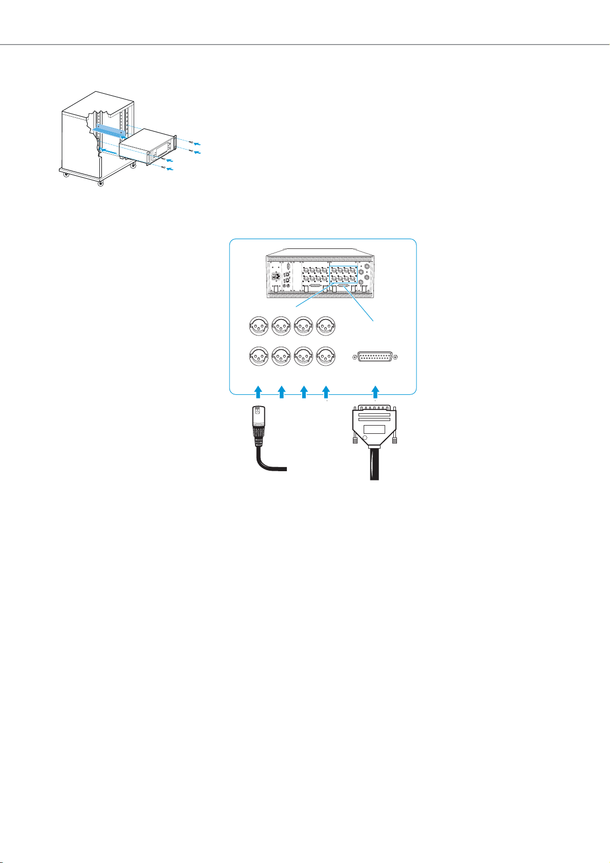
To mount the receiver into a 19” rack:
왘 Mount rack rails that are designed to carry the total weight of the
EM 9046.
Slide the receiver onto the rack rails and screw it to the front of the rack
using 2 screws per side (screws to be ordered separately).
Connecting devices to the analog audio outputs
When equipped with an AAO analog audio out module, the EM 9046
receiver has 8 analog transformer balanced audio outputs.
왘 Connect the analog audio inputs of an external device to the XLR-3
sockets C or the sub-D socket D (multicore, Tascam) of the EM 9046.
EM9046
AB DCEF
C
D
XLR XLR XLR XLR ANALOG MULTICORE
28 | Digital 9000
Preparing the Digital 9000 system for use
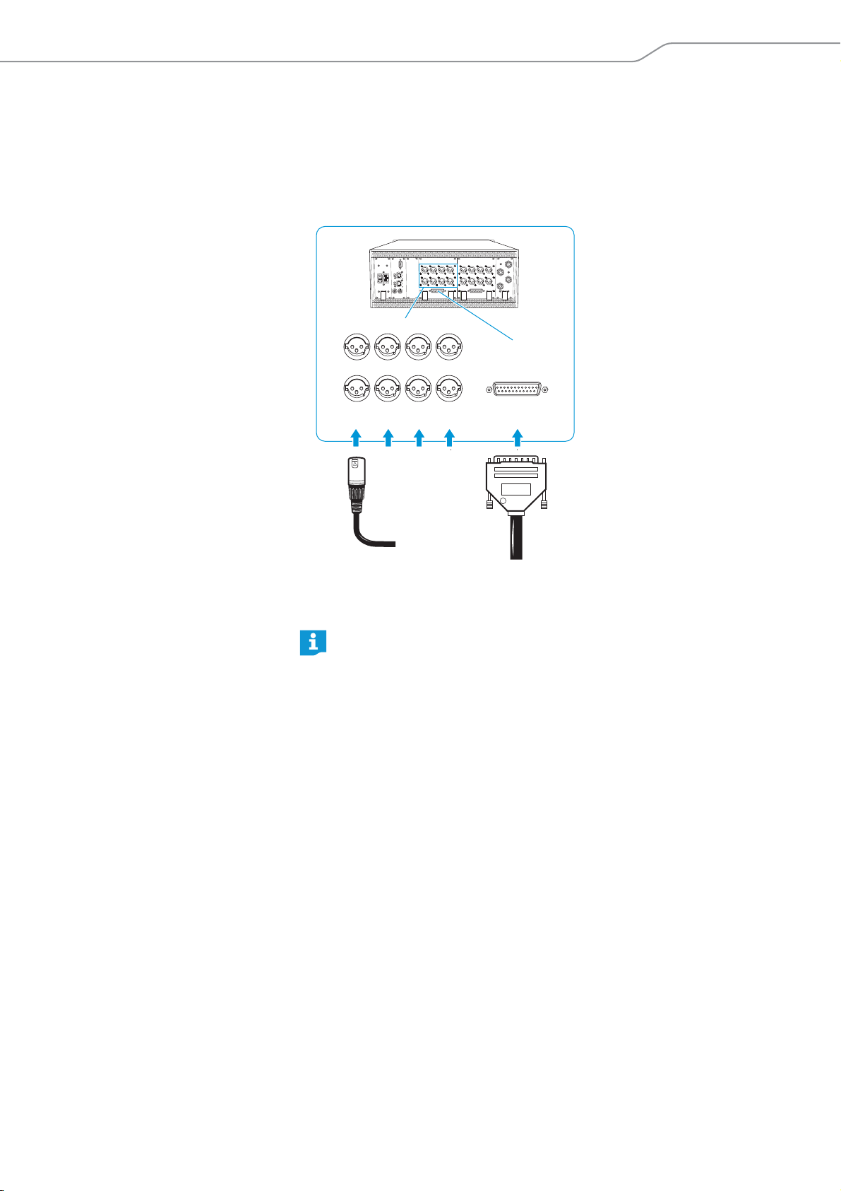
Connecting devices to the digital audio outputs
When equipped with an DAO digital audio out module, the EM 9046
receiver has 8 digital balanced audio outputs. The signals are output in
AES3 format.
왘 Connect the digital audio inputs of an external device to the XLR-3
sockets A or the sub-D socket B of the EM 9046.
EM9046
ABDCEF
A
B
XLR XLR XLR XLR DIGITAL MULTICORE
If you are using the XLR-3 sockets A:
왘 Use a special double-shielded 110 AES3 cable. This prevents that the
digital data transmission interferes with RF reception.
For the pin assignment of the XLR-3 and sub-D sockets of the
EM 9046, refer to the chapter “Specifications” on page 106.
Ready-made AES3 cables are available from Sennheiser (optional
accessories).
Daisy chaining receivers
The EM 9046 receivers feature an integrated antenna splitter so that up to
four receivers can be daisy chained. This allows you to use two antennas/
antenna boosters for up to four receivers. In this case, all receivers have to
use the same booster frequency range.
왘 Use GZL 9000 antenna cables to connect two antennas via antenna
boosters to the RF IN N-type sockets E and F of the first receiver.
Digital 9000 | 29
 Loading...