

Sennheiser SKM 500 G3 - 02-09, SKM 500 Instruction Manual

SKM 500
Instruction manual

1
Contents
Contents
Important safety instructions ............................................... 2
The SKM 500 G3 radio microphone family ......................... 3
The frequency bank system ............................................. 3
Areas of application ............................................................ 4
Delivery includes ....................................................................... 5
Product overview ...................................................................... 6
Overview of the SKM 500 G3 radio microphone ........... 6
Overview of the displays ................................................... 7
Putting the radio microphone into operation .................... 8
Inserting the batteries/accupack ..................................... 8
Charging the accupack ....................................................... 9
Changing the microphone head ....................................... 9
Changing the color-coded protection ring .................. 11
Using the radio microphone ................................................ 12
Switching the radio microphone on/off ..................... 12
Deactivating the lock mode temporarily ..................... 14
Deactivating the RF signal .............................................. 14
Selecting a standard display ......................................... 15
Using the operating menu ................................................... 16
The buttons ...................................................................... 16
Overview of the operating menu ................................. 17
Working with the operating menu .............................. 18
Adjusting settings via the operating menu .................... 20
The main menu “Menu” .................................................. 20
The extended menu “Advanced Menu” ....................... 22
Synchronizing the radio microphone with a receiver ... 26
Synchronizing the radio microphone
with the receiver – individual operation ..................... 26
Synchronizing radio microphones
with receivers – multi-channel operation ................... 26
Cleaning the radio microphone .......................................... 27
Recommendations and tips ............................................... 28
If a problem occurs ... ........................................................... 29
Accessories and spare parts ................................................ 30
Specifications .......................................................................... 31
Polar diagrams and frequency response curves
of the microphone heads ................................................ 32
Manufacturer Declarations .................................................. 34
Index ......................................................................................... 36
An animated instruction manual can be viewed
on the SKM 500 G3 product page on our
website at www.sennheiser.com.

2
Important safety instructions
Important safety instructions
• Read this instruction manual.
• Keep this instruction manual. Always include this
instruction manual when passing the product on to third
parties.
• Heed all warnings and follow all instructions in this
instruction manual.
• Use only a cloth for cleaning the product.
• Do not place the product near any heat sources such as
radiators, stoves, or other devices (including amplifiers)
that produce heat.
• Only use attachments/accessories specified by
Sennheiser.
• Refer all servicing to qualified service personnel.
Servicing is required if the product has been damaged in
any way, liquid has been spilled, objects have fallen
inside, the product has been exposed to rain or moisture, does not operate properly or has been dropped.
• WARNING: To reduce the risk of short circuits, do not use
the product near water and do not expose it to rain or
moisture.
Replacement parts
When replacement parts are required, be sure the service
technician uses replacement parts specified by Sennheiser
or those having the same characteristics as the original
part. Unauthorized substitutions may result in fire, electric
shock, or other hazards.
Intended use
Intended use of the ew 500 G3 series products includes:
• having read these instructions especially the chapter
“Important safety instructions”,
• using the products within the operating conditions and
limitations described in this instruction manual.
“Improper use” means using the products other than as
described in this instruction manual, or under operating
conditions which differ from those described herein.

3
The SKM 500 G3 radio microphone family
The SKM 500 G3
radio microphone family
This radio microphone is part of the evolution wireless
series generation 3 (ew G3). With this series, Sennheiser
offers high-quality state-of-the-art RF transmission
systems with a high level of operational reliability and ease
of use. Transmitters and receivers permit wireless transmission with studio-quality sound.
Features of the evolution wireless 500 G3 series:
• Optimized PLL synthesizer and microprocessor
technology
• HDX noise reduction system
• Pilot tone squelch control
• True diversity technology
• Switching bandwidth of 42 MHz
• Increased immunity to intermodulation and
interferences in multi-channel operation
• Interchangeable microphone heads, allowing the use of
different pick-up patterns and sensitivities
The frequency bank system
The radio microphone is available in 6 UHF frequency
ranges with 1,680 transmission frequencies per frequency
range:
Each frequency range (A–E, G) offers 26 frequency banks
with up to 32 channels each:
Each of the channels in the frequency banks “1” to “20” has
been factory-preset to a fixed frequency (frequency
preset).
The factory-preset frequencies within one frequency bank
are intermodulation-free. These frequencies cannot be
changed.
516 – 558
566 – 608
626 – 668
734 – 776
780 – 822
823 – 865
Range A: Range G: Range B: Range C: Range D: Range E:
Frequency bank 1... 20
Frequency bank U1 ... U6
Channel 32 – frequency preset
Channel 1 – frequency preset
Channel 2 – frequency preset
Channel 32 – freely selectable frequency
Channel 1 – freely selectable frequency
Channel 2 – freely selectable frequency
4
The SKM 500 G3 radio microphone family
For an overview of the frequency presets, please refer to the
supplied frequency information sheet. Updated versions of
the frequency information sheet can be downloaded from
the SKM 500 G3 product page on our website at
www.sennheiser.com.
The frequency banks “U1” to “U6” allow you to freely select
and store frequencies. It might be that these frequencies
are not intermodulation-free.
Areas of application
The radio microphone can be combined with the EM 500 G3
rack-mount receiver.
The EM 500 G3 rack-mount receiver is available in the same
UHF frequency ranges and is equipped with the same
frequency bank system with factory-preset frequencies.
This has the advantage that
• a transmission system is ready for immediate use after
switch-on,
• several transmission systems can be operated simultaneously on the preset frequencies without causing
intermodulation interference.
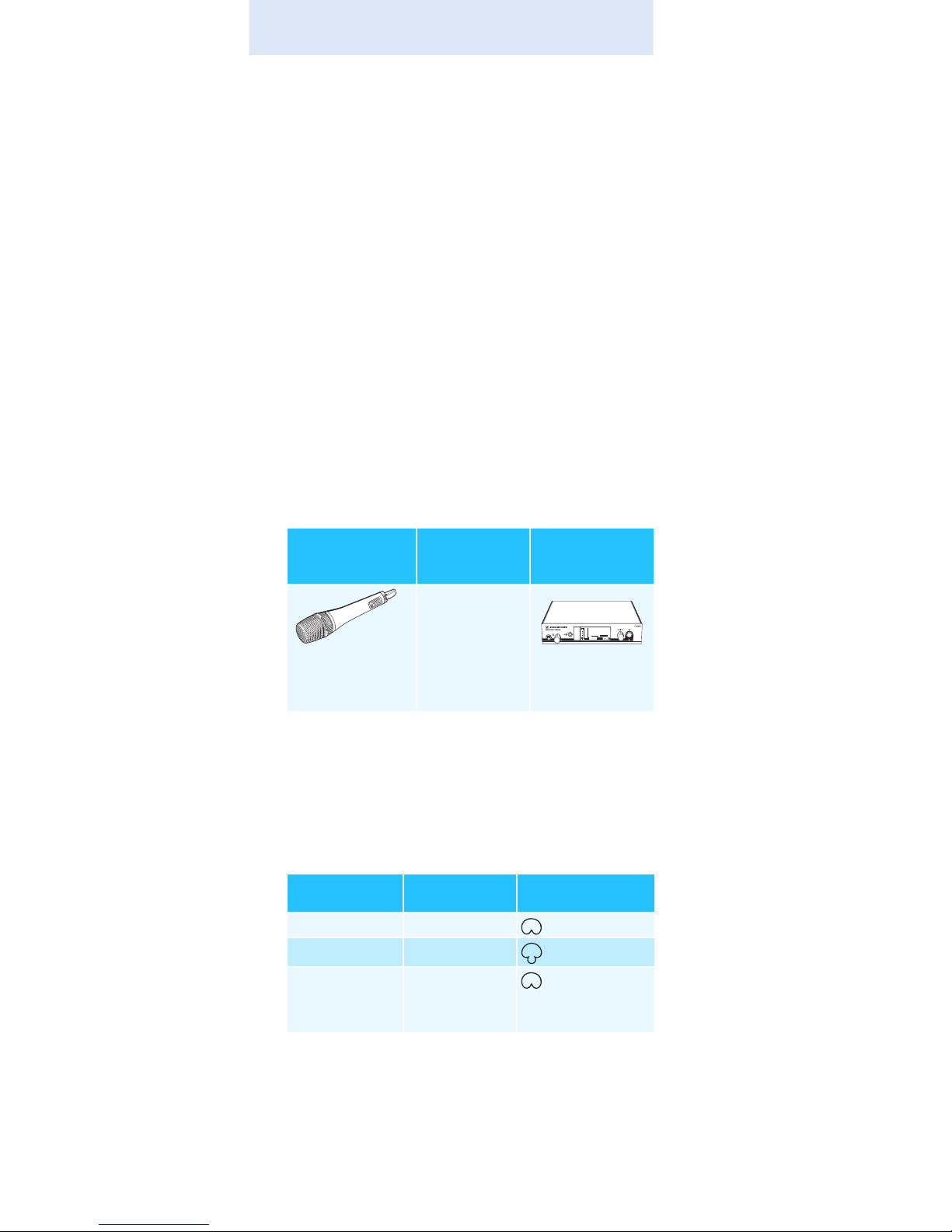
Overview of the microphone heads:
The name and pick-up pattern of the microphone head are
printed on the sound inlet basket of the radio microphone.
Radio microphone
Interchangeable microphone
heads
Receiver
SKM 500-935 G3*
SKM 500-945 G3
*
SKM 500-965 G3
*
* The name of the radio microphone is a combination of the
name of the transmitter and the name of the microphone
head:
Transmitter + microphone head = Name of radio
microphone
SKM 500 + MMD 935-1 = SKM 500-935
MMD 935-1
MMD 945-1
MMK 965-1
EM 500 G3
Microphone
head
Microphone
type
Pick-up pattern
MMD 935-1 dynamic
– cardioid
MMD 945-1 dynamic
– super-cardioid
MMK 965-1 condenser
– cardioid/
super-cardioid,
switchable
542.625
ew500 G3
B.Ch: 20.30
PEAK
MUTE
EQ
+ 12dB
-10
040
30
20
10
-20
-30
-40
AF
RF
MHz
SKM500
P

5
Delivery includes
Delivery includes
The packaging contains the following items:
1 SKM 500 G3 radio microphone incl. microphone head
2 AA size batteries, 1.5 V
1microphone clamp
1 instruction manual
1 frequency information sheet
1 RF licensing information sheet
1 HHP 2 pouch
6
Product overview
Product overview
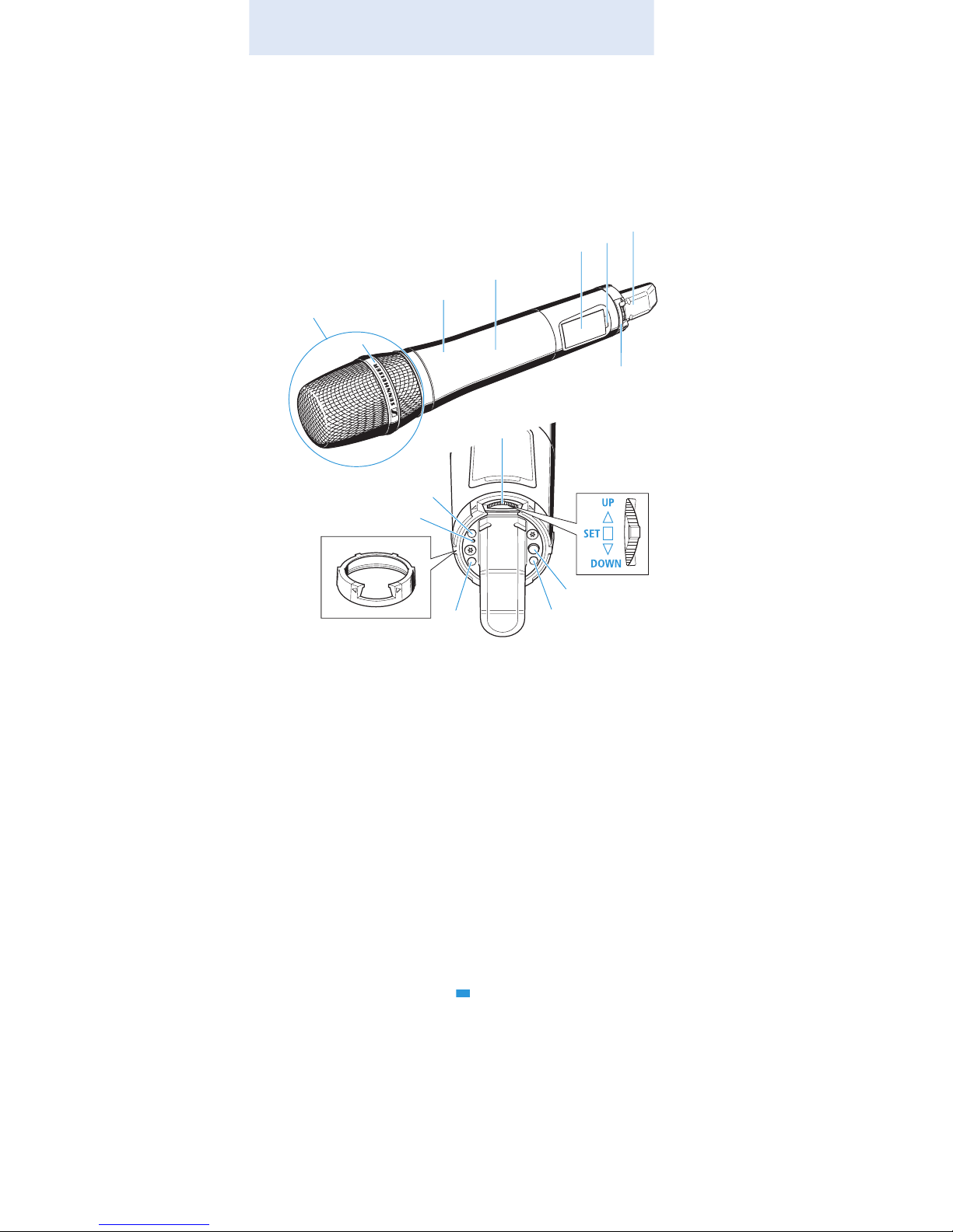
Overview of the SKM 500 G3 radio
microphone
쐃 Microphone head (interchangeable)
쐇 Name and pick-up pattern of the microphone head
(not visible here, see page 4)
쐋 Body of radio microphone
쐏 Battery compartment (not visible from outside)
쐄 Display panel, backlit in orange
쐂 Infra-red interface
쐆 Antenna
쐊 Color-coded protection ring;
available in different colors
쐎 Operation and battery status indicator, red LED
(lit = ON/flashing = LOW BATTERY)
쐅 Charging contacts
쐈 Multi-function switch:
(DOWN), (UP) and (SET)
쐉 ON/OFF button
with ESC function (cancel)
쐊
쐋
쐏
쐂
쐆
쐉
쐅
쐅
쐎
쐅
쐊
쐈
쐄
쐇
7
Product overview
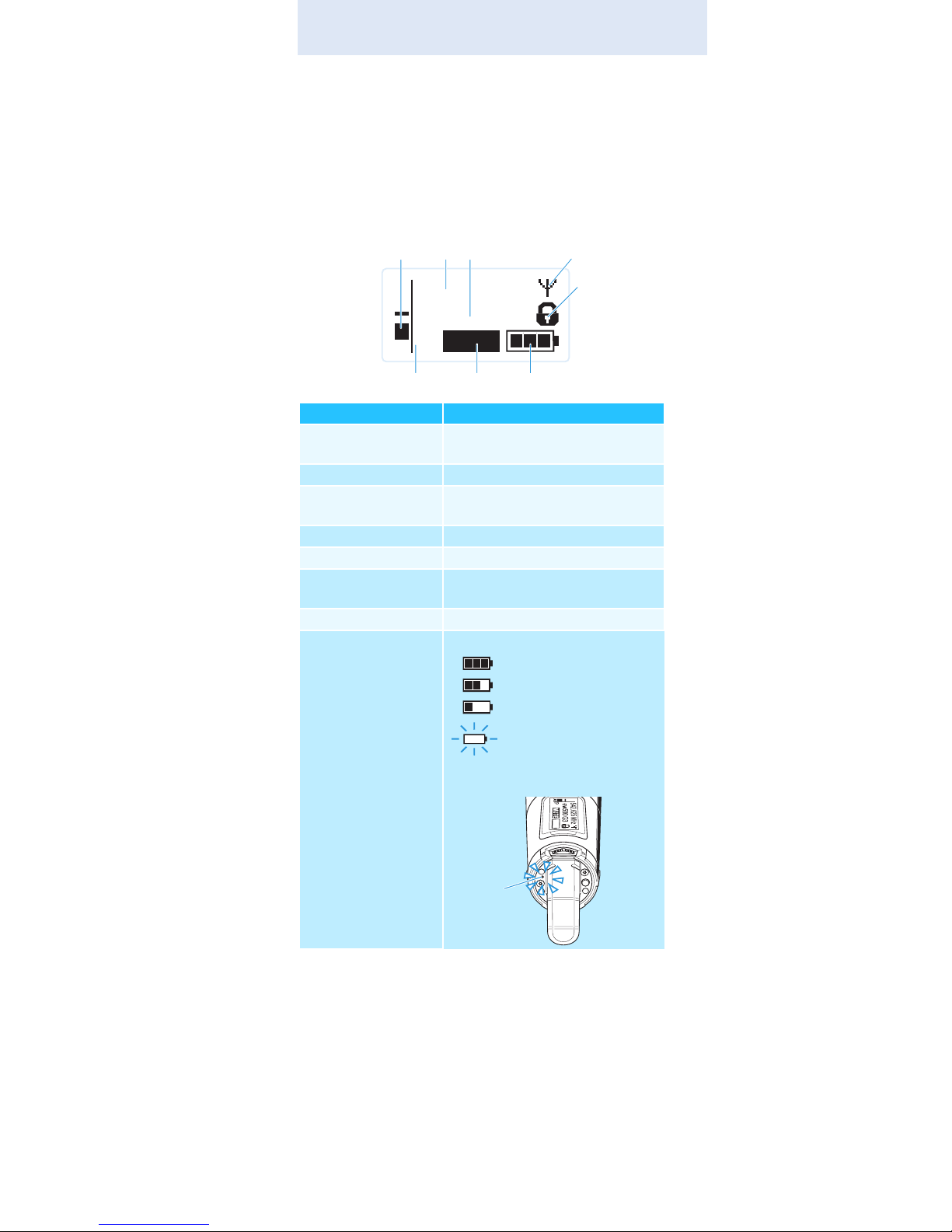
Overview of the displays
After switch-on, the radio microphone displays the
standard display “Frequency/Name”. For further illustrations and examples of the different standard displays, refer
to page 15.
The display backlighting is automatically reduced after
approx. 20 seconds.
Display Meaning
햲 Audio level “AF” Modulation of the radio micro-
phone with peak hold function
햳 Frequency Current transmission frequency
햴 Name Freely selectable name of the
transmitter
햵 Transmission icon RF signal is being transmitted
햶 Lock mode icon Lock mode is activated
햷 “P” (pilot tone) Pilot tone transmission is
activated
햸 “MUTE” Audio signal is muted
햹 Battery status Charge status:
approx. 100%
approx. 70%
approx. 30%
charge status is
critical
, the red
LOW BATTERY LED 쐎
is flashing:
MHz
542.625
ew500 G3
MUTE
P
AF
햳 햴햲
햶
햵
햹햸햷
쐎
8
Putting the radio microphone into operation
Putting the radio microphone
into operation
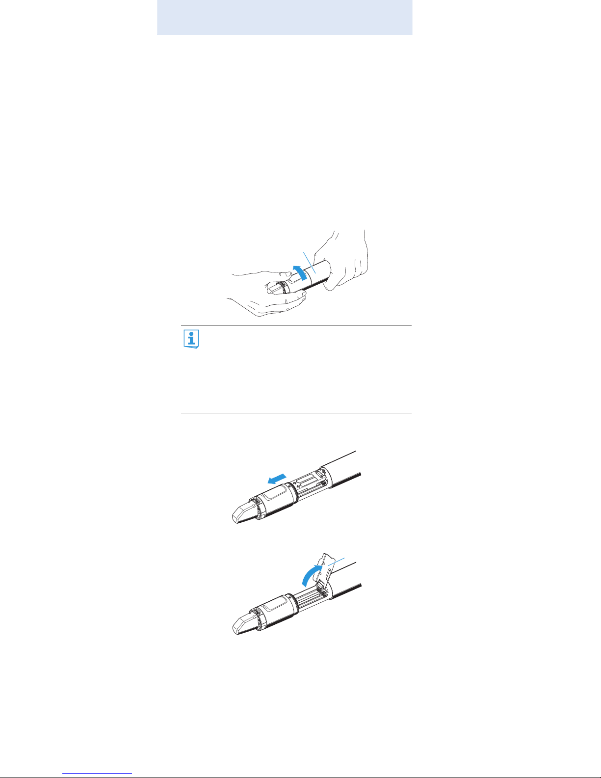
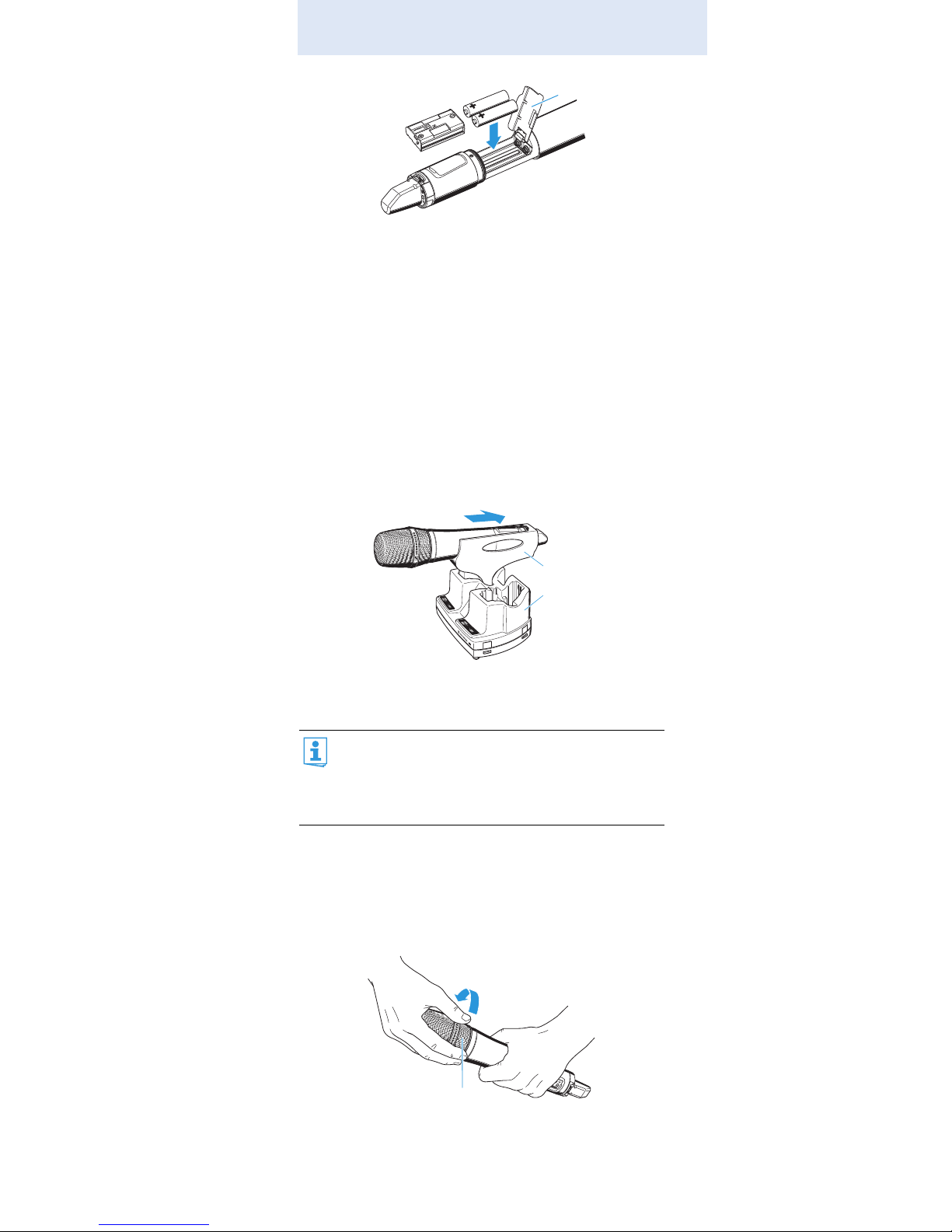
Inserting the batteries/accupack
For powering the radio microphone, you can either use two
1.5 V AA size batteries or the rechargeable Sennheiser
BA 2015 accupack (see “Accessories and spare parts” on
page 30).
Unscrew the lower part of the radio microphone from
the radio microphone’s body 쐋 by turning it counterclockwise.
Slide back the lower part of the radio microphone as far
as it will go.
Open the battery compartment cover 씈.
Insert the batteries or the BA 2015 accupack as shown
on the battery compartment cover. Observe correct
polarity when inserting the batteries/accupack.
When unscrewing the radio microphone during
operation, the muting function is automatically
activated. “MUTE” appears on the display panel.
When screwing the lower part of the radio microphone back to the radio microphone’s body, the
muting is canceled. “MUTE” disappears from the
display panel.
쐋
씈
9
Putting the radio microphone into operation
Close the battery compartment cover 씈.
Push the battery compartment into the radio micro-
phone’s body.
Screw the lower part of the radio microphone back to
the radio microphone’s body 쐋.
Charging the accupack
To charge the radio microphone with the BA 2015 accupack
(see “Accessories and spare parts” on page 30) installed:
Insert the radio microphone into the LA 2 charging
adapter (see “Accessories and spare parts” on page 30)
until it locks into place.
Plug the LA 2 charging adapter with the inserted radio
microphone into the L 2015 charger (see “Accessories
and spare parts” on page 30).
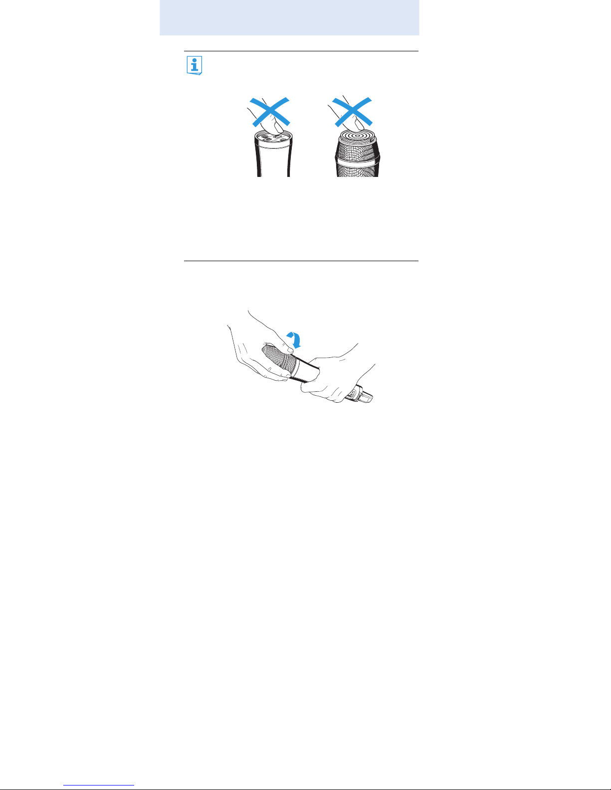
Changing the microphone head
The microphone head 쐃 is easy to change.
Unscrew the microphone head 쐃.
The LA 2 charging adapter and L 2015 charger can
only charge the radio microphone with the BA 2015
accupack installed. Standard batteries (primary
cells) or individual rechargeable battery cells cannot
be charged in this way.
씈
L 2015
LA 2
쐃
10
Putting the radio microphone into operation
Screw the desired microphone head to the radio micro-
phone.
The radio microphone is operational again.
Do not touch the contacts of the radio microphone
nor the contacts of the microphone head 쐃. The
contacts can become dirty or damaged if touched.
When unscrewing the microphone head 쐃 during
operation, the muting function is automatically activated. “MUTE” appears on the display panel.
When screwing the microphone head 쐃 back to the
radio microphone, the muting is canceled. “MUTE”
disappears from the display panel.
11
Putting the radio microphone into operation
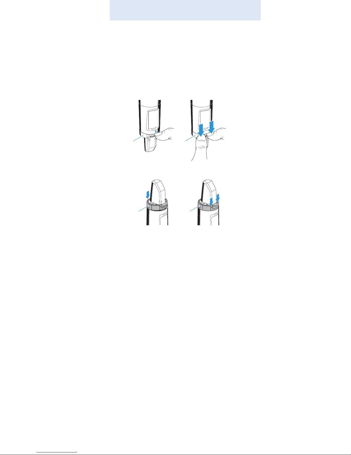
Changing the color-coded protection ring
The color-coded protection ring 쐊 prevents the multifunction switch from accidental operation.
Protection rings 쐊 in different colors are available as accessories (see “Accessories and spare parts” on page 30).
The protection rings allow you to clearly identify each radio
microphone.
Remove the color-coded protection ring 쐊 as shown.
Put on a new protection ring 쐊 as shown.
쐊 쐊
쐊 쐊
 Loading...