

Sennheiser SKM 500 G2, SKM 500 G2 - 02-06, SKM 535 G2, SKM 545 G2, SKM 565 G2 Instructions For Use Manual
...
EK 500
/
SKM 500
Instructions for use

2
Th ank you for ch oosin g S en nheiser!
We have designed this product to give you reliable
operation over many years. Over half a century of
accumulated expertise in the design and manufacture of
high-quality electro-acoustic equipment have made
Sennheiser a world-leading company in this field.
Please take a few moments to read these instructions
carefully, as we want you to enjoy your new Sennheiser
product quickly and to the fullest.

3
Contents
The SKM 500 G2 radiomicrophon e family ... ......... ............. ... 4
The channel bank system ...... ...... ...... ....... ...... ...... ....... ...... 4
Saf ety instructions ..... ...... ....... ...... ...... ...... ....... ...... ...... ....... ...... 5
Deli very inclu des ..... ...... ...... ....... ...... ...... ....... ...... ...... ...... ....... ... 5
Areas of application ......... ............. ............ .......... ... ......... .......... 6
The operating contr ols .... ... .......... ............ ............. ............. ...... 7
Indications and displays . ....... ...... ...... ...... ....... ...... ...... ....... ...... 8
Prepar ing the radiomi cropho ne for us e ............. ...... ....... ... 10
Inserting/replacin g the batteries .. ....... ...... ...... ...... ....... 10
Changin g th e microphone h ead ....... ....... ...... ...... ....... ... 11
Using the radio microp hone ... ...... ...... ...... ....... ...... ...... ....... ... 13
Switching the radiom icrophon e on/of f .... ...... ...... ....... 13
Muting the rad iomicr ophone ...... ...... ....... ...... ...... ....... ... 14
Activating/deactivating the lock mode . ...... ...... ....... ... 14
The operating menu ..... .......... ... ......... ... .......... ............ .......... 15
The buttons ..... ...... ...... ....... ...... ...... ...... ....... ...... ...... ....... ... 15
Overview of menus ....... ....... ...... ...... ....... ...... ...... ...... ....... 15
Working wi th the operating menu ............ ............ ....... 16
Operatin g menu of the rad iomicr ophone ....... ...... ....... 18
Adjustment tips for the operating menu . ......... ............. ... 20
Switching between c hannel banks ............ ...... ...... ....... 20
Switching between the channels in a c hannel bank . 20
Selecting the frequencies to be stored
in the chann el bank “U” ...... ...... ...... ....... ...... ...... ...... ....... 20
Adjusti ng the sensi tivity ....... ...... ...... ....... ...... ...... ....... ... 21
Sel ecting the standard dis play ...... ....... ...... ...... ...... ....... 22
Entering a name ...... ... .......... ............ ............. ............ ....... 22
Loading th e factory-preset defau lt settin gs ....... ....... 22
Activating/deactivating the pilot tone transmission 23
Activating/deactivating the lock mode . ...... ...... ....... ... 23
Exiti ng the operating menu ..... ...... ....... ...... ...... ...... ....... 23
Troublesh ooti ng ...... ......... ... .......... ............ ............. ............. ... 24
Error checklist ......................................................... 24
Recomm endations and tips ........ ... .......... ... ......... .......... 25
Car e and maintenance ..... ....... ...... ...... ...... ....... ...... ...... ....... ... 26
Specifications ..... ... ......... ... .......... ............ ............. ............ ....... 27
Polar diagrams and fr equen cy resp onse curves
of microphone heads .... ............. ......... .... ......... ... .......... ... 28
Accessories ............ ......... ... .......... ... ......... ............. ............ ....... 29
Manufacturer declarations ....... ...... ...... ....... ...... ...... ...... ....... 30
War ranty regul ations ... ....... ...... ...... ....... ...... ...... ...... ....... 30
CE D ec laration of Conformity ...... ...... ....... ...... ...... ....... ... 30
Batteries or rec hargeable b atteries ..... ...... ...... ...... ....... 3 0
WEEE Declaration .............. ...... ...... ...... ....... ...... ...... ....... ... 30
4
The SKM 500 G2
radiomicrophone family
The SK M 500 G2 radio microphone fa mily is part of the evo-
luti on wireless series ew 500 G2. With this series, Sennheiser offers high-q uality state-of-the- art RF transmission systems with a high level of operational reliability and
ease of use. Transmitters and receivers permit wireless
transmis sion with studio-quality sound. The excellent
transmission reliability of the ew500 G2 series is based on
the use of
y further optimized PLL synthesizer and microprocessor
technology,
y the HDX noise reduction system,
y and th e pilot tone s quelch control .
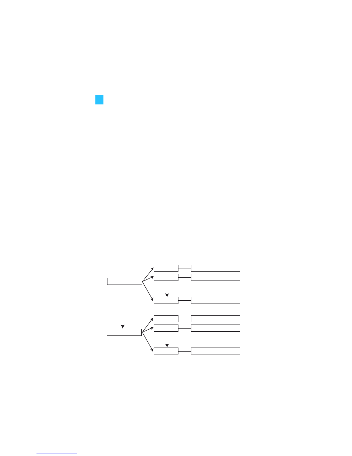
The channel bank system
The radiomicrophone is available in five UHF frequency
ranges with 1440 transmission frequencies per frequency
range. Please note: Frequency usage is different for each
country. Your Sennheiser agent will have all the necessary
details on the available legal frequencies for your area.
Range A: 518 to 554 MHz
Range B: 626 to 662 MHz
Range C: 740 to 776 MHz
Range D: 786 to 822 MHz
Range E: 830 to 866 MHz
The radiomi crophone h as nine channel bank s with u p to 20
switchable chann els each.
Each of the channels in the channel banks “1” to “8” has
been factory-preset to a transmission frequency (see
enclosed frequency table). These transmission frequencies
cannot be changed but have been preset so that e.g.
country-specific regulations on frequency usage are taken
into account.
The chan nel bank “U” (user b ank) allows you to store your
channel bank 1...8
channel bank U
channel 20
preset frequency
channel 1
channel 2
preset frequency
preset frequency
channel 20
channel 1
channel 2
freely selectable frequency
freely selectable frequency
freely selectable frequency

5
selection out of 1440 transmission frequencies that are
freely selectable within the preset frequency range.
Safety instructions
Never open an electronic unit! If units are opened by
customers i n breach of this instr uction, the warranty
becomes null and void.
Use the unit in dry rooms only.
Use a damp cloth for cleaning the unit. Do not use any
cleansing agents or solvents.
Delivery includes
Th e pac kaging contai ns the following items:
y 1 SKM 500 G2 radiomi crophone
y 2 batteries
y 1 microphone clamp
y Instructions for use
y 1 pou ch

6
Areas of application
The SKM 500 G2 radiomicrophone family can be combined
with receivers of the ew 500 G2 series (EM 500 G2 rackmount receiver or EK 500 G2 bodypack receiver). The
receivers are available in the same five UHF frequency
ranges and are equipped with the same channel bank
system with factory-preset frequencies. An advantage of
the factory-preset frequenc ies is that
y a transmission system is ready for immediate use after
switch-on,
y several transm ission sys tems can be operated simultane-
ously on the preset frequencies without causing intermodulation interference.
Together with a matching receiver, the radiomicrophone is
suitable for the follo wing areas of application:
The name1) of the radiomicrophone is a combination of the
name of the transmitter and the name of the microphone
head:
Transmitter+Microphone head = Name of radiomicrophone
SKM 500 +MD 835 = SKM 535
Each microphone head comes with a color-coded
identification ring to distinguish different microphone
heads from each other.
2)
only avi lable a s optional microphone head
Transmitter Receiver (to be
ordered separately)
Area of
application
SKM 535 G2
1)
SKM 545 G2
1)
SKM 565 G2
1)
EM 500 G2
y Presen tat ion
y Vocals
EK 500 G2
y Spe ec h
y Vocals
y Presen tat ion
y Came ra- mounted
applications
Mi cr o p ho ne
hea d
Co lo r of i
den tific atio n ring
Transducer
princi ple
Picxk-up
pattern
Area o f
application
MD 835 green dynamic cardioid Speech, vocals
MD 845 blue dynamic super-
cardioid
Vocals (high
feedback rejection)
ME 865 red condenser super-
cardioid
Vocals (
high
feedback rejection)
MMD 935
2)
(o ptio na l)
silver dynamic cardioid Vocals (in venues
with high ambient
noise levels)
7
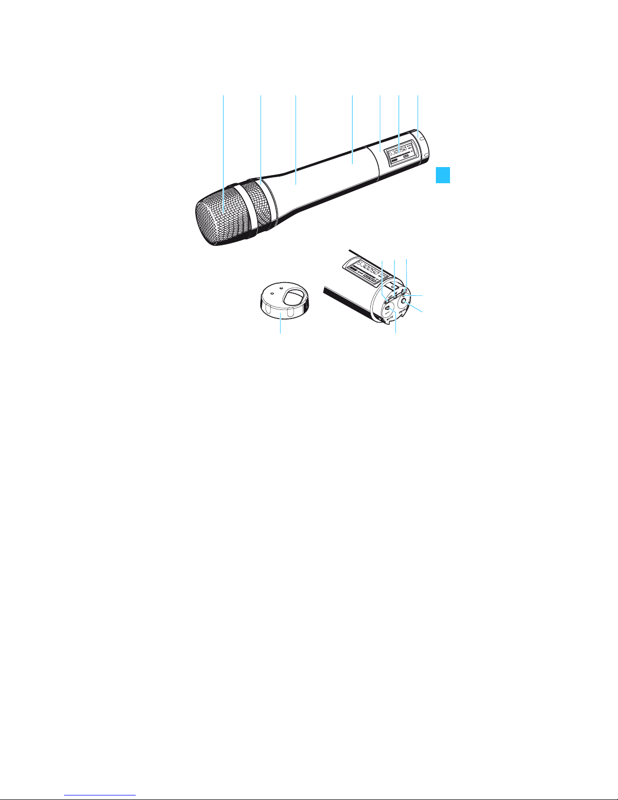
The operating controls
Sound inlet basket
Color-coded identification ring for microphone hea ds
green: MD 835 microphone head
blue: MD 845 micropho ne head
red: ME 865 mic rop ho ne h ead
Body of radiomicrophone
Battery compartment (not visible from outside)
Display section
LC display
Turnable protective cap for operating controls (shown
removed)
The follo wing operating c ontrols become acc essi ble in
turn by turning the protective cap:
SET bu tton
button (DOWN)
button (UP)
Red LED for operation and
battery status indication (ON/LOW BAT)
ON/OFF button
(serves as the ESC (cancel) key in the
operating menu)
MUTE switch
8
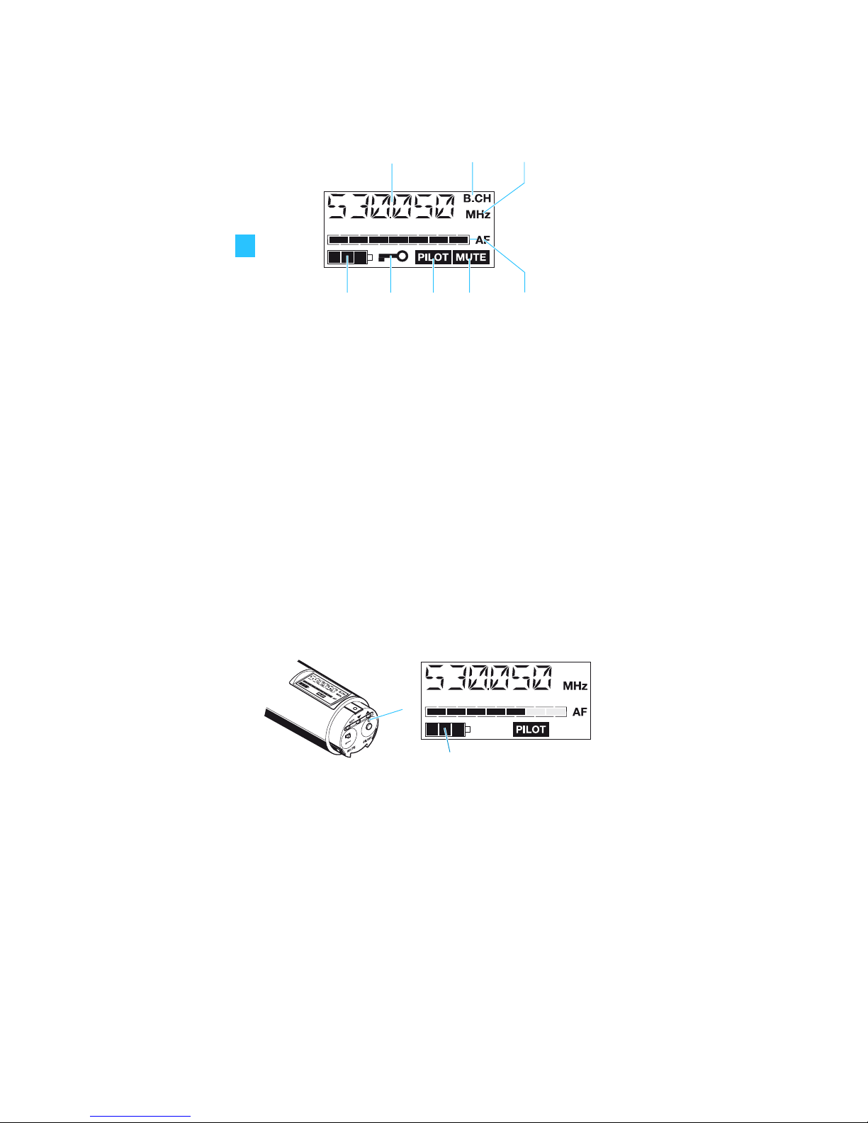
Indications and displays
LC di sp lay panel
Al phanum eric disp lay
“B.CH“ – appears when the channel bank and
the channel number are displayed
“MHz“ – appears when the frequency is displayed
4-step battery status display
Lo ck mo de i con
(lock mode is activated)
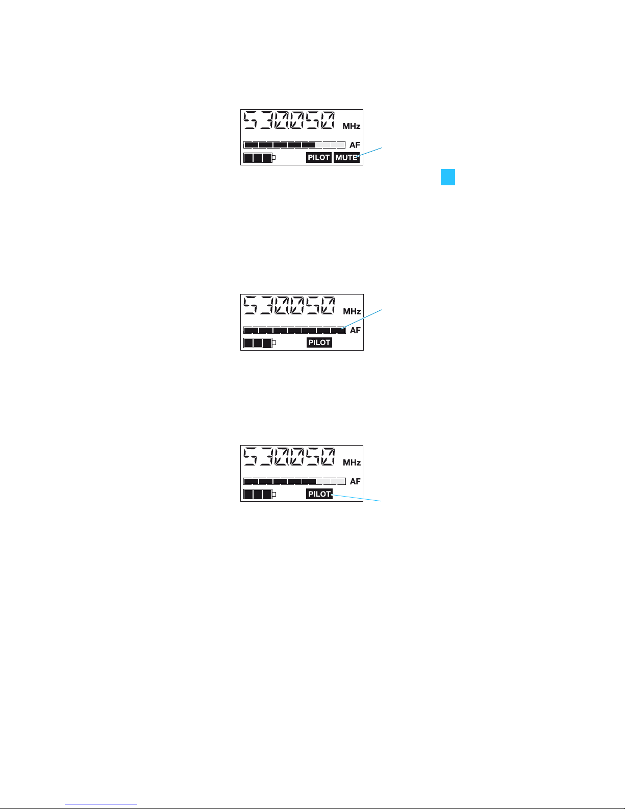
“PILOT” display
(pilot tone transmission is activated)
“MUTE” disp lay
(audio inpu t is muted)
7-step level display f or audio signal “AF”
Operation and battery status indication
The red LED (LOW BAT/ON) provides information on the
current operating state of the radiomicrophone:
Red LED lit up: The radiomicrophone is switched
on and the capacity of the
batteries/BA 2015 accupack is
sufficient.
Red LED flashing: The batteries are/the BA 2015
accupack is going flat (LOW BAT)!
In addition, the 4-step battery status display on the
display panel provides information on the remaining
battery/BA 2015 accupack capacity:
3 segments: capacity approx. 100 %
2 segments: capacity approx. 70 %
1 segment: capac ity approx. 30 %
Battery icon flashing: LOW BAT
9
“MUTE” display
The “MUTE” display appears on the display panel when
the radiomicrophone is muted (see “Muting the
radiomi crophone” on pa ge 14).
Modulation display
The level display for audio signal “AF” shows the
modulation of the radiomicrop hone.
When the audio input level is excessively high, the level
display for au dio signal “AF” shows full d eflec ti on for the
duration of the overmodulation.
“PILOT” display
The “PILOT” display appears on the display panel when
the pilot tone transmission is activated (see “Activating/
deactivating the pilot tone transmission” on page 23).
Display backlighting
After pressing a button, the display remains backlit for
approx. 15 seconds.
10
Preparing the radiomicrophone
for use
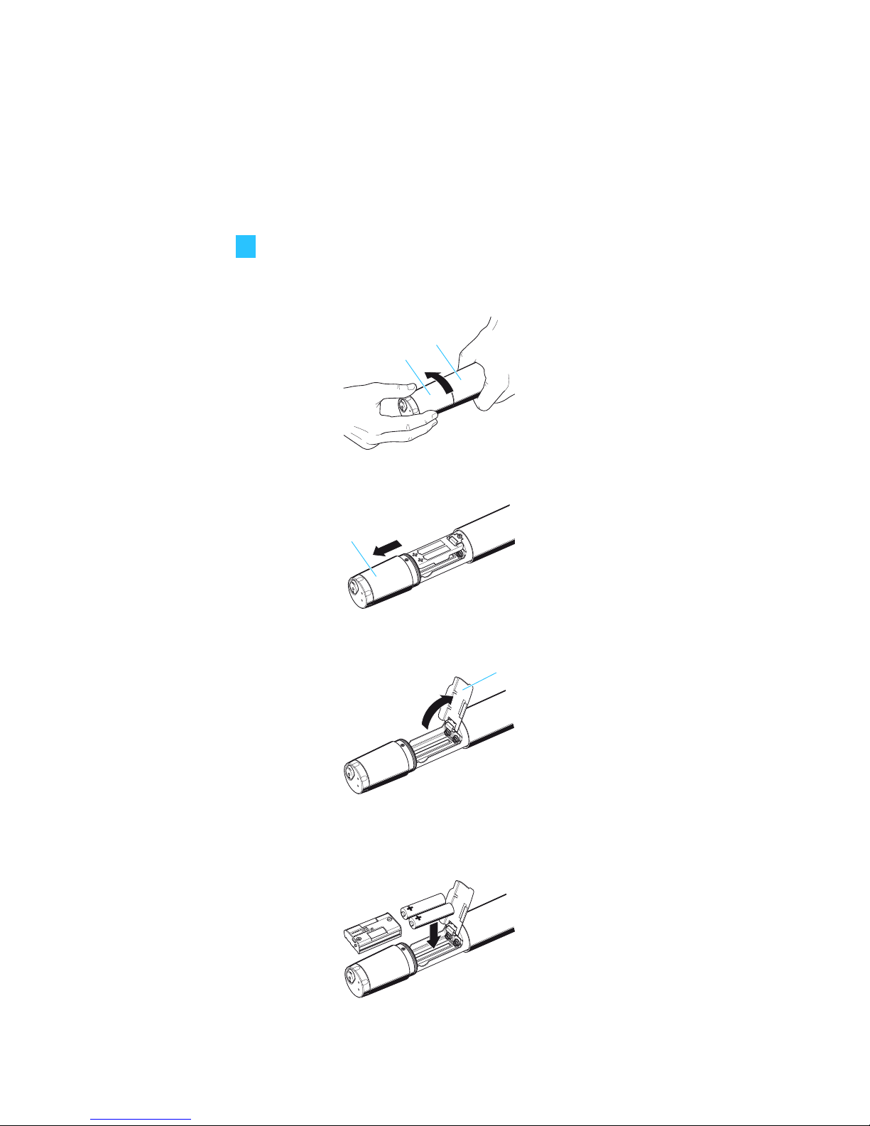
Inserting/replacing the batteries
For powering the radiomicrophone, you can either use two
1.5 V AA size batteries or the rechargeable Sennheiser
BA 2015 accupack.
Unscrew the display section from the
radiomicrophone’s body by turn ing it cou nterclockwise.
Slide back the display section as far as it will go.
Open the battery compartment cover .
Insert the two batteries or the BA 2015 accupack as
shown. Please observe correct polarity when inserting
the batteries/accu pack.
Close the battery compartment cover .
 Loading...