

Sennheiser 300 series, SKM 300 G4, 500 series, SKM 500 G4, EM 300 G4 Instruction Manual
...
evolution wireless G4
300 series / 500 series
Instruction Manual
Sennheiser electronic GmbH & Co. KG
Am Labor 1, 30900 Wedemark, Germany, www.sennheiser.com
ew 300-500 G4 - v1.1

Accessories
Accessories
A variety of accessories are available for the ew 300-500 G4 series.
Microphones and cables
Microphone modules
We recommend using the following microphone modules with the
SKM 300 G4 and SKM 500 G4 handheld transmitters.
►
Module Features Article
no.
MMD 835-1 BK Dynamic, cardioid, black 502575
MMD 845-1 BK Dynamic, super-cardioid, black 502576
MME 865-1 BK Capacitor, super-cardioid, black 502581
MMD 935-1 BK Dynamic, cardioid, black 502577
MMD 945-1 BK Dynamic, super-cardioid, black 502579
MMK 965-1 BK Capacitor, switchable
Cardioid/super-cardioid, black
MMK 965-1 NI Capacitor, switchable
Cardioid/super-cardioid, nickel
MD 9235 BK Dynamic, cardioid, black 502585
MD 9235 NI Dynamic, cardioid, black 502586
MD 9235 NI/BK Dynamic, cardioid, nickel/black 502591
Neumann
KK 204
Neumann
KK 204 BK
Neumann
KK 205
Neumann
KK 205 BK
Capacitor, cardioid, nickel 008651
Capacitor, cardioid, black 008652
Capacitor, super-cardioid, nickel 008653
Capacitor, super-cardioid, black 008654
502582
502584
You can find more information about the individual microphone modules on their respective product pages at www.sennheiser.com.
15

Accessories
Headset and Lavalier microphones
We recommend using the following Lavalier microphones and headset microphones with the SK 300 G4 and SK 500 G4 bodypack transmitters.
►
Microphone Features Article
no.
ME 2-II Lavalier microphone, omni-direc-
tional, black
ME 3-II Headset microphone, cardioid,
black
ME 4-N Lavalier microphone, cardioid,
black
MKE 1-ew Lavalier microphone, omni-direc-
tional, black
MKE 1-ew-3 Lavalier microphone, omni-direc-
tional, beige
MKE 2-ew Gold Lavalier microphone, omni-direc-
tional, black
MKE 2 ew-3 Gold Lavalier microphone, omni-direc-
tional, beige
MKE 40-ew Lavalier microphone, cardioid,
black
SL Headmic 1 BE Headband microphone, omni-di-
rectional,
beige
507437
506295
005020
502876
502879
009831
009832
500527
506272
SL Headmic 1 BK Headband microphone, omni-di-
506271
rectional,
black
SL Headmic 1 SB Headband microphone, omni-di-
506904
rectional,
silver
You can find more information about the individual microphones on
their respective product pages at www.sennheiser.com.
Line/instrument cables
The following cables are available to connect instruments and line sources
to the SK 300 G4 and SK 500 G4 bodypack transmitters:
• Sennheiser CL 2
Line cable with XLR-3F plug on lockable 3.5 mm jack plug, article no.
004840
• Sennheiser Ci 1-N
Guitar cable with 6.3 mm jack plug on lockable 3.5 mm jack plug, article
no. 005021
16

Accessories
Rechargeable battery and charger
BA 2015 rechargeable battery
The BA 2015 rechargeable battery is designed for use with evolution wireless G4 series handheld transmitters, bodypack transmitters and
bodypack receivers.
Article no. 009950
►
L2015 charger
The BA 2015 rechargeable battery can be charged in the L 2015 charger on
its own or inside of the bodypack transmitter/bodypack receiver.
Article no. 009828
►
17

Accessories
LA 2 charging adapter
Charging adapter for L 2015 charger for charging SKM G4 handheld transmitters with installed BA 2015 rechargeable battery.
Article no. 503162
►
18

Accessories
Accessories for rack mounting
GA 3 rack mount kit
19” rack adapter for mounting the EM 100 G4, EM 300 G4, EM 500 G4 or
SR 300 IEM G4 in a 19” rack.
Article no. 503167
►
AM 2 antenna front mounting kit
Antenna front mounting kit for installing antenna connections on the front
of the rack when using the EM 100 G4, EM 300 G4, EM 500 G4 or
SR 300 IEM G4 together with the GA 3 rack mounting kit.
Article no. 009912
►
►
19

Accessories
Antennas and accessories
The following antenna components are available as accessory parts.
Omni-directional antennas
• A 1031-U, passive omni-directional antenna, article no. 004645
Directional antennas
• A 2003 UHF, passive directional antenna, article no. 003658
Antenna splitter
►
• ASA 214, active antenna splitter 2×1:4
• ASA 214-UHF variant, 470 – 870 MHz, article no. 508241
Antenna amplifiers
• AB 3700, broadband antenna amplifier, article no. 502196
• AB 4, antenna amplifier, up to 88 MHz bandwidth
Available from the end of 2018
20

Accessories
Additional accessories
Color labeling set
• KEN 2, color labeling set for SKM handheld transmitters, article no.
530195
►
Microphone clamp
• MZQ 1, microphone clamp for SKM handheld transmitters, article no.
076670
►
MUTE switch
• RMS 1, remote mute switch for SK 300 G4, article no. 503164
►
21
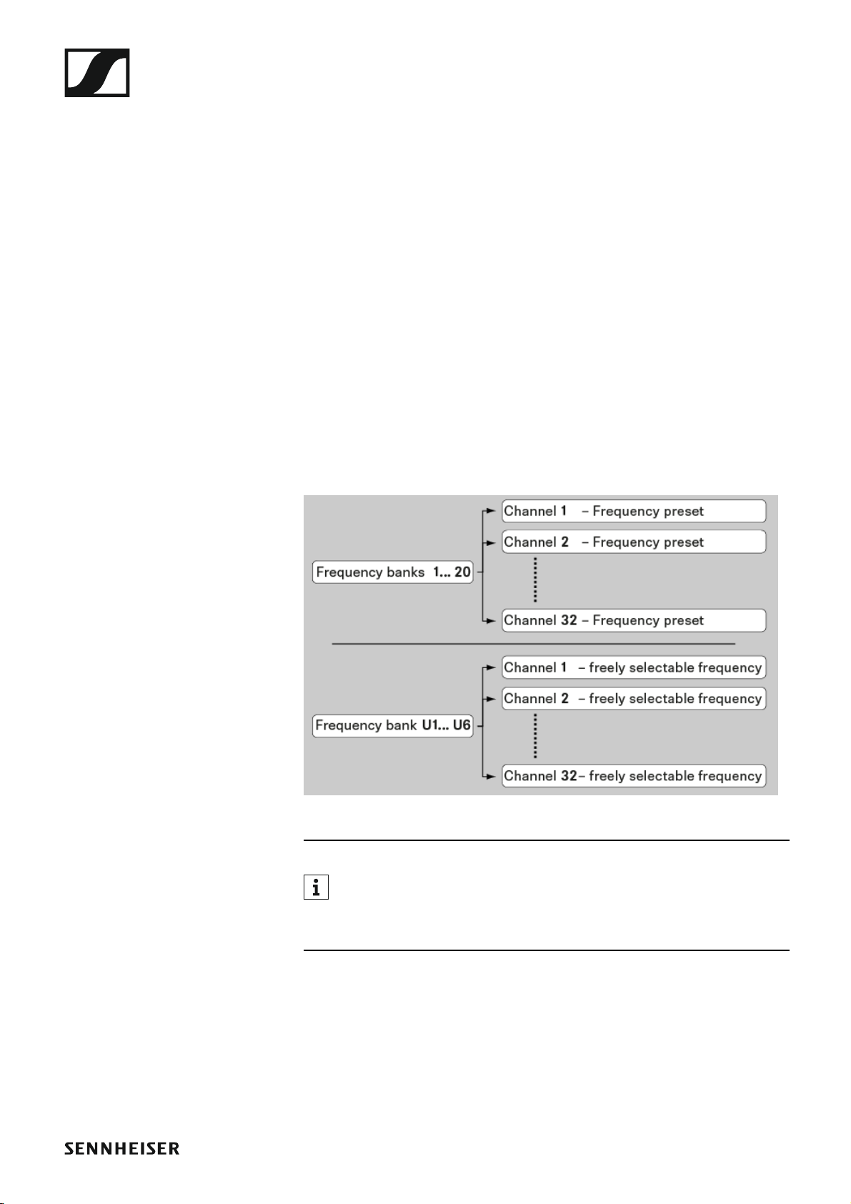
The frequency bank system
The frequency bank system
There are different frequency ranges in the UHF band available for transmission.
The following frequency ranges are available for the ew 300-
500 G4 series:
• Aw+ range: 470 – 558 MHz
• AS range: 520 – 558 MHz
• Gw1 range: 558 – 608 MHz
• Gw range: 558 – 626 MHz
• GBw range: 606 – 678 MHz
• Bw range: 526 – 698 MHz
• Cw range: 718 – 790 MHz
• Dw range: 790 – 865 MHz
• JB range: 806 – 810 MHz
• K+ range: 925 – 937.5 MHz
Every frequency range has 26 frequency banks with up to 32 channels:
►
You can find information about the frequency presets in the frequency tables of the respective frequency ranges under “Frequency tables”.
22
Installing the EM 300-500 G4
Installing the EM 300-500 G4
These sections contain detailed information about installing and starting
up the EM 300-500 G4.
You can find information about operating the EM 300-500 G4 under “Using
the EM 300-500 G4”.
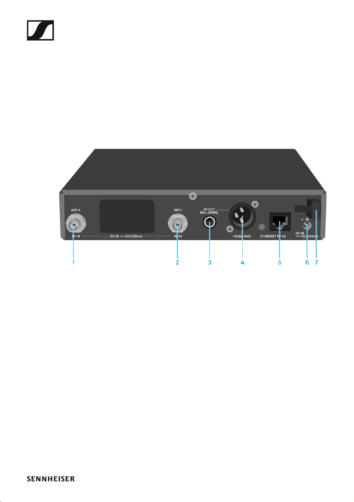
Connectors on the rear of the device
Product overview for the rear of the EM 300-500 G4
►
1 BNC socket, antenna input II (ANT II) with remote power supply unit
• See “Connecting antennas”
2 BNC socket, antenna input I (ANT I) with remote power supply unit
• See “Connecting antennas”
3 6.3 mm jack socket for audio output, unbalanced (AF OUT UNBAL)
• See “Outputting audio signals”
4 XLR-3 socket for audio output, balanced (AF OUT BAL)
• See “Outputting audio signals”
5 LAN connection socket (ETHERNET RJ 45)
• See “Creating a data network”
6 Connecting cables for the power supply unit (DC IN)
• See “Connecting/disconnecting the EM 300-500 G4 to/from the
power supply system”
7 Strain relief for the cable of the power supply unit
• See “Connecting/disconnecting the EM 300-500 G4 to/from the
power supply system”
25

Installing the EM 300-500 G4
Connecting/disconnecting the EM 300-500 G4 to/
from the power supply system
Only use the supplied power supply unit. It is designed for your receiver
and ensures safe operation.
To connect the EM 300-500 G4 to the power supply system:
▷ Insert the plug of the power supply unit into the DC IN socket of the re-
ceiver.
▷ Pass the cable of the power supply unit through the cable grip.
▷ Slide the supplied country adapter onto the power supply unit.
▷ Plug the power supply unit into the wall socket.
To completely disconnect the EM 300-500 G4 from the power supply system:
▷ Unplug the power supply unit from the wall socket.
▷ Unplug the power supply unit from the DC IN socket of the receiver.
26

Installing the EM 300-500 G4
Creating a data network
You can monitor and control one or more EM 300-500 G4s via a network
connection using Sennheiser Wireless Systems Manager (WSM) software.
Automatic frequency setup can also be performed over the network
without the WSM software. See “Easy Setup menu item”.
To connect the EM 300-500 G4 to a network:
▷ Connect a network cable with an RJ-45 connector (to the Ethernet
socket on the rear side of the EM 300-500 G4.
▷ Connect the other end of the network cable to a network switch.
►
For more information about controlling devices via the Sennheiser
Wireless Systems Manager (WSM) software, refer to the instruction manual for the software. You can download the software here:
www.sennheiser.com/wsm
27

Installing the EM 300-500 G4
Outputting audio signals
The EM 300-500 G4 has a balanced XLR-3M output socket and an unbalanced 6.3 mm jack output socket.
▷ Always use only one of the two BAL AF OUT output sockets for each
channel.
To connect an XLR cable:
▷ Plug the XLR cable into the AF OUT BAL socket of the EM 300-500 G4.
To connect a jack cable:
▷ Plug the jack cable into the AF OUT UNBAL socket of the EM 300-
500 G4.
28

Installing the EM 300-500 G4
Connecting antennas
To connect the supplied rod antennas:
▷ Connect the first rod antenna to the ANT I socket on the rear side of the
EM 300-500 G4.
▷ Connect the second rod antenna to the ANT II socket on the rear side
of the EM 300-500 G4.
▷ Gently angle the rod antennas to the left and right as shown in the fig-
ure.
If you are using more than one receiver, we recommend using remote
antennas and, as needed, Sennheiser antenna accessories. For more
information, visit the ew G4 product page at www.sennheiser.com.
29

Installing the EM 300-500 G4
Installing the EM 300-500 G4 in a rack
CAUTION
Rack mounting poses risks
When installing the device in a closed or multi-rack assembly, please consider that, during operation, the ambient temperature, the mechanical
loading and the electrical potentials will be different from those of devices
which are not mounted into a rack.
▷ Make sure that the ambient temperature within the rack does not ex-
ceed the permissible temperature limit specified in the specifications.
See “Specifications”.
▷ Ensure sufficient ventilation; if necessary, provide additional ventila-
tion.
▷ Make sure that the mechanical loading of the rack is even.
▷ When connecting to the power supply system, observe the information
indicated on the type plate. Avoid circuit overloading. If necessary, provide overcurrent protection.
▷ When rack mounting, please note that intrinsically harmless leakage
currents of the individual power supply units may accumulate, thereby
exceeding the allowable limit value. As a remedy, ground the rack via
an additional ground connection.
30

Installing the EM 300-500 G4
Mounting a single receiver in a rack
To mount the receiver in a rack, you will need the GA 3 rack mounting kit
(optional accessory).
To fasten the mounting angle of the GA 3 rack mounting kit:
▷ Unscrew and remove the two recessed head screws (M4x8) on each
side of the receiver.
▷ Secure both of the the mounting angles to the sides of the receiver us-
ing the previously removed recessed head screws.
▷ Secure the blanking plate to one of the mounting angles using two re-
cessed head screws (M6x10).
▷ Attach the AM 2 antenna front mounting set (optional accessory) and
mount the rod antennas on the blanking plate (right diagram).
▷ Slide the receiver with the mounted blanking plate into the 19" rack.
▷ Secure the mounting angle and the blanking plate to the 19" rack.
▷ Align the mounted antennas in a V-shape.
31

Installing the EM 300-500 G4
Mounting two receivers side by side in a rack
When you mount two receivers side by side, it is only possible to front
mount antennas when you use the ASA 214 antenna splitter in combination with the AM 2 front mounting kit and an additional GA 3 rack
mounting kit. See “Installing the ASA 214”.
To mount the receiver using the GA 3 rack mounting kit (optional accessory):
▷ Place both receivers upside down and side by side on an even surface.
▷ Secure the jointing plate to the transmitters using the six recessed
head screws (M3x6).
▷ Secure the mounting angle.
32

Installing the SKM 300 G4
Installing the SKM 300 G4
These sections contain detailed information about installing and starting
up the SKM 300 G4.
You can find information about operating the SKM 300 G4 under “Using
the SKM 300 G4”.
Inserting and removing the batteries/rechargeable
batteries
You can operate the wireless microphone either with batteries (AA, 1.5 V)
or with the rechargeable Sennheiser BA 2015 battery.
▷ Screw the rear part of the wireless microphone in the direction of the
arrow (counter-clockwise) off of the handle of the wireless microphone.
When you remove the wireless microphone during operation, mute is
automatically activated. MUTE appears in the display panel. When
you screw the microphone back together, mute is deactivated.
▷ Pull the rear part of the wireless microphone all the way out.
▷ Open the cover of the battery compartment.
▷ Place the batteries or the BA 2015 rechargeable battery in the battery
compartment as shown on the cover. Please observe correct polarity
when inserting the batteries/accupack.
▷ Close the cover.
▷ Push the battery compartment into the handle of the wireless micro-
phone.
▷ Screw the rear part of the wireless microphone back onto the handle.
33
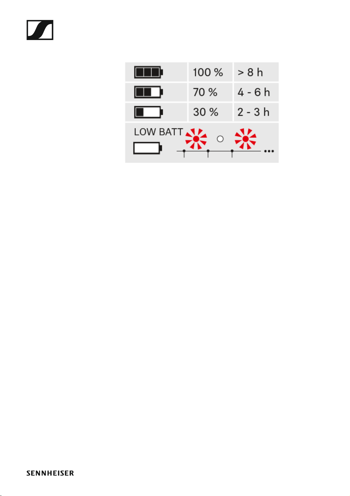
Battery status
Charge status of the batteries:
►
Installing the SKM 300 G4
Charge status is critical (LOW BATT):
►
34

Installing the SKM 300 G4
Replacing the microphone module
You can find a list of the recommended microphone modules for the handheld transmitter under “Microphones and cables”.
To change the microphone module:
▷ Unscrew the microphone module.
▷ Screw the desired microphone module on.
►
Do not touch the wireless microphone contacts or the microphone
module contacts. If you touch the contacts, they may become dirty or
bent.
When you unscrew the microphone module during operation, mute is automatically activated. MUTE appears in the display panel. When you screw
the microphone module back on, mute is deactivated.
35

Installing the SKM 300 G4
Changing the colored ring
To change the colored ring:
▷ Pull the colored ring off as shown in the diagram.
►
▷ Attached a colored ring in the color you want as shown in the diagram.
►
36
 Loading...