

Senix CHEM 10, CHEM 20, CHEM 35 Operating Manual
ToughSonic® CHEM Series
Ultrasonic Level Sensors
PC Configurable
Chemically Resistant
Multiple Outputs
ToughSonic CHEM 10
ToughSonic CHEM 20
ToughSonic CHEM 35
Installation and Operating Instructions
Senix Corporation
Date: May 31, 2015
2015 by Senix Corporation

ToughSonic® LVL Family Sensors - Installation & Operating Instructions
ToughSonic ® CHEM Family Sensors – Installation & Operating Instructions
Warranty
Product
Declarations
Document Revisions
Initial release 31 May 2015
Related Products
SenixVIEW for Windows
A setup tool for TSPC and
CHEM series sensors, this
software installs on a PC and is
used to configure sensor
options, select and calibrate
outputs, view and analyze
measurements, and save the result to a PC hard drive.
Recalled configurations can restore or duplicate an
application without recalibration. View, chart, log,
and analyze sensor operation. Sensor firmware
upgrades can be done easily through SenixVIEW too.
Download SenixVIEW at no charge from:
http://senix.com/download-3.htm.
Setup Kits
Used for bench viewing or configuring sensors, kits
include power supply, terminal board and cables to
interconnect with your PC. A SenixVIEW CD with
software, videos and manuals is also included (see
Software and Interconnection, page 10).
Senix makes no warranty, representation, or
guarantee regarding the suitability of the products for
any particular purpose. All specifications are subject
to change without notice.
Senix, Inc. will repair or replace, at our option, any
part found by us to be defective in material or
workmanship if the product is received by Senix,
freight prepaid, within one year from the date of
original shipment to buyer.
Disclaimer and Release. The warranties, obligations
and liabilities of Senix and the remedies of buyer set
forth above are exclusive and in substitution for, and
buyer hereby waives, releases and renounces all other
warranties, obligations and liabilities of Senix and all
other rights, claim, and remedies of buyer against
Senix, expressed or implied, arising by law or
otherwise, including but not limited to: (A) Any
implied warranty or merchantability or fitness; (B)
Any implied warranty arising from course of
performance, course of dealing or usage of trade; (C)
Any obligation, liability, right, claim or remedy in
tort, whether or not arising from the negligence of
Senix (whether active, passive or imputed); and (D)
Any obligation, liability, right, claim or remedy for
loss or damage to any product.
Exclusion of Consequential and Other Damages.
Senix shall have no obligation or liability, whether
arising in contract (including warranty), tort
(including active, passive or imputed negligence) or
otherwise, for loss of use, revenue or profit with
respect to any nonconformance or defect in any
product delivered under this agreement, or for any
other direct, incidental or consequential damages.
Governing Law. The terms and conditions of this
agreement shall be governed by the domestic law of
the State of Vermont, U.S.A.
CE Compliance
ToughSonic family of ultrasonic sensors are
compliant with the CE Electromagnetic
Compatibility Directives and Standards listed below:
Directives: Electromagnetic Compatibility
(2004/108/EC)
Low-Voltage (2006/95/EC)Standards: EMC: EN
61326-1:2006 Industrial Safety: EN 61010-1:2001
Senix Corporation, 10516 Route 116 Suite 300, Hinesburg, VT 05461 USA
802.489.7300 or 800.677.3649, FAX: 802.489.7400, Web: www.senix.com, e-mail: support@senix.com
Page 2 of 38 – May 31, 2015
Repairs and Returns
Any returns must have a Return Material
Authorization (RMA) number. Contact us at:
Mail: Senix Corporation
10516 Route 116 Suite 300
Hinesburg, VT 05461 USA
Phone: 802.489.7300 or 800.677.3649
FAX: 802.489.7400
e-mail: support@senix.com web: www.senix.com

ToughSonic® LVL Family Sensors - Installation & Operating Instructions
ToughSonic ® CHEM Family Sensors – Installation & Operating Instructions
TABLE OF CONTENTS
PRODUCT DECLARATIONS .................... 2
Document Revisions _______________________ 2
Related Products __________________________ 2
CE Compliance ___________________________ 2
Warranty ________________________________ 2
Repairs and Returns _______________________ 2
ULTRASONICS OVERVIEW ..................... 4
Introduction ______________________________ 4
Advantages ______________________________ 4
Other Applications _________________________ 4
Terminology _____________________________ 5
SENSOR OVERVIEW ................................ 6
CHEM Product Features ____________________ 6
Specifications ____________________________ 6
Startup Tips ______________________________ 8
Mechanical Details ________________________ 9
Installation _______________________________ 9
INTERFACES .......................................... 11
Wiring _________________________________ 11
Analog Outputs __________________________ 12
Switch Outputs __________________________ 14
Serial Data Interface ______________________ 17
Serial Parameters ________________________ 18
Serial Data Protocols _____________________ 19
OPERATION ........................................... 20
Power Up ______________________________ 20
Measurement Activation ___________________ 20
Synchronization__________________________ 20
Operating Range _________________________ 21
Measurement Process ____________________ 22
Sensor Viewing __________________________ 22
Measurement Rate _______________________ 24
Output Response Time ____________________ 24
Filters _________________________________ 25
Time Delays ____________________________ 28
Temperature Compensation ________________ 28
Appendix A – List of Adjustable Features ______ 34
LIST OF FIGURES
Figure 1 - Part Number Structure ............................... 6
Figure 2 – Housing Dimensions .................................. 9
Figure 3 - Sensor Orientation ..................................... 9
Figure 4 – Flange Mounting ..................................... 10
Figure 5 - Nipple Mounting ...................................... 10
Figure 6 - RS-232 PC COM Port Connections ............ 11
Figure 7 - Voltage Output Wiring ............................ 12
Figure 8 - Sourcing Current Loop Wiring .................. 12
Figure 9 - Sinking Current Loop Wiring .................... 12
Figure 10 - SenixVIEW Analog Adjustments ............. 13
Figure 11 - Sinking Switch Output Wiring ................ 14
Figure 12 - Sourcing Switch Output Wiring .............. 14
Figure 13 - Switch Hysteresis & Window Modes...... 15
Figure 14 - SenixVIEW Switch Adjustment ............... 16
Figure 15 - RS-232 PC COM Port Connections .......... 17
Figure 16 - LVL-xxxx-232 Connections...................... 17
Figure 17 - LVL-xxxx-485 Connections...................... 17
Figure 18 - RS-485 Network Wiring ......................... 17
Figure 19 - Measurement Activation Selections ...... 20
Figure 20 - SenixVIEW Polling Controls .................... 21
Figure 21 - Measurement Process Diagram............. 22
Figure 22 - SenixVIEW Distance Displays ................. 22
Figure 23 - Filters Block Diagram ............................. 25
LIST OF TABLES
Table 1 - Specifications _______________________ 7
Table 2 - Wire Assignments __________________ 11
Table 3 - Measurement Activation Summary ____ 20
Table 4 - Maximum Range vs. Measure Rate ____ 24
Table 5 - Filter Response Time ________________ 27
SENIXVIEW SOFTWARE ........................ 29
Install SenixVIEW ________________________ 29
Application Setups _______________________ 29
Connect a Sensor ________________________ 30
Outputs ________________________________ 31
Sensor Adjustment _______________________ 33
Senix Corporation, 10516 Route 116 Suite 300, Hinesburg, VT 05461 USA
802.489.7300 or 800.677.3649, FAX: 802.489.7400, Web: www.senix.com, e-mail: support@senix.com
Page 3 of 38 – May 31, 2015
ToughSonic® LVL Family Sensors - Installation & Operating Instructions
ToughSonic ® CHEM Family Sensors – Installation & Operating Instructions
( 2 ) U l t r a s o n i c e c h o r e t u r n s f r o m t a r g e
t
( 1 ) U l t r a s o n i c p u l s e t r a n s m i t t e d f r o m s e n s o r
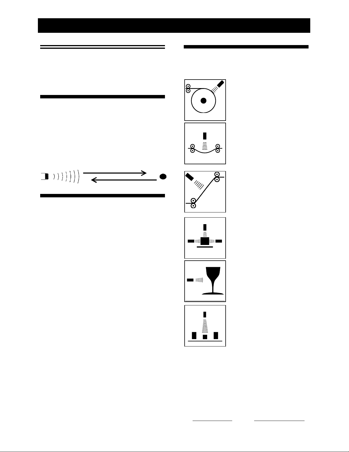
Other Applications
Ultrasonics
In addition to level control our ultrasonic sensors can
be used in many other applications such as:
Overview
Introduction
Senix sensors measure the distance to a liquid or
solid surface by sending a sound wave, above the
range of hearing, at the target surface and measuring
the time for the sound echo to return. Knowing the
speed of sound, the sensor determines the distance of
the target, and inversely the level.
Advantages
Non-contact
Measures through the air without touching the
target material.
Easy to Install
Threaded mounting from above means simple
installation without entering the tank.
Point Level Outputs
Solid state switch outputs provide control or
alarm features that are user selectable.
Roll Diameter
Measure the size of a roll to
control tension or speed, or
determine when full or empty.
Loop Control
Precisely control the position of
material loops, including wires,
tubes and webs.
Web Break
Rapidly detect a broken web in a
printing press or paper machine.
Dimensioning
Determine the size of an object
for information or to determine
its volume or width.
Proximity
Determine the presence of
objects to count or control their
movement.
Distance Proportional Outputs
Three proportional analog outputs provide
standard interfaces to PLCs or displays.
Unaffected by Target’s Optical
Characteristics
Sensor operation is not sensitive to ambient light
levels, the color of the target, or whether the
target is optically transparent or reflective.
Remote Adjustment
SenixVIEW software allows remote monitoring
and adjustment for convenience and safety.
Senix Corporation, 10516 Route 116 Suite 300, Hinesburg, VT 05461 USA
802.489.7300 or 800.677.3649, FAX: 802.489.7400, Web: www.senix.com, e-mail: support@senix.com
Page 4 of 38 – May 31, 2015
Sort/Select
Sort or select objects based on
differences in their physical
dimensions ….and many more...

ToughSonic® LVL Family Sensors - Installation & Operating Instructions
ToughSonic ® CHEM Family Sensors – Installation & Operating Instructions
information using serial data communications. This is
Terminology
Terms listed here are shown in italics throughout this
document. An asterisk (*) indicates a SenixVIEW
configurable parameter.
Analog An electrical output type that varies in proportion
to measured distance. Analog output types can be
either current loop or voltage.
Analog Window* A range of distances between two
endpoints, within which the analog output will vary
between the analog high and low limits in proportion
to measured distance.
Current High Value* The maximum (highest) value of
both current loop outputs, typically 20 mA but
adjustable using SenixVIEW.
Current Loop Output* An analog output type that
drives an electrical current proportional to measured
distance. CHEM sensors provide two standard 4-20
mA (sourcing and sinking) or SenixVIEW customized
output ranges.
Current Low Value* The minimum (lowest) value of
both current loop outputs, typically 4 mA but
adjustable using SenixVIEW.
Deadband The small distance near the sensor face within
which distance cannot be measured.
Endpoint* One of two end distances representing the
outer limits of the analog window.
Hysteresis* The reverse distance a target must change to
turn a switch OFF after the switch has turned ON at a
Setpoint.
Ingress Rating An enclosure rating that identifies how
susceptible a product is to the entry (ingress) of
external objects or liquids.
Measurement Rate* The repetitive rate that the sensor
measures distance (see response time).
Measurement Interval* The time between
measurements, or [1 / Measurement Rate].
Measurement Process* The measurement, filtering and
time delays that affect sensor outputs (p 22).
Maximum Range The maximum target detection distance
of a sensor model; may be overridden by Range MAX
(p 21).
Operating Range* The range of distances between the
range MIN and range MAX values (p 21).
Optimum Range The range of target distances
recommended for optimum performance in varying
environmental conditions.
Range MAX* The farthest distance of the Operating
Range; user adjustable in SenixVIEW.
Range MIN* The nearest distance of the Operating
Range; user adjustable in SenixVIEW.
RS-232* An electrical interface standard used to transfer
information using serial data communications. This is
a single ended interface with a specified maximum
range of 50 feet (15 meters) that typically supports one
device.
RS-485* An electrical interface standard used to transfer
a long distance differential interface capable of
supporting multiple addressable devices.
Response Time* The time required for sensor outputs to
respond to measurements; affected by measurement
rate and filter selections.
Serial Data A method of transferring information using a
sequential (serial) on/off pattern to encode the data.
Two common industry standards are RS-232 and RS-
485.
Setpoint* The distance a switch output turns ON.
Sinking Current Loop* (vs. sourcing current loop)
Analog 4-20 mA output where the current source is
external and the sensor sinks that current loop to
ground.
Sinking Switch* (vs. Sourcing Switch) One that sinks
current from an external load to ground when turned
ON. An ON sinking switch output measures a low
voltage.
SenixVIEW Senix PC-based software used to configure
and ToughSonic® sensors.
Sourcing Current Loop* (vs. sinking current loop)
Analog 4-20 mA output where the sensor is the source
of current that flows out of the sensor.
Sourcing Switch* (vs. Sinking Switch) One that sources
current from the sensor to the load when turned ON.
An ON sourcing switch output measures a high
voltage.
Switch* An electrical output type that is either ON or
OFF. ToughSonic® switches are solid state and can be
either sinking or sourcing type.
SYNC* A wired configuration that synchronizes the
timing of two or more sensors to prevent crosstalk or
ensure simultaneous measurements. This feature is
generally not used in level measurement applications.
Target Any object or material that reflects ultrasonic
energy back to the sensor thus allowing the sensor to
measure its distance.
Time Delay* A time period triggered by a set of
conditions and, after those conditions persist for the
entire period, cause a secondary event to occur. There
are several user-selected time delay features available.
Ultrasonic A sound wave of a frequency greater than
20,000 Hz, typically above the range of human
hearing.
Voltage High Value* The maximum (highest) value of
the voltage outputs, typically 10 VDC but adjustable
using SenixVIEW.
Voltage Low Value* The minimum (lowest) value of the
voltage output, typically 0 VDC but adjustable using
SenixVIEW.
Voltage Output* An analog output type that drives an
electrical voltage proportional to measured distance.
CHEM series sensors provide industry standard or
SenixVIEW customized output ranges.
Senix Corporation, 10516 Route 116 Suite 300, Hinesburg, VT 05461 USA
802.489.7300 or 800.677.3649, FAX: 802.489.7400, Web: www.senix.com, e-mail: support@senix.com
Page 5 of 38 – May 31, 2015
ToughSonic® LVL Family Sensors - Installation & Operating Instructions
ToughSonic ® CHEM Family Sensors – Installation & Operating Instructions
Switches
> Sinking (NPN) or Sourcing (PNP)
> 2 switches, overload protected
> Reversible polarity (NO/NC)
> Adjustable responses and delays
Serial Data
> RS-232 and RS-485 models
> Modbus or ASCII streaming
> Adjustable baud rate & address
> Multi-drop addressable (RS-485)
Current Loops
> 4-20 mA or custom mA range
> Independent sourcing and sinking
current loops
> Positive or negative slope
> Adjustable responses and delays
Voltage
> 0-5, 0-10 or custom VDC range
> Positive or negative slope
> Adjustable responses and delays
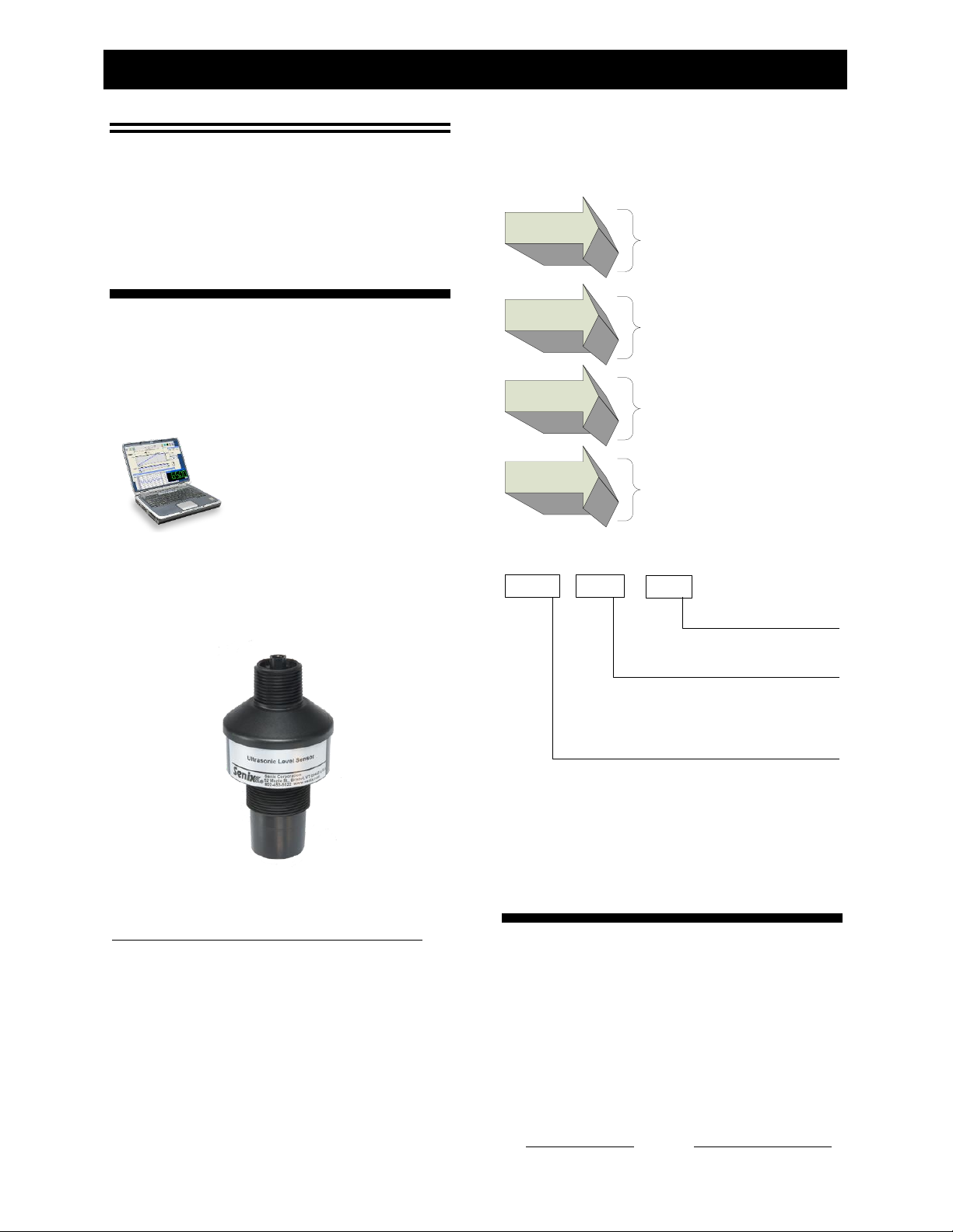
LVL - xxx - xxx
SERIAL DATA INTERFACE
232: RS-232 (PC COM port)
485: RS-485, addressable
SERIES (varies by range)
100: 1.5-in NPT thread, 10-ft max. (3 m)
300: 1.5-in. NPT thread, 20-ft max. (6 m)
500: 2.0-in. NPT thread, 35-ft max. (10m)
PRODUCT FAMILY
LVL: ToughSonic® PC Configurable Level Sensor
Industry Standard Interfaces
Multiple simultaneous outputs, each with many
Sensor
SenixVIEW adjustable features.
Overview
CHEM Product Features
ToughSonic CHEM sensors measure distance
without contact and are designed for tough industrial
environments.
Rapid PC Setup & Control
PC setup gives you control
over all sensor outputs and
features. View, analyze and
save sensor setups for rapid
implementation or cloning.
Chemically Resistant Packaging
Rugged Kynar® PVDF housings are completely
sealed and impervious to most chemicals and operate
over a wide temperature range. A PUR jacketed
interface cable is potted into each housing.
CHEM Series Part Numbers
Figure 1 - Part Number Structure
Identification
The ToughSonic model number and serial number
KYNAR® is a registered trademark of Arkema Inc.
For chemical resistance information refer to
www.arkemainc.com/kynar/literature/pdf/754.pdf.
802.489.7300 or 800.677.3649, FAX: 802.489.7400, Web: www.senix.com, e-mail: support@senix.com
Senix Corporation, 10516 Route 116 Suite 300, Hinesburg, VT 05461 USA
Page 6 of 38 – May 31, 2015
are printed on the label on the side of the housing.
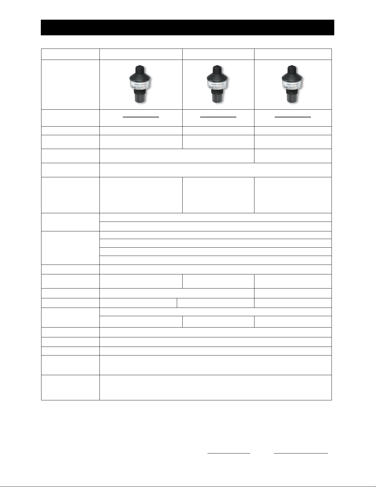
Specifications
A summary of sensor specifications is shown in the
following table.
ToughSonic® LVL Family Sensors - Installation & Operating Instructions
ToughSonic ® CHEM Family Sensors – Installation & Operating Instructions
ToughSonic CHEM 10
ToughSonic CHEM 20
ToughSonic CHEM 35
Photo
RS-232 interface
RS-485 interface
LVL-100-232
LVL-100-485
LVL-300-232
LVL-300-485
LVL-500-232
LVL-500-485
Maximum Range
10 ft. (3.1 m)
20 ft. (6.1 m)
35 ft. (10.7 m)
Optimum
Range
4.0 in. (10.2 cm)
80 in. (203 cm)
8 in. (20.3 cm)
13 ft. (4.1 m)
12 in. (31 cm)
25 ft. (7.6 m)
Mounting, and
Dimensions (inches)
1.5-in. NPT lower thread for flange mounting
1.0-in NPT upper thread for suspended mounting
2.0-in. NPT lower thread,
1.0-in NPT upper thread
Parameter Adjustments
Permanently stored in sensor using SenixVIEW software. SenixVIEW is Windows XP (SP3),
Windows 7 & 8 compatible, and supports COM port addresses 1-99.
Default: RangeMIN
RangeMAX
Switch #1 Setpoint
Switch #2 Setpoint
Analog Low Endpoint
Analog High Endpoint
4.0 in. (10.2 cm)
10 ft. (3.1 m)
80 in. (203 cm)
8 in. (20.3 cm)
80 in. (203 cm)
4.0 in. (10.2 cm)
8 in. (20.3 cm)
20 ft. (6.1 m)
160 in. (406 cm)
18 in. (45.7 cm)
160 in. (406 cm)
8 in. (20.3 cm)
12 in. (31.5 cm)
35 ft. (10.7 m)
280 in. (711 cm)
18 in. (45.7 cm)
280 in. (711 cm)
12 in. (30.5 cm)
DC Current @
10-30 VDC input
Note: Add 20 mA if using sourcing current loop. Add switch loads if using sourcing switch(es).
45 mA typical
Outputs
(not including serial
data)
Five Outputs: 0-10 VDC, 4-20 mA sourcing, 4-20 mA sinking, two switches
Switches: 150 mA, SenixVIEW configured as PNP (@ input voltage) or NPN (external 40 VDC max.)
Voltage: 0-10 or 0-5 or SenixVIEW adjusted, 10 mA max (min 15 VDC input for full 10 VDC output)
Current Loop: 4-20 mA or SenixVIEW configured, 450 max @ >15VDC, 250 max @ 10 VDC
Resolution, analog
4100 steps 0-10 VDC and 3279 steps 4-20 mA (scaled between user-set distance endpoints)
Resolution
(serial data)
0.003384 in. (0.086 mm)
0.006768 in. (0.1719 mm)
0.013536 in. (0.3438 mm)
Weight
21.7 oz. 0.62 kg.
24.7 oz. 0.70 kg.
Ultrasonic Frequency
125 kHz
75 kHz
50 kHz
Measurement Interval
(Factory defaults)
(see pg.24)
Adjustable from 5 mS to 2.8 hours; affected by filter selections; faster rates limit max target distance
50 mSec
100 mSec
200 mSec
Environmental
Ingress: IP-68, NEMA-4X Humidity: 0-100% (avoid heavy condensation) Temp: -40 to +70 C operate
Transducer
Rugged piezoelectric, nominal beam width 12 degrees @ -3 db, approx. conical shaped pattern
Housing & Cable
Chemically resistant Kynar PVDF, potted-in 6.5 ft. (2 m) shielded PUR cable with tinned wire ends
Performance
Repeatability: Greater of +/-0.03 in. (0.76 mm) or 0.1% of target distance in stable environment
Accuracy: Better than 0.5% of target distance in stable, homogeneous environment; affected by
temperature gradients, target echo strength, speed of sound in vapors.
Serial Data Interface
RS-232 or RS-485 interface, depends on model. RS-485 models are 2-wire multi-drop addressable
(addresses 1-247). Baud rates 9600, 19200 or 38400, no parity, 8 bits, one stop bit. Protocol options
are Modbus slave or ASCII streaming. Serial data modes and parameters are configured with
SenixVIEW.
Table 1 - Specifications
Senix Corporation, 10516 Route 116 Suite 300, Hinesburg, VT 05461 USA
802.489.7300 or 800.677.3649, FAX: 802.489.7400, Web: www.senix.com, e-mail: support@senix.com
Page 7 of 38 – May 31, 2015

ToughSonic® LVL Family Sensors - Installation & Operating Instructions
ToughSonic ® CHEM Family Sensors – Installation & Operating Instructions
connection with any available green ports). For more
Startup Tips
New or first-time users can use this condensed guide for
assembly, connection to a PC, and basic sensor changes from
default values before installation.
The sensor communicates with a Windows PC through the
serial port or USB port. A UA-Kit from Senix is
recommended for connecting to your PC. It includes software,
a termination board, and cables (see page 10).
Identify System Components
a. Sensor with attached cable
b. Terminal board (basic or comprehensive)
c. Data communication cable
d. Adapter for a USB connection (if required)
e. SenixVIEW Software CD
f. Power supply kit for bench setup
Install the Software
Put the SenixVIEW CD into your CD drive. Open the CD
contents on you PC and run SenixVIEW Version 3.3.xxx
Setup.exe to install. Start SenixVIEW.
Connect the Components
The sensor uses colored wires for power, communication,
and outputs. For a basic terminal board connection, we’ll
use 4 of the sensor’s wires:
a. Brown for DC power (DC+)
b. Blue for ground (GND and digital reference)
c. Gray and Yellow for digital communication.
Connect them to the labeled Senix terminal board. Protect
all bare wires from contacting one another whether
connected or not. Ensure the terminal grips the stripped
wire, not its colored jacket.
Put the DC power supply cable into the jack on the
terminal board, and the supply into an AC source. All
sensors will faintly tick when powered.
Plug the data communication cable into the terminal board
RJ jack and your serial port (-232 models), or into the
USB adapter (optional for -232 and required for -485
models). (For USB adapters see page 10)
Connect to Your Sensor (using serial port)
1. Start SenixVIEW.
2. Menu bar: Sensor >Connect for a dialog box. All new
sensors have network address 1. Use Baud rate 9600.
The serial port is generally identified COM 1. Click
Connect.
OR Connect to Your Sensor (using a USB port)
1. Start SenixVIEW.
2. Menu bar: Sensor >Connect for a dialog box. All new
sensors have network address 1. Use Baud rate 9600.
The serial port number is above 1. Click the lowest
green COM port. Click Connect. Repeat on next green
COM port until sensor found. (If not found, Com port
might be higher than the 12 shown. Edit >User
Preferences…> Connection/ Starting COM port: and
enter 13. Return to Connect Sensor and repeat
detail, see “Connect a Sensor”, page 30.
SenixVIEW Quick Tour
Once a sensor is connected, it can be viewed in the
SENSOR view. Any changes are done in the
WORKSPACE view and transferred to the sensor.
Basic layout of the main screen:
a. Range and basic setup values, all editable.
b. Workspace and Sensor views
c. File saving and retrieval button
d. Dialog screens for additional setup
e. Analysis tools
f. Output setup and simulated meters (editable)
Setup Basics (advanced description starts page 22)
When sensor is found, answer YES to copy sensor setup to
the Workspace. You are left in Sensor View showing the
sensor reading and its current setup.
To make changes, click the WORKSPACE button.
-To change a Range, Endpoint, or output value, just click
on the value and enter a new one.
-To reverse the analog slope, right-click the High- or
Low-value endpoint.
-To assign outputs, click WIRING and assign black and
white wires as needed. Any changes in Workspace make
it different than the Sensor, shown by the unequal symbol.
Transfer WORKSPACE to SENSOR.
Save the Setup to the Sensor
To move changes to sensor, right click and drag
WORKSPACE to SENSOR. Any changes not sent to the
sensor will be lost when closing SenixVIEW.
Save the Setup to the PC.
Right click WORKSPACE and drag it to FILE.
Mounting Tips
Sensor must be mounted perpendicular to the object to be
measured for sound echoes to return. The sensor cannot
sense in a space less than the default Minimum Range
value. The sensor will ignore targets or surfaces beyond
the Max Range value. Avoid echoes from pipe fittings,
welds, and fixed objects with careful placement. The
sensor will return a distance value from the first surface
found within range. Contact Senix technical support for
setup assistance.
Senix Corporation, 10516 Route 116 Suite 300, Hinesburg, VT 05461 USA
802.489.7300 or 800.677.3649, FAX: 802.489.7400, Web: www.senix.com, e-mail: support@senix.com
Page 8 of 38 – May 31, 2015
ToughSonic® LVL Family Sensors - Installation & Operating Instructions
ToughSonic ® CHEM Family Sensors – Installation & Operating Instructions
Upper
Threads
1-in. NPT
Face
Lower Threads
2-in. parallel
or
1.5 in. parallel: 1.9 [47mm]
2.0 in. parallel: 2.3 [58mm]
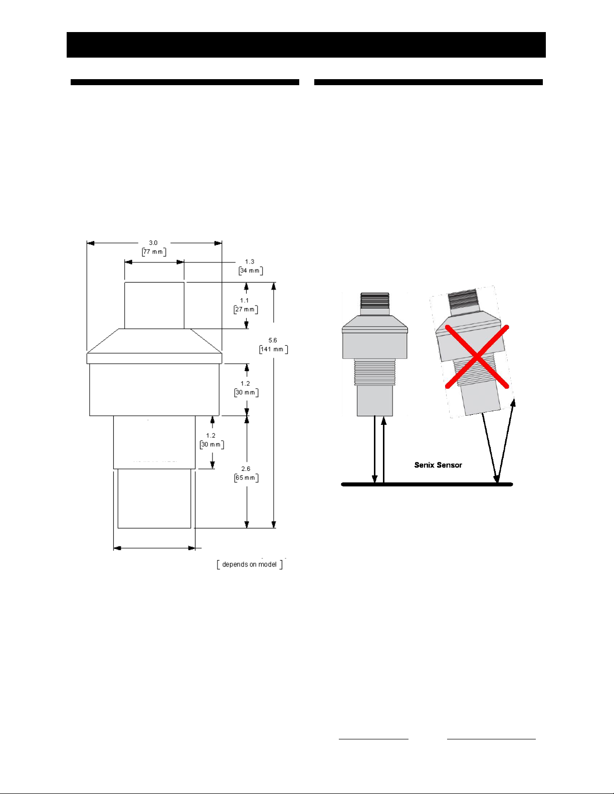
Mechanical Details
Dimensions are inches [mm]. Sensor measurements are
the distance between the ultrasonic transducer face (the
bottom of housing shown below) and the target
material. The lower threads vary by model:
1.5-in Parallel: LVL-100 and LVL-300
2.0-in Parallel: LVL-500
Installation
Precautions
Keep unintended targets from the transducer’s field
of view. Keep the beam pattern in mind.
Keep the transducer away from ultrasonic noise
sources, such as pressurized air nozzles.
Do not allow material to build up on the sensor face
or sensor performance may suffer.
Orientation
Orient the sensor perpendicular to the liquid surface or
target object for best results as shown in Figure 3.
Figure 3 - Sensor Orientation
Ultrasound energy must reflect back to the sensor or the
sensor will not detect the target, and may detect a later
multipath echo (which would “measure” as a lower tank
level).
Location and Obstacles
Figure 2 – Housing Dimensions
Senix Corporation, 10516 Route 116 Suite 300, Hinesburg, VT 05461 USA
802.489.7300 or 800.677.3649, FAX: 802.489.7400, Web: www.senix.com, e-mail: support@senix.com
Page 9 of 38 – May 31, 2015
The sensor mounting location should be chosen so there
are no obstacles in the beam path that reflect the
ultrasound beam back to the sensor.

ToughSonic® LVL Family Sensors - Installation & Operating Instructions
ToughSonic ® CHEM Family Sensors – Installation & Operating Instructions
Configuration and Communication
SenixVIEW Software
Configure, test and clone sensors.
Compatible with all TSPC models.
Download free from:
www.senix.com/download-3.htm
UA-KIT-232
UA-KIT-485
PC Interface kits. Choose RS232
or RS-485 according to sensor
model. Cable w/ terminal block,
power supply and CD included.
UA-USB-232-ISO
Use with UA-KIT-232 to connect to
a USB port at the PC
UA-USB-485-ISO
Use with UA-KIT-485 to connect to
a USB port at the PC
UA-TS-TB
Termination Board, connects
sensor, equipment, and power &
PC cable. DIN rail mountable.
UA-TS-TB-2RYC
Relay Board, similar to UA-TS-TB
but adds 2 relays (driven by
sensor switch outputs).
BEST ACCEPTABLE AVOID
Figure 5 - Nipple Mounting
Maintenance & Cleaning
Dust accumulation on the sensor face can be cleaned by
The sensor can be mounted close to a vertical pipe or
tank wall if the wall or pipe surfaces are smooth (see
“Acceptable” above).
Make sure that unintended targets between the sensor
and liquid surface are not in the sensor’s beam area.
Keep the sensor away from horizontal pipes, inflow
points, vertical pipe seams, or tank seams if they are
large enough to reflect the ultrasound. The sensor
measures to the closest target and will detect submerged
equipment if the level drops below the equipment.
Position the sensor to avoid these issues (see “Avoid”
illustration above).
blowing pressurized air across the sensor face. In
general, dust does not affect performance unless it
totally blocks the sound path. The sensor face can be
cleaned with alcohol or any cleaner compatible with
Kynar (PVDF).
Accessories
The following accessories are available.
Mounting
Figure 4 – Flange Mounting
Typical tank installations have the sensor threaded into
a flange as shown above, or threaded into a nipple
welded to the top of the tank. A plastic nipple or flange
adapter is preferred. A nipple is shown in Figure 5. In
both cases the mounting should ensure that the sensor is
facing perpendicular to the liquid surface. Use no
wrenches when screwing the sensor into the nipple or
flange.
Senix Corporation, 10516 Route 116 Suite 300, Hinesburg, VT 05461 USA
802.489.7300 or 800.677.3649, FAX: 802.489.7400, Web: www.senix.com, e-mail: support@senix.com
Page 10 of 38 – May 31, 2015
ToughSonic® LVL Family Sensors - Installation & Operating Instructions
ToughSonic ® CHEM Family Sensors – Installation & Operating Instructions
Wire
Color
Wire Function
Brown
+DC input voltage (Power Input)
Blue
-DC input and signal common (Ground)
Black
Sinking Switch #1 (note 2)
OR
Sourcing Switch #1 (page 14)
White
Sinking Switch #2 (note 2)
OR
Sourcing Switch #2 (page 14)
Green
4-20 mA sourcing loop (page 12)
Orange
4-20 mA sinking loop (page12)
Violet
0-10 VDC (page 12)
Gray
(data #1)
(note 1)
LVL-xxxx-232: RS-232 out
LVL-xxxx-485: RS-485 -
Yellow
(data #2)
(note 1)
LVL-xxxx-232: RS-232 in
LVL-xxxx-485: RS-485 +
Silver
Cable shield (bare stranded wire)
Notes:
(1) The gray and yellow wire functions depend on sensor
model, and can be used for synchronization (page20)
(2) Factory default selections (can be changed using
SenixVIEW)
Sensor
User Equipment
(RS-232 interface)
Single point ground
optional (recommended)
DC+
(Brown)
Blue
Cable Shield
RX
GND
DB9* DB25*
+
Power Supply
(24 VDC typical)
-
2
5
* Typical personal computer connections for
9 and 25-pin serial COM connectors
Yellow
RS-232
Wiring
Gray
TX
3
3
7
2
Power Input (brown wire)
Connect a DC power supply to the DC+ (Brown) and
INTERFACES
GND (Blue) wires. These colors conform to EU
standards. Reversing the power connections will not
damage the sensor. A power supply voltage between
15-30 VDC is recommended. A +24 VDC supply is a
commonly used standard. Target sensitivity and the
Wiring
CHEM sensors have a potted-in 9-wire shielded cable
with the following wire assignments:
maximum voltage output value is reduced at power
supply voltages below 15 VDC. When power is applied
the sensor operates as described on page 20.
Data Connections (gray & yellow)
Serial data interfaces are described on page 17. They
are used for:
SenixVIEW PC configuration (page 30 )
Synchronization (page 20)
User communications between the sensor and an
external data communications device
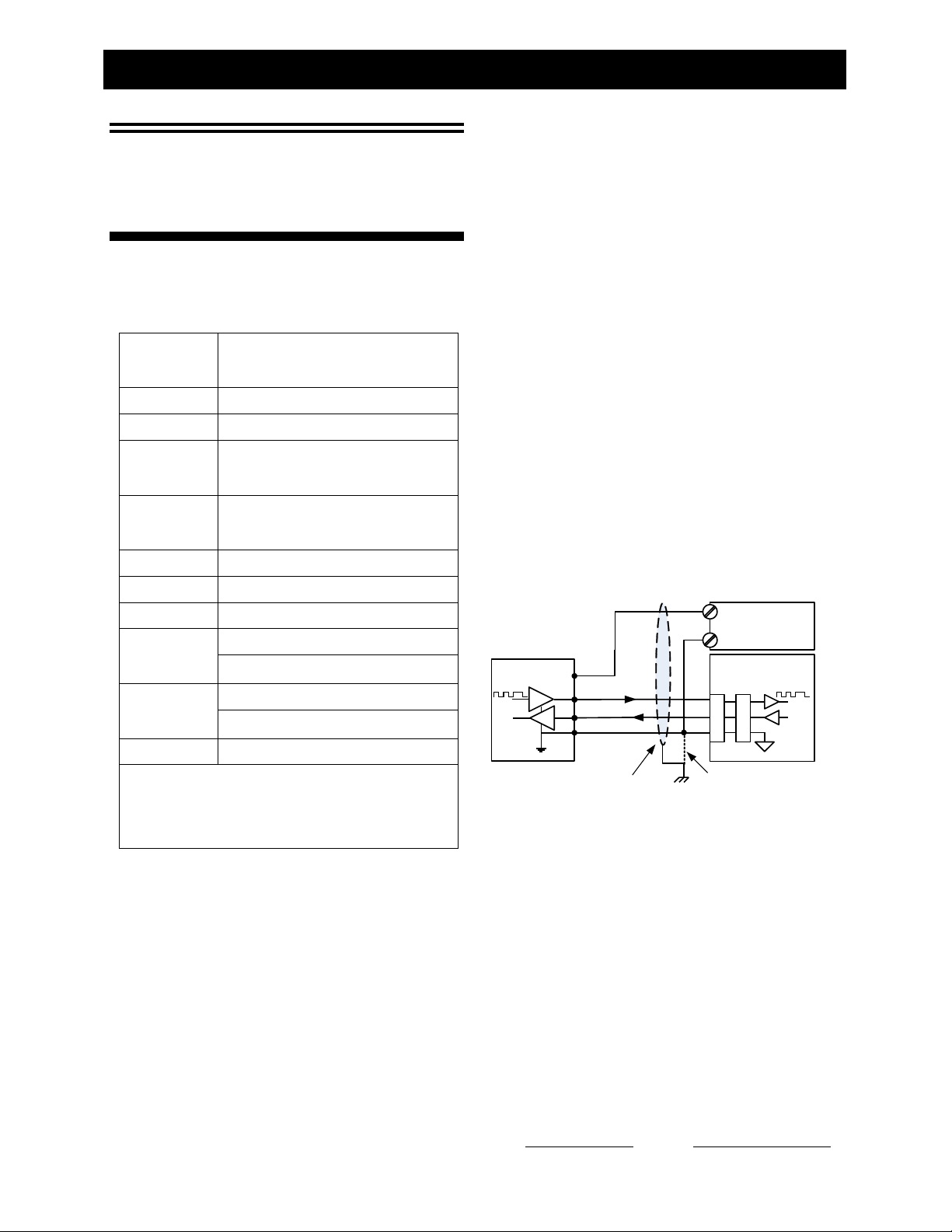
LVL-xxxx-232 models require an RS-232 interface and
connect directly to a PC COM (serial) port for
SenixVIEW configuration as shown below.
Table 2 - Wire Assignments
Ground (blue wire)
The ground wire is common to both the power supply
and the output circuits.
Figure 6 - RS-232 PC COM Port Connections
RS-485 is not compatible with a standard PC serial port
(DB9 plug), which is RS232. LVL-xxx-485 models
require a RS-485 interface, like Senix’s UA-KIT-485
interface kit, plus the UA-USB-485-ISO adaptor for a
Cable Shield (bare wire)
The cable shield is not terminated at the sensor. This
wire should be terminated to equipment ground near the
user equipment, preferably to a single point ground for
all equipment. This is important if the cable is
lengthened and/or routed near electrically noisy wiring
or equipment.
802.489.7300 or 800.677.3649, FAX: 802.489.7400, Web: www.senix.com, e-mail: support@senix.com
Senix Corporation, 10516 Route 116 Suite 300, Hinesburg, VT 05461 USA
Page 11 of 38 – May 31, 2015
USB port connection. See Accessories on page 10.

ToughSonic® LVL Family Sensors - Installation & Operating Instructions
ToughSonic ® CHEM Family Sensors – Installation & Operating Instructions
GND
+
0-10 VDC
(Violet)
Sensor
User Equipment
(Voltage Input)
+
Power Supply
(24 VDC typical)
-
Single point ground
optional (recommended)
DC+
(Brown)
GND
(Blue)
Cable Shield
-
DC
Do not ground!
Differential input
recommended
+
4-20 ma.
(ORG)
Sensor
User Equipment
(Current Loop Input)
+
Power Supply
(24 VDC typical)
-
Single point ground
optional (recommended)
DC+
(BRN)
GND
(BLU)
Cable Shield
Direction of
current flow
Maximum loop
resistance 1K @ 24
VDC loop voltage
-
may be GND if
single ended
+
4 - 20
mA
Sensor
User Equipment
(
Current Loop Input
)
+
Power Supply
(
24
VDC typical
) - Single point ground
optional
(
recommended
)
DC
+
(
Brown
)
GND ( Blue
)
Cable Shield
Direction of
current flow
Maximum loop
resistance
450
Ω
@
24
VDC sensor
input voltage
-
GREEN wire
is recommended). In a sourcing loop current flows out
Analog Outputs
of the sensor, through the user equipment and back via
the sensor’s ground (BLUE wire).
CHEM sensors have three analog outputs - voltage,
sourcing current loop and sinking current loop. They all
Sinking Current Loop (orange wire)
share the same endpoints and slope (decreasing or
increasing with distance). They are simultaneously
available on separate wires.
Voltage Output (violet wire)
This figure shows a voltage output connection:
Figure 9 - Sinking Current Loop Wiring
The default sinking loop output is a 4 to 20 mA signal
proportional to the measured distance between two
Figure 7 - Voltage Output Wiring
The default voltage output is a 0 to 10 volt DC signal
proportional to the measured distance between the
endpoints set by the user. The current low/high values
are SenixVIEW adjustable and match those of the
sourcing loop. Current flows from the power supply
through the user equipment then INTO the sensor
(ORG wire) as shown in Figure 9.
endpoints set by the user. The voltage range limits are
adjustable to values between 0 and 10 volts using
SenixVIEW (see d & e in Figure 10 ). The voltage is
measured relative to GND (BLUE wire). The 0 and 10
volt endpoint distances affect all voltage and current
loop outputs, and can be set anywhere in the sensor’s
operating range using SenixVIEW.
The analog inputs of User Equipment in Figure 9 are
either differential (both + and – terminals) or single
ended (+ and GND terminals). A differential input is
recommended at the user equipment. If the user
equipment is single ended (+ input and GND) the
sensor and user equipment cannot share a common
ground or the current loop will not work.
Sourcing Current Loop (green wire)
This figure shows a sourcing current loop connection:
Endpoints and Slope
The voltage and current loop(s) are spanned between
the same two endpoint distances (see b & c in Figure
10). Endpoints can be set anywhere in the sensor’s
operating range using SenixVIEW.
All analog outputs must have the same slope, i.e.,
increase or decrease in value in proportion to distance.
The high and low output values (voltages and currents),
however, are independently adjustable in SenixVIEW
for the voltage and current loops.
Response Time
Analog response time is affected by measurement rate
Figure 8 - Sourcing Current Loop Wiring
The default sourcing loop output is a 4 to 20 mA signal
proportional to the measured distance between two
endpoints set by the user. The current low/high values
are adjustable to any values between 0 and 20 mA using
SenixVIEW (see d & e in Figure 10) (4 mA minimum
Senix Corporation, 10516 Route 116 Suite 300, Hinesburg, VT 05461 USA
802.489.7300 or 800.677.3649, FAX: 802.489.7400, Web: www.senix.com, e-mail: support@senix.com
Page 12 of 38 – May 31, 2015
and filter selections (pg.24).
Analog Displays in SenixVIEW
The sensor’s calculated analog output values are shown
in real time on the SenixVIEW meter displays (page
22).
 Loading...