

INSTRUCTION MANUAL CODE 80049 REV H 15/07/03(It can be modified without notice) Page: 1
ISO 9001
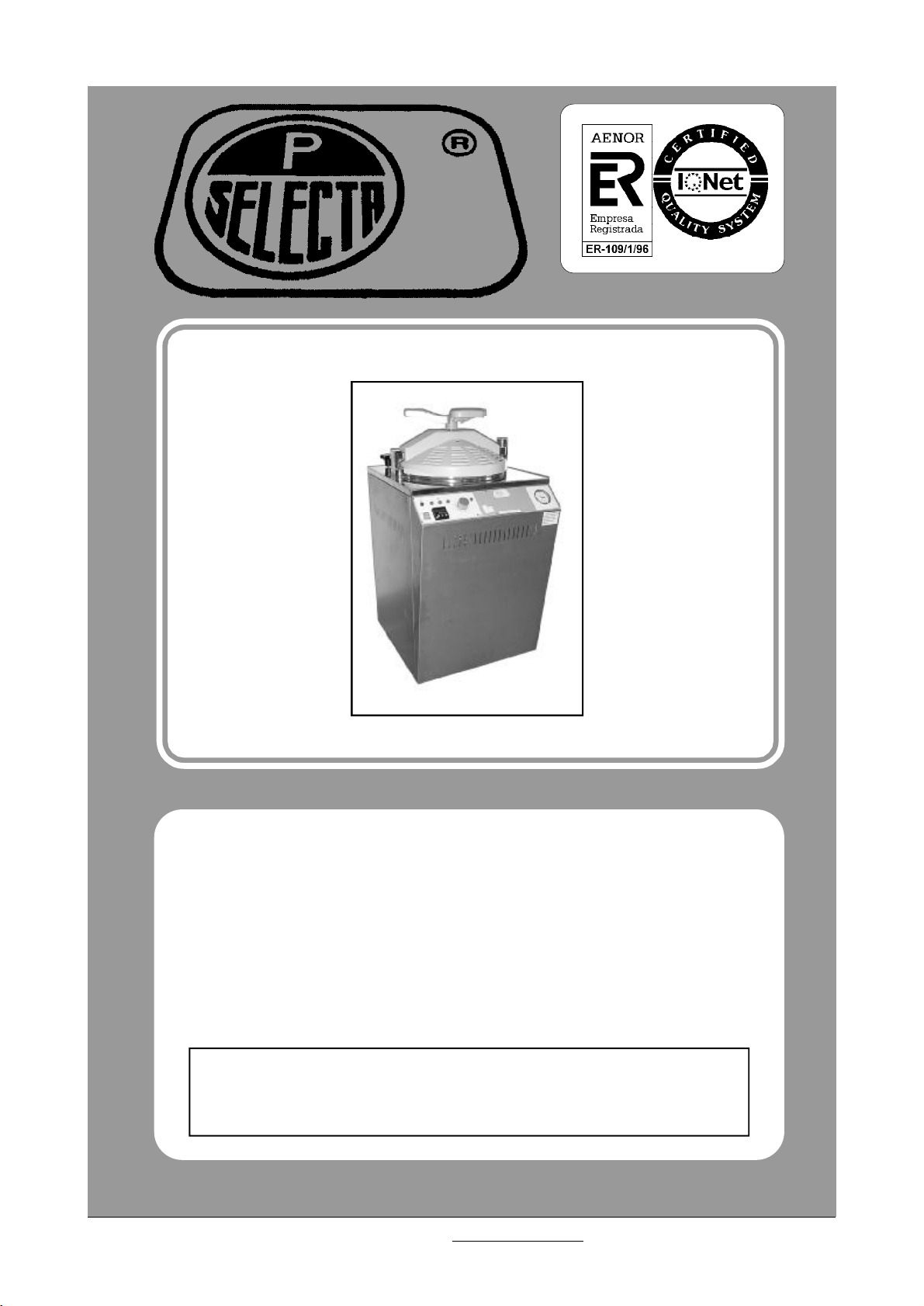
PRESOCLAVE 30 L4001135
PRESOCLAVE 75 L4001136
AUTOCLAVES ELÉCTRICOS PARA ESTERILIZACIÓN A VAPOR
ELECTRIC AUTOCLAVE FOR STERILIZATION
CON ENVOLVENTE DE PROTECCIÓN TÉRMICA EN LA TAPA SEGÚN
DIRECTIVA DE LA CEE NORMA «UNE-EN 61010-1».
WITH THERMAL PROTECTIVE WRAPPING ONTO THE LID ACCORDING
TO «EN 61010-1» STANDARD.
J.P. SELECTA s.a.Ctra. NII Km 585.1 Abrera 08630 (Barcelona) EspañaTel (34 3) 770 08 77 Fax (34 3) 770 23 62
e-mail: jpselecta @ sefes.es - http://www.sefes.es/selecta

MANUAL DE INSTRUCCIONES CODIGO 80049 REV H 15/07/03(Sujetas a modificaciones sin previo aviso)Pag.: 2
INFORMACIÓN GENERAL
1)Manipular el paquete con cuidado. Desembalarlo y
comprobar que el contenido coincide con lo indicado
en el apartado de la “Lista de embalaje”. Si se observa algún componente dañado o la ausencia de alguno avisar rápidamente al distribuidor.
2)No instalar ni utilizar el equipo sin leer, previamente,
este manual de instrucciones.
3)Estas instrucciones forman parte inseparable del aparato y deben estar disponibles a todos los usuarios
del equipo.
4)Cualquier duda puede ser aclarada contactando con
el servicio técnico de J.P. SELECTA, s.a.
5) ¡ATENCIÓN! NO SE ADMITIRÁ NINGUNA MÁQUI-
NA PARA REPARAR QUE NO ESTÉ DEBIDAMENTE LIMPIA Y DESINFECTADA.
6)Toda modificación, eliminación o falta de mantenimiento de cualquier dispositivo de la máquina,
transgrede la directiva de utilización 89/655/CEE y el
fabricante no se hace responsable de los daños que
pudieran derivarse.
GENERAL INFORMATION
1)Handle the parcel with care. Unpack and check
that the contents coincide with the packing-list. If
any part is damaged or missing, please advise
the distributor immediately.
2)Do not install or use the equipment without reading this handbook before.
3)This handbook must always be attached to the
equipment and it must be available for all users.
4)If you have any doubts or enquiries, please contact with your supplier or J.P. Selecta’s technical
service.
5) IMPORTANT! J.P. SELECTA WILL NOT AC-
CEPT ANY APPARATUS TO BE REPAIRED IF
IT IS NOT DULY CLEANED.
6)If any modification, elimination or lacking in maintenance of any device of the equipment by the
user transgress the directive 89/655/CEE , the
manufacturer is not responsible for the damage
that can occur.
7)No utilizar el equipo con fluidos que puedan desprender vapores o formar mezclas explosivas o inflamables.
7)Do not use the apparatus with liquids which can
give off vapours capable of making explosive mixtures.
ÍNDICE CONTENTS PÁG. / PAGE
INFORMACIÓN GENERAL GENERAL INFORMATION 2
ÍNDICE CONTENTS 2
LISTA DE EMBALAJE PACKING LISTS 3
ACCESORIOS ACCESSORIES 3
ESPECIFICACIÓN TÉCNICA TECHNICAL FEATURES 3
DESCRIPCIÓN DEL EQUIPO EQUIPMENT DESCRIPTION 4
INSTALACIÓN INSTALLATION 5
OPERACIÓN OPERATION 6
GARANTÍA GUARANTEE 19
ESQUEMA ELÉCTRICO ELECTRICAL DIAGRAM 20
RECAMBIOS SPARE PARTS 21
MANTENIMIENTO MAINTENANCE 21
J.P. SELECTA s.a.Ctra. NII Km 585.1 Abrera 08630 (Barcelona) EspañaTel (34 3) 770 08 77 Fax (34 3) 770 23 62
e-mail: jpselecta @ sefes.es - http://www.sefes.es/selecta

INSTRUCTION MANUAL CODE 80049 REV H 15/07/03(It can be modified without notice) Page: 3
LISTA DE EMBALAJE
El equipo estándar consta de los siguientes componentes:
Descripción / DescriptionCódigo / Code
PRESOCLAVE
Cubre-resistencia / Heater protector
Portagomas / Carry Rubbers
Alargo / Extend
Manual de instrucciones / Instruction manual
ACCESORIOS
( Los accesorios deben ser instalados en fábrica)
* Dispositivo de seguridad que impide la apertura de la
tapa mientras la cámara se encuentra bajo presión.
Código 4001137 (este accesorio debe instalarse en
fábrica).
PACKING LIST
The standard equipment consist of the following
components:
40011354001136
56015600
34100
80049
ACCESSORIES
( They must be installed in the factory )
*Safety device that prevents door being opened while
the chamber is pressured. Code 4001137 (It must be
fitted in the factory).
* Sonda de Pt100 para lectura de la temperatura inte-
rior del depósito, con terminal para se rconectado a
un registrador ó termómetro con entrada de Pt100.
Código 4001219
*Cestillos en plancha perforada en acero AISI 316:
Código cestillo
Basket code
1000495 282040011352
1000496 382840011362
Medidas (cm)
Dimensions (cm)
ØAltura / Depth
ESPECIFICACIÓN TÉCNICA
Tensión de alimentación 115-230V 50/60 Hz según se
indique en la placa de características de la máquina.
Medidas
útiles (cm)
Chamber
dimensions
(cm)
Ø
Alto
Depth
Overall dimensions
Alto
Height
Código
Code
Capacidad
litros
Capacity
litres
* Temperature probe Pt100 for reading the internal
temperature of the chamber. A terminal permits the
Pt100 to be connected to a printer or temperature
measuring device. Code 4001219.
*Baskets in perforated plate of AISI 316 stainless steel:
Código Autoclave /
Autoclave code
Capacidad cestillos/
No of baskets
TECHNICAL FEATURES
Voltage supply 115-230 V 50/60 Hz as indicated on
the characteristics plate.
Medidas
exteiores (cm)
(cm)
Ancho
Length
Fondo
Width
Rango
ºC
Range
ºC
Consumo
(W)
Consump.
(W)
Peso
(Kg)
Weight
(Kg)
4001135 303040904856
4001136 7540601055766340085
J.P. SELECTA s.a.Ctra. NII Km 585.1 Abrera 08630 (Barcelona) EspañaTel (34 3) 770 08 77 Fax (34 3) 770 23 62
e-mail: jpselecta @ sefes.es - http://www.sefes.es/selecta
115/
134
210055

MANUAL DE INSTRUCCIONES CODIGO 80049 REV H 15/07/03(Sujetas a modificaciones sin previo aviso)Pag.: 4
DESCRIPCIÓN DEL EQUIPO
Los PRESOCLAVE son una serie de autoclaves semiautomáticos con regulación y lectura digital.
EQUIPAMIENTO:
* Triple sistema de seguridad:
Valvula de seguridad:
Previene que la presión sobrepase el límite máximo.
Presostato de seguridad:
Desconecta los calefactores en caso de sobrepasar el
límite de presión.
Termostato de seguridad:
EQUIPMENT DESCRIPTION
PRESOCLAVE are autoclaves with semi-automatic
control and digital temperature reading.
EQUIPMENT:
* Triple safety system:
Safety pressure switch:
Prevents the pressure surpassing the set maximum
limit.
Safety valve:
Disconects the heating element in the event of over
pressure surpassing the set maximum limit.
Safety thermostat:
Desconecta la calefacción por sobretemperatura o falta
de agua en el depósito.
Envolvente de protección térmica de la tapa.
* Caldera, brazo y tapa en acero inoxidable 18/8/2.
* Mueble exterior en acero inoxidable.
* Válvula manual de desvaporización.
* Manovacuómetro hasta 3kg/cm²
PRESTACIONES:
Temperatura de esterilización desde 115°C hasta 134°C.
Tiempo de esterilización desde 1 min. hasta 60 min.
Disconnects power to the heating element in the event
of over temperature or the lack of water in the reservoir.
Thermal protection:
* Chamber, lid and lock system in AISI 316 stainless
steel.
* Top and outer casing in AISI 304 stainless steel.
* Automatic air exhaust at start of sterilization cycle.
* Pressure and vacuum gauge up to 3kg/cm²
FEATURES:
Sterilization temperature from 115°C up to 134°C.
Sterilization time from 1 minute up to 60 minutes.
J.P. SELECTA s.a.Ctra. NII Km 585.1 Abrera 08630 (Barcelona) EspañaTel (34 3) 770 08 77 Fax (34 3) 770 23 62
e-mail: jpselecta @ sefes.es - http://www.sefes.es/selecta

INSTRUCTION MANUAL CODE 80049 REV H 15/07/03(It can be modified without notice) Page: 5
INSTALACIÓN
Situar el autoclave cerca de una toma de corriente adecuada al consumo de la máquina.
Inmovilice el autoclave ajustándolo al suelo, mediante
los topes situados en la parte anterior del aparato,
previstos para tal efecto.
Utilizar siempre agua descalcificada.
Fijar una manguera en la tetina de salida de agua/
vapor de la máquina, y fijar también el otro extremo a
un recipiente o desagüe procurando NO OBSTRUIR
EL PASO.
¡ATENCIÓN! IMPORTANTE PARA SU SEGURIDAD
CAUTION!!! IMPORTANT FOR YOUR SAFETY
INSTALLATION
Place the autoclave near a suitable electric mains.
Immobilise the autoclave with the stops provided in
the front part of the apparatus.
Always use decalcified water.
Fix a hose in the water/steam exit nipple of the machine,
and also fix the other end to a drain or deposit without
OBSTRUCTING THE FLOW.
¡ATENCIÓN! El escape del vapor es a PRESIÓN y a
TEMPERATURA ELEVADA. Tome todas las precau-
ciones para evitar GRAVES QUEMADURAS.
NUNCA SUJETE DICHA MANGUERA CON LA MANO
YA QUE PODRIA OCASIONAR QUEMADURAS.
No instalar el autoclave en zonas donde se almacenen
líquidos inflamables o zonas con protección especial.
No utilice el equipo sin estar conectada la toma
de tierra.
Antes de abrir la tapa del autoclave comprobar SIEMPRE que NO haya PRESIÓN. El indicador del
manómetro instalado en el panel de mandos debe marcar 0kg/cm².
Asegúrese que el equipo se conecta a una tensión de red que coincide con la indicada en la
placa de características.
Si cambia la clavija de enchufe tenga en cuenta
lo siguiente:
ATTENTION!!! The PRESSURE and HIGH
TEMPERATURE of the steam exit require the
necessary precautions to avoid SERIOUS BURNS.
NEVER PRESS THIS HOSE BY HAND.
Do not install the autoclave in places where inflammable
liquids are stored or in zones with special protection.
Do not use the autoclave if it is not earthed.
Before opening the cover ALWAYS check that there
is NOT PRESSURE. The pressure gauge indicator
installed in the control panel must read 0kg/cm².
Be sure that the voltage supply is the same as the
one indicated on the characteristics plate.
If you change the plug bear in mind the following:
Cable azul:Neutro.
Cable marrón: Fase.
Cable amarillo/verde: Tierra.
J.P. SELECTA s.a.Ctra. NII Km 585.1 Abrera 08630 (Barcelona) EspañaTel (34 3) 770 08 77 Fax (34 3) 770 23 62
e-mail: jpselecta @ sefes.es - http://www.sefes.es/selecta
Blue cable: Neutral.
Brown cable: Phase.
Yellow/green cable: Earth.

MANUAL DE INSTRUCCIONES CODIGO 80049 REV H 15/07/03(Sujetas a modificaciones sin previo aviso)Pag.: 6
OPERACIÓN
PANEL DE MANDOS:
1
1.Interruptor general.
2.Reloj temporizador de 0-56’.
3.Manómetro.
4.Regulador de temperatura.
5.Indicador luminoso de final de ciclo esterilizado.
6.Indicador de fase de esterilización.
7.Indicador luminoso de alarma.
8.Indicador calefacción.
9.Indicador puerta mal cerrada.
4
2
OPERATION
CONTROL PANEL:
37 8 9 5 6
1.Main switch.
2.Timer 0-56’.
3.Pressure gauge.
4.Temperature Controller.
5.Indicator lamp for sterilised cycle end.
6.Indicator lamp sterilisation phase.
7.Alarm indicator lamp.
8.Heat indicator lamp.
9.Wrong close door indicator lamp.
PARTE POSTERIOR:
23.Válvula de vaciado de vapor.
24.Válvula de seguridad.
26.Termostato de seguridad.
27.Toma de corriente.
28.Válvula de desagüe.
23
24
26
27
REAR PART:
23.Steam drainage valve.
24.Safety valve.
26.Safety thermostat.
27.Power point.
28.Drainage valve.
VACIADO
28
DRAINAGE
VAPOR
STEAM
23
J.P. SELECTA s.a.Ctra. NII Km 585.1 Abrera 08630 (Barcelona) EspañaTel (34 3) 770 08 77 Fax (34 3) 770 23 62
e-mail: jpselecta @ sefes.es - http://www.sefes.es/selecta
INSTRUCTION MANUAL CODE 80049 REV H 15/07/03(It can be modified without notice) Page: 7
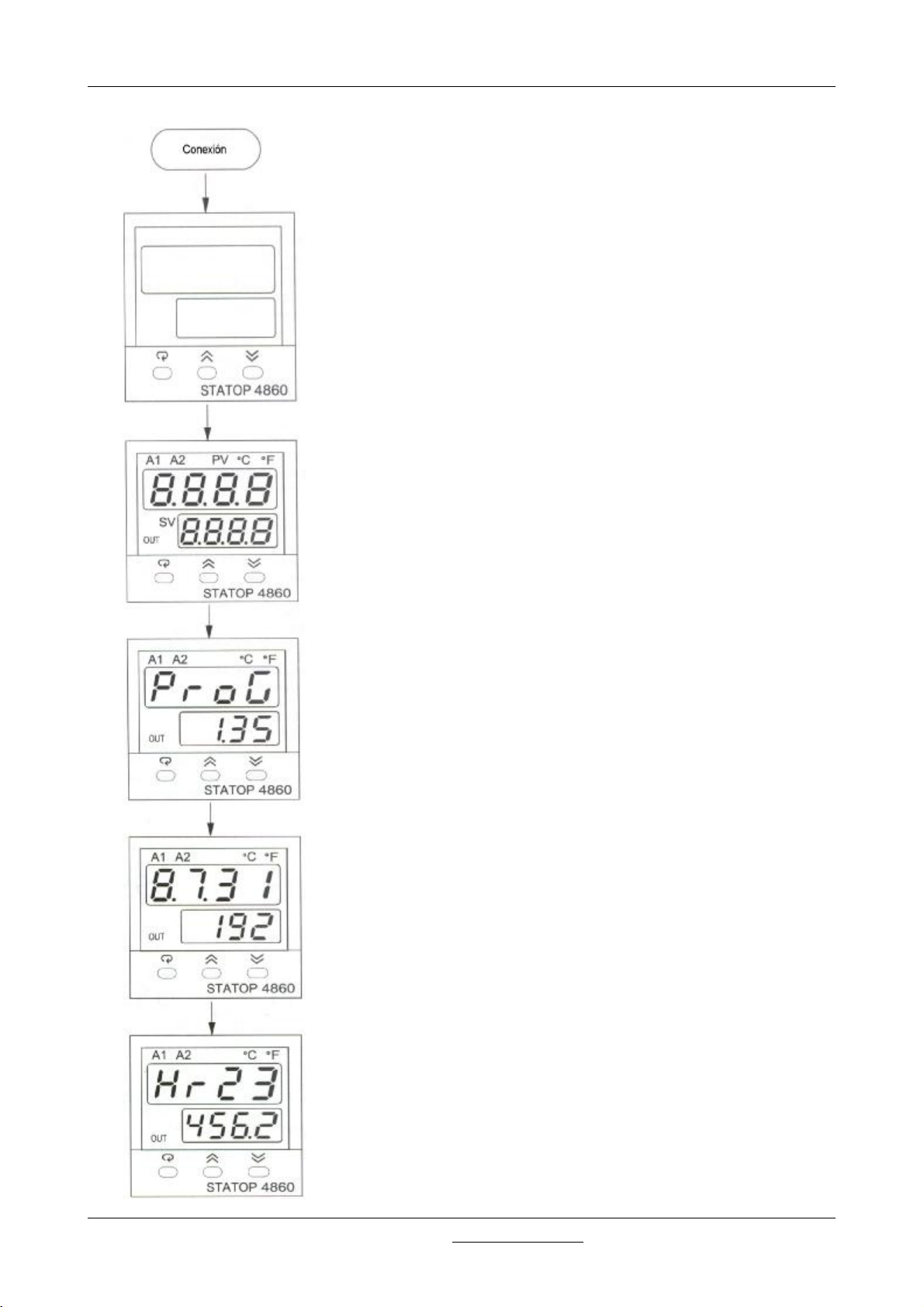
FUNCIONAMIENTO DEL REGULADOR DE TEMPERATURA STATOP 4860
STATOP 4860 TEMPERATURE CONTROLLER OPERATION
Ningua lectura durante 0,5 segundos.
No display during 0.5 seconds.
Todos los indicadores y luminosos se iluminan durante 2
segundos.
All the displays and LEDS are illuminated for a 2 seconds.
Muestra la versión de software del instrumento durante 2,5
segundos.
Display of the product software verion for 2.5 seconds.
Muestra la fecha de fabricación del instrumento durante 2,5
segundos.
Display of the product fabrication date for 2.5 seconds.
Muestra el tiempo de funcionamiento en horas durante 2,5
segundos.
En el ejemplo 23.456,2 horas desde su fabricación.
Display of product use time in hours for 2.5 seconds.
The display indicates that the unit has been used for
23456.2 hours since its fabrication.
J.P. SELECTA s.a.Ctra. NII Km 585.1 Abrera 08630 (Barcelona) EspañaTel (34 3) 770 08 77 Fax (34 3) 770 23 62
e-mail: jpselecta @ sefes.es - http://www.sefes.es/selecta

MANUAL DE INSTRUCCIONES CODIGO 80049 REV H 15/07/03(Sujetas a modificaciones sin previo aviso)Pag.: 8
Tecla / Keys Función / Function Descripción / Description
Pulsar y soltar rápidamente para aumentar el valor del
parámetro. Mantener pulsado para aumentar la
Tecla de aumento
velocidad de aumento
Pulsar / Press
durante 3 segundos / for 3 seconds
Pulsar / Press
durante 6 segundos / for 6 seconds
Pulsar / Press
Up arrow
Tecla de disminución
Down arrow
Tecla de programación
Scroll key
Entrada a nivel usuario
Entry key
Guardar datos
Save key
Retroceder
Reverse scrolling key
Press and release rapidly to increase the parameter
value.
Press and maintain to inrease the increment speed.
Pulsar y soltar rápidamente para disminuir el valor del
parámetro. Mantener pulsado para aumentar la
velocidad de disminución.
Press and release rapidly to decrease the parameter
value.
Press and maintain to derease the increment speed.
Seleccionar el parámetro.
Select the parameter.
Para acceder a otros parámetros del nivel de usuario,
también para acceder al modo manual, modo de
regulación por defecto y para guardar los datos de
calibración durante el proceso de calibrado.
To acces more parameters in the User menu; it is also
used for manual mode, default control mode and to
save calibration data during the calibration procedure.
Puesta a cero de los valores históricos máximos
guardados en PVHI y PVLO e iniciar a registrar de
nuevos.
Set the archived parameters of PVHI and PVLO to zero
and start saving the peak values maesured.
Selección del parámetro anterior del menú.
Select a parameter by scrolling up the menu.
Pulsar / Press
Pulsar / Press
Pulsar / Press
durante 3 segundos / for 3 seconds
Pulsar / Press
simultáneamente / Together
Selección modo
Mode key
Puesta a cero
Reset key
Función sleep (SLEP)
Sleep key
Función fábrica
Factory key
Selección del modo operativo.
Select the operating mode.
Volver a la indicación normal, también para finalizar la
autoadaptación y salir del modo manual o del SLEP.
Return to normal display. Also used to end selfadaptation ad manual control, as well as to quit the
sleep mode.
El regulador pasa a la función SLEP si la mima fue
activada (seleccionar YES).
The controller switches to sleep mode if the sleep
function (SLEP) is activated (select YES).
El código correcto permite la ejecución de los
programas de diagnosis. Esta función se utiliza en
fábrica para generar los informes de diagnosis. El
usuario no deberá jamás tratar de activar esta función.
The correct safety code permits running
troubleshooting programs. This function is used in the
factory to manage troubleshooting reports. You must
never try to activate this function.
J.P. SELECTA s.a.Ctra. NII Km 585.1 Abrera 08630 (Barcelona) EspañaTel (34 3) 770 08 77 Fax (34 3) 770 23 62
e-mail: jpselecta @ sefes.es - http://www.sefes.es/selecta

INSTRUCTION MANUAL CODE 80049 REV H 15/07/03(It can be modified without notice) Page: 9
Adjustment point
indicator
Output 1
Indicator
Alarm 1 Indicator
Alarm 2 / Output 2 indicator
Process value indicator
Unit indicator
Upper display
To display the value, the menu
symbol, error code, etc.
Lower display
To display the set point value,
parameter value or the control
output value, etc.
3 silicon rubbers buttons
to facilitate and adjust
adjustment values
J.P. SELECTA s.a.Ctra. NII Km 585.1 Abrera 08630 (Barcelona) EspañaTel (34 3) 770 08 77 Fax (34 3) 770 23 62
e-mail: jpselecta @ sefes.es - http://www.sefes.es/selecta

MANUAL DE INSTRUCCIONES CODIGO 80049 REV H 15/07/03(Sujetas a modificaciones sin previo aviso)Pag.: 10
PV value
SV value
SHIF
PB1
FUNC
COMM
IN1
IN1U
DP1
IN2
OUT1
O1TY
CYC1
O1FT
OUT2
A1FN
A2FN
EIFN
PVMD
FILT
SELF
SLEP
SPMD
SP1L
SP1H
SEL1
SEL2
SEL3
SEL4
SEL5
TI1
TD1
PL1
J.P. SELECTA s.a.Ctra. NII Km 585.1 Abrera 08630 (Barcelona) EspañaTel (34 3) 770 08 77 Fax (34 3) 770 23 62
e-mail: jpselecta @ sefes.es - http://www.sefes.es/selecta

INSTRUCTION MANUAL CODE 80049 REV H 15/07/03(It can be modified without notice) Page: 11
Situación
Place
Símbolo
Symbol
Formato
lectura
Display
format
Descripción
Description
Rango ajuste
4,3 (30L.)
Range
Valor por
defecto
Default
value
Decalado lectura
SHIF SHiF
(offset) PV1
-200,0 ......+200,0ºC-1,0
PV1 display offset
Menú
usuario
User
Menu
PB1 Pb I
TI1 ti I
TD1 td I
PL1 PL I
A2SP A2.SP
A2HY A2.HY
Banda proporcional 1
Proportional band 1
Tiempo integral 1
Value of integral 1
Tiempo derivada 1
Value of derivative 1
Limitación salida 1
Power limitation output 1
Consigna alarma 2
Alarm 2 setpoint
Hysteresis alarma 2
Hysteresis of alarma 2
0....500,0ºC3,1
0....1000 segundos / seconds 127
0....360,0 segundos / seconds 38,1
0....100%100
Ver tablas 7.1 y 7.4
See tables 7.1 y 7.4
0,1....10,0ºC0,4
4,3 (30L.)
3,3 (75L.)
128 (30L.)
148 (75L.)
38,4 (30L.)
44,4 (75L.)
104
Menú
ajuste
Adjustem-
ent
Menu
FUNC FunC
COMM Coññ
IN1 i n I
Acceso al nivel de las
funciones
Acces to the
complexity of the
functions
Tipo de interface de
comunicación
Type of
Communication
interface
Señal de entrada 1
Selection of sensor
type for input IN1
0 bASC: Modo funciones de base
Basic functions mode
1 FuLL: Modo funciones superior
Advanced functions mode
0 nonE: Sin comunicación
no communication function
1 485 : Interface RS485
2 232 : Interface RS232
3 4-20 : 7...20 mA
retransmisión analógica de corriente
retransmission of analogue current
4 0-20 : 0...20 mA
retransmisión analógica de corriente
retransmission of analogue current
5 0-1u : 0...1 V
retransmisión analógica de tensión
retransmission of analogue voltage
6 0-5u : 0...5 V
retransmisión analógica de tensión
retransmission of analogue voltage
7 1-5u : 1...5 V
retransmisión analógica de tensión
retransmission of analogue voltage
8 0-10 : 0...10 V
retransmisión analógica de tensión
retransmission of analogue voltage
0 J_tC : termopar tipo J type thermocouple
1 K_tC : termopar tipo K type thermocouple
2 T_tC : termopar tipo T type thermocouple
3 E_tC : termopar tipo E type thermocouple
4 B_tC : termopar tipo B type thermocouple
5 R_tC : termopar tipo R type thermocouple
6 S_tC : termopar tipo S type thermocouple
7 n_tC : termopar tipo N type thermocouple
8 L_tC : termopar tipo L
9 Pt.dn : Pt100 DIN
10 Pt.JS : Pt100 JIS
11 4-20: corriente 4...20 linear
12 0-20: corriente 0...20 mA linear
13 0-1u : tensión 0...1 V linear voltage
14 0-5u : tensión 0...5 V linear voltage
15 I -5u : tensión 1...5 V llinear voltage
16 0-10 : tensión 0...10 V linear voltage
17 SPEC: linealización especial
Courbe for specific
bASC
nonE
Pt.dn
J.P. SELECTA s.a.Ctra. NII Km 585.1 Abrera 08630 (Barcelona) EspañaTel (34 3) 770 08 77 Fax (34 3) 770 23 62
e-mail: jpselecta @ sefes.es - http://www.sefes.es/selecta

MANUAL DE INSTRUCCIONES CODIGO 80049 REV H 15/07/03(Sujetas a modificaciones sin previo aviso)Pag.: 12
Situación
Place
Menú
ajuste
Adjustem-
ent Menu
Símbolo
Symbol
lectura
Display
format
IN1U i n I.u
DP1 dP I
IN2 i n 2
OUT 1 out I
O1TY o I.tY
Formato
Descripción
Description
Unidad IN1
Selection of unit IN1
Decimales en IN 1
Selection of point IN1
Señal de entrada 2
Selection of input
type IN2
Sentido regulación
salida 1
Direction of
adjustement Output 1
Tipo de señal en la
salida 1
Signal type for output
1
Rango ajuste
Range
0 ºC : unidad ºC / Unit degree C
1 ºF : unidad ºF / Unit degree F
2 Pu: unidad de proceso / Unit of process
0 no.dP : sin decimales / No point
1 I - dP : 1 decimal / 1 figure after the point
2 2 - dP : 2 decimales / 2 figures after the point
3 3 - dP : 3 decimales / 3 figures after the point
0 nonE: sin uso IN2 / No function IN2
1 Ct : transformador corriente
Current transformer input
2 4 -20 : corriente 4...20 mA
4-20 mA linear current
3 0 -20 : corriente 0...20 mA
0-20 mA linear current
4 0 -1u : tensión 0...1 V
0-1V linear voltage
5 0 -5u : tensión 0...5 V
0-5V linear voltage
6 I -5u : tensión 1...5 V
1-5V linear voltage
7 0 -10 : tensión 0...10 V
0-10V linear voltage
0 rEur : inverso (calefacción)
reverse control action (heating)
1 dirt : directo (refrigeración)
direct control action (cooling)
0 rELY : relé / relay outpu
1 SSrd : binaria para relé estático
solid state relay drive output without DC current
2 SSr : relé estático
solid state relay output
3 4 -20 :corriente 4...20 mA
output current 4-20 mA
Valor por
defecto
Default
Value
ºC
no.dP
nonE
rEur
rELY
Menú
instalación
Installation
Menu
CYC1 CYC I
O1FT o I.Ft
OUT2 out2
Tiempo ciclo salida 1
Cycle time output 1
Valor refugio en caso
de fallo salida 1
Output 1: Safety value
in case of fault
Funciones especiales
para la salida 2
Special Functions for
Output Nº 2
0,1 .... 100,0 segundos / seconds
Seleccionar BPLS entre 0,0 y 100,0%. Después
del fallo, la salida podrá modificarse por las
teclas de aumento o disminución
Select BPLS of 0.0 at 100% to force the power to
a safety value if a fault is detected. After a fault,
the power can be modified directly from the
keyboard by the "up" and "down" arrows.
0 nonE : ninguna / No function
1 CooL : algoritmo calor/frío
Hot / Cold Algorithm
2 =AL2 : alarma / Alarm
3 dCPS : alimentación transmisor señal
Power supply for transmitter
18,0
BPLS
AL2
J.P. SELECTA s.a.Ctra. NII Km 585.1 Abrera 08630 (Barcelona) EspañaTel (34 3) 770 08 77 Fax (34 3) 770 23 62
e-mail: jpselecta @ sefes.es - http://www.sefes.es/selecta

INSTRUCTION MANUAL CODE 80049 REV H 15/07/03(It can be modified without notice) Page: 13
Situación
Place
Menú
instalación
Installation
Menu
Símbolo
Symbol
A1FN AI.Fn
Formato
lectura
Display
format
Descripción
Description
Funciones de la
alarma 1
Functions of Alarm 1
Rango ajuste
Range
0 nonE: sin función / No alarm function
1 ti ñr : temporizador / Timer action
2 dE.Hi : alarma relativa alta
High deviation alarm
3 dE.Lo : alarma relativa baja
Low deviation alarm
4 db.Hi : alarma simétrica alta
High symmetric deviation alarm
5 db.Lo :alarma simétrica baja
Low symmetric deviation alarm
6 PuI.H : alarma absoluta alta sobre
IN1
Alarm on IN1 High absolute value
7 PuI.L : alarma absoluta baja sobre IN1
Alarm on IN1 Low absolute value
8 Pu2.H : alarma absoluta alta
sobre IN2
Alarm on IN2 High absolute value
9 Pu2.L : alarma absoluta baja
sobre IN2
Alarm on IN2 Low absolute value
10 P I.2.H: alarma absoluta alta sobre IN1 o IN2 /
Alarm on IN1 or IN2 High absolute value
11 P I.2.L: alarma absoluta baja sobre IN1 o IN2 /
Alarm on IN1 or IN2 Low absolute value
12 d I.2.H : alarma absoluta alta diferencia IN1IN2 / Alarm of difference between IN1 High
absolute value
13 d I.2.L: alarma absoluta baja diferencia IN1IN2 / Alarm of difference between IN1 Low
absolute value
14 Lb : alarma rotura circuito entrada
Input circuit break alamr
15 SEn.b : rotura sensor o error convertidor
analod/dig.
Sensor break or A-D faile
Valor por
defecto
Default
value
nonE
Menú
ajuste
Adjustem-
ent Menu
A2FN A2.Fn
A2MD A2.ñd
A2FT A2.Ft
EIFN Ei.Fn
Funciones de la
alarma 2
Alarm 2 Funtions
Operativa de la
alarma 2
Alarm 2 Funtion mode
Alarma 2 :acción en
caso de error
Alarm 2: contact type
in case of fault
Función de la entrada
binaria
Function for logic input
Igual que A1FN
Same as A1FN
Igual que A1MD
Same as A1MD
Igual que A1FT
Same as A1FT
0 nonE : sin uso / No function
1 SP2 : SP2 reemplaza a SP1
SP2 repaces SP1
2 Pid2 : PB2, TI2, TD2 reemplazan a PB1, TI1,
TD1
PB2,TI2,TD2 replaces PB1,TI1,TD1
3 SP.P2 : SP2, PB2, TI2, TD2 reemplazan a
SP1,PB1, TI1, TD1
SP2,PB2,TI2,TD2 replaces SP1,PB1,TI1,TD1
4 rS.AI : reconocimiento alarma 1
Reset alarm 1
5 rS.A2 : reconocimiento alarma 2
Reset alarm 2
6 r.AI.2: reconocimiento alarm 1&2
Reset alarm 1 & 2
7 d.o I : desconexión salida 1
Disable Output 1
8 d.o 2 : desconexión salida 2
Disable Output 2
9 d.o I.2:desconexión salidas 1&2
Disable Output 1 & 2
10 LocK : bloqueo todos parámetros
Locking of all parameters
dEHi
NORÑ
ON
nonE
J.P. SELECTA s.a.Ctra. NII Km 585.1 Abrera 08630 (Barcelona) EspañaTel (34 3) 770 08 77 Fax (34 3) 770 23 62
e-mail: jpselecta @ sefes.es - http://www.sefes.es/selecta

MANUAL DE INSTRUCCIONES CODIGO 80049 REV H 15/07/03(Sujetas a modificaciones sin previo aviso)Pag.: 14
Situación
Place
Menú
ajuste
Adjustem-
ent
Menu
Símbolo
Symbol
lectura
Dislay
format
PVMD Pu.ñd
FILT Fi Lt
SELF SELF
SLEP SLEP
SPMD SP.ñd
SP1L SP I.L
110SP1H SP I.H
Formato
Descripción
Description
Selección de la señal
a regular
Selection of the
Process input
Filtro antiruido
Constante de tiempo
aplicada a las lecturas
y las entradas
Anti-noise filter
Time Constant
applied to displays
and inputs
Selección de la
función autoadaptativa
Self tuning funtction
Modo "sleep"
Sleep mode
Selección de la
consigna a usar para
la regulación
Selection of the
control set point
Limite inferior SP1
SP1 Low limit
Límite superior SP1
SP1 Hogh limit
Rango ajuste
Range
0 Pu I : PV1 como entrada
PV1 as input
1 Pu2 : PV2 como entrada
PV2 as input
2 P I-2 : PV1-PV2 como entrada
PV1-PV2(difference) as input
3 P2-1 : PV2-PV1 como entrada
PV2-PV1(difference) as input
0 0 : cte. tiempo 0 segundos
Time constat 0 second
1 0,2 : cte tiempo 0,2 segundos
Time constat 0,2 second
2 0,5 : cte tiempo 0,5 segundos
Time constat 0,5 second
3 1 : cte tiempo 1 segundo
Time constat 1 second
4 2 : cte tiempo 2 segundos
Time constat 2 second
5 5 : cte tiempo 5 segundos
Time constat 5second
6 10 : cte tiempo 10 segundos
Time constat 10 second
7 20 : cte tiempo 20 segundos
Time constat 20 second
8 30 : cte tiempo 30 segundos
Time constat 30 second
9 60 : cte tiempo 60 segundos
Time constat 60 second
0 nonE : función no activada
self tune Function disabled
1 YES : función activada
self tune Function enabled
0 nonE : función no activada
Sleep mode Function disabled
1 YES : función activada
Sleep mode Function enabled
0 SP I.2 : utilizar SP1 o SP2, según EIFN
Use SP1 or SP2 according EIFN
1 ñi n.r : utilizar la rampa en
minutos
Use the ramp in minutes
2 Hr.r : utilizar la rampa en horas
Use the ramp in hours
3 Pu I : utilizar la entrada IN1
Use input IN1
4 Pu2 : utilizar la entrada IN2
Use input IN2
5 PuñP : para control de bomba
Select for pump control
-19999 ....45536
-19999 ....45536
Valor por
defecto
Default
value
Pu I
0,5
nonE
nonE
SP I.2
115
134
J.P. SELECTA s.a.Ctra. NII Km 585.1 Abrera 08630 (Barcelona) EspañaTel (34 3) 770 08 77 Fax (34 3) 770 23 62
e-mail: jpselecta @ sefes.es - http://www.sefes.es/selecta

INSTRUCTION MANUAL CODE 80049 REV H 15/07/03(It can be modified without notice) Page: 15
Situación
Place
Menú
ajuste
Adjustem-
ent
Menu
Símbolo
Symbol
SEL1 SEL I
SEL2 SEL 2
SEL3 SEL 3
SEL4 SEL 4
SEL5 SEL 5
Formato
lectura
Display
format
Descripción
Description
Selección del primer
parámetro en el menú
de usuario
Select first parameter
at start of user menu
Selección del
segundo parámetro
Select 2nd parameter
Selección del tercer
parámetro
Select 3th parameter
Selección del cuarto
parámetro
Select 4th parameter
Selección del quinto
parámetro
Select 5th parameter
Rango ajuste
Range
0 nonE : ninguno
No function
1 t i ñE : parámetro tiempo
Parameter TIME in SEL1
2 AI.SP : parámetro A1SP
Parameter A1SP in SEL1
3 AI.du : parámetro A1DV
Parameter A1DV in SEL1
4 A2.SP: parámetro A2SP
Parameter A2SP in SEL1
5 A2.du : parámetro A2DV
Parameter A2DV in SEL1
6 rAñP : parámetro RAMP
Parameter RAMP in SEL1
7 oFSt : parámetro OFST
Parameter OFST in SEL1
8 rEFC : parámetro REFC
Parameter REFC in SEL1
9 ShiF : parámetro SHIF
Parameter SHIF in SEL1
10 PB I : parámetro PB 1
Parameter PB 1 in SEL1
11 ti I : parámetro TI 1
Parameter TI 1 in SEL1
12 td I : parámetro TD 1
Parameter TD 1 in SEL1
13 C.Pb : parámetro CPB
Parameter CPB in SEL1
14 Reservado, sin uso
Reserved, not used
15 SP2 : parámetro SP 2
Parameter SP 2 dans SEL1
16 PB2 : parámetro PB2
Parameter PB2 dans SEL1
17 ti 2 : parámetro TI 2
Parameter TI 2 dans SEL1
18 td2 : parámetro TD 2
Parameter TD 2 dans SEL1
Igual que en SEL 1 / Same as SEL 1
Igual que en SEL 1 / Same as SEL 1 nonE
Igual que en SEL 1 / Same as SEL 1
Igual que en SEL 1 / Same as SEL 1
Valor por
defecto
Default
value
nonE
nonE
nonE
nonE
Forma de presentación de los carácteres:
J.P. SELECTA s.a.Ctra. NII Km 585.1 Abrera 08630 (Barcelona) EspañaTel (34 3) 770 08 77 Fax (34 3) 770 23 62
e-mail: jpselecta @ sefes.es - http://www.sefes.es/selecta

MANUAL DE INSTRUCCIONES CODIGO 80049 REV H 15/07/03(Sujetas a modificaciones sin previo aviso)Pag.: 16
PUESTA EN MARCHA:
1ºCompruebe que está cerrada la válvula de VAPOR/
STEAM (23) y de DESAGÜE.
2ºLlenar la cubeta del autoclave justo a ras de rejilla.
3ºColocar el material a esterilizar.
4ºCerrar la tapa.
5ºPoner en marcha mediante el interruptor general (1).
6ºSeleccionar la temperatura de esterilización median-
te el regulador de temperatura (4) teniendo presente
la relación existente entre la temperatura y la presión del vapor saturado (Ver tabla adjunta).
Selección de la temperatura de consigna:
1. Pulsar ù/ü para fijar la temperatura deseada.
STARTING UP:
1ºCheck that the STEAM valve (23) and the
DRAINAGE valve are closed.
2ºFill the tank of the autoclave up to the brim level.
3ºPlace the material to be sterilized.
4ºClose the cover.
5ºTurn on the autoclave with the main switch (1).
6ºSelect the sterilization temperature with the
temperature controller switch knob (4) bearing in
mind the relation between temperature and pressure
of the saturated steam. (See the following table).
Temperature set selection:
1. Push ù/ü to preset the desired temperature.
Temperatura (ºC) Presión (Kg./cm²)
1150,6
1211
1261,33
1301,65
1342
7ºSeleccionar el tiempo de esterilización mediante el
botón del mando del TIMER(6).
En el momento de activar el timer se encenderá el
indicador amarillo (8). En caso de estar la tapa mal
cerrada se apagará el indicador (8) y se iluminará el
Temperature (ºC) Pressure (Kg/cm²)
1150.6
1211
1261.33
1301.65
1342
7ºSelect the sterilization time with the TIMER (6) control
knob.
At the same time the timer is activated, the indicator
lamp (8) will lit up. If the cover is not closed correctly,
the indicator lamp (8) will lit off and the (9) will lit up.
(9).
J.P. SELECTA s.a.Ctra. NII Km 585.1 Abrera 08630 (Barcelona) EspañaTel (34 3) 770 08 77 Fax (34 3) 770 23 62
e-mail: jpselecta @ sefes.es - http://www.sefes.es/selecta

INSTRUCTION MANUAL CODE 80049 REV H 15/07/03(It can be modified without notice) Page: 17
8ºEl autoclave va provisto de una electroválvula de ex-
pulsión automática del aire, que permanece abierta
durante el calentamiento hasta 110ºC, expulsando
el aire del interior del autoclave, y al llegar a la
temperatura anteriormente citada, esta se cierra
automáticamente.
Una vez alcanzada la temperatura seleccionada se
encenderá el indicador (6) de esterilización, empezando a descontar el tiempo preseleccionado.
Transcurrido este tiempo se encenderá el indicador
(5) del final de esterilización y se apagará la máquina.
Durante este periodo el indicador (8) funcionará de
forma intermitente.
9ºParar la máquina pulsando el interruptor general (1).
¡¡¡ATENCIÓN!!! NO ABRIR LA TAPA DEL
AUTOCLAVE HASTA QUE EL
MANÓMETRO ESTE A CERO Y LA
VÁLVULA DE VAPOR (23) ABIERTA.
10ºSi se han esterilizado SÓLIDOS (gasas, guantes,
algodón, instrumental, etc...) se podrá desvaporizar
rápidamente abriendo la válvula de VAPOR (23) y
vaciando el agua de la cubeta con la válvula de DESAGÜE (28).
8ºThe autoclave has an automatic air exit valve which
stays open during heating up to 110-115ºC, ejecting
the air from the autoclave, and on reaching the
previously mentioned temperature, it automatically
closes.
Once the chosen temperature is reached, the
sterilisation phase indicator lamp (6) will lit up,
starting the discount of the selected time. At the
end, the sterilised cycle end indicator lamp (5) will
lit up and the apparatus will stop.
All this time, the indicator lamp (8) will work
intermitenly.
9ºTo stop the machine press the main switch (1).
ATTENTION!!! DO NOT OPEN THE
COVER OF THE AUTOCLAVE UNTIL
THE PRESSURE GAUGE IS AT «0» AND THE
STEAM VALVE (23) IS OPEN
10ºIf SOLIDS (gauzes, gloves, cottonwool,
instruments, etc...) have been sterilized, steam
can be cleared quickly by opening the STEAM valve
(23) and emptying the water from the tank with the
DRAINAGE valve (28).
11ºSi se han esterilizado LÍQUIDOS (medicinas líqui-
das, medios de cultivo cerrados, botellas, etc...) habrá que dejar que el autoclave se vuelva a la temperatura ambiental por si solo o, en último extremo,
abriendo MUY LIGERAMENTE la válvula de VAPOR
(23).
12ºLa DESCOMPRESIÓN SÚBITA DE LÍQUIDOS pro-
voca la rotura de frascos, derrame de líquidos, etc...,
con la consiguiente obstrucción de los tubos de la
parte inferior del autoclave.
RECOMENDACIONES PARA LOGRAR UNA PERFECTA ESTERILIZACIÓN:
1.El material a esterilizar, tiene que estar perfectamente limpio, libre cualquier tipo incrustación o residuo, para ello es recomendable lavarlo con un buen
detergente y agua destilada. Después aclararlo con
abundante agua.
11ºIf LIQUIDS (liquid medicines, closed culture
medium, bottles, etc...) have been sterilized, the
pressure must return to the ambient temperature
alone or in extreme case by VERY CAREFULLY
opening the STEAM valve (23).
12ºThe RAPID DECOMPRESSION OF LIQUIDS
provokes the breakage of flasks, spilling of liquids,
etc..., with the resulting obstruction of tubes in
the lower part of the autoclave.
PRACTICAL RECOMMENDATIONS FOR A PERFECT
STERILIZATION:
1.The material to be sterilized has to be perfectly
clean, free of any incrustations and impurities, so
cleaning with a good detergent and distilled water
and rinsing with abundant water is recomended.
2.No cargar en exceso las bandejas, gradillas o
cestillos, procurando dejar siempre un espacio entre ellos de 1 o 2 cm, a fin de favorecer el paso del
vapor y facilitar el secado.
J.P. SELECTA s.a.Ctra. NII Km 585.1 Abrera 08630 (Barcelona) EspañaTel (34 3) 770 08 77 Fax (34 3) 770 23 62
e-mail: jpselecta @ sefes.es - http://www.sefes.es/selecta
2.Do not overload the tray, baskets or racks, and
leave a space between them of 1 or 2 cms to
facilitate the steam circulation and the drying
process.

MANUAL DE INSTRUCCIONES CODIGO 80049 REV H 15/07/03(Sujetas a modificaciones sin previo aviso)Pag.: 18
3.Esterilización de instrumentos a granel:
3.1Colocar el instrumental sobre papel hidrófugo en
posición abierta y que no se toquen entre sí.
3.2Evitar colocar en una misma bandeja instrumental de diferente tipo de metal.
4.Esterilizar instrumental en bolsas:
4.1No debe de haber más de un instrumento por
bolsa.
4.2Colocar las bolsas sobre papel hidrófugo, en posición vertical que no se toquen entre sí ni tampoco las paredes del autoclave.
5.Tubos:
5.1Los tubos deben estar perfectamente limpios,
aclarados y escurridos.
5.2Colocar los tubos, a poder ser, abiertos por ambos lados.
3.Sterilization of «UNWRAPPED INSTRUMENTS».
3.1Place the instruments directly onto waterrepellent paper, avoiding any piling up of one
upon another.
3.2Avoid placing instruments of different metal type
in the same tray.
4.Sterilization of «INSTRUMENTS IN BAGS».
4.1Put one instrument per bag.
4.2Place bags onto water-repellent paper, in vertical
position avoiding any piling up of one upon
another or the autoclave walls.
5.Tubes.
5.1The tubes have to be clean and dried.
5.2Place tubes, if it is possible, without obstructing
the both ends.
5.3Procurar que los tubos no toquen la pared del
autoclave, ni que formen dobleces queobstruyan el diámetro interior.
6.Recipientes:
6.1Nunca colocar recipientes herméticamente cerrados.
6.2Colocar los recipientes boca abajo para evitar
los depósitos de agua.
7.Líquidos:
7.1Colocar los líquidos a esterilizar en recipientes
preparados para soportar la temperatura de esterilización.
7.2Los recipientes se llenarán sobre los 2/3 de su
capacidad. NO SE CERRARAN herméticamente, se taparán con algodón o algún tipo de tapón
que facilite la salida de aire del recipiente y no
se forme presión.
5.3Take care that the tubes do not touch the
autoclave chamber and avoid folding them
because the inner diameter can be obstructed.
6.Receptacles.
6.1NEVER put the receptacles hermetically closed.
6.2Place the receptacle face down to avoid the
water residues.
7.Liquids.
7.1Place the liquid to be sterilized in receptacles
capable of supporting the sterilization
temperature.
7.2The receptacles will be filled to about 2/3 of
their capacity. They will NEVER be closed
hermetically, they will cover with cotton or some
type of tap that makes the air easy outlet and
it does not make pressure.
7.3Se evitará utilizar recipientes de cuello estrecho.
7.3Please avoid using a receptacle with a narrow
neck.
7.4Al final del ciclo de esterilización, se dejará que
el autoclave se enfríe lentamente (hasta que la
presión sea 0 kg/cm²).
7.4At the end of the sterilization cycle, leave the
autoclave to cool slowly (until the pressure is 0
Kg//cm²).
J.P. SELECTA s.a.Ctra. NII Km 585.1 Abrera 08630 (Barcelona) EspañaTel (34 3) 770 08 77 Fax (34 3) 770 23 62
e-mail: jpselecta @ sefes.es - http://www.sefes.es/selecta

INSTRUCTION MANUAL CODE 80049 REV H 15/07/03(It can be modified without notice) Page: 19
SEGURIDAD:
Presostato de Seguridad:
Cuando se produce una sobrepresión anormal en la
cámara de esterilización, actúa el presostato de seguridad que para la calefacción. Simultáneamente se enciende el piloto (7) ALARM.
Válvula de Seguridad:
Si se produjera una sobrepresión anormal se abriría la
válvula de seguridad (24) expulsando el vapor.
Dicha válvula está calibrada para que inicie la apertura
entre 2.2 kg/cm² y 2.5 kg/cm².
Termostato de seguridad:
Cuando se produce una elevación anormal de temperatura o un descenso considerable del nivel de agua
(con la consiguiente sobretemperatura de la resistencia calefactora), entra en funcionamiento el termostato
de seguridad (26) bloqueando la calefacción de la máquina, y simultáneamente se enciende el piloto (7)
ALARM.
SAFETY:
Safety Pressure Controller:
When abnormal overpressure occurs in the sterilization
chamber the safety pressure controller acts by stopping
the heating and opening the drain electrovalve. The
alarm indicator lamp (7) lights up simultaneously.
Safety valve:
If abnormal overpressure occurred the safety valve (24)
would open and expel the steam.
Said valve is gauged to initiate the opening between
2.2 kg/cm² and 2.5 kg/cm².
Safety Thermostat:
When abnormal increase of the temperature or a
considerable decrease in the water level occurs (with
the consequent overheating of the heater element), the
safety thermostat (26) starts working blocking the
heating of the machine, opening the drain electrovalve
and the Alarm indicator lamp (7) lights up
simultaneously.
Para desbloquear la máquina proceder de la siguiente
manera:
1ºParar la máquina pulsando el interruptor (1) en posi-
ción OFF.
2ºSacar la presión si la hay con la válvula (23).
3ºAbrir la tapa.
4ºPoner agua en la cubeta hasta el nivel de la rejilla.
5ºRearmar el termostato de seguridad (26) pulsando
el botón rojo RESET del mismo. Se apagará el piloto (7) rojo ALARM.
GARANTÍA
Este producto tiene una garantía de un año. la garantía
no cubre los daños causados por un uso indebido o
por causas ajenas a J.P. SELECTA, s.a.
To deblock the machine proceed as follows:
1ºStop the machine by pressing the switch (1) in OFF
position.
2ºRelease any pressure with valve (23).
3ºOpen the cover.
4ºFill the tank with water up to the working level.
5ºReset the safety thermostat (26) by pressing its
red reset button. The red indicator lamp ALARM
(7) will switch off.
GUARANTEE
This product is guaranteed for one year. The guarantee
does not cover damage caused by incorrect use or
causes beyond the control of J.P. SELECTA,S.A.
Cualquier manipulación del aparato por personal no
autorizado por J.P. SELECTA, s.a., anula
automáticamente los beneficios de la garantía.
J.P. SELECTA s.a.Ctra. NII Km 585.1 Abrera 08630 (Barcelona) EspañaTel (34 3) 770 08 77 Fax (34 3) 770 23 62
e-mail: jpselecta @ sefes.es - http://www.sefes.es/selecta
Any manipulation of the apparatus by personnel not
authorized by J.P. SELECTA,S.A. automatically
cancels the guarantee.

MANUAL DE INSTRUCCIONES CODIGO 80049 REV H 15/07/03(Sujetas a modificaciones sin previo aviso)Pag.: 20
ESQUEMA ELÉCTRICO ELECTRICAL DIAGRAM
J.P. SELECTA s.a.Ctra. NII Km 585.1 Abrera 08630 (Barcelona) EspañaTel (34 3) 770 08 77 Fax (34 3) 770 23 62
e-mail: jpselecta @ sefes.es - http://www.sefes.es/selecta

INSTRUCTION MANUAL CODE 80049 REV H 15/07/03(It can be modified without notice) Page: 21
RECAMBIOS
Para garantizar la seguridad del equipo los recambios deben adquirirse a J.P.SELECTA, s.a.
Descripción / Description40011354001136
Manómetro /
Regulador de temperatura /
Electroválvula de purga /
Válvula de vapor /
Válvula de seguridad /
Resistencia esterilización /
Rueda /
Termómetro /
Timer 0-60' /
Termostato de seguridad /
Sonda Pt100 /
Pressure vacuum gauge
Temperature controller
Purge electrovalve
Steam valve
Safety valve
Sterilization heater
Wheel
Thermometer
Timer 0-60'
Safety thermostat
Pt100 probe
SPARE PARTS
To guarantee the safety of the equipment, all spare
parts must be purchased from J.P.SELECTA, s.a.
16009
16168
16213
34556
34200
3915839001
40007
42051
37013
43031
43071
MANTENIMIENTO
Antes de quitar las tapas laterales desconectar el
aparato de la red eléctrica.
La placa de control sólo debe ser manipulada por
personal de mantenimiento debidamente autorizado.
LIMPIEZA:
Para la limpieza de las diferentes piezas de los aparatos, recomendamos los siguientes productos:
Limpieza del acero inoxidable: Alcohol.
Limpieza de carátulas y plásticos: Alcohol con algodón o con un paño no abrasivo.
Limpieza de tuberías con cal: Mezcla del 50% de
salfumán y del 50% de agua.
MAINTENANCE
Before removing the cover disconnect the apparatus
from the mains.
The manipulation of the internal electronic circuits
of the apparatus by unauthorized personnel can
cause irreparable damage. Take it to one of the
J.P.SELECTA authorized technical services.
CLEANING:
For the cleaning of the different parts use the following
products:
Cleaning of stainless steel: Alcohol
Cleaning of plastic: Alcohol with cotton duster.
Cleaning of pipes with lime: Solution of Hydrochloric
acid 50% and water 50%.
OTRAS RECOMENDACIONES:
Revisar periódicamente el funcionamiento de la válvula
de seguridad.
Revisar anualmente el total funcionamiento del autoclave por personal cualificado.
J.P. SELECTA s.a.Ctra. NII Km 585.1 Abrera 08630 (Barcelona) EspañaTel (34 3) 770 08 77 Fax (34 3) 770 23 62
e-mail: jpselecta @ sefes.es - http://www.sefes.es/selecta
OTHER RECOMMENDATIONS:
From time to time revise the functioning of the safety
valve.
Annual revision of the whole function of the autoclave
by qualified personnel is advisable.

 Loading...