


INSTRUCTION MANUAL CODE 80206.00 REV CJuly 2009 (It can be modified without notice) Page: 1
ER-0109/1996
ISO 9001
AUTOCLAVES AUTOMATICOS PARA ESTERILIZACIÓN
A VAPOR CON SISTEMA PREVACUUM
AUTOMATIC AUTOCLAVES FOR STEAM STERILIZATION
AUTESTER ST DRY PV-II 30 4002514
AUTESTER ST DRY PV-II 50 4002515
J.P. SELECTA s.a. Ctra. NII Km 585.1 Abrera 08630 (Barcelona) España Tel 34 937 700 877 Fax 34 937 702 362
e-mail: selecta @jpselecta.es - website: http://www.jpselecta.es

MANUAL DE INSTRUCCIONES CODIGO 80206.00 REV C Julio 2009 (Sujetas a modificaciones sin previo aviso) Pag.: 2
Índice
1 Seguridad.................................................................................................................................................4
1.1 Iconos de seguridad..................................................................................................................................................................4
1.2 Riesgos a los que está sometido el operador:.............................................................................................................................4
1.3 Cualificación del personal..........................................................................................................................................................4
2 Información general para el usuario.........................................................................................................5
2.1 Requisitos legales para la instalación, utilización y mantenimiento de un autoclave:......................................................................5
2.2 Recepción del autoclave............................................................................................................................................................5
2.3 Documentación.........................................................................................................................................................................5
2.4 Otra información de interés.......................................................................................................................................................5
2.5 Periodo de garantia...................................................................................................................................................................5
3 Especificaciones técnicas..........................................................................................................................6
4 Lista de embalaje y accesorios..................................................................................................................7
4.1 Contenido estandar del paquete.................................................................................................................................................7
4.2 Accesorios................................................................................................................................................................................7
5 Introducción.............................................................................................................................................8
6 Descripción del equipo..............................................................................................................................9
6.1 Características del diseño determinantes para la vida del equipo..................................................................................................9
6.3 Modos y rangos de funcionamiento..........................................................................................................................................10
6.4 Ciclos pre-establecidos............................................................................................................................................................10
6.5 Programas de test...................................................................................................................................................................10
6.6 Elementos del Panel de mandos...............................................................................................................................................11
6.7 Localización de los elementos principales..................................................................................................................................11
7 Instalación..............................................................................................................................................12
7.1 Emplazamiento.......................................................................................................................................................................12
7.3 Instalación con servicio de agua de red y de desagüe................................................................................................................12
7.4 Selección del sistema de desagüe:...........................................................................................................................................13
7.5 Conexión a la red eléctrica:......................................................................................................................................................13
7.6 Legalización de la instalación: (ESPAÑA)...................................................................................................................................13
8 Funcionamiento......................................................................................................................................14
8.1 Operaciones preliminares a la puesta en marcha.......................................................................................................................14
8.1.1 Apertura y cierre de la puerta de carga y descarga:...............................................................................................................14
8.1.2 Precauciones durante la utilización:.......................................................................................................................................14
9 Menu de selección de ciclos, parámetros y configuración.......................................................................15
9.1 Selección del ciclo...................................................................................................................................................................16
9.2 Modificación de Programa........................................................................................................................................................16
9.3 Modificación del Idioma...........................................................................................................................................................17
9.4 Configuración. Cambio ºC a ºF.................................................................................................................................................17
9.5 Configuración Impresora.........................................................................................................................................................18
9.6 Activar/Desactivar la entrada de agua externa..........................................................................................................................18
9.7 Activa/Desactivar la sonda exterior de temperatura...................................................................................................................19
9.8 Ajustar fecha y hora................................................................................................................................................................19
9.9 Ensayo test vacío....................................................................................................................................................................20
9.10 Ensayo test Bowie-Dick..........................................................................................................................................................20
10 Actuación en caso de fallo en la ejecución del ciclo..............................................................................21
11 Recomendaciones para lograr una perfecta esterilización....................................................................22
11.1 Esterilización de instrumentos a granel:..................................................................................................................................22
11.2 Esterilización de instrumental en bolsas:.................................................................................................................................22
11.3 Esterilización de Tubos:.........................................................................................................................................................22
11.4 Esterilización de Recipientes:.................................................................................................................................................22
11.5 Esterilización de Líquidos:......................................................................................................................................................22
12 Dispositivos de seguridad.....................................................................................................................23
12.1 Presostato de Seguridad: Ajustado a 2.35bar..........................................................................................................................23
12.2 Válvula de Seguridad: Ajustada a 2.5 bar...............................................................................................................................23
12.3 Termostato de seguridad: Sin posibilidad de ajuste.................................................................................................................23
12.4 Bloqueo de la puerta. con Tª > 98ºC.....................................................................................................................................23
13 Calibraciones........................................................................................................................................24
14 Mantenimiento.....................................................................................................................................25
14.1 Operaciones basicas de mantenimiento..................................................................................................................................25
14.2 Operaciones de mantenimiento exigidas por la legislación de la U.E.........................................................................................25
14.2.1 Revisiones anuales:............................................................................................................................................................25
14.2.2 Pruebas hidráulicas periódicas: (ESPAÑA)............................................................................................................................25
15 Recambios............................................................................................................................................26
16 Esquemas.............................................................................................................................................27
J.P. SELECTA s.a. Ctra. NII Km 585.1 Abrera 08630 (Barcelona) España Tel 34 937 700 877 Fax 34 937 702 362
e-mail: selecta @jpselecta.es - website: http://www.jpselecta.es

INSTRUCTION MANUAL CODE 80206.00 REV CJuly 2009 (It can be modified without notice) Page: 3
Índice
1 Safety.....................................................................................................................................................30
1.1 Safety Icons...........................................................................................................................................................................30
1.2 Risks to which the operator is subjected to:..............................................................................................................................30
1.3 Qualified users........................................................................................................................................................................30
2 General Information for Users................................................................................................................31
2.2 Autoclave reception.................................................................................................................................................................31
2.3 Documentation.......................................................................................................................................................................31
2.4 Other information...................................................................................................................................................................31
2.5 Warranty period......................................................................................................................................................................31
3 Technical specifications..........................................................................................................................32
4 Contents list and accessories..................................................................................................................33
4.1 Standard contents...................................................................................................................................................................33
4.2 Accesories..............................................................................................................................................................................33
5 Introduction...........................................................................................................................................34
6 Equipment description............................................................................................................................35
6.1 Design features decisive for the equipment life.........................................................................................................................35
6.3 Operating mode and range......................................................................................................................................................36
6.4 Pre-established cycles.............................................................................................................................................................36
6.5 Test programs........................................................................................................................................................................36
6.6 Control panel elements............................................................................................................................................................37
6.7 Main elements location............................................................................................................................................................37
7 Installation.............................................................................................................................................38
7.1 Location.................................................................................................................................................................................38
7.2 Installation without water source nor wastepipe........................................................................................................................38
7.3 Installation with external water source inlet and wastepipe........................................................................................................38
7.4 Drain system selection:............................................................................................................................................................39
7.5 Electrical source connection:....................................................................................................................................................39
7.6 Installation qualification...........................................................................................................................................................39
8 Operation................................................................................................................................................40
8.1 Preliminary operations for switch on.........................................................................................................................................40
8.1.1 Opening and closing the loading and unloading door:.............................................................................................................40
8.1.2 Cautions during usage:.........................................................................................................................................................40
9 Configuration, parameters and cycles selection menus..........................................................................41
9.1 Cycles selection......................................................................................................................................................................42
9.2 Program modification..............................................................................................................................................................42
9.3 Language modification............................................................................................................................................................43
9.4 Change ºC to ºF configuration.................................................................................................................................................43
9.5 Printer configuration................................................................................................................................................................44
9.6 External water source configuration.........................................................................................................................................44
9.7 Temperature exterior sensor configuration................................................................................................................................45
9.8 Date and time configuration....................................................................................................................................................45
9.9 Vacuum test...........................................................................................................................................................................46
9.10 Bowie-Dick test.....................................................................................................................................................................46
10 What to do when getting an error during the cycle operation..............................................................47
11 Recommendations for perfect sterilisation...........................................................................................48
11.1 Instruments sterilisation in bulk:............................................................................................................................................48
11.2 Instrument sterilisation in bags:.............................................................................................................................................48
11.3 Tubes sterilisation:................................................................................................................................................................48
11.4 Vessels sterilisation:..............................................................................................................................................................48
11.5 Liquids sterilisation:...............................................................................................................................................................48
12 Safety devices.......................................................................................................................................49
12.1 Safety pressurestat: Adjusted to 2.35bar................................................................................................................................49
12.2 Safety valve: Adjusted to 2.5 bar...........................................................................................................................................49
12.3 Safety thermostat: No adjust possibility..................................................................................................................................49
12.4 Door blockage with temperature > 98ºC................................................................................................................................49
13 Calibration............................................................................................................................................50
14 Maintenance.........................................................................................................................................51
14.1 Basic maintenance operations................................................................................................................................................51
14.2 Maintenance operations on demand by U.E. legislation............................................................................................................51
14.2.1 Annual reviews...................................................................................................................................................................51
14.2.2 Periodic hydraulic tests:......................................................................................................................................................51
15 Spare parts...........................................................................................................................................52
16 Schematic.............................................................................................................................................53
J.P. SELECTA s.a. Ctra. NII Km 585.1 Abrera 08630 (Barcelona) España Tel 34 937 700 877 Fax 34 937 702 362
e-mail: selecta @jpselecta.es - website: http://www.jpselecta.es
MANUAL DE INSTRUCCIONES CODIGO 80206.00 REV C Julio 2009 (Sujetas a modificaciones sin previo aviso) Pag.: 4
1 Seguridad
El equipo incluye las medidas de seguridad adecuadas.
A lo largo de este manual se indican las situaciones de riesgo que deben
respetarse.
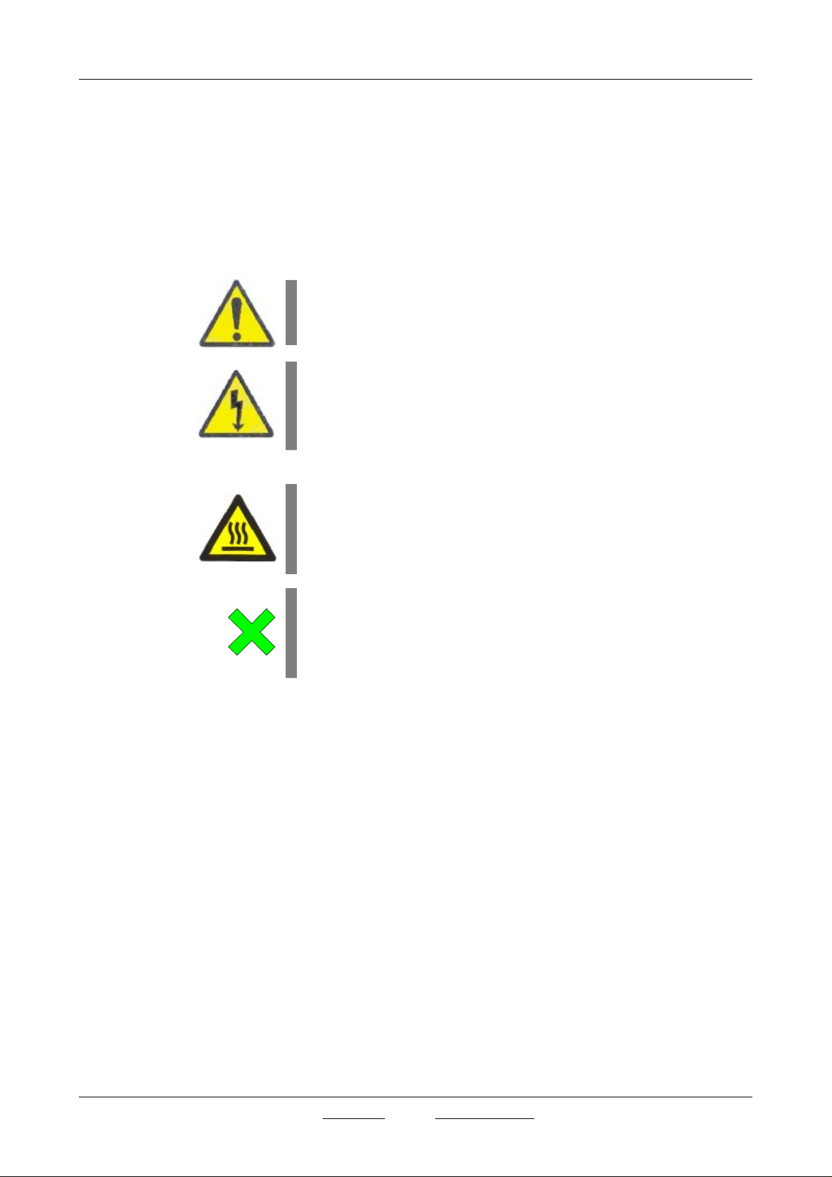
1.1 Iconos de seguridad
Identifican las situaciones de riesgo y las medidas de seguridad que deben
tomarse.
Los íconos hacen referencia al párrafo marcado con la línea gris.
Riesgo de peligro
Riesgo de peligro.
Respetar las instrucciones indicadas para realizar la operación descrita.
Riesgo eléctrico
Riesgo de accidente eléctrico al acceder a las zonas indicadas con esta señal
o en realizar las operaciones indicadas en este manual acompañadas de este
icono.
Respetar las instrucciones indicadas para realizar la operación descrita.
Riesgo de quemaduras por contacto con zonas a temperatura elevada.
La temperatura en la zona indicada con este icono puede exceder los 60ºC.
Utilizar guantes antitérmicos para realizar la operación descrita.
Respetar las instrucciones indicadas para realizar la operación descrita.
Información importante
• Información importante para obtener buenos resultados o para un
funcionamiento óptimo del equipo.
• Información importante para alargar la vida del equipo o evitar la
degradación de alguno de sus componentes.
1.2 Riesgos a los que está sometido el operador:
• Posibilidad de tocar piezas a una temperatura superior a 60ºC..
• Posible exposición a vapores.
• Riesgo eléctrico.
1.3 Cualificación del personal
Este equipo sólo puede ser utilizado por personal que ha sido cualificado
adecuadamente.
Este equipo sólo puede ser utilizado por personal que ha leido y comprendido estas instrucciones o ha sido cualificado adecuadamente en el funcionamiento de este equipo.
J.P. SELECTA s.a. Ctra. NII Km 585.1 Abrera 08630 (Barcelona) España Tel 34 937 700 877 Fax 34 937 702 362
e-mail: selecta @jpselecta.es - website: http://www.jpselecta.es

INSTRUCTION MANUAL CODE 80206.00 REV CJuly 2009 (It can be modified without notice) Page: 5
2 Información general para el usuario.
2.1 Requisitos legales para la instalación, utilización y
mantenimiento de un autoclave:
La normativa vigente de referencia sobre equipos a presión:
- Directiva 97/23/CE
- Reglamento de aparatos a presión RD 1244/1979 (España)
En el apartado 7 de este manual, se estableces los requisitos para su
instalación.
En el apartado 14 se establecen los requisitos para su mantenimiento.
2.2 Recepción del autoclave
Manipular el paquete de forma adecuada a su peso y considerandolo como
un equipo FRAGIL.
Desembalarlo y comprobar que el contenido coincide con lo indicado en el
apartado de la “Lista de embalaje”. Si se observa algún componente dañado
o la ausencia de alguno avisar rápidamente al distribuidor.
Conservar el embalaje original durante unos dias. Desechar el embalaje
adecuadamente, separando, sus componentes: Carton, madera y plástico.
2.3 Documentación
Junto con el autoclave se suminstran los siguientes documentos:
- Manual de instrucciones:
No instalar ni utilizar el equipo sin leer, previamente, este manual de instrucciones suminstrado.
Estas instrucciones forman parte inseparable del aparato y deben estar
disponibles a todos los usuarios del equipo
Cualquier duda debe ser consultada al suminstrador del autoclave.
- Declaración de conformidad CE:
Documento necesario para legalizar la instalación del autoclave.
- Prueba de funcionamiento:
Junto con el autoclave se entrega un registro que acredita su funcionamiento.
2.4 Otra información de interés
Los autoclave enviados J.P. SELECTA, s.a. para su reparación o mantenimiento deben estar descontaminadas.
Está prohibida cualquier modificación, eliminación o falta de mantenimiento
de cualquier dispositivo del autoclave.
Está prohibida la utilización en ambientes explosivos o con sustancias que
puedan desprender vapores o formar mezclas explosivas o inflamables.
Si este autoclave es utilizado de una manera que que no esté especificada
por J.P. SELECTA, s.a. la protección asegurada así como su funcionalidad
puede quedar comprometida.
2.5 Periodo de garantia
Los autoclave tienen una garantía de un año. La garantía no cubre los
daños causados por un uso indebido o por causas ajenas a J.P. SELECTA,
s.a.
Cualquier manipulación del aparato por personal no autorizado por J.P.
SELECTA, s.a., anula automáticamente los beneficios de la garantía.
J.P. SELECTA s.a. Ctra. NII Km 585.1 Abrera 08630 (Barcelona) España Tel 34 937 700 877 Fax 34 937 702 362
e-mail: selecta @jpselecta.es - website: http://www.jpselecta.es

MANUAL DE INSTRUCCIONES CODIGO 80206.00 REV C Julio 2009 (Sujetas a modificaciones sin previo aviso) Pag.: 6
3 Especificaciones técnicas
Volumen autoclave
30 50
Voltaje de red: I 230V I 230V
Potencia eléctrica: (W) 2800 3000
Intensidad máxima: (A) 12.5 14
Fusibles: (rápido. tipo H, dimensiones: 10x38mm) 20 20
Cable de conexión a red: Fase, Neutro, Tierra (sección 1mm2)
Peso (Kg Neto): 90 108
Medidas util (cm Ø x fondo) Ø30x40 Ø30x70
Medida ext: (cm Fondo x Ancho x Alto) 62x48x117 62x48x117
Volumen: (Litro) 30 50
Carga máxima: (Kg) (Metal) 8 12
Peso por soporte (Kg/cm2) Vacia 2 2.5
Peso por soporte (Kg/cm2) Carga + Agua 7.5 2.5
Espacio total que ocupa + puertas Añadir 1 m a la altura
Presión máxima de agua externa (bar) 2 2
Presión mínima de agua externa (bar) 0.5 0.5
Volumen de agua por ciclo (Litro) 1 1
Calidad del agua Desmineralizada entre 15 a 200 microS/cm; pH entre 5 y 7
Energia térmica transmitida al ambiente: (W/h) 525 600
Volumen depósito de agua: (Litro) 10 10
Racord entrada agua externa 3/4’’ 3/4’’
Filtro de entrada de aire Porosidad 0.20 micras
Nivel Acustico: Inferior a 70 dBA
Regimen de funcionamiento: Continuo con intervalos de 20 minutos entre cada ciclo.
Condiciones ambientales:
Uso en interiores.
Altitud hasta 2000m
Temperatura ambiente entre 5ºC y 40ºC.
Humedad relativa máxima 80% para temperaturas hasta 31ºC, disminuyendo linealmente hasta el 50% de
humedad relativa a 40ºC
Nivel de sobretensión: Categoría II
Grado de contaminación: 2
Material en contacto con el vapor: Acero inoxidable, Cobre, Teflon, Laton
Material Bastidor: Acero con recubrimiento
Material Cámara: Acero Inoxidable
Material Generador vapor: Acero Inoxidable.
Material tuberías: Cobre, Laton
Salida RS-232:Conector 9 pin macho. Pin 2 y 3 cruzados, pin 5 común. Velocidad 9600, sin paridad, 8 bits de
datos, 1 bit de stop.
J.P. SELECTA s.a. Ctra. NII Km 585.1 Abrera 08630 (Barcelona) España Tel 34 937 700 877 Fax 34 937 702 362
e-mail: selecta @jpselecta.es - website: http://www.jpselecta.es
INSTRUCTION MANUAL CODE 80206.00 REV CJuly 2009 (It can be modified without notice) Page: 7
Capacidad
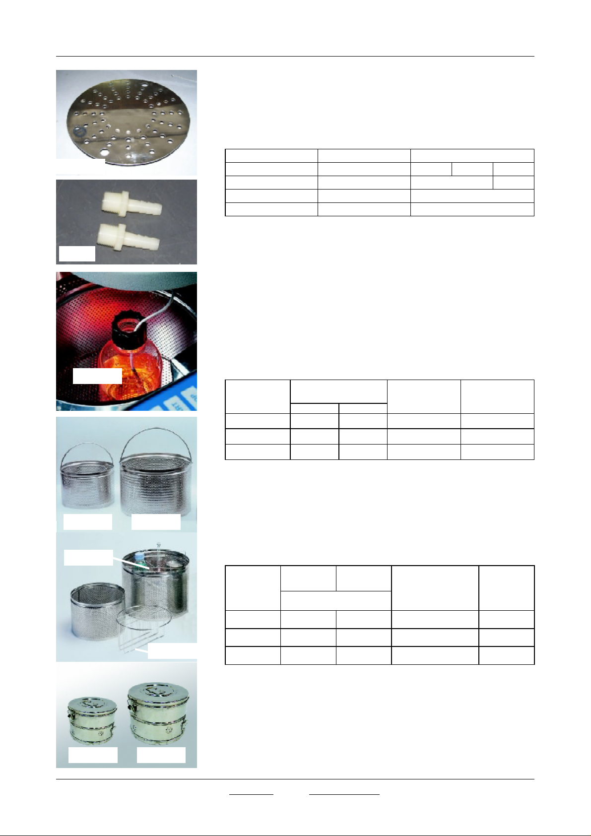
4 Lista de embalaje y accesorios
4.1 Contenido estandar del paquete
El equipo estándard consta de los siguientes componentes:
5600-5601
34100
4001219
Descripción Description
Autester ST DRY PV-II Autester ST DRY PV-II 4002514 4002515 4002425
Bandeja Shelf 5600
Racord vaciado Empying racord
Manual de instruciones Instruction manual
Código/Code
5601
34100
80206
4.2 Accesorios
• Impresora térmica de papel contínnuo con indicación de temperatura,
presión, tiempo, modalidad y estado. Código 4002417
• Sonda para lecturas de temperatura interior de la caldera, con dos
aplicaciones (Código 4001219) :
- Toma valores para registrador o termómetro
- Uso en programas de líquidos o en el interior de esterilización de
material embalado.
• Cestillos de alambre en acero AISI 316
Código cestillo
Basket code
1000495 28 20 4002514 2
1000495 28 20 4002515 3
1000496 38 28 4002425 2
Medidas (cm)
Dimensions (cm)
Ø Altura/Height
Para autoclave cod.
To autoclave code
Capacidad cestillos
Number of baskets
1000495 1000496
1002419
1002418
1002418 1002419
• Bastidores de alambre de acero inoxidable AISI 316
- Código: 1001217 Bastidor 4 compartimentos para cestillo 1000495
- Código: 1001218 Bastidor 6 compartimentos para cestillo 1000496
• Tambores de esterilización
Código
Code
Ø Alto
(cm)
Para autoclave cod.
To autoclave code
1002418 28 18 4002514 2
1002418 28 18 4002515 3
1002419 35 27 4002425 2
tambores
Drums
capacity
J.P. SELECTA s.a. Ctra. NII Km 585.1 Abrera 08630 (Barcelona) España Tel 34 937 700 877 Fax 34 937 702 362
e-mail: selecta @jpselecta.es - website: http://www.jpselecta.es

MANUAL DE INSTRUCCIONES CODIGO 80206.00 REV C Julio 2009 (Sujetas a modificaciones sin previo aviso) Pag.: 8
5 Introducción
Los autoclaves Autester ST DRY PV II son equipos versátiles destinados a un
àmplio espectro de aplicaciones en los campos, sanitàrios, procesos industriales y el control de calidad. Estos autoclaves permiten procesos de
esterilización de sólidos con y sin embalaje, liquidos, medios de cultivo y
priones. También permiten ciclos de desinfección así como secado.
5.2 Esterilización
Se entiende por esterilizar la destrución de o eliminación de toda forma de
vida -microbiana, incluyendo esporas- presente en objetos inanimados.
5.3 Desinfección
Se entiende por desinfección el proceso de destrución de agentes infecciosos. Se realiza a temperatura més baja que la esterilización. La Desinfección
consigue eliminar sólo algunas formas vegetativas.
5.4 Medios de cultivo
Material nutritivo en el que se pueden recuperar, multiplicar y aislar los
microorganismos, así como efectuar pruebas de suceptivilidad. Generalmente se presentan desecados en forma de polvo fino o granular, pero también
pueden presentarse hidratados y preparados. No deben utilizarse sin antes
ser esterilizados.
5.5 Priones
Los priones son partículas acelulares, patógenas y transmisibles. Se caracterizan por producir enfermedades que afectan al sistema nervioso central
(SNC). Los priones no son seres vivos, son partículas exclusivamente
proteicas sin ácido nucleico. Su acción patógena consiste en ser una forma
modificada de una proteína natural existente en el organismo que al entrar
en contacto con las proteínas originales las induce a adoptar la forma del
prión, que suele ser una forma anormal y disfuncional, todo ello en una
acción en cadena que acaba por destruir la operatividad de todas las
proteínas sensibles al prión.
5.6 Purgado (Extracción del aire de la camara)
El purgado es el ciclo mediante el cual se elimina el aire del interior de la
camara para conseguir vapor saturado.
5.7 Vapor saturado
Vapor de agua a una temperatura correspondiente al punto de ebullición del
liquido origen.
5.8 Purgado atmosférico
En el purgado atmosférico el aire sale al exterior de forma gravimètrica,
impusado por el vapor durante un tiempo determinado.
5.9 Purgado por vacío fraccionado
El purgado por vacío fraccionado combina el calentamiento de la caldera con
con la extracción de aire mediante bomba de vacío. Durante el ciclo de
purgado la caldera puede alcanzar dos veces o tres veces (según modo de
trabajo configurado) un alto nivel de vacío. La fiabilidad del pugado es
mayor que con el purgado atmostérico.
5.10 Test de Bowie Dick
El ensayo de Bowie Dick sirve para verificar el funcionamiento de los
esterilizadores de vapor de agua aplicable a los productos envueltos y cargas
porosas.
5.11 Test de vacío
Test destinado a verificar el funcionamiento de la bomba de vacío y la
estanqueidad de la la cámara y el circuito hidráulico durante un tiempo
determinado.
J.P. SELECTA s.a. Ctra. NII Km 585.1 Abrera 08630 (Barcelona) España Tel 34 937 700 877 Fax 34 937 702 362
e-mail: selecta @jpselecta.es - website: http://www.jpselecta.es

INSTRUCTION MANUAL CODE 80206.00 REV CJuly 2009 (It can be modified without notice) Page: 9
6 Descripción del equipo
Los autoclaves Autester ST DRY PV II de 30, 50 y 75 litros pertenecen a una
serie de autoclaves a vapor saturado que se distinguen por las siguientes
caraterísticas:
- Generador de vapor externo al depósito principal.
- No aptos para acomodar un modulo de esterilización.
- Ciclos para la esterilización de:
Carga de metal sin embalar: Pinzas, bisturies, ...
Carga de metal embalada y doble embalada.
Carga de caucho: Tubos, mangueras, cateteres,...
Carga de recipientes con líquidos.
- Desagüe del agua utilizada:
- Hacia el depósito para su reutilización.
- Hacia el desagüe de la instalación.
- Preparadas para funcionar con dos sondas. La instalación de la segunda
sonda (cód. 4001219) debe ser realizada en fábrica.
- Esta función es útil para la esterilización de líquidos.
- Registro de datos por impresora o salida externa RS-232 de lecturas de
temperatura, presión, tiempo y fase.
- Ciclos de Bowie-Dick y prueba de vacio, para verificación del funciona-
miento y validación.
- Regimen de funcionamiento
- Indicación de ciclo defectuso.
6.1 Características del diseño determinantes para la vida
del equipo
La temperatura máxima de servicio para este equipo es muy inferior a la
temperatura para la cual los materiales empleados presentan deterioro por
fluencia lenta.
- Fatiga: El equipo ha sido diseñado para resistir con seguridad la presión
máxima admisible PS = 2,5 bar, así como la fatiga en los materiales debida a
los ciclos de presión (de vacío hasta presión máxima). La vida teórica prevista
para el aparato es de 20 años, con régimen de trabajo de 4 operaciones/día
365 días año. En todo caso, la vida real del equipo queda supeditada a las
pruebas periódicas de cada 10 años y a las revisiones anuales.
- Corrosión: La utilización de acero inoxidable austenítico en la cámara del
autoclave garantiza una resistencia a la corrosión adecuada a la acción del
agua, vapor y productos a esterilizar
J.P. SELECTA s.a. Ctra. NII Km 585.1 Abrera 08630 (Barcelona) España Tel 34 937 700 877 Fax 34 937 702 362
e-mail: selecta @jpselecta.es - website: http://www.jpselecta.es

MANUAL DE INSTRUCCIONES CODIGO 80206.00 REV C Julio 2009 (Sujetas a modificaciones sin previo aviso) Pag.: 10
6.3 Modos y rangos de funcionamiento
El autoclave permite configurar el ciclo de esterilización de acuerdo a las
características de la carga a esterilizar:
Tabla. 6.3
Tabla. 6.4
TA
Tipo de programa Con sonda Sin sonda
exterior interior
Sólidos purgado atmosférico: 105-134ºC 105-130ºC
Sólidos dos fracciones: 115-134ºC 115-130ºC
Sólidos tres fracciones: 115-134ºC 115-130ºC
Líquidos purgado atmosférico: 105-134ºC 105-130ºC
Tiempo de esterilización: de 3 a 59 minutos
Tiempo de secado: de 0 a 99 minutos
6.4 Ciclos pre-establecidos
Los autoclaves Autester ST DRY PV II tienen 10 programas de trabajo
preestablecidos que pueden ser modificados en función de las necesitades
del usuario.
Programa Esterilización Secado Nº
TemperaturaTiempo Tiempode fracciones
ºC (minutos) de vacio *
0 Instrumental No embalado 134 4 10 2
1 Instrumental embalado 134 12 30 3
2 Priones 134 20 20 3
3 Delicado no embalado 121 15 15 2
4 Delicado embalado 121 30 30 3
5 Instrumental 126 12 25 3
6 Desinfección 105 25 15 1
7 Líquidos 121 30 - 1
8 Sólidos 121 15 30 1
9 Sólidos 134 4 30 1
* Tipos de purgado:
1.Purgado atmosférico
2.Purgado con dos fracciones de vacío
3.Purgado con tres fracciones de vacío
6.5 Programas de test
Los autoclaves Autester ST DRY PV II tienen 2 programas de test:
Test de Bowie Dick 134ºC 3’ 30’’
Tabla. 6.5
J.P. SELECTA s.a. Ctra. NII Km 585.1 Abrera 08630 (Barcelona) España Tel 34 937 700 877 Fax 34 937 702 362
e-mail: selecta @jpselecta.es - website: http://www.jpselecta.es
Test de Vacío 0.7 bar 5+ 10’

INSTRUCTION MANUAL CODE 80206.00 REV CJuly 2009 (It can be modified without notice) Page: 11
6.6 Elementos del Panel de mandos
5
2
1
Fig. 6.1 Panel de mandos
2
Fig. 6.7a
1.Display LCD indicador de parámetros
2.Selector monomando
3.Led indicador de marcha
4.Pulsador marcha / paro
5.Impresora (opcional)
3
4
1
6.7 Localización de los elementos principales
Fig. 6.7a
1. Maneta de cierre de la puerta
2. Interruptor general
Fig. 6.7b
1. Orificio de llenado del depósito de agua.
2
2. Junta de la puerta
Fig. 6.7b
Fig. 6.7c
1
Fig. 6.7c
1 2
1
2
3
1. Conector RS232 (puerto serie)
2. Conector sonda externa (Pt100)
Fig. 6.7d:
1. Válvula de seguridad
2. Válvula de vaciado vapor
4
3. Entrada de agua externa
4. Filtro de aireación
5. Termostatos de seguridad del generador de vapor.
6. Salida agua deposito de agua
7. Salida condensados
5
6
7
8. Válvula de desagüe.
8
Fig. 6.7d
J.P. SELECTA s.a. Ctra. NII Km 585.1 Abrera 08630 (Barcelona) España Tel 34 937 700 877 Fax 34 937 702 362
e-mail: selecta @jpselecta.es - website: http://www.jpselecta.es

MANUAL DE INSTRUCCIONES CODIGO 80206.00 REV C Julio 2009 (Sujetas a modificaciones sin previo aviso) Pag.: 12
7 Instalación
7.1 Emplazamiento
Situar el autoclave cerca de una toma de corriente adecuado al consumo de
la máquina.
De acuerdo a la legislación vigente (Ver 2) el autoclabe se debe
emplazar de forma que la salida de descarga de la válvula de seguri-
Fig. 7.1 Bloqueo ruedas
dad NO apunte a personas o pueda alcanzarlas en el caso de salida
de vapor.
En estos autoclaves la salida de la válvula de seguridad apunta hacia la parte
trasera.
Situar el autoclave sobre una superficie plana, horizontal y estable, adecuada
al peso de la máquina (Ver tabla 3) dejando un espacio libre de 20cm
alrededor de la máquina.
Para facilitar las operaciones de mantenimiento, se aconseja tener acceso
directo a todos los lados del autoclave.
Fig. 7.2 Salida vapor condensado.
Fig. 7.3 Entrada agua de red externa.
Inmovilizar el autoclave, ajustándolo al suelo, mediante los topes situados en
la parte anterior del aparato, previstos para tal efecto.
7.2 Instalación sin servicio de red de agua ni desagüe.
En este caso se debe aportar agua al deposito del autoclave de forma
manual.
Para recoger el agua proveniente de la condensación del vapor , colocar una
mangera (suministrada) desde la salida de condensados a un recipiente de
las siguientes características:
- Adecuado para soportar agua caliente hasta 80ºC.
- Altura máxima del recipiente: 30cm
- Debe estar situado en el suelo.
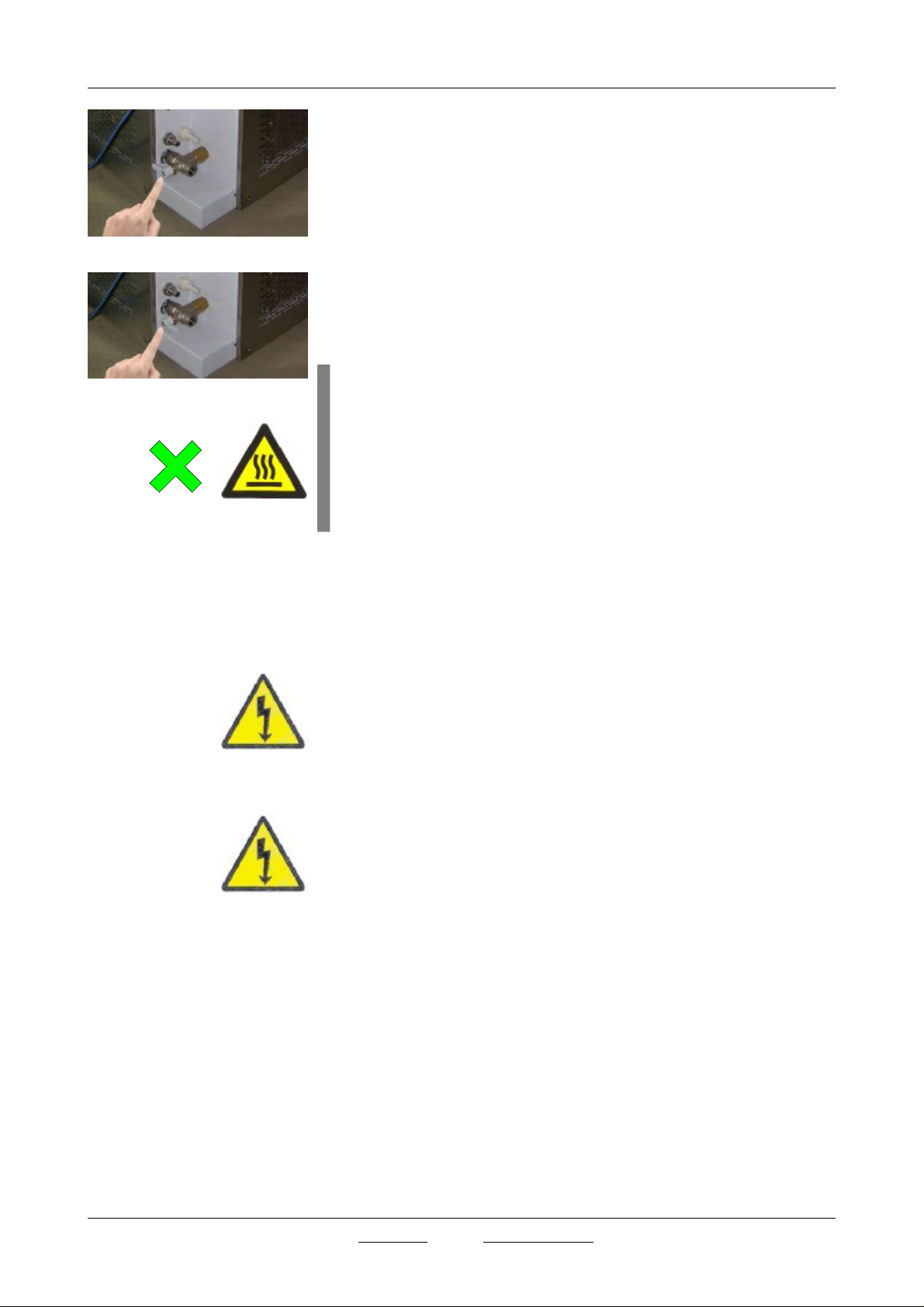
7.3 Instalación con servicio de agua de red y de desagüe
El autoclave tomará agua de la red exterior, de forma automática, cuando
detecte un nive bajo de agua en su depósito.
La conexión a la red exterior mediante una toma de 3/4". Ver foto
La presión de suministro nunca debe ser superior a 2bar.
Debe activarse este modo de funcionamiento mediante el panel de mandos.
Ver apartado 9.6.
ATENCIÓN
No usar la opción de vaciado exterior sin antes haber conectado una manguera de presión.
Fijar la manguera de manera que no pueda moverse por efecto de la presión
al final del ciclo.
No sujetar la manguera con las manos. Esta manguera puede alcanzar
temperaturas superiores a 60ºC.
J.P. SELECTA s.a. Ctra. NII Km 585.1 Abrera 08630 (Barcelona) España Tel 34 937 700 877 Fax 34 937 702 362
e-mail: selecta @jpselecta.es - website: http://www.jpselecta.es
INSTRUCTION MANUAL CODE 80206.00 REV CJuly 2009 (It can be modified without notice) Page: 13
7.4 Selección del sistema de desagüe:
Con la válvula selectora indicada en 7.4a y b
7.4.1 Reutilización del agua (Fig 7.4a)
Situar el mando de la válvula señalándolo hacia el interior de la máquina.
7.4.2 Expulsar el agua al exterior (Fig 7.4b)
Fig. 7.4a Reutilización del agua.
Al final de cada proceso de esterilizado, colocar el mando de dicha válvula
en dirección al exterior.
Fijar una manguera con la ayuda de la espiga acanada 34100 (Ver 4.1) de
salida de la válvula y fijar también el otro extremo a un recipiente o
desague, procurando NO OBSTRUIR EL TUBO.
¡ATENCIÓN!
La salida de vapor por la válvula de seguridad y la salida de
Fig. 7.4b Expulsión del agua.
vapor y agua por la tetina de la válvula (Fig 7.4b) es a
PRESIÓN y a TEMPERATURA ELEVADA.
Tome precauciones para evitar GRAVES QUEMADURAS.
NO SUJETAR LA MANGUERA COLOCADA EN LA SALIDA de
agua (Fig 7.4b) CON LA MANO YA QUE PUEDE CAUSAR
QUEMADURAS.
7.5 Conexión a la red eléctrica:
Los autoclaves se suministran sin clavija de conexión a la red electrica.
Se recomienda su conexión directa a la red a través de una caja de bornes.
Delante de la caja de bornes se debe instalar un interruptor automático
bipolar ICP sobredimensionado 1.5 veces la corriente máxima del autoclave.
Consultar las el tipo y nivel de la tensión de alimentación y el valor
máximo de intensidad en la placa de carateristicas del equipo.
El interruptor automático debe estar situado en un punto accesible de forma
rápida y sin obstaculos.
7.5.1 Puesta a tierra de protección
La instalación de suminstro de energia electrica para el autoclave DEBE
tener conductor de tierra de protección.
La protección contra los riesgos electricos del autoclave necesita que el cable
de red, marcado con color Amarillo-verde, esté conectado en el conductor de
tierra de la instalación.
7.6 Legalización de la instalación: (ESPAÑA)
De acuerdo con las disposiciones del Art. 14 del Reglamento de Aparatos a
Presión, la instalación del autoclave debe ser legalizada por un instalador
autorizado para esta clase de instalaciones.
Puede obtener una lista de instaladores autorizados consultando al
deparatmento de industria del gobierno de su comunidad autónoma.
En otros paises debe consultarse los requisitos de la instalación con el
organismo competente.
J.P. SELECTA s.a. Ctra. NII Km 585.1 Abrera 08630 (Barcelona) España Tel 34 937 700 877 Fax 34 937 702 362
e-mail: selecta @jpselecta.es - website: http://www.jpselecta.es

MANUAL DE INSTRUCCIONES CODIGO 80206.00 REV C Julio 2009 (Sujetas a modificaciones sin previo aviso) Pag.: 14
8 Funcionamiento
ATENCION
EL AUTOCLAVE SE SUMINISTRA CON LA PUERTA DE LA CAMA-
RA CERRADA.
LA APERTURA DE LA PUERTA SOLO ES POSIBLE ACTIVANDO LA
ALIMENTACIÓN ELECTRICA DEL AUTOCLAVE.
8
8.1 Operaciones preliminares a la puesta en marcha
- Poner en marcha mediante el interruptor general (Fig 6.7).
- Llenar el depósito (Ver Fig 8.1) de agua con unos 8 litros .
Comprobar, visualmente, mediante el nivel de agua de la parte frontalizquierda, la altura del agua del deposito.
Es aconsejable cambiar el agua después de 50 usos ó 1 vez al mes
- Comprobar que esté cerrada la válvula de vaciado vapor(12).
- Colocar la bandeja en el fondo de la caldera.
- Colocar el material a esterilizar.
- Cerrar la puerta.
Nota:
Cuando el autoclave esté fría, antes de su puesta en marcha realizar un
precalentamiento de entre 10 y 15 minutos.
Para realizar el precalentamiento:
Enchufar, pulsar el interruptor general y dejar la máquina encendida durante
los 10-15 minutos.
8.1.1 Apertura y cierre de la puerta de carga y descarga:
Existen dispositivos de seguridad que bloquean la apertura de la puerta si no
existen las condiciones de seguridad para hacerlo.
- La apertura y cierre de la puerta deben ser efectuados por personal
previamente informado.
¡ATENCION!
Peligro de quemaduras
graves
A la finalización del ciclo, la
carga de la cámara puede
estar a temperatura elevada.
Utilizar guantes de protec-
ción térmica pa extraer la
carga de la cámara.
- Antes de abrir la puerta el operador se asegurará que el ciclo del autoclave ha terminado y de que no existe presión en la cámara.
8.1.2 Precauciones durante la utilización:
Se vigilarán periódicamente las indicaciones del display LCD del equipo. No La
presión no debe superar nunca la presión máxima admisible (PS = 2,5 bar)
J.P. SELECTA s.a. Ctra. NII Km 585.1 Abrera 08630 (Barcelona) España Tel 34 937 700 877 Fax 34 937 702 362
e-mail: selecta @jpselecta.es - website: http://www.jpselecta.es
INSTRUCTION MANUAL CODE 80206.00 REV CJuly 2009 (It can be modified without notice) Page: 15
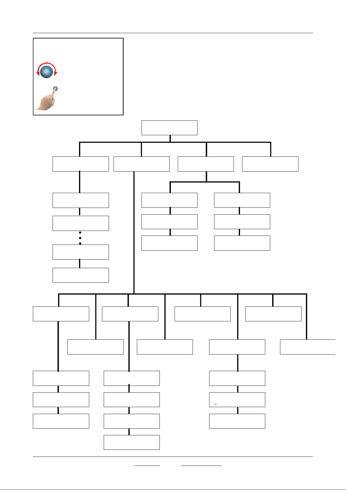
Fig 9.1: El Monomando tiene dos
movimientos:
- Giro: Selecciona las
diferentes opciones del
menú.
- Pulsar: Ejecuta la
opción apuntada.
PROG/
PROGRAMS
PROG/P0 SOLID2
134 C 04 DRY 18
9 Menu de selección de ciclos,
parámetros y configuración
Una vez pulsado el interruptor general (Ver Fig. 6.7), el display muestra
durante unos segundos un mensaje indicando la versión del software del
controlador.
A continuación aparece el mensaje por defecto que corresponderá al último
programa utilizado.
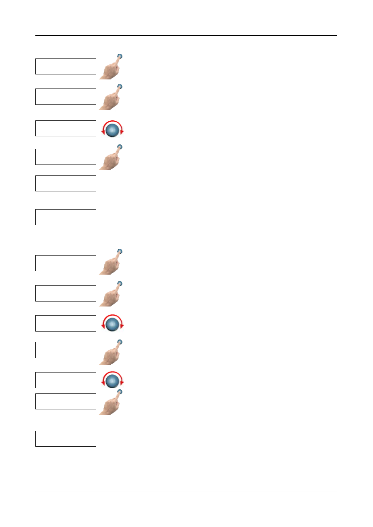
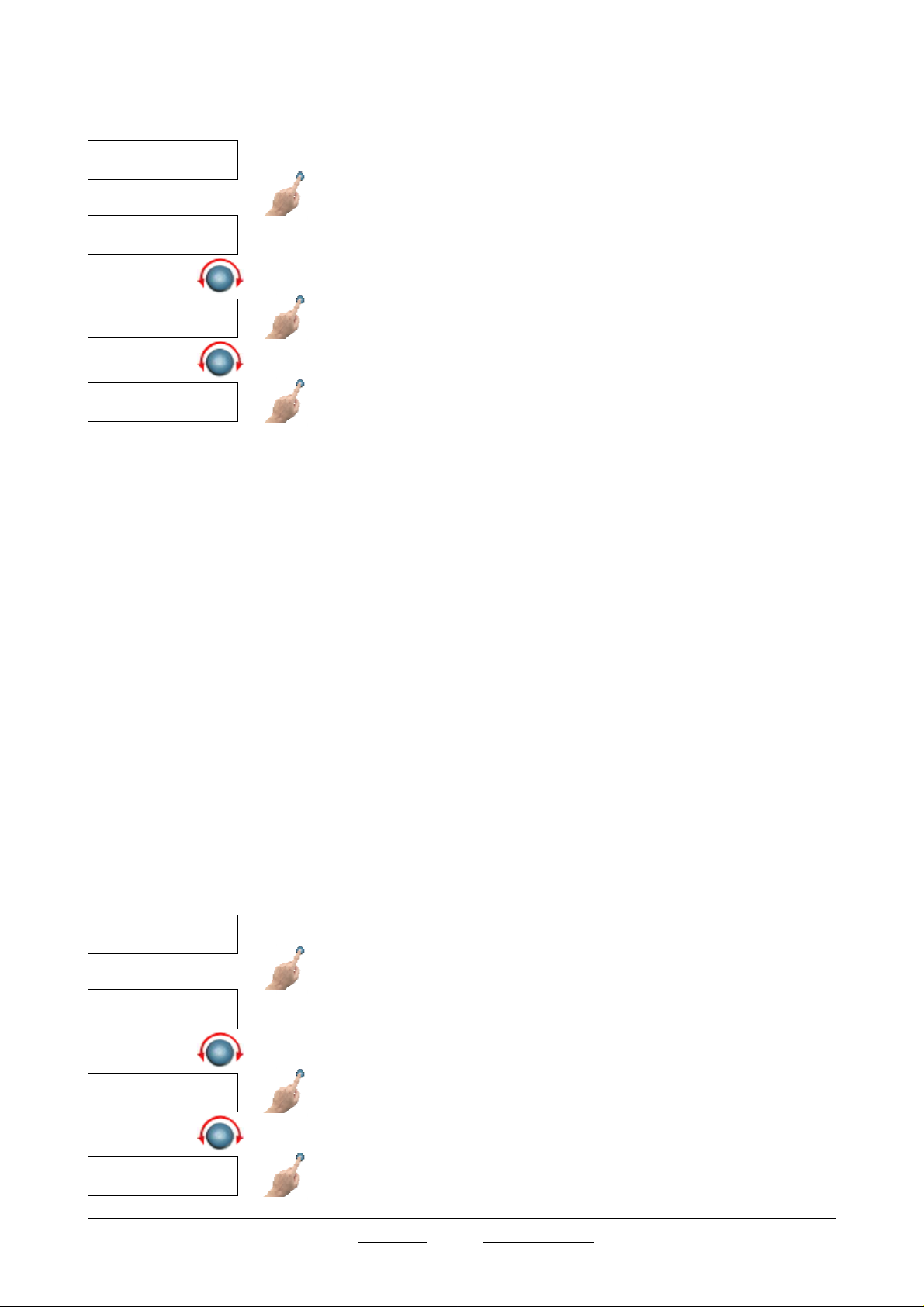
Todas las funciones se seleccionan mediante el monomando: Ver Fig 9.1
P0 134 C DRY 10
SOLID 2 PRESS START
CONF/
CONFIGURATION
TEST/VAC OFF
VACUM TEST
TEST/
TEST
EXIT
TEST/DCK OFF
BOWIE DICK TEST
PROG/P1 SOLID3
134 C 12 DRY 38
PROG/P9 SOLID1
134 C 04 DRY 30
EXIT
CONF/LNG
LANGUAGE
CONF/UNI> T(C) >
UNITS
CONF/LNG
LANGUAGE
VACUM TEST
PRESS START
EXIT EXIT
CONF/PRN
PRINTER
CONF/WTR
EXTERNAL WATER
CONF/PRN/SET OFF
PRINTER STATUS
BOWIE DICK TEST
PRESS START
CONF/PRB
EXTERNAL PROBE
CONF/CLK
CLOCK
CONF/CLK/DAT
CHANGE DATE
CONF/PWD
PASSWORD
EXIT
CONF/LNG/ENG>
ENGLISH
EXIT
J.P. SELECTA s.a. Ctra. NII Km 585.1 Abrera 08630 (Barcelona) España Tel 34 937 700 877 Fax 34 937 702 362
CONF/PRN/INT 01
PRINT INTERVAL
CONF/PRN/FED/FEED
PRESS BUTTON
EXIT
e-mail: selecta @jpselecta.es - website: http://www.jpselecta.es
CONF/CLK/DAT
20/02/2007 12:16:12
EXIT
MANUAL DE INSTRUCCIONES CODIGO 80206.00 REV C Julio 2009 (Sujetas a modificaciones sin previo aviso) Pag.: 16
9.1 Selección del ciclo
P0 134 C DRY 10
SOLID 2 PRESS START
PROG/
PROGRAMS
PROG/P0 SOLID2
134 C 04 DRY 10
PROG/P1 SOLID3
134 C 12 DRY 38
SELECT
P1 134 C DRY 38
SOLID 3 PRESS START
Pulsar el botón monomando, apareciendo en la pantalla «PROGRAMS».
Pulsar nuevamente para entrar en la selección de ciclos.
Girar el botón monomando hasta encontrar el ciclo deseado.
Una vez encontrado el ciclo pulsar el botón monomando.
Aparece «SELECT», pulsar de nuevo para validar.
Aparece durante unos segundos la pantalla de confrimación «SELECTED»
Finalmente aparecerá la pantalla por defecto con el programa seleccionado.
Pulsar el pulsador de marcha/paro, se encenderá el LED y el equipo se
pondrá en marcha.
P0 134 C DRY 10
SOLID 2 PRESS START
PROG/
PROGRAMS
PROG/P0 SOLID2
134 C 04 DRY 10
PROG/P1 SOLID3
134 C 12 DRY 38
SELECT
MODIFY
P1 134 C DRY 38
SOLID 3 PRESS START
9.2 Modificación de Programa
Este menu permite modificar los parámetros de un ciclo. Todos los ciclos son
modificables. (Ver 6.3 para los limites de cada parametro de un ciclo)
A través del menú «PROGRAMS» pulsamos el monomando para acceder a
los diferentes programas.
Girando el botón podemos colocarnos en el número de programa que mas se
adapta a nuestras necesidades y para poderlo modificar.
Pulsando el botón monomando aparecerá «SELECT».
Giramos el botón para que aparezca «MODIFY», volvemos a pulsar el botón,
aparecerá en pantalla el programa que queremos modificar.
Para modificar un parametro: seleccionarlo girando el monomando, confirmar pulsando, modificar girando y confirmar pulsando.
Una vez modificado el programa pulsamos el botón y aparecerá «SELECT»,
pulsamos nuevamente para validar, aparecerá durante unos segundos la
pantalla «SELECTED».
Finalmente aparecerá la pantalla por defecto con el programa seleccionado.
Pulsar el pulsador de marcha/paro, se encenderá el LED y el equipo se
pondrá en marcha.
J.P. SELECTA s.a. Ctra. NII Km 585.1 Abrera 08630 (Barcelona) España Tel 34 937 700 877 Fax 34 937 702 362
e-mail: selecta @jpselecta.es - website: http://www.jpselecta.es
INSTRUCTION MANUAL CODE 80206.00 REV CJuly 2009 (It can be modified without notice) Page: 17
9.3 Modificación del Idioma
CONF/
CONFIGURATION
CONF/LNG/
LANGUAGE
CONF/UNIT/ENG>
ENGLISH
EXIT
Girar el monomando hasta que aparezca en pantalla el menú
«CONFIGURATION»; pulsar de nuevo el monomando y aparecerá el
submenú «LANGUAGE».
Pulsar el botón y en pantalla aparecerá el idioma que esté memorizado por
defecto. Girar hasta visualizar el idioma deseado y pulsar el botón para
validarlo; aparecerá durante unos segundos en pantalla «SELECTED».
Volver a girar el botón hasta que aparezca «EXIT».
Pulsar el botón monomando, aparecerá en pantalla «CONFIGURATION».
Girar el botón monomando hasta que aparezca en pantalla «EXIT».
CONF/
CONFIGURATION
9.4 Configuración. Cambio ºC a ºF
Girar el botón monomando hasta que aparezca en pantalla
«CONFIGURATION».
CONF/LNG/
LANGUAGE
Pulsar el botón monomando. Aparece la pantalla «LANGUAGE».
Girar el botón hasta que aparezca el submenú «UNITS».
Pulsar el botón monomando y cambiará de grados Celsius a Farenheit.
CONF/UNIT/ T (C)
UNITS
EXIT
J.P. SELECTA s.a. Ctra. NII Km 585.1 Abrera 08630 (Barcelona) España Tel 34 937 700 877 Fax 34 937 702 362
e-mail: selecta @jpselecta.es - website: http://www.jpselecta.es
Volver a girar el botón hasta que aparezca «EXIT».

MANUAL DE INSTRUCCIONES CODIGO 80206.00 REV C Julio 2009 (Sujetas a modificaciones sin previo aviso) Pag.: 18
9.5 Configuración Impresora
CONF/
CONFIGURATION
CONF/LNG/
LANGUAGE
CONF/PRN/
PRINTER
CONF/PRN/SET OFF
PRINTER STATUS
CONF/PRN/INT 01
PRINT INTERVAL
CONF/PRN/FED/FEED
PRESS BUTTON
Para poder activar y configurar la impresora partir del menú «CONFIGURACIÓN» y pulsar el momando.
Aparece en pantalla «LANGUAGE». Girar el botón hasta que aparezca el
submenú «PRINTER».
Pulsar el botón monomando, aparece en pantalla «PRINTER STATUS».
En esta pantalla se indica el estado de la impresora (ON ó OFF).
Pulsando el monomando se Activa/desactiva la impresora.
Girar el botón monomando y aparecerá en pantalla «PRINT INTERVAL».
Pulsar el monomando y girar para cambiar el tiempo en minutos. Aceptar
pulsando de nuevo.
Girar el botón monomando. Aparecerá en pantalla «PRESS BUTTON».
Esta función realiza un avance del papel de la impresora cada vez que se
pulsa el monomando.
Esto se utiliza durante el cambio del rollo de papel.
EXIT
CONF/
CONFIGURATION
CONF/LNG/
LANGUAGE
CONF/WTR/ OFF
EXTERNAL WATER
Girar el botón monomando y hasta que aparezca en pantalla «EXIT».
Pulsar de nuevo para salir al menu «CONFIGURATION».
9.6 Activar/Desactivar la entrada de agua externa
Si ha instalado el autoclave para llene su deposito, automaticamente de una
red externa (Ver 7.4) debe configuranse esta función.
Partir del menu «CONFIGURATION». Pulsar el monomando para entrar.
Aparece «LANGUAGE. Girar hasta «EXTERNAL WATER»
En esta pantalla se indica el estado de la valvula de entrada de agua externa: Abierta (ON) o cerrada (OFF).
Pulsando el monomando se Abre/Cierra la impresora.
Girar el monomando hasta «EXIT» y pulsar.
EXIT
J.P. SELECTA s.a. Ctra. NII Km 585.1 Abrera 08630 (Barcelona) España Tel 34 937 700 877 Fax 34 937 702 362
e-mail: selecta @jpselecta.es - website: http://www.jpselecta.es
Repetir para salir a la pantalla principal.

INSTRUCTION MANUAL CODE 80206.00 REV CJuly 2009 (It can be modified without notice) Page: 19
9.7 Activa/Desactivar la sonda exterior de temperatura.
CONF/
CONFIGURATION
CONF/LNG/
LANGUAGE
Si ha instalado la segunda sonda, para ciclos de esterilización de líquidos (Ver
7) debe configuranse esta función.
Partir del menu «CONFIGURATION». Pulsar el monomando para entrar.
Aparece «LANGUAGE. Girar hasta «EXTERNAL PROBE»
CONF/WTR/ OFF
EXTERNAL WATER
EXIT
En esta pantalla se indica el estado de la sonda externa: Activada(ON) o
Desactivada (OFF).
Pulsando el monomando se Activa/desactiva la sonda externa.
Girar el monomando hasta «EXIT» y pulsar.
Repetir para salir a la pantalla principal.
9.8 Ajustar fecha y hora.
CONF/
CONFIGURATION
CONF/LNG/
LANGUAGE
CONF/CLOCK/ OFF
CLOCK
CONF/CLK/DAT
CHANGE DATE
CONF/CLK/DAT
20/02/2007 12:16:12
CONF/CLK/DAT
EXIT
J.P. SELECTA s.a. Ctra. NII Km 585.1 Abrera 08630 (Barcelona) España Tel 34 937 700 877 Fax 34 937 702 362
e-mail: selecta @jpselecta.es - website: http://www.jpselecta.es
Utilizar este menu para actualizar la hora y la fecha del reloj del autoclave.
Partir del menu «CONFIGURATION». Pulsar el monomando para entrar.
Aparece «LANGUAGE.
Girar hasta «CLOCK»
Pulsar el monomando, aparece «CHANGE DATE»
Aparece la fecha y la hora.
Para modificar el dia, mes, año,... seleccionarlo girando el monomando,
confirmar pulsando, modificar girando y confirmar pulsando.

MANUAL DE INSTRUCCIONES CODIGO 80206.00 REV C Julio 2009 (Sujetas a modificaciones sin previo aviso) Pag.: 20
CONF/
CONFIGURATION
TEST/
TEST
TEST/VAC> OFF
VACUUM TEST
TEST/VAC> ON
VACUUM TEST
VACUM TEST
PRESS START
9.9 Ensayo test vacío
Para poder realizar la prueba de vacío seguir los siguientes pasos:
Pulsar el botón monomando hasta que aparezca en pantalla el menú «TEST»
Pulsar el botón monomando y aparecerá en pantalla «VACUUM TEST».
Volver a pulsar de nuevo para seleccionar el test de vacío «ON».
Pulsar el botón y aparecerá en pantalla «PRESS START». La máquina está
preparada para realizar el test de vacio pulsando el pulsador start/stop (4),
poniéndose el LED indicador (3) en marcha.
PROG/
PROGRAMS
CONF/
CONFIGURATION
TEST/
TEST
TEST/VAC> OFF
VACUUM TEST
TEST/DCK> OFF
BOWIE DICK TEST
EXIT
BOWIE DICK TEST
PRESS START
9.10 Ensayo test Bowie-Dick
Para poder realizar la prueba de Bowie-Dick seguir los siguientes pasos:
Pulsar el botón monomando hasta que aparezca en pantalla el menú
«PROGRAMS».
Girar el botón monomando hasta que aparezca en pantalla «TEST».
Pulsar el botón monomando y aparecerá en pantalla «VACUUM TEST», girar
el botón monomando hasta que aparezca «BOWIE-DICK».
Pulsar para validar la prueba de BOWIE-DICK «ON».
Girar el botón monomando hasta que aparezca «EXIT».
Pulsar el botón y aparecerá en pantalla «PRESS START». La máquina está
preparada para realizar el test de Bowie-Dick pulsando el pulsador start/stop
(4), poniéndose el LED indicador (3) en marcha.
J.P. SELECTA s.a. Ctra. NII Km 585.1 Abrera 08630 (Barcelona) España Tel 34 937 700 877 Fax 34 937 702 362
e-mail: selecta @jpselecta.es - website: http://www.jpselecta.es

INSTRUCTION MANUAL CODE 80206.00 REV CJuly 2009 (It can be modified without notice) Page: 21
10 Actuación en caso de fallo en la ejecución del ciclo.
El sistema de control del autoclave tiene la capacidad de identificar un
funcionamiento incorrecto del ciclo.
En caso de que el ciclo se interrumpa, por ejemplo: por fallo de suministro
electrico, por falta agua, etc... debe considerarse que la carga no ha sido
esterilizada y debe repetirse la esterilización.
Como norma general: Desconectar el autoclave, por el interruptor general,
esperar unos segundos, y poner en marcha de nuevo.
Si la puerta está bloqueada, esperar unos 20 minutos a que la temperatura
de la cámara descienda espontaneamente.
Puede accelerarse el proceso abriendo la valvula manual de
despresurización. (Cerrar la valvula antes de poner en marcha de nuevo)
Pantalla Error Descripción
ERROR 01!
E2PROM FAIL
ERROR 02!
PRESSURE SENSOR FAIL
WATER TANK EMPTY
DOOR OPEN
ERROR 13!
OVERPRESSURE
ERROR 14!
VACUUM FAIL
ERROR 15!
PRESSURE FAIL
ERROR 16!
INTERNAL OVERTEMP.
ERROR 17!
EXTERNAL OVERTEMP.
ERROR 18!
STERILIZATION FAIL
ERROR 19!
SETPOINT UNREACHABLE
01Error EEPROM defectuoso.
02Error del sensor de presión.
Sensor defectuoso o cable cortado.
10Depósito de agua vacío.
12Puerta abierta.
13Sobrepresión. Se ha superado la presión máxima de +2.5bar.
14Error de vacío. Hay una fuga o la bomba está averiada.
15Error de presión durante las fracciones.
No queda agua o resistencia defectuosa.
16Sobretemperatura en la caldera. Se ha superado los 150ºC en el interior.
17Sobretemperatura en la faja. Se ha superado los 150ºC en el exterior.
18Error de esterilización. Se han superado los márgenes de consigna o queda
aire en el interior.
19No se llega a la consigna. No queda agua o la resistencia está defectuosa.
ERROR 20!
EMPTY TOO LONG
ERROR 21!
PRINTER PAPER END
ERROR 22!
PRINTER ERROR
ERROR 23!
POWER FAIL
ERROR 26!
TEST FAILED
J.P. SELECTA s.a. Ctra. NII Km 585.1 Abrera 08630 (Barcelona) España Tel 34 937 700 877 Fax 34 937 702 362
e-mail: selecta @jpselecta.es - website: http://www.jpselecta.es
20Tarda demasiado tiempo en vaciar la presión y el agua de la caldera.
Válvulas o conductos obstruidos.
21Se ha acabado el papel de la impresora.
22Error de la impresora. Posiblemente se halla atascado el papel.
23Error de alimentación (Se detecta en la puesta en marcha).
26Error en el test de vacío.

MANUAL DE INSTRUCCIONES CODIGO 80206.00 REV C Julio 2009 (Sujetas a modificaciones sin previo aviso) Pag.: 22
11 Recomendaciones para lograr una
perfecta esterilización
El material a esterilizar, tiene que estar perfectamente limpio, libre cualquier
tipo incrustación o residuo, para ello es recomendable lavarlo con un buen
detergente y agua destilada. Después aclarar con abundante agua.
No cargar en exceso las bandejas, gradillas o cestillos, procurando dejar
siempre un espacio entre ellos de 1 ó 2 cm, a fin de favorecer el paso del
vapor y facilitar el secado.
11.1 Esterilización de instrumentos a granel:
Colocar el instrumental sobre el papel hidrófugo en posición abierta y que no
se toquen entre sí.
Evitar colocar en una misma bandeja instrumental de diferente tipo de
metal.
11.2 Esterilización de instrumental en bolsas:
No debe de haber más de un instrumento por bolsa.
Colocar las bolsas sobre papel hidrófugo, en posición vertical que no se
toquen entre sí ni tampoco las paredes del autoclave.
11.3 Esterilización de Tubos:
Los tubos deben estar perfectamente limpios, aclarados y escurridos.
Colocar los tubos, a poder ser, abiertos por ambos lados.
Procurar que los tubos no toquen la pared del autoclave, ni que formen
dobleces que obstruyan el diámetro interior.
11.4 Esterilización de Recipientes:
Nunca colocar recipientes herméticamente cerrados.
Colocar los recipientes boca abajo para evitar los depósitos de agua.
11.5 Esterilización de Líquidos:
Colocar los líquidos a esterilizar en recipientes preparados para soportar la
temperatura de esterilización y encima de bandejas, para que se puedan
recoger posibles derrames.
Los recipientes se llenarán sobre los 2/3 de su capacidad. NO CERRARLOS
herméticamente, se taparán con algodón o algún tipo de tapón que facilite
la salida de aire del recipiente y no se forme presión.
Evitar utilizar recipientes de cuello estrecho.
Al final del ciclo de esterilización, dejar que el autoclave se enfríe libremente
(hasta que la presión sea 0 kg/cm²).
J.P. SELECTA s.a. Ctra. NII Km 585.1 Abrera 08630 (Barcelona) España Tel 34 937 700 877 Fax 34 937 702 362
e-mail: selecta @jpselecta.es - website: http://www.jpselecta.es

INSTRUCTION MANUAL CODE 80206.00 REV CJuly 2009 (It can be modified without notice) Page: 23
12 Dispositivos de seguridad
El autoclave está provisto de los siguientes dispositivos de seguridad:
12.1 Presostato de Seguridad: Ajustado a 2.35bar
Corta la alimentación electrica del generador de vapor (o resistencia
electrica) para detener la producción de vapor cuando se produce una
sobrepresión anormal en la cámara de esterilización.
12.2 Válvula de Seguridad: Ajustada a 2.5 bar
En el caso de que la presión de la cámara supere los 2.5bar, esta válvula se
abre automáticamente, para liberar el vapor del interior de la cámara y, en
consecuencia, despresurizar la cámara.
En caso de disparo de la válvula de seguridad debe detenerse el uso del
autoclave y avisar al servicio técnico.
12.3 Termostato de seguridad: Sin posibilidad de ajuste.
Cuando se produce una elevación anormal de temperatura o un descenso
considerable del nivel de agua (con la consiguiente sobretemperatura en el
generador de vapor), entra en funcionamiento el termostato de seguridad
(14) parando la calefacción.
Este termostato no puede rearmarse, debe detenerse el uso del autoclave y
avisar al servicio técnico.
12.4 Bloqueo de la puerta. con Tª > 98ºC
En caso de bloqueo de la apertura de la puerta por avería del sistema de
seguridad seguir el siguiente protocolo:
1 Parar la máquina.
2 Desenchufarla de la red.
3 Poner un tubo en la válvula de aireación (11).
4 Abrir la válvula con cuidado para que salga el vapor. Tomar las precaucio-
nes necesarias para evitar quemaduras.
5 Esperar el total vaciado del vapor.
6 Con el tirador suministrado con la máquina proceder de la siguiente
manera (ver fotos):
Mirar con la ayuda de una linterna en el interior de la rejilla de apertura de
la tapa; localizar el mecanismo de cierre y verá la palanca de apertura del
mismo.
Una vez localizado introducir el tirador en la rejilla con cuidado y desplazar la
palanca hacia el exterior. Mantener la palanca en esta posición mientras
abrimos simultáneamente la tapa mediante la maneta de la puerta.
J.P. SELECTA s.a. Ctra. NII Km 585.1 Abrera 08630 (Barcelona) España Tel 34 937 700 877 Fax 34 937 702 362
e-mail: selecta @jpselecta.es - website: http://www.jpselecta.es

MANUAL DE INSTRUCCIONES CODIGO 80206.00 REV C Julio 2009 (Sujetas a modificaciones sin previo aviso) Pag.: 24
CONF/
CONFIGURATION
CONF/PWD
PASSWORD
CONF/PWD/ENT> 0000
ENTER PASSWORD
CONF/PWD/ENT> OK
ENTER PASSWORD
CONF/PWD/CHG> 0000
CHANGE PASSWORD
CONF/PWD/DIS> NO
DISABLE PASSWORD
EXIT
13 Calibraciones
Este apartado describe los parámetros modificables a través del menu de
calibración. Estos parámetros deberian cambiarse sólo cuando los valores
iniciales seleccionados no satisfagan las necesidades de las aplicaciones.
Acceso al menu de calibración:
Pulsar el botón monomando y seleccionar el menu CONFIGURATION dentro
del menu «PROGRAMS».
Pulsar nuevamente y aparecerá en pantalla «LANGUAGE», giraremos el
botón hasta que aparezca en pantalla «PASSWORD».
Pulsar el botón para entrar en «ENTER PASSWORD», el código por defecto
es «0000» (el usuario puede cambiar la contraseña si lo desea a través de
«CHANGE PASSWORD»); pulsar nuevamente y aparecerá «ENTER
PASSWORD OK», girar el botón monomando hasta«EXIT».
CONF/
CONFIGURATION
CALI/
CALIBRATION
CALI/ITMP> + 0.0 C
INTERNAL TEMP.
CALI/ITMP> + 0.0 C
EXTERNAL TEMP.
CALI/PRES>+00.0BAR
PRESSURE
CALI/PREH>+00.0BAR
PREHEAT
Pulsar el bmonomando hasta «CONFIGURATION», girar hasta
«CALIBRATION», pulsar el botón para entrar dentro de los submenús
siguientes:
«INTERNAL TEMP»: Introduce una corrección (constante) en la medida de la
temperatura.
«EXTERNAL TEMP»: Introduce una corrección (constante) en la medida
temperatura de la segunda sonda.
«PRESSURE»: Introduce una corrección (constante) en la medida de la
presión.
«PREHEAT»: Introduce Introduce una corrección (constante) en la temperatura de la calefacción de la caldera (Resistencia de faja).
«COUNTER» Contador del numero de ciclos ejecutados por el autoclave.
En estos submenús nos permite modificar el cero de las sondas de tempera-
tura y presión, cambiar la consigna de la temperatura de la faja de cada
programa y ver el número de esterilizaciones realizada por la máquina.
Girar el monomando hasta encontrar «EXIT», pulsar el monomando y hasta
«CONFIGURATION» , girar nuevamente hasta que aparezca «EXIT».
CALI/CNTR> 000020
COUNTER
EXIT
J.P. SELECTA s.a. Ctra. NII Km 585.1 Abrera 08630 (Barcelona) España Tel 34 937 700 877 Fax 34 937 702 362
e-mail: selecta @jpselecta.es - website: http://www.jpselecta.es
Pulsaremos el botón y volveremos a la pantalla principal.

INSTRUCTION MANUAL CODE 80206.00 REV CJuly 2009 (It can be modified without notice) Page: 25
14 Mantenimiento
Antes de quitar la tapa envolventes del aparato desconectarlo
de la red eléctrica.
Cualquier reparación o operación de mantenimiento debe ser
realizada por personal autorizado por J.P. SELECTA s.a.
14.1 Operaciones basicas de mantenimiento.
14.1.1 Limpieza:
Para la limpieza de las diferentes piezas de los aparatos, recomendamos los
siguientes productos:
Limpieza de la cámara y del exterior de acero inoxidable : Alcohol.
Limpieza de carátulas y plásticos: Alcohol con algodón o con un paño no
abrasivo.
Es aconsejable cambiar el agua después de 50 usos ó 1 vez al mes.
14.2 Operaciones de mantenimiento exigidas por la
legislación de la U.E.
En relación con la legislación vigente de equipos a presión:
- Directiva 97/23/CE (Union europea)
- Reglamento de aparatos a presión RD 1244/1979 (España)
14.2.1 Revisiones anuales:
Una vez al año el autoclave debe someterse a una revisión de sus elementos
de seguridad. Esta revisión debe ser realizada por personal competente.
Consultar a J.P. SELECTA, s.a. para obtener una lista de servicios técnicos
autorizados.
Comprobar anualmente el funcionamiento de la válvula de seguridad,
presostato, control de nivel y sondas de presión y temperatura.
Se advierte al personal de mantenimiento que en el autoclave, que está
protegido por la envolvente y por tanto no es accesible al personal operador,
puede haber partes muy calientes y pueden producirse eventuales escapes
de fluidos calientes y a presión, por lo que para acceder a este espacio
deben tomarse las siguientes precauciones:
1. desconectar y enfriar el equipo tal y como se indica más arriba
2. utilizar protecciones adecuadas
3. no manipular aquellos dispositivos que no se conocen, en especial
valvulas manuales, grifos o conexiones a la atmósfera, por donde se pudiera
producir un escape.
14.2.2 Pruebas hidráulicas periódicas: (ESPAÑA)
A los 10 años desde la instalación del equipo, y efectuada una revisión anual
i(Ver 14.2.1.1), se someterá el recipiente a presión a una prueba de presión
hidráulica de acuerdo con el artículo 16 del vigente Reglamento (1979).
La prueba será efectuada por Empresa Instaladora de equipos a presión
acreditada por la administración.
Se levantará acta de prueba, de formato oficial, por triplicado ejemplar,
quedando uno en poder del Usuario, otro para la Empresa que ha realizado
la prueba y el tercero se remitirá a la Dirección de Industria de la Comunidad Autónoma correspondiente.
J.P. SELECTA, puede facilitar los datos de algunas empresas acreditadas en
España.
J.P. SELECTA s.a. Ctra. NII Km 585.1 Abrera 08630 (Barcelona) España Tel 34 937 700 877 Fax 34 937 702 362
e-mail: selecta @jpselecta.es - website: http://www.jpselecta.es

MANUAL DE INSTRUCCIONES CODIGO 80206.00 REV C Julio 2009 (Sujetas a modificaciones sin previo aviso) Pag.: 26
15 Recambios
15520 Filtro de aire
21199 Junta autoclave de 30 y 50 litros
29343 Placa electrónica autoclave 30 litros
29390 Placa electrónica autoclave 50 litros
36034 Boya de nivel inferior
36033 Boya de nivel superior
36027 Rele de estado sólido
24213 Bomba dosificadora
16057 ElectrovalvulaN.A. Aireación.
16058 ElectrovalvulaN.C. Vaciado.
16059 ElectrovalvulaN.C. Bomba dosificadora
16070 ElectrovalvulaN.C. de vacio
16071 ElectrovalvulaN.A. airear
16212 Presostato de seguridad
J.P. SELECTA s.a. Ctra. NII Km 585.1 Abrera 08630 (Barcelona) España Tel 34 937 700 877 Fax 34 937 702 362
e-mail: selecta @jpselecta.es - website: http://www.jpselecta.es

INSTRUCTION MANUAL CODE 80206.00 REV CJuly 2009 (It can be modified without notice) Page: 27
16 Esquemas
16.1 Esquemas eléctrico y de potencia
01
02
01
C
K11 K7 K1
FST1
2017
09 10 12 14
03
08
04
FST2
C
9 V
14 V
20V
K25
K26
K1K7K11
11
1513
16
2118
K10 K13
Lista de componentes
J.P. SELECTA, s.a.
Abrera
J.P. SELECTA s.a. Ctra. NII Km 585.1 Abrera 08630 (Barcelona) España Tel 34 937 700 877 Fax 34 937 702 362
e-mail: selecta @jpselecta.es - website: http://www.jpselecta.es

MANUAL DE INSTRUCCIONES CODIGO 80206.00 REV C Julio 2009 (Sujetas a modificaciones sin previo aviso) Pag.: 28
4
8
K21
+ - -+ -+
NIVEL
SENSOR
Comm
Azul
Blanco
Marrón
6-1a
-
+
EV2
EV3 EV66-2
6-1b
EV3 EV5
Bloqueo
Nivel
Puerta
Boya superior
Boya Inferior
13V
9V
K21
1
K25
1
EV12
220V
20V
+
-
Solid Relé
secado
Ventiladores
RS232
+
-
Solid Relé
caldera
Bomba
llenado vaciado
Bomba
Encoder
Impresora
Display
Pulsador
ON / OFF
Sonda
caldera
Sonda
externa
Sonda
secado
Sensor
presión
J.P. SELECTA, s.a.
Abrera
J.P. SELECTA s.a. Ctra. NII Km 585.1 Abrera 08630 (Barcelona) España Tel 34 937 700 877 Fax 34 937 702 362
e-mail: selecta @jpselecta.es - website: http://www.jpselecta.es

INSTRUCTION MANUAL CODE 80206.00 REV CJuly 2009 (It can be modified without notice) Page: 29
16.2 Esquema hidráulico
12
NC
19
18
14
I1
15
I2
03
NC
6-1b
NO
07
NC
10a
Abrera
10b
NO
04
21
NC
6-1a
J.P. SELECTA, s.a.
02
NC
20
09
16
05
16
17
NO
I5
13
08
Lista de componentes
NC / 220V AC
01
J.P. SELECTA s.a. Ctra. NII Km 585.1 Abrera 08630 (Barcelona) España Tel 34 937 700 877 Fax 34 937 702 362
e-mail: selecta @jpselecta.es - website: http://www.jpselecta.es

MANUAL DE INSTRUCCIONES CODIGO 80206.00 REV C Julio 2009 (Sujetas a modificaciones sin previo aviso) Pag.: 30
1 Safety
The equipment includes the appropriate safety features.
Risk situations that must be respected are indicated in this manual.
1.1 Safety Icons
They identify risk situations and safety measures that should be taken.
The icons make reference to the paragraph marked with a grey line.
Danger risk
Indicates danger risk.
Please, respect the indicated instructions to carry out the described
operation.
Electrical risk
Indicates risk of electric shock when accessing zones shown by this icon or
when taking actions indicated in this manual with this icon added.
Please, respect the indicated instructions to carry out the described
operation.
Burn risks due to high temperature area’s contact.
Temperature in the area indicated by this icon can exceed 60ºC. Use please
the thermal protective gloves to carry out the described operation.
Pease, respect the indicated instructions to carry out the described
operation.
Important information
• Important information to obtain good results or an optimum equipment
performance.
• Important information to extend the equipment life or to avoid
degradation of some of its components.
1.2 Risks to which the operator is subjected to:
• Possibility of touching hot surfaces over 60ºC.
• Possibility of steams scape.
• Electrical risk.
1.3 Qualified users
This equipment can only be used by qualified staff.
This equipment can only be used by users who have read and understood
these instructions or those that have been qualified for the use of this
equipment.
J.P. SELECTA s.a. Ctra. NII Km 585.1 Abrera 08630 (Barcelona) España Tel 34 937 700 877 Fax 34 937 702 362
e-mail: selecta @jpselecta.es - website: http://www.jpselecta.es

INSTRUCTION MANUAL CODE 80206.00 REV CJuly 2009 (It can be modified without notice) Page: 31
2 General Information for Users.
2.1 Legal requirements for instalation, use and
maintenance of this autoclave:
Valid reference regulation over pressure equipments:
- Directive 97/23/CE
- Pressure equipments regulation RD 1244/1979 (Spain)
Instalation requirements are established in section 7 of this manual.
Maintenance requirements are established in section 14 of this manual.
2.2 Autoclave reception
Handle the equipment in a suitable way depending on its weight and
consider it as FRAGILE.
Unpack and check if the contents match up with the «packing list». If you
see any damage or something missing, please notify it to your distributor as
soon as possible.
Keep the original package for some days. Then, throw away in the right way,
by separating its components into carton, wood and plastic.
2.3 Documentation
The following documents are supplied with the autoclave :
- User’s Manual:
Do not install nor use this equipment before reading carefully this user’s
manual.
This instructions are an important part of this equipment and must be
available to all the users.
Any doubt should be asked to the autoclave distributor.
- CE Declaration of Conformity:
This is a necessary document for authenticating the autoclave instalation.
- Operation Test:
A registry that proves the equipment correct operation is given together with
the autoclave.
2.4 Other information
Autoclaves sent to J.P. SELECTA, S.A. for repairing or maintenance should be
disinfected.
Any modification, elimination or lack of maintenance of any autoclave device
is forbidden.
The use of this equipment in explosive environment or with steamed
substances or those that can be explosive or inflammable it’s forbidden.
The guaranteed protection and the functionality of the equipment can be
commited if the autoclave is used in a way not specified by J.P. SELECTA,
S.A..
2.5 Warranty period
Autoclaves guaranteed for one year. The guarantee does not cover
damage caused by incorrect use or causes beyond the control of J.P.
SELECTA,S.A.
Any manipulation of the apparatus by personnel not authorized by J.P.
SELECTA,S.A. automatically cancels the guarantee.
J.P. SELECTA s.a. Ctra. NII Km 585.1 Abrera 08630 (Barcelona) España Tel 34 937 700 877 Fax 34 937 702 362
e-mail: selecta @jpselecta.es - website: http://www.jpselecta.es

MANUAL DE INSTRUCCIONES CODIGO 80206.00 REV C Julio 2009 (Sujetas a modificaciones sin previo aviso) Pag.: 32
3 Technical specifications
Autoclave volume
30 50 75 140 Liters
Network voltage: I 230V III 400V
Electrical power: (W) 2800 3000 3600 7500
Max. intensity: (A) 12.5 14 16 16
Fuses: (fast. type H, dimensions: 10x38mm) 20 20 20 32 (x3)
Network connection cable: Fase, Neutral, Earth (section 1mm2) Three-pin + Earth
Weight (Net Kg): 90 108 136 250
Useful measures (cm Ø x depth) Ø30x40 Ø30x70 Ø40x60 Ø50x70
Ext. measures: (cm Depth x Width x Heigth) 62x48x117 62x48x117 72x58x107 95x80x118
Volume: (Litre) 30 50 75 140
Maximum load: (Kg) (Metal) 8 12 20 35
Weight per support (Kg/cm2) Vacia 2 2.5 3 2
Weight per support (Kg/cm2) Load + Water 7.5 2.5 3 2
Total space + doors Add 1 m to the height
Max. pressure of ext. water (bar) 2 2 2 2
Min. pressure of ext. water (bar) 0.5 0.5 0.5 0.5
Water volume per cycle (Litres) 1 1 1 0
Water quality Demineralized between 15 to 200 microS/cm; pH between 5 & 7
Thermical energy to environment: (W/h) 525 600 650 800
Water tank volume: (Litres) 10 10 10 50
External water inlet racord 3/4’’ 3/4’’ 3/4’’ 3/4’’
Air inlet filter Porosity 0.20 micres
Acoustic level: Less than 70 dBA
Operation system: Continuous with 20min intervals between cycles.
Environmental conditions: Inner use.
Altitude till 2000m
Temperature between 5ºC & 40ºC.
Max. relative humidity 80% per temperatures till 31ºC, reducing in a
linearway till 50% of relative humidity to40ºC.
Overpressure level: Categorie II
Pollution degree: 2
Vapour contact material Stainless steel, copper, teflon, brass
Frame material: Steel with cover
Vessel material: Stainless steel
Vapour generator material: Stainless steel
Pipes material: Copper, brass
RS-232 outlet: 9 pin male connector. Pin 2 & 3 crossed, pin 5 common. Speed
9600, noparity, data 8 bits, stop 1 bit.
J.P. SELECTA s.a. Ctra. NII Km 585.1 Abrera 08630 (Barcelona) España Tel 34 937 700 877 Fax 34 937 702 362
e-mail: selecta @jpselecta.es - website: http://www.jpselecta.es

INSTRUCTION MANUAL CODE 80206.00 REV CJuly 2009 (It can be modified without notice) Page: 33
Capacidad
4 Contents list and accessories
4.1 Standard contents
The standard equipment consists of the following items:
5600-5601
34100
4001219
Descripción Description
Autester ST DRY PV-II Autester ST DRY PV-II 4002514 4002515 4002425
Bandeja Shelf 5600
Racord vaciado Empying racord
Manual de instruciones Instruction manual
Código/Code
5601
34100
80206
4.2 Accesories
• Thermal printer with continuos paper roll, also with indication of
temperature, pressure, time, mode and condition. Code 4002417
• Temperature sensor for internal temperature mesurements within the
chamber, with two applications (Code 4001219):
- Measured temperature values for a register or a thermometer
- Used in liquid programs or in packed items inside sterilization.
• Wired baskets made of AISI 316 stainless steel.
Código cestillo
Basket code
1000495 28 20 4002514 2
1000495 28 20 4002515 3
1000496 38 28 4002425 2
Medidas (cm)
Dimensions (cm)
Ø Altura/Height
Para autoclave cod.
To autoclave code
Capacidad cestillos
Number of baskets
1000495 1000496
1002419
1002418
• Basket dividers made of AISI 316 stainless steel.
- Code: 1001217 Divider of 4 compartments for basket 1000495
- Code: 1001218 Divider of 6 compartments for basket 1000496
• Sterilisation drums
Código
Code
Ø Alto
(cm)
Para autoclave cod.
To autoclave code
1002418 28 18 4002514 2
1002418 28 18 4002515 3
1002419 35 27 4002425 2
tambores
Drums
capacity
1002418 1002419
J.P. SELECTA s.a. Ctra. NII Km 585.1 Abrera 08630 (Barcelona) España Tel 34 937 700 877 Fax 34 937 702 362
e-mail: selecta @jpselecta.es - website: http://www.jpselecta.es

MANUAL DE INSTRUCCIONES CODIGO 80206.00 REV C Julio 2009 (Sujetas a modificaciones sin previo aviso) Pag.: 34
5 Introduction
The Autester ST DRY PV II autoclaves are versatile and suitable for a wide
range of applications in the field, health-care, industrial processes and
quality control. These autoclaves allow solid sterillisation processes, with or
without packaging, liquids, culture media and prions. They also allow
disinfection and drying cycles.
5.2 Sterilisation
Sterilisation is the destruction or elimination of all forms of microorganisms
including spores present in inanimate objects.
5.3 Disinfection
Disinfection is the process of destruction of infectious agents. Normally it’s
made at a lower temperature than sterilisation. Disinfectation only achieves
the elimination of some vegetative forms.
5.4 Culture media
Culture media is a nutritional material in which microorganisms can be
recovered, multiplied and isolated, as well as used in susceptibility tests.
They are normally shown as dry powder or granular but also can be shown
hydrated and prepared. They must not be used before being sterilised.
5.5 Prions
Prions are transmissible acellular pathogen particles. They are characterized
by producing diseases which affect the central nervous system (SNC). Prions
are not living beings but only protein particles without nucleic acid. Its
pathogen action consists in being a modified form of an existing natural
protein in an organism which leads original proteins to have prion forms
when coming into contact. This prion form used to be an abnormal
malfunctional form. And this happens as a chain reaction which destroys
operativity of all proteins sensible to prions.
5.6 Purge (extracting the vessel air)
Purge is the cycle which extracts the air from the interior of the vessel to
achieve saturated steam vapour.
5.7 Saturated vapour
Water vapour at a certain temperature corresponding to the boiling point of
the original liquid.
5.8 Atmospheric purge
In the atmospheric purge, the air is expelled by vapour in a gravametrical
way for a determined period of time.
5.9 Pulsed vacuum purge
Pulsed vacuum purge combines the vessel warming with the air extraction
by means of a vacuum pump. During the purge cycle, the vessel can reach
twice o three times a high vacuum level (depending on the configuration).
Pulse vacuum purge is reliabler than atmospheric purge.
5.10 Bowie Dick test
The Bowie Dick test serves as a verification of the sterilisation by water
vapour applied to warpped products and porous loads.
5.11 Vacuum test
This is a test assigned to verify the vacuum pump function and also the
tightness of the vessel and the hydraulic circuit for a determined period of
time.
J.P. SELECTA s.a. Ctra. NII Km 585.1 Abrera 08630 (Barcelona) España Tel 34 937 700 877 Fax 34 937 702 362
e-mail: selecta @jpselecta.es - website: http://www.jpselecta.es

INSTRUCTION MANUAL CODE 80206.00 REV CJuly 2009 (It can be modified without notice) Page: 35
6 Equipment description
The Autester ST DRY PV II 30, 50 and 75 litres belong to a series of
saturated vapour autoclaves which are distinguished by the following
features:
- External main chamber steam generator.
- Not suitable for fixing a sterilisation unit.
- Cycles for sterilisation of:
Metal load unpacked: Clamps, Scalpels, ...
Metal load packed and double packed.
Rubber load: Tubes, pipes, catheter, ...
Liquid containers load.
- Used water wastepipe:
- Towards the tank for its reuse.
- Towards the instalation wastepipe.
- Prepared to be used by two sensors. The instalation of the second sensor
(code 4001219) must be fit in the factory.
- This function is useful for liquid sterilisation.
- Printer data registry or RS-232 external interface for temperature,
pressure, time and phase readings.
- Bowie-Dick and vacuum tests, for operation and validation check.
- Operation system.
- Defective cycle indication.
6.1 Design features decisive for the equipment life
The maximum service temperature for this equipment is lower than the one
for which used materials show damage for slow fluidity.
- Fatigue: This equipment has been designed to resist the maximum
admissible pressure PS = 2,5 bar, as well as the fatigue in materials due to
pressure cycles (from vacuum to maximum pressure). The theoretical life
expected for this equipment is about 20 years, with a work system of 4
operations /day during 365 days a year. However, the equipment real life is
subjected to the periodical tests every 10 years and the annual checks.
- Corrosion: The use of genuine stainless steel in the autoclave vessel
guarantees resistance to corrosion of water, steam and products to be
sterilised.
J.P. SELECTA s.a. Ctra. NII Km 585.1 Abrera 08630 (Barcelona) España Tel 34 937 700 877 Fax 34 937 702 362
e-mail: selecta @jpselecta.es - website: http://www.jpselecta.es

MANUAL DE INSTRUCCIONES CODIGO 80206.00 REV C Julio 2009 (Sujetas a modificaciones sin previo aviso) Pag.: 36
6.3 Operating mode and range
The autoclave allows the configurations of the sterilisation cycle in
accordance with the features to be sterilised:
Table. 6.3
Table. 6.4
TA
Program type With external Without
internalsensor sensor
Solids atmospheric purge: 105-134ºC 105-130ºC
Solids two fraction purge: 115-134ºC 115-130ºC
Solids three fraction purge: 115-134ºC 115-130ºC
Liquids atmospheric purge: 105-134ºC 105-130ºC
Sterilisation time: from 3 to 59 minutes
Drying time: from 0 to 99 minutes
6.4 Pre-established cycles
The Autester ST DRY PV II have 10 preset programs which can be modified
depending on the users requirements.
Program SterilisationDrying Vacuum
Temperature Time Time purge
ºC (minutes) fractions *
0 Not wrapped instruments 134 4 10 2
1 Wrapped instruments 134 12 30 3
2 Prions 134 20 20 3
3 Not wrapped delicate 121 15 15 2
4 Wrapped delicate 121 30 30 3
5 Instruments 126 12 25 3
6 Disinfection 105 25 15 1
7 Liquids 121 30 - 1
8 Solids 121 15 30 1
9 Solids 134 4 30 1
* Purge types:
1.Atmospheric purge
2.Two phase vacuum purge
3.Three phase vacuum purge
6.5 Test programs
The Autester ST DRY PV II have two test programs:
Bowie Dick test 134ºC 3’ 30’’
Vacuum test 0.7 bar 5+ 10’
Table. 6.5
J.P. SELECTA s.a. Ctra. NII Km 585.1 Abrera 08630 (Barcelona) España Tel 34 937 700 877 Fax 34 937 702 362
e-mail: selecta @jpselecta.es - website: http://www.jpselecta.es

INSTRUCTION MANUAL CODE 80206.00 REV CJuly 2009 (It can be modified without notice) Page: 37
6.6 Control panel elements
5
1
Fig. 6.1 Control panel
2
Fig. 6.7a
1.Parameter indicator LCD display
2
2.Single button selector
3.Led indicator
4.Start / Stop button
5.Printer (optional)
3
4
1
6.7 Main elements location
Fig. 6.7a
1. Open / Close door handle
2. Main power switch
Fig. 6.7b
1. Water tank inlet
2
2. Door joint
Fig. 6.7b
Fig. 6.7c
1
Fig. 6.7c
1 2
1
2
3
1. RS232 connector (serial port)
2. external sensor connector (Pt100)
Fig. 6.7d:
1. Safety valve
2. Vapor realease valve
4
3. External water entry
4. Air filter
5. Steam generator safety thermostats
6. Water tank outlet
7. Condensed outlet
5
6
7
8. Wastepipe valve
8
Fig. 6.7d
J.P. SELECTA s.a. Ctra. NII Km 585.1 Abrera 08630 (Barcelona) España Tel 34 937 700 877 Fax 34 937 702 362
e-mail: selecta @jpselecta.es - website: http://www.jpselecta.es

MANUAL DE INSTRUCCIONES CODIGO 80206.00 REV C Julio 2009 (Sujetas a modificaciones sin previo aviso) Pag.: 38
7 Installation
7.1 Location
Locate the autoclave near an appropriate power source for the machine.
In accordance with the current legislation (see 2) the autoclave
should be located in a way that the safety valve discharge outlet do
NOT point to any people or could not reach them in case of steam
Fig. 7.1 Wheel block
outlet.
The safety valve outlet in these equipments is on the rear part.
The autoclave needs to be installed over a flat stable horizontal surface,
suitable for the machine weight (see table 3), leaving a free space of 20cm
around the equipment.
To easily provide maintenance operations, it is recommended to have a direct
access all around the autoclave.
Fix the autoclave, adjusting it to the floor by means of the front feet.
Fig. 7.2 Condensed steam outlet
Fig. 7.3 External water source inlet
7.2 Installation without water source nor wastepipe.
In such a case, one must provide water to the autoclave tank in a manual
way.
To collect the water from the steam condensation, fix the supplied hose from
the condensed outlet to a container with the following features:
- Suitable to support hot water to 80ºC.
- Maximum height of the container: 30cm
- It must be situated on the floor.
7.3 Installation with external water source inlet and
wastepipe
The autoclave will be filled automatically from the external source when it
detects a low water level in the tank.
The connection to the external source must be done by a 3/4" connection.
See photo.
The water pressure must not be higher than 2bar.
This operation mode must be activated throught the control panel. See
chapter 9.6.
ATTENTION
Do not use the external waste water option until a pressure hose is installed.
Fix the hose in a way that it cannot move by the effect of the pressure at
the end of the cycle.
Do not hold the hose with your hands. This hose can reach temperatures
higher than 60ºC.
J.P. SELECTA s.a. Ctra. NII Km 585.1 Abrera 08630 (Barcelona) España Tel 34 937 700 877 Fax 34 937 702 362
e-mail: selecta @jpselecta.es - website: http://www.jpselecta.es

INSTRUCTION MANUAL CODE 80206.00 REV CJuly 2009 (It can be modified without notice) Page: 39
7.4 Drain system selection:
With the selected valve indicated in 7.4a and b.
7.4.1 Water recycling (Fig 7.4a)
Set the valve lever towards the inside of the machine.
7.4.2 Water waste to the outside (Fig 7.4b)
Fig. 7.4a Water recycle
At the end of each sterilisation process, set the valve lever away from the
equipment.
Fix a hose to the outlet valve with the adapter 34100 (see 4.1) and also fix
the other end to a container or drain, taking care NOT TO OBSTRUCT
THE TUBE.
ATTENTION!
The steam outlet from the safety valve and the steam and
Fig. 7.4b Water waste
water outlet from the valve adapter(Fig 7.4b) are at HIGH
PRESSURE and TEMPERATURE.
Take precautions to avoid SERIOUS BURNS.
DO NOT HOLD THE HOSE IN THE WATER OUTLET (Fig 7.4b)
WITH THE HANDS, AS IT MAY CAUSE SERIOUS BURNS.
7.5 Electrical source connection:
The autoclaves are supplied without the power connection plug.
It is highly recommended to connect it directly to the source by means of a
connection box.
In front of it, one must install an automatic bipolar ICP overdimensioning
1.5 times the autoclave maximum power.
Please consult the type and level of the supply voltage and the
intensity maximum value in the features plate of this equipment.
The automatic switch must be located in a fast and easy accessible point.
7.5.1 Protection earth wire
The installation of power supply for the autoclave MUST have a protection
earth wire.
The autoclave protection for electrical risks needs that the network cable,
marked in yellow-green colour, will be connected to the installation earth
wire.
7.6 Installation qualification.
Autoclave commisioning must according the country regulation.
On some countries a regulated installation qualification is mandatory.
One can obtain a list of authorized installers by consulting the government
industrial department of its community.
User should contact the competent organisms to consult about the
installation requirements.
J.P. SELECTA s.a. Ctra. NII Km 585.1 Abrera 08630 (Barcelona) España Tel 34 937 700 877 Fax 34 937 702 362
e-mail: selecta @jpselecta.es - website: http://www.jpselecta.es

MANUAL DE INSTRUCCIONES CODIGO 80206.00 REV C Julio 2009 (Sujetas a modificaciones sin previo aviso) Pag.: 40
8 Operation
ATTENTION
THE AUTOCLAVE IS SUPPLIED WITH THE VESSEL DOOR
CLOSED.
THE DOOR OPENING IS ONLY POSSIBLE BY ACTIVATING THE
ELECTRICAL SUPPLY OF THE AUTOCLAVE.
8
8.1 Preliminary operations for switch on
- Switch on by means of the main power switch (Fig 6.7).
- Fill the tank (see Fig 8.1) with about 8 litres of water.
Check the water height in the tank by means of the water level in the left
front side.
We recommend to change the water after 50 uses or once a month.
- Check the steam outlet valve is closed (12).
- Put the tray at the bottom of the vessel.
- Place the items to be sterilised.
- Close the door.
Note:
When the autoclave is cold, do a prewarming-up for 10 - 15 minutes before
switching on.
To do the prewarming-up:
Plug the machine, swith the main power switch on and let the machine on
for 10-15 minutes.
8.1.1 Opening and closing the loading and unloading
door:
There exist a couple of safety devices which block the opening door if it’s not
safe to do so.
ATTENTION!
Danger of serious burns
When the cycle finishes, the
vessel load could be at a
high temperature.
Please use the thermical
protective gloves to remove
the material from the vessel.
- Door opening and closing must be done by previously informed staff.
- Before opening the door, the user will make sure that the autoclave cycle
is already finished and that there no exists pressure inside the vessel.
8.1.2 Cautions during usage:
The LCD display indications will be periodically checked. Pressure must not be
higher than acceptable maximum pressure (PS = 2,5 bar)
J.P. SELECTA s.a. Ctra. NII Km 585.1 Abrera 08630 (Barcelona) España Tel 34 937 700 877 Fax 34 937 702 362
e-mail: selecta @jpselecta.es - website: http://www.jpselecta.es

INSTRUCTION MANUAL CODE 80206.00 REV CJuly 2009 (It can be modified without notice) Page: 41
Fig 9.1: The single button selector
has two movements:
- Turn: Selects the
different menu options.
- Push: Performs the
selected option.
PROG/
PROGRAMS
PROG/P0 SOLID2
134 C 04 DRY 18
9 Configuration, parameters and cycles
selection menus
Once pushed the general power switch (see Fig. 6.7), the display shows a
message indicating the controller software version for some seconds.
And then, it will appear a message corresponding to the last program used
by default.
All functions will be selected by means of the single button selector: See Fig
9.1
P0 134 C DRY 10
SOLID 2 PRESS START
CONF/
CONFIGURATION
TEST/VAC OFF
VACUM TEST
TEST/
TEST
EXIT
TEST/DCK OFF
BOWIE DICK TEST
PROG/P1 SOLID3
134 C 12 DRY 38
PROG/P9 SOLID1
134 C 04 DRY 30
EXIT
CONF/LNG
LANGUAGE
CONF/UNI> T(C) >
UNITS
CONF/LNG
LANGUAGE
VACUM TEST
PRESS START
EXIT EXIT
CONF/PRN
PRINTER
CONF/WTR
EXTERNAL WATER
CONF/PRN/SET OFF
PRINTER STATUS
BOWIE DICK TEST
PRESS START
CONF/PRB
EXTERNAL PROBE
CONF/CLK
CLOCK
CONF/CLK/DAT
CHANGE DATE
CONF/PWD
PASSWORD
EXIT
CONF/LNG/ENG>
ENGLISH
EXIT
J.P. SELECTA s.a. Ctra. NII Km 585.1 Abrera 08630 (Barcelona) España Tel 34 937 700 877 Fax 34 937 702 362
CONF/PRN/INT 01
PRINT INTERVAL
CONF/PRN/FED/FEED
PRESS BUTTON
EXIT
e-mail: selecta @jpselecta.es - website: http://www.jpselecta.es
CONF/CLK/DAT
20/02/2007 12:16:12
EXIT

MANUAL DE INSTRUCCIONES CODIGO 80206.00 REV C Julio 2009 (Sujetas a modificaciones sin previo aviso) Pag.: 42
9.1 Cycles selection
P0 134 C DRY 10
SOLID 2 PRESS START
PROG/
PROGRAMS
PROG/P0 SOLID2
134 C 04 DRY 10
PROG/P1 SOLID3
134 C 12 DRY 38
SELECT
P1 134 C DRY 38
SOLID 3 PRESS START
Push the single button selector, and it will appear «PROGRAMS» in the
display.
Push again to enter the cycles selection.
Turn the single button till you find the required cycle.
Once found, push the single button selector.
«SELECT» will appear, push again to validate.
The confirmation message «SELECTED» will appear for a few seconds.
And finally, the display with the selected program will be shown.
Push the Start / Stop button, the LED will light up and the equipment will
start the cycle.
P0 134 C DRY 10
SOLID 2 PRESS START
PROG/
PROGRAMS
PROG/P0 SOLID2
134 C 04 DRY 10
PROG/P1 SOLID3
134 C 12 DRY 38
SELECT
MODIFY
9.2 Program modification
This menu allows the modification of the cycle parameters. All cycles can be
modified. (See 6.3 to know the limits of every parameter in a cycle)
Through the «PROGRAMS» menu, we push the single button to access
different programs.
By turning the button we can select the program number which better fits
our needs and also to modify it.
Push the single button selector and the message «SELECT» will appear.
Turn the single button till the message «MODIFY» appears, push again the
button and the program we want to modify will appear in the display.
To modify a parameter: select the parameter by turning the single button
selector, confirm it by pushing, modify it by turning the button and again
confirm it by pushing.
Once the program is modified, push the button and the message «SELECT»
P1 134 C DRY 38
SOLID 3 PRESS START
will appear. Push again to validate, and the message «SELECTED» will
appear for a few seconds.
Finally, the display will show the selected program.
Push the Start / Stop button, the LED will light up and the equipment will
start the cycle.
J.P. SELECTA s.a. Ctra. NII Km 585.1 Abrera 08630 (Barcelona) España Tel 34 937 700 877 Fax 34 937 702 362
e-mail: selecta @jpselecta.es - website: http://www.jpselecta.es

INSTRUCTION MANUAL CODE 80206.00 REV CJuly 2009 (It can be modified without notice) Page: 43
9.3 Language modification
CONF/
CONFIGURATION
CONF/LNG/
LANGUAGE
CONF/UNIT/ENG>
ENGLISH
EXIT
Turn the single button selector till the message «CONFIGURATION» appears
in the menu display; Push again the single button and the message
«LANGUAGE» will appear.
Push the single button and the display will show the last language
memorized. Turn the button till you see the required language and push the
button to validate it; the display will show «SELECTED» for a few seconds.
Turn the button again till the message «EXIT» appears.
Push the single button selector, the message «CONFIGURATION» will appear
in the display.
Turn the single button selector till the message «EXIT» appears in the
display.
9.4 Change ºC to ºF configuration
CONF/
CONFIGURATION
CONF/LNG/
LANGUAGE
CONF/UNIT/ T (C)
UNITS
EXIT
J.P. SELECTA s.a. Ctra. NII Km 585.1 Abrera 08630 (Barcelona) España Tel 34 937 700 877 Fax 34 937 702 362
e-mail: selecta @jpselecta.es - website: http://www.jpselecta.es
Turn the single button selector till the message «CONFIGURATION» appears
in the display.
Push the single button. The message «LANGUAGE» will appear.
Turn the buttin till the message «UNITS» appears.
Push the single button selector and it will change from Celsius to Farenheit
degrees.
Turn again the button till the message «EXIT» appears.

MANUAL DE INSTRUCCIONES CODIGO 80206.00 REV C Julio 2009 (Sujetas a modificaciones sin previo aviso) Pag.: 44
9.5 Printer configuration
CONF/
CONFIGURATION
CONF/LNG/
LANGUAGE
CONF/PRN/
PRINTER
CONF/PRN/SET OFF
PRINTER STATUS
CONF/PRN/INT 01
PRINT INTERVAL
CONF/PRN/FED/FEED
PRESS BUTTON
To activate and configure the printer, begin from the «CONFIGURACIÓN»
menu and push the single button selector.
The message «LANGUAGE» will appear in the display. Turn the button till the
message «PRINTER».
Pulsh the single button selector, and the display will show «PRINTER STATUS».
The display will show the printer status (ON or OFF).
By pushing the single button, one sets the printer On / Off.
Turn the single button selector and the message «PRINT INTERVAL» will
appear in the display.
Push the single button and turn it to change the time in minutes. Accept by
pushing again.
Turn the single button. The display will show «PRESS BUTTON».
This function advances the printer paper everytime one pushes the single
button.
This is used when changing the paper roll.
EXIT
CONF/
CONFIGURATION
CONF/LNG/
LANGUAGE
CONF/WTR/ OFF
EXTERNAL WATER
Turn the single button selector till the message «EXIT» appears in the
display.
Push again to exit the «CONFIGURATION» menu.
9.6 External water source configuration
If you have installed the autoclave the way the tank is filled automatically
from an external source (see 7.4) you must configure this function.
Beginning from the «CONFIGURATION» menu, push the single button
selector to enter.
The message «LANGUAGE will appear. Turn it till «EXTERNAL WATER» is
shown.
The display will show the external water inlet valve status: Open (ON) or
closed (OFF).
By pushing the single button, the printer will be Open / Closed.
Turn the single button selector till «EXIT» and then push.
EXIT
J.P. SELECTA s.a. Ctra. NII Km 585.1 Abrera 08630 (Barcelona) España Tel 34 937 700 877 Fax 34 937 702 362
e-mail: selecta @jpselecta.es - website: http://www.jpselecta.es
Repeat it to exit to the main display.

INSTRUCTION MANUAL CODE 80206.00 REV CJuly 2009 (It can be modified without notice) Page: 45
9.7 Temperature exterior sensor configuration.
CONF/
CONFIGURATION
CONF/LNG/
LANGUAGE
You must configure this function if you have installed a second sensor, for
liquid sterilisation cycles (see 7).
Beginning from the «CONFIGURATION» menu, push the single button selector
to enter.
The message «LANGUAGE» appears. Turn the button till «EXTERNAL PROBE».
CONF/WTR/ OFF
EXTERNAL WATER
EXIT
This display shows the external sensor status: On or Off.
By pushing the single button, the external sensor is set On /Off.
Turn the single button till «EXIT» and then push.
Repeat this action to exit till the main display.
9.8 Date and time configuration
CONF/
CONFIGURATION
CONF/LNG/
LANGUAGE
CONF/CLOCK/ OFF
CLOCK
CONF/CLK/DAT
CHANGE DATE
CONF/CLK/DAT
20/02/2007 12:16:12
CONF/CLK/DAT
EXIT
J.P. SELECTA s.a. Ctra. NII Km 585.1 Abrera 08630 (Barcelona) España Tel 34 937 700 877 Fax 34 937 702 362
e-mail: selecta @jpselecta.es - website: http://www.jpselecta.es
Use this menu to update time and date in the autoclave clock.
Beginning from the «CONFIGURATION» menu, push the single button
selector to enter.
The message «LANGUAGE» appears.
Turn the button till «CLOCK»
Push the single button selector, the display will show the message «CHANGE
DATE».
The date and the time will appear in the display.
To modify the day, month and year, select it by turning the single button,
then confirm by pushing it, modify it by turning again and then confirm by
pushing the button once again.

MANUAL DE INSTRUCCIONES CODIGO 80206.00 REV C Julio 2009 (Sujetas a modificaciones sin previo aviso) Pag.: 46
CONF/
CONFIGURATION
TEST/
TEST
TEST/VAC> OFF
VACUUM TEST
TEST/VAC> ON
VACUUM TEST
VACUM TEST
PRESS START
9.9 Vacuum test
To complete the vacuum test, please follow the following instructions:
Push the single button selector till the «TEST» menu appears in the display.
Push the single button and the display will show «VACUUM TEST».
Push it again to select vacuum test «ON».
Push the button and the message «PRESS START» will appear in the display.
The machine will be ready to complete the vacuum test by pushing the start/
stop button (4), and lighting up the LED indicator (3).
PROG/
PROGRAMS
CONF/
CONFIGURATION
TEST/
TEST
TEST/VAC> OFF
VACUUM TEST
TEST/DCK> OFF
BOWIE DICK TEST
EXIT
9.10 Bowie-Dick test
To complete the vacuum test, please follow the following instructions:
Push the single button till the «PROGRAMS» menu appears in the display.
Turn the single button selector till the message «TEST» appears in the
display.
Push the single button selector and the display will show the message
«VACUUM TEST», turn then the single button till «BOWIE-DICK» appears.
Push the BOWIE-DICK test «ON».
Turn the single button till the message «EXIT» appears.
Push the button and the display will show «PRESS START». The machine is
BOWIE DICK TEST
PRESS START
J.P. SELECTA s.a. Ctra. NII Km 585.1 Abrera 08630 (Barcelona) España Tel 34 937 700 877 Fax 34 937 702 362
e-mail: selecta @jpselecta.es - website: http://www.jpselecta.es
ready to complete the Bowie-Dick test by pushing the start/stop button(4),
and then lighting up the LED indicator (3).

INSTRUCTION MANUAL CODE 80206.00 REV CJuly 2009 (It can be modified without notice) Page: 47
10 What to do when getting an error
during the cycle operation
The autoclave control system can identify an incorrect cycle operation.
In case the cycle interrupts, for instance, due to power supply, lack of water,
etc... one must consider that the load has not been sterilised and
sterilisation must be repeated again.
As general rule: switch off the autoclave, using the main switch, wait for
some seconds and the switch on again.
If the door is blocked, wait about 20 minutes for the vessel temperature to
fall.
You can accelerate the process by opening the depressurization manual
valve. (Please, close the valve before switching it on again).
Display Error Description
ERROR 01!
E2PROM FAIL
ERROR 02!
PRESSURE SENSOR FAIL
WATER TANK EMPTY
DOOR OPEN
ERROR 13!
OVERPRESSURE
ERROR 14!
VACUUM FAIL
ERROR 15!
PRESSURE FAIL
ERROR 16!
INTERNAL OVERTEMP.
ERROR 17!
EXTERNAL OVERTEMP.
ERROR 18!
STERILIZATION FAIL
ERROR 19!
SETPOINT UNREACHABLE
01Defective EEPROM error.
02Pressure sensor error.
Defective sensor or cut / disconnected cable.
10Water tank empty.
12Door open.
13Overpressure. The maximum admissible pressure of +2.5bar has been
exceeded.
14Vacuum error. There’s a vacuum leak or the pump is damaged.
15Pressure error during fractions. There’s no water or the resistance is
defective.
16Tank overtemperature. The internal temperature has exceeded the
150ºC.
17External overtemperature. The external temperature has exceeded the
150ºC.
18Sterilisation error. The margin error has been exceeded or there’s still air in
the inside.
19Value not reached. There’s no water omsode or the resistence is defective.
ERROR 20!
EMPTY TOO LONG
ERROR 21!
PRINTER PAPER END
ERROR 22!
PRINTER ERROR
ERROR 23!
POWER FAIL
ERROR 26!
TEST FAILED
J.P. SELECTA s.a. Ctra. NII Km 585.1 Abrera 08630 (Barcelona) España Tel 34 937 700 877 Fax 34 937 702 362
e-mail: selecta @jpselecta.es - website: http://www.jpselecta.es
20It takes too long to empty the pressure and the water in the tank. Valves
or pipes blocked.
21There’s no paper in the printer.
22Printer error. Possible paper jam.
23Power failure error (detected when switching on).
26Vacuum test error.

MANUAL DE INSTRUCCIONES CODIGO 80206.00 REV C Julio 2009 (Sujetas a modificaciones sin previo aviso) Pag.: 48
11 Recommendations for perfect
sterilisation
The material to be sterilised must be perfectly clean, free from any
encrusted or residual material. We recommend to wash it with a good
detergent and distilled water and after that, rinse with plenty of water.
Do not overload the baskets, the trays or the grids, trying to leave always a
space of 1 or 2 cm between them, allowing a free way for vapour and easy
drying.
11.1 Instruments sterilisation in bulk:
Place the items over the water resisting paper leaving a space in between
them.
Do not place different kind of material instruments in the same tray.
11.2 Instrument sterilisation in bags:
There must not be more than one instrument per bag.
Place the bags over the water resisting paper, in a vertical position, in a way
they do not touch each other neither the autoclave walls.
11.3 Tubes sterilisation:
Tubes must be perfectly clean, rinsed and drained. Place the tubes, if
possible open on both ends.
Try the tubes not to touch the autoclave walls nor block the inner diameter.
11.4 Vessels sterilisation:
Never place the vessels hermetically sealed.
Place them face downwards to avoid any residual water left inside.
11.5 Liquids sterilisation:
Place the liquids to be sterilised over the trays in prepared containers to
withstand sterilisation temperature, so one can pick any possible spillages.
The containers will be fullfilled about 2/3 of its capacity. DO NOT SEAL THEM
HERMETICALLY. Just close them with a cotton or without anything to let the
containers air pressure release.
Try to avoid using narrow neck containers.
When finishing the sterilisation cycle, let the autoclave cool down slowly (till
pressure is 0 kg/cm²).
J.P. SELECTA s.a. Ctra. NII Km 585.1 Abrera 08630 (Barcelona) España Tel 34 937 700 877 Fax 34 937 702 362
e-mail: selecta @jpselecta.es - website: http://www.jpselecta.es

INSTRUCTION MANUAL CODE 80206.00 REV CJuly 2009 (It can be modified without notice) Page: 49
12 Safety devices
The autoclave has the following safety devices:
12.1 Safety pressurestat: Adjusted to 2.35bar
It cuts the electrical power of vapour generator (or electrical resistence) to
stop the vapour production when an unusual overpressure is produced in the
sterilised vessel.
12.2 Safety valve: Adjusted to 2.5 bar
In case the vessel pressure increases over 2.5bar, this valve is automatically
open, releasing the vapour from the inside of the vessel and, consequently,
depressurizing the vessel.
In case the safety valve is triggered, stop the autoclave and call the
technical service department.
12.3 Safety thermostat: No adjust possibility.
In case of unusual increase of temperature or a considerable decrease of the
water level (which produces an overtemperature of the vapour generator),
the safety thermostat activates (14) ans stops the heater.
This thermostat cannot be reclosed. Stop the autoclave and call the
technical service department.
12.4 Door blockage with temperature > 98ºC
In case of door blockage due to the safety system break, please follow the
protocol below:
1 Stop the machine.
2 Unplug the machine from the power supply.
3 Put the tube on the air valve (11).
4 Open carefully the valve to release the vapour pressure. Take care to
prevent burns.
5 Wait till all the vapour is released.
6 Proceed the following way, using the hook provided with the machine
(see photos):
Look through the lid grid with the aid of a torch and find the closing
mechanism. You could see the opening lever.
Once located, insert carefully the hook through the grid and pull the lever
outwards. Hold the lever this position while simultaneously opening the lid
with the door handle.
J.P. SELECTA s.a. Ctra. NII Km 585.1 Abrera 08630 (Barcelona) España Tel 34 937 700 877 Fax 34 937 702 362
e-mail: selecta @jpselecta.es - website: http://www.jpselecta.es

MANUAL DE INSTRUCCIONES CODIGO 80206.00 REV C Julio 2009 (Sujetas a modificaciones sin previo aviso) Pag.: 50
CONF/
CONFIGURATION
CONF/PWD
PASSWORD
CONF/PWD/ENT> 0000
ENTER PASSWORD
CONF/PWD/ENT> OK
ENTER PASSWORD
CONF/PWD/CHG> 0000
CHANGE PASSWORD
CONF/PWD/DIS> NO
DISABLE PASSWORD
EXIT
13 Calibration
This section describes the parameters that can be changed through the
calibration menu. These parameters should only be changed when the initial
selected values do not satisfy the applications requirements.
How to access the calibration menu:
Push the single button selector and select the «CONFIGURATION» menu
inside «PROGRAMS».
Push again and the message «LANGUAGE» will appear; then turn the button
till the display shows «PASSWORD».
Push the button to select «ENTER PASSWORD». The defective code is
«0000» (the user can change the password by selecting «CHANGE
PASSWORD»); push again and the message «ENTER PASSWORD OK» will
appear, then turn the single button selector till «EXIT».
CONF/
CONFIGURATION
CALI/
CALIBRATION
CALI/ITMP> + 0.0 C
INTERNAL TEMP.
CALI/ITMP> + 0.0 C
EXTERNAL TEMP.
CALI/PRES>+00.0BAR
PRESSURE
CALI/PREH>+00.0BAR
PREHEAT
Push the single button till «CONFIGURATION», turn it till «CALIBRATION»,
and push the button to enter the following submenus:
«INTERNAL TEMP»: Inserts a (constant) correction in the temperature
measure.
«EXTERNAL TEMP»: Inserts a (constant) correction in the second sensor of
the temperature measure.
«PRESSURE»: Inserts a (constant) correction in the pressure measure.
«PREHEAT»: Inserts a (constant) correction in the boiler heater temperature
(belt heating element).
«COUNTER»: This is the counter for the autoclave executed cycles.
These submenus allow the modification of the zero of pressure and
temperature sensors, change the fixed temperature of each program and
see the sterilisations quantity completed by the machine.
Turn the single button selector till «EXIT», then push it till you see the
message «CONFIGURATION», and turn again till the display shows «EXIT».
CALI/CNTR> 000020
COUNTER
Then push the button and we’ll return to the main display.
EXIT
J.P. SELECTA s.a. Ctra. NII Km 585.1 Abrera 08630 (Barcelona) España Tel 34 937 700 877 Fax 34 937 702 362
e-mail: selecta @jpselecta.es - website: http://www.jpselecta.es

INSTRUCTION MANUAL CODE 80206.00 REV CJuly 2009 (It can be modified without notice) Page: 51
14 Maintenance
Before removing the equipment’s lid, please disconnect it from
the power supply.
Any repair or maintenance operation should only be made by
authorize personnel of J.P. SELECTA S.A.
14.1 Basic maintenance operations
14.1.1 Cleaning:
We recommend the following products to clean the different parts of the
equipment:
To clean the vessel and the stainless steel outside: Alcohol.
To clean the covers and plastic areas: Alcohol with a cotton or with a non
abrasive cloth.
It’s recommended to change the water after 50 cycles or once a month.
14.2 Maintenance operations on demand by U.E.
legislation
Concerning the current legislation of pressure equipments:
- Directive 97/23/CE (Europe Union)
- Pressure Equipments Regulations RD 1244/1979 (Spain)
14.2.1 Annual reviews
Once a year, the autoclave must have its safety elements revised. This check
must be done by competent staff. Please contact J.P. SELECTA, S.A. to get a
list of authorized technical services.
Check once a year the safety valve operation, the pressure switch, the levels
control and the temperature and pressure sensors.
Please be advised that the autoclave is protected by the enclosure and so,
the user cannot have access, as there could be very hot parts and casual
pressure hot leaks could happen. It is recommended to take the following
cautions when accessing these parts:
1. Disconnect and cool the equipment.
2. Use suitable protections
3. Do not operate devices you don’t know, especially manual valves, taps or
atmospheric connections, where a leak could happen.
14.2.2 Periodic hydraulic tests:
Check country regulations if periodic test are mandatory.
On some countries each 10 years from the equipment installation, and once
made an annual review (see 14.2.1.1), the pressure vessel must have a
hydraulic pressure test according to regulated procedure.
The test will be made by a personnelauthorized by the administration.
J.P. SELECTA can provide the data of some accredited companies in Spain.
J.P. SELECTA s.a. Ctra. NII Km 585.1 Abrera 08630 (Barcelona) España Tel 34 937 700 877 Fax 34 937 702 362
e-mail: selecta @jpselecta.es - website: http://www.jpselecta.es

MANUAL DE INSTRUCCIONES CODIGO 80206.00 REV C Julio 2009 (Sujetas a modificaciones sin previo aviso) Pag.: 52
15 Spare parts
15520 Air filter
21199 Autoclave joint 30 & 50 litres
21200 Autoclave joint 75 litres
21206 Autoclave joint 140 litres
21193 Autoclave joint 25 litres
29309 Autoclave electronic main board 25 L
29343 Autoclave electronic main board 30 L
29390 Autoclave electronic main board 50 L
29344 Autoclave electronic main board 75 L
29345 Autoclave electronic main board 140 L
36034 Inferior water-level buoy
36033 Superior water-level buoy
36027 Solid status relay
24213 Metering pump
16057 Aeration electrovalve N.A.
16058 Drain electrovalve N.C.
16059 Metering pump electrovalve N.C.
16070 Vacuum electrovalve N.C.
16071 Air electrovalve N.A.
16212 Safety pressure switch
J.P. SELECTA s.a. Ctra. NII Km 585.1 Abrera 08630 (Barcelona) España Tel 34 937 700 877 Fax 34 937 702 362
e-mail: selecta @jpselecta.es - website: http://www.jpselecta.es

INSTRUCTION MANUAL CODE 80206.00 REV CJuly 2009 (It can be modified without notice) Page: 53
16 Schematic
16.1 Power circuit schematic
01
02
01
C
K11 K7 K1
FST1
2017
09 10 12 14
03
08
04
FST2
C
9 V
14 V
20V
K25
K26
K1K7K11
11
1513
16
2118
K10 K13
Lista de componentes
J.P. SELECTA, s.a.
Abrera
J.P. SELECTA s.a. Ctra. NII Km 585.1 Abrera 08630 (Barcelona) España Tel 34 937 700 877 Fax 34 937 702 362
e-mail: selecta @jpselecta.es - website: http://www.jpselecta.es

MANUAL DE INSTRUCCIONES CODIGO 80206.00 REV C Julio 2009 (Sujetas a modificaciones sin previo aviso) Pag.: 54
4
8
K21
+ - -+ -+
NIVEL
SENSOR
Comm
Azul
Blanco
Marrón
6-1a
-
+
EV2
EV3 EV66-2
6-1b
EV3 EV5
Bloqueo
Nivel
Puerta
Boya superior
Boya Inferior
13V
9V
K21
1
K25
1
EV12
220V
20V
+
-
Solid Relé
secado
Ventiladores
RS232
+
-
Solid Relé
caldera
Bomba
llenado vaciado
Bomba
Encoder
Impresora
Display
Pulsador
ON / OFF
Sonda
caldera
Sonda
externa
Sonda
secado
Sensor
presión
J.P. SELECTA, s.a.
Abrera
J.P. SELECTA s.a. Ctra. NII Km 585.1 Abrera 08630 (Barcelona) España Tel 34 937 700 877 Fax 34 937 702 362
e-mail: selecta @jpselecta.es - website: http://www.jpselecta.es

INSTRUCTION MANUAL CODE 80206.00 REV CJuly 2009 (It can be modified without notice) Page: 55
16.2 Hydraulic schematic
12
NC
19
18
14
I1
15
I2
03
NC
6-1b
NO
07
NC
10a
Abrera
10b
NO
04
21
NC
6-1a
J.P. SELECTA, s.a.
02
NC
20
09
16
05
16
17
NO
I5
13
08
Lista de componentes
NC / 220V AC
01
J.P. SELECTA s.a. Ctra. NII Km 585.1 Abrera 08630 (Barcelona) España Tel 34 937 700 877 Fax 34 937 702 362
e-mail: selecta @jpselecta.es - website: http://www.jpselecta.es

MANUAL DE INSTRUCCIONES CODIGO 80206.00 REV C Julio 2009 (Sujetas a modificaciones sin previo aviso) Pag.: 56
PROGRAMA DE FABRICACIÓN / MANUFACTURING PROGRAMME
- Agitadores magnéticos. / Magnetic stirrers.
- Agitadores orbitales, rotativos y vibradores. / Orbital, rotary and vibratory stirrers.
- Aparatos para anatomía e histología. / Clinical and biotechnological instruments.
- Aparatos a baja temperatura. / Low temperature apparatus.
- Aparatos de regulación y control. / Regulation and control.
- Arcones conservadores. / Chest freezers.
- Armarios conservadores para bancos de sangre. / Blood bank storage cabinet.
- Armarios para ensayos de germinación de plantas. / Plant germination incubator.
- Autoclaves para esterilización. / Autoclaves.
- Baños de limpieza por ultrasonidos. / Ultrasonic cleaners.
- Baños termostáticos. / Thermostatic baths
- Baterías de kjeldahl y baterías de soxhlet. / Kjeldahl battery and Soxhlet battery.
- Centrífugas de sobremesa y refrigeradas. / Centrifuges.
- Estufas bacteriológicas y de cultivos. / Bacteriological and culture ovens.
- Estufas desecación al vacío. / Vacuum ovens
- Estufas para desecación y esterilización. / Drying and sterilization ovens.
- Estufas para desecación y esterilización por aire forzado. / Drying and sterilizing ovens by fan convection.
- Extractor para determinación de celulosa y fibra / Extractor for Determination of Cellulose and Fibre.
- Extractor para determinación de grasas. / Extractor for the Determination of Fats in Food and Oils.
- Hornos de mufla hasta 1.150°C. / Muffle furnaces up to 1,150ºC.
- Instrumental en acero inoxidable, niquel y zirconio. / Instrumental in stainless steel, nickel and zirconium..
- Mantas calefactoras. / Heating mantles.
- Placas calefactoras. / Hotplates.
- Termostatos de inmersión. / Immersion thermostats.
- Termostatos de bloque metálico para tubos y digestores kjeldahl. / Metallic block thermostats.
- Ultratermostatos de circulación. / Circulation ultrathermostat.
- Unidad de destilación para proteinas. / Distiller for proteins.
- Viscosímetros. / Viscometers.
J.P. SELECTA s.a. Ctra. NII Km 585.1 Abrera 08630 (Barcelona) España Tel 34 937 700 877 Fax 34 937 702 362
e-mail: selecta @jpselecta.es - website: http://www.jpselecta.es
 Loading...