

Page 1
Illuminance Spectrometer
SPECTROMASTER
C-7000
Operating Manual
Please read the operating manual carefully to fully understand the features of this product
before use and keep it for future use. Keep the operating manual in a safe place.
Page 2
Congratulations on your purchase of a Sekonic SPECTROMASTER C-7000.
Please read the operating manual carefully to properly utilize the many features and
benets of this precision instrument.
The Sekonic SPECTROMASTER C-7000 is a portable spectrometer equipped
with CMOS linear image sensor that can measure from 380nm to 780nm. Its large
color LCD, conveniently displays correlated color temperature, color rendering
index (CRI), chromaticity diagrams and color spectrum of various light sources.
The Sekonic C-7000 illuminance measurement complies with JIS Class A
standard making it a reliable illuminometer. Its capabilities make it suitable
for checking the quality of a light source during manufacturing and inspection
processes, as well as measuring the quality of light for various areas such as
ofce environments, construction sites, road lighting, and factory spaces.
In addition, the "C-700/C-7000 Series Utility", included as an accessory of this
product, can be used to save data, display measured values and graphs, and perform
settings when the meter is connected by USB to computers or tablets.
■
Terminology and trademarks
●
Windows is a registered trademark of Microsoft Corporation in the USA and/or
other jurisdictions.
●
The ofcial name of Windows is "Microsoft® Windows® Operating System."
●
Adobe Reader is a registered trademark of Adobe Systems Inc.
●
All other company or product names are trademarks or registered trademarks of
the respective companies.
©2015 All Rights Reserved.
Page 3
■
Safety Precautions
Before using this product, please read this "Safety Precautions" for proper operation.
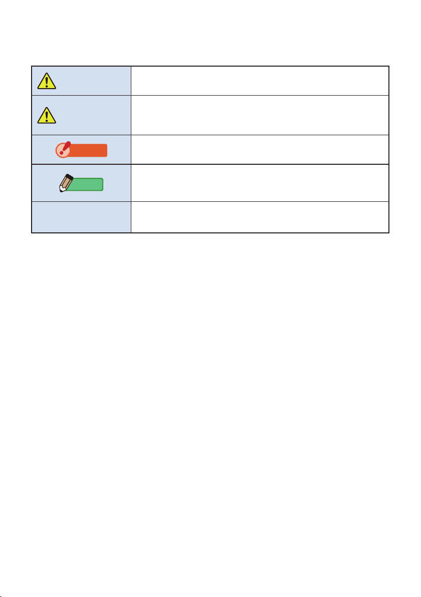
WARNING
CAUTION
NOTICE
NOTE
The WARNING symbol indicates the possibility of death or serious
injury if the product is not used properly.
The CAUTION symbol indicates the possibility of minor to moderate
personal injury or product damage if the product is not used properly.
The NOTICE symbol indicates cautions or restrictions when using the
product. Please read all notes to avoid errors in operation.
The reference symbol indicates additional information about the
controls or related functions.
Reading these is recommended.
The arrow indicates reference pages.
i
Page 4

WARNING
●
I
nfants or toddlers may accidentally wrap the strap around their neck, so
please place it in a location out of their reach. There is a danger of suffocation.
●
D
o not place batteries in open ames, attempt to short, disassemble or apply heat
to them, use unspecied batteries, or recharge them (except rechargeable batteries).
They may burst and cause res, serious injury, or damage to the environment.
●
Do not use the spectrometer in a place containing ammable or combustible
vapors. Otherwise, it may cause a re.
●
Exercise care not to drop uids on the spectrometer. Also, do not attempt
to insert metals into it. Doing so may cause a re or an electric shock. If any
uid drops on or a metal is inserted into the spectrometer, turn the power
switch OFF immediately, and remove the battery (or unplug the USB power
cable). Then, consult our Support Center for assistance.
●
Do not disassemble or modify this spectrometer. Doing so may cause a re
or an electric shock.
CAUTION
●
D
o not handle this product with wet hands, or leave it in the rain or in a location
where it may be splashed with water, submerged, or come into contact with moisture.
There is a danger of electric shock if the "Flash Light Cord (PC) Mode" is used.
This may also result in damage to the product.
●
Do not attempt to disassemble the product for modication or parts
replacement. It may affect measurement results or damage the meter.
●
Do not attempt to play the included CD-ROM using an audio CD player.
It may impair hearing or damage speakers and earphones.
●
G
ently tap the meter's LED panel when changing modes or making selections.
Using pointed pens or pencils may scratch the LCD screen or damage the product.
●
I
nfants or toddlers may accidentally grab the strap and swing the product, so please
place it in a location out of their reach, as the meter may be damaged by impacts.
●
Be careful that the neck strap does not come loose when carrying the
product, as the meter may be damaged when dropped.
●
This neck strap is made of polyester ber.
Please refrain from using the product if synthetic bers cause your skin to
become irritated, inamed or itchy in order to prevent worsening your symptoms.
●
Do not measure a bright object that emits light exceeding the measuring
range (wavelength and illuminance). They may damage the optical
components and result in inaccurate measurement.
●
Before removing or replacing the battery or USB cable, always turn the
power switch OFF. Otherwise, the spectrometer may fail.
●
Do not place the product on an unstable or tilted bench. Otherwise, it may
drop and you may be injured.
ii
Page 5

■
Polyvinyl Chloride (PVC) cable and cord notice
WARNING
Handling the cord on this product or cords associated with accessories sold
with this product will expose you to lead, a chemical known to the State of
California to cause cancer, and birth defects or other reproductive harm.
Wash hands after handling.
iii
Page 6

NOTICE
●
A protective sheet is attached to the LCD. Peel it off before use.
●
Although the LCD monitor is manufactured to very high standards, it is possible to
observe a few dead pixels on the screen. This is normal and not a malfunction of the
meter.
●
Do not use at altitudes above 2,000m (6,561 feet).
●
Our company shall not be liable for any data loss caused by, but not limited to, malicious
acts and control errors.
●
You can install the software on the included CD-ROM only when you agree with all
articles in the license agreement that comes with the CD-ROM.
●
Be sure not to drop the meter or subject it to sudden impacts, as the meter will be
damaged.
●
Do not store the meter in areas of high temperature of high humidity, as the meter will be
damaged.
●
Be careful not to transport the meter from cold to warm moist conditions as condensation
will form on the meter and may damage it.
●
If the meter is operated in temperatures below -10°C, the response of the LCD will
greatly slow down and the display may be difcult to view and read. This will not harm
the meter. Also, if the temperature exceeds 50°C, the liquid crystal display will darken
and become difcult to read, but when it returns to room temperature it will return to its
normal condition.
●
If the meter is left in direct sunlight, a vehicle, or near a heater, the unit's temperature will
rise and may result in damage. Please be careful when using the meter in these types of
locations.
●
If the meter is left where corrosive gases may be generated, the gases may affect the
product and may result in damage. Please be careful when using the meter in these
types of locations.
●
In case of disposing the meter, follow the rules of disposal in your area.
Maintenance Notes
●
Be careful not to let the Light Receptor become dusty, dirty, or scratched as this may
affect the precision of the measurement.
●
If the meter becomes dirty, wipe it with a dry, soft cloth. Never use organic solvents such
as thinner or benzine.
NOTE
●
For used batteries, dispose of them according to the rules of your area, or bring them to
a battery recycling shop near you.
●
Insulate plus and minus terminals with tape or other insulation material.
●
Do not remove the covering material of batteries.
●
Do not disassemble the batteries.
iv
Page 7
■
Intended Usage
The meter is designed for:
●
Measuring correlated color temperature, deviation, color rendering index (CRI),
illuminance, tristimulus value, chromaticity coordinates, dominant wavelength
and excitation purity of various lighting sources such as LEDs, organic EL's and
projectors.
●
Measuring automotive LED headlights and other types of lamps.
●
Measuring the illuminance of optical bio-reactions.
●
Controlling the illuminance and monitoring spectral distribution of light source for
indoor agriculture.
●
Evaluating the illuminance, color temperature, and color rendering index of road
lighting, indoor lighting, store lighting, and others.
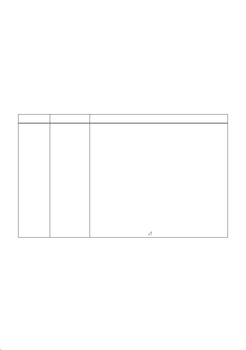
Main features of the C-7000
Model name Usage Features
C-7000
Industrial
applications
Monitoring and controlling illumination and color of light
sources for industrial and environmental applications.
●
Correlated color temperature (1,563K ~ 100,000K)
●
Illuminance measurement (1 lx ~ 200,000 lx)
●
Luminous exposure measurement (20 lx·s ~ 20,500 lx·s)
●
Displayed in accordance with usage
(1) Color temperature
(2) CRI measurements
(3) xy chromaticity diagrams (CIE1931 and CIE1964)
(4) u'v' chromaticity diagram (CIE1976)
(5) Spectrum display
(6) Spectral distribution graph display, graph display
enlargement function
(7) Illuminance/luminous exposure (ambient light/
ash light)
(8) Color deviation ( uv)
v
Page 8
■
Intended Users
The intended users of this product are the following.
●
People monitoring and quality control of LED, OLED, projector illumination, etc.
●
People monitoring and management of illumination during installation and use of
lamps used in museums, restaurants, work spaces, etc.
●
People controlling color and brightness of illumination used for indoor agriculture.
■
Restrictions
There are some cautions and restrictions regarding the use of this product.
Please read and understand the following before using the meter.
NOTE
●
The operation of this meter may change without prior notice due to specication changes
or other reasons. Therefore, the contents of this operating manual may differ from actual
operation of the meter. Please visit www.sekonic.com for the latest information.
●
Cautions regarding safety such as the Usage Precautions and the Safety Precautions
comply with the legal and industrial standards at the time of the making of this operating
manual. Therefore, the described contents may not comply with current precautions.
Please visit www.sekionic.com for the latest version of the instruction manual.
●
The product may contain printing material such as cautions related to safety and printing
errors as a supplement to the operating manual.
●
The contents of this operating manual may be reproduced for non-commercial purposes
and for personal use only. However, the reproduced material must contain the copyright
notice of our company.
●
The screens in this operating manual may differ from the actual displays of the meter you
are using. (Colors, letters, etc.)
vi
Page 9
■
Safety Precaution
For Proper Operation
Before using this product, please read this "Safety Precautions" for
proper operation.
WARNING
The WARNING symbol indicates the
possibility of death or serious injury if the
product is not used properly.
CAUTION
The CAUTION symbol indicates the
possibility of minor to moderate personal
injury or product damage if the product is
not used properly.
NOTICE
The NOTICE symbol indicates cautions
or restrictions when using the product.
Please read all notes to avoid errors in
operation.
General Safety Information
• Read the Operating Manual before use.
• Keep the Operating Manual on hand for reference at any
time.
• Stop using this product when there are any abnormalities.
• The modication or disassembly of this product is prohibited.
• Do not attempt to repair this product by yourself.
• This product is intended only for persons with expert
knowledge.
• Monitor children so that they do not touch this product.
• Use this product in a usage environment described in the
Operating Manual.
• This product is not waterproof.
WARNING
There is a danger of electrical shock when using high
voltage strobes.
Avoid contacting the terminals.
This product emits electromagnetic waves.
Do not bring this product close to persons with
pacemakers.
Do not use this product in an explosive atmosphere.
Use of devices emitting electromagnetic waves is
prohibited in hospitals.
CAUTION
• Check the material of the neck strap to see if there is any
risk of allergy.
• Be careful of sudden emission of lights from strobes.
NOTICE
• Do not leave this product on car dashboards in hot weather.
This may damage the product.
• Remove the batteries when this product is not in use for a
long period of time.
• When the desired performance is not achieved, stop using
this product and contact the service center.
Information for Users on Collection and
Disposal of Old Equipment
To protect environment, do not through this device
and batteries away with the normal household waste
at the end of those life, but bring them in at an
ofcial collection point of your country for recycling.
English
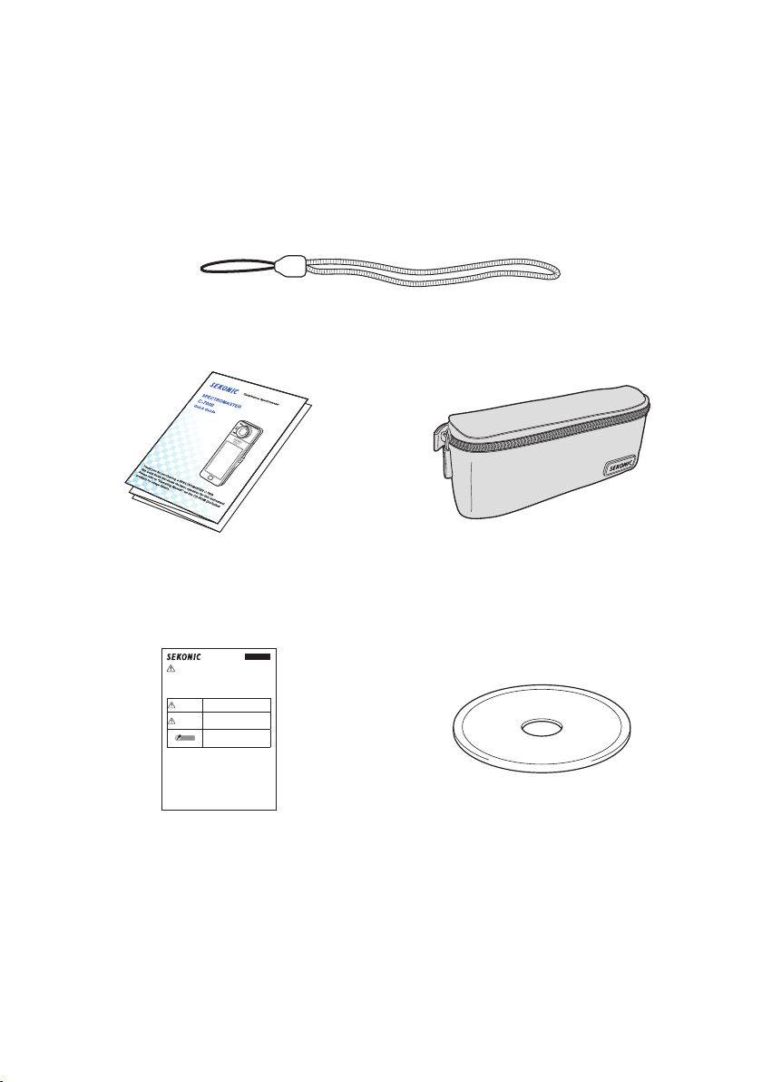
Accompanying Accessories
The following items are included with the SPECTROMASTER C-7000. Conrm if any
accessories are missing after unpacking.
If something is missing, contact the sales agent.
Batteries (size AA) and a USB cable are not included.
Neck Strap
Quick Guide Soft Case
Safety Precaution CD-ROM
(Operating Manual,
C-700/C-7000 Series Utility)
vii
Page 10

Table of Contents
Safety Precautions
■
Polyvinyl Chloride (PVC) cable and cord notice
■
Intended Usage
■
Intended Users
■
Restrictions
■
Accompanying Accessories
■
........................................................................................................................................
............................................................................................................................................
............................................................................................................................................
...................................................................................................................................................
...................................................................................................................
1. Parts Designations and Functions
1-1
Parts Designations
1-2
Parts Functions
2. Before Use
2-1
2-2
2-3
2-4
2-5
2-6
................................................................................................................................................
Attaching the Strap
Installing the Batteries
Power ON/OFF
Checking the Battery Capacity
Automatic Power OFF Function
Changing Batteries During Measurement
3. Basic Operation Methods
3-1
Basic Operation Flow
3-2
Screen and Operation
3-2-1
Basic Screen and Operation
3-2-2
Icon Operation
3-2-3
Input of Numbers/Characters
3-2-4
Locking and Unlocking the Screen
...................................................................................................................
.........................................................................................................................
..................................................................................................................
.............................................................................................................
.........................................................................................................................
..............................................................................................
...........................................................................................................
............................................................................................................
...........................................................................................................
................................................................................................
........................................................................................................................
..............................................................................................
............................................................................
........................................................................................
..........................................................................................
.........................................................................
.....................................................................................
i
iii
v
vi
vi
vii
1
1
2
3
3
4
5
9
10
11
12
12
14
14
18
19
21
4. Setting the Measuring Conditions
4-1
Selecting the Measuring Mode
4-1-1
Matching Measuring Mode with Light Sources
4-1-2
Selecting the Exposure Time (Ambient Modes Only)
4-1-3
Selecting the Shutter Speed (Flash Modes Only)
4-2
Customizing Measuring Displays
4-3
Selecting the Display Mode
4-3-1
Displaying in Text [Text] Mode
............................................................................................
.................................................................................................
.......................................................................................
................................................................
.....................................................
...........................................................
.......................................................................................
..........................................................................................
viii
22
22
22
24
25
27
28
32
Page 11

4-3-2
Displaying in Spectrum Graph [Spectrum] Mode
4-3-3
Displaying in Spectrum Comparison
[Spectrum Comp.] Mode
4-3-4
Displaying in Color Rendering Index [CRI] Mode
4-3-5
Displaying in CIE1931 (CIE1964) [CIE1931 (CIE1964)] Mode
4-3-6
Displaying in CIE1931 (CIE1964) Comparison
[CIE1931 (CIE1964) Comp.] Mode
4-3-7
Displaying in CIE1976 [CIE1976] Mode
4-3-8
Displaying in CIE1976 Comparison
[CIE1976 Comp.] Mode
4-3-9
Displaying Setting [Setting] Screen
.......................................................................................................
....................................................................................
.........................................................................
........................................................................................................
.................................................................................
.........................................................
.........................................................
.................................
35
38
43
46
48
52
54
58
5. Measuring Light Sources [Measurement Screen]
5-1
Measurement Method
5-1-1
Balancing Color Temperatures of Light Sources
5-2
Measurement in Ambient Light Mode
5-3
Measurement in Cordless Flash Mode
5-4
Measurement in Cord (PC) Flash Mode
5-5
Monitor Function (in Ambient Light Mode only)
5-6
When [Over] or [Under] is Displayed
5-6-1
Display of [Over] or [Under]
5-6-2
Changing the Light Range
6. Measurement Tool [Tool Box] Screen
6-1
Setting Preset Contents [Preset Selection] Screen
6-2
Using the Memory Function
6-2-1
Naming Measurement Values Being Memorized [Memory Title] Screen
6-2-2
Recalling Measurement Results [Memory Recall] Screen
6-2-3
Renaming Memory Title [Memory Rename] Screen
6-2-4
Deleting Memorized Value [Memory Clear] Screen
6-3
Selecting Exposure Time [Exposure Time] Screen
6-4
Setting the Shutter Speed [Shutter Speed] Screen
...........................................................................................................
.............................................................
................................................................................
..............................................................................
...........................................................................
...............................................................
.................................................................................
.................................................................................................
...................................................................................................
...........................................................................
.....................................................
.................................................................................................
.....................................................
....................................................
...................................................
................................................
.................
.........................................
....................................................
60
60
60
61
65
69
73
77
77
78
79
80
83
84
88
93
96
101
103
7. Meter Settings [Setting] Screen
7-1
7-1-1
7-2
Setting Items
Item List
Customize
.........................................................................................................................
..................................................................................................................................
..............................................................................................................................
.......................................................................................
ix
105
105
107
108
Page 12

7-2-1
Item Specications
7-2-2
Selecting the Unit of Illuminance
7-2-3
Selecting the Spectrum Y-axis Scale
7-2-4
Selecting the Auto Power Off Time
7-2-5
Selecting the Backlight Brightness
7-2-6
Selecting the Auto Dimmer Time
7-2-7
Reset Customized Items
7-3
Preset Editing
7-3-1
Displaying the Preset Selection List
7-3-2
Setting the Present Name
7-3-3
Setting the Tcp
7-3-4
Setting the ⊿uv
7-3-5
Setting the Tristimulus Value Y
7-3-6
Setting the λp
7-3-7
Setting the CRI
7-3-8
Setting the value of CRI
7-3-9
Setting the PPFD (Photosynthetic photon ux density)
7-4
Dark Calibration
7-5
Product Information Display
7-6
Regulation Display
...............................................................................................................
......................................................................................
...................................................................................
...................................................................................
......................................................................................
....................................................................................................
.......................................................................................................................
.................................................................................
..................................................................................................
......................................................................................................................
...................................................................................................................
.........................................................................................
........................................................................................................................
.....................................................................................................................
......................................................................................................
....................................................................................................................
...............................................................................................
...............................................................................................................
...............................................................................
...............................................
109
110
112
115
117
119
121
122
128
130
132
134
136
138
140
142
144
146
149
151
8. Hardware Setting Screen
8-1
Adjust Touch Panel
8-2
Edit User Information
8-3
Field of View
8-4
Factory Setting
9. Appendix
................................................................................................................................................
9-1
Glossary
9-2
Specications
9-3
Legal Requirement
10. Optional Accessories
11. Troubleshooting
..........................................................................................................................
.....................................................................................................................
.................................................................................................................................
........................................................................................................................
..............................................................................................................
...................................................................................................................
...............................................................................................................................
..........................................................................................................
..............................................................................................................
..........................................................................................................
x
152
154
157
159
161
164
164
166
169
170
171
Page 13

xi
Page 14
1. Parts Designations and Functions
1.
Parts Designations and Functions
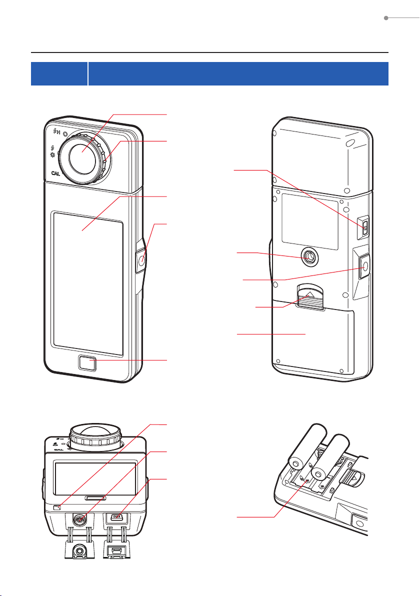
1-1 Parts Designations
Front View
Light Receptor
1
Light Selection Ring
2
Power Button
3
Display Panel
4
Measuring Button
5
Tripod Socket
0
Memory Button
7
Battery Cover Latch
8
Rear View
Bottom View
Battery Cover
9
Menu Button
6
Strap Eyelet
c
Sync Terminal
b
USB Connector
a
Battery
d
Compartment
1
Battery Compartment Section
Page 15
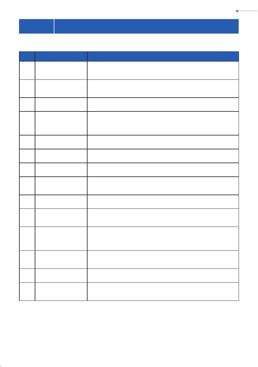
1-2 Parts Functions
The following table lists the functions of each part.
No. Part Name Functions
1. Parts Designations and Functions
Light Receptor
1
Light Selection
2
Ring
Power Button
3
Display Panel
4
Measuring Button
5
Menu Button
6
Memory Button
7
Battery Cover
8
Latch
Battery Cover
9
Tripod Socket
0
USB Connector
a
Point light receptor directly at light source during reading. Head
rotates 270 degrees to aid reading.
Rotate to select dark calibration, normal measuring range or high
range for ash light.
Press to turn ON/OFF.
Displays the setting screens and measurement screens. The builtin touch panel function enables setting, selection or operation by
touching the displayed screens. (P18)
Press for measurement.
Press to shift display to Display Mode Selection screen.
Press after measuring to record the measured data.
Latch for the battery cover.
Secures the batteries.
Female mounting threads (1/4-20) for hands free mounting on
tripods.
The USB connector for connecting to the PC with the installed
application and USB bus power.
USB terminal: Mini-B-5pin
b
c
d
Sync Terminal
Strap Eyelet
Battery
Compartment
Accepts an optional synchro cord when using meter in Cord (PC)
Flash Mode.
Used to attach the included strap.
Holds two AA size batteries. Insert the batteries in the correct
direction.
2
Page 16
2. Before Use
2.
Before Use
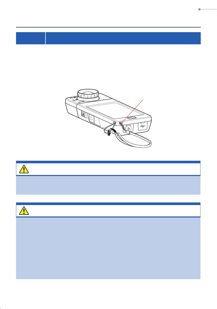
2-1 Attaching the Strap
Pass the strap (included) through the outer hole of the Strap
1.
Eyelet c.
Pass the opposite end of the strap through the loop at the end of
2.
the strap.
Strap Eyelet
c
WARNING
Infants or toddlers may accidentally wrap the strap around their neck, so
please place it in a location out of their reach. There is a danger of suffocation.
CAUTION
●
Infants or toddlers may accidentally grab the strap and swing the product,
so please place it in a location out of their reach, as the meter may be
damaged by impacts.
●
Be careful that the neck strap does not come loose when carrying the
product, as the meter may be damaged when dropped.
●
This neck strap is made of polyester ber.
Please refrain from using the product if synthetic bers cause your skin
to become irritated, inamed or itchy in order to prevent worsening your
symptoms.
3
Page 17
2. Before Use
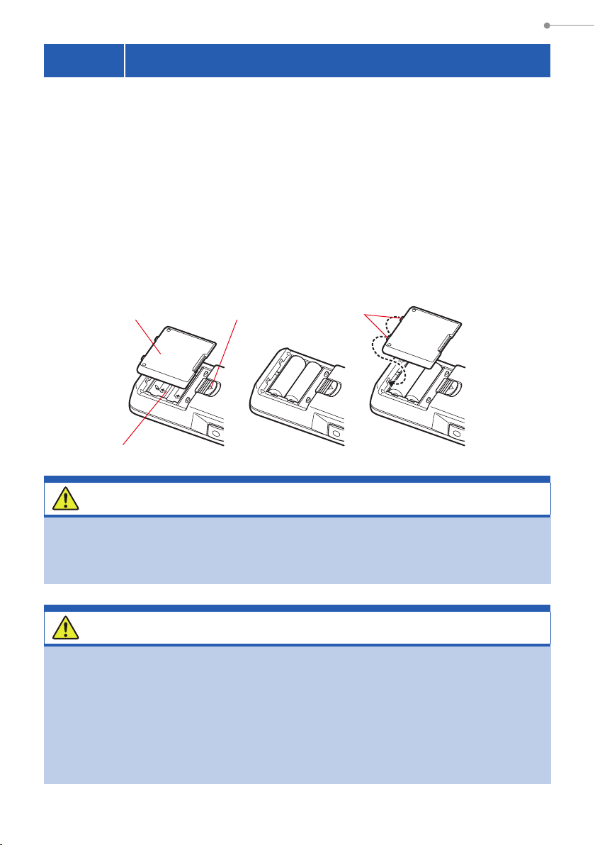
2-2 Installing the Batteries
Prepare two AA batteries.
1.
Slide the Battery Cover Latch 8 in the direction of the arrow and
2.
remove the Battery Cover 9.
Insert the batteries according to the "+" and "-" symbols in the
3.
Battery Compartment d.
* As shown in the diagram below, please note both positive sides of the batteries are
facing in the same direction.
While lining up the two tabs on the Battery Cover 9, press the
4.
Battery Cover 9 back into place from above.
Battery Cover
Battery Compartment
Battery Cover Latch
9
d
8
Tabs
WARNING
Do not place batteries in open ames, attempt to short, disassemble, apply
heat to, or recharge them (except rechargeable batteries). They may burst and
cause res, serious injury, or damage to the environment.
CAUTION
●
Please insert the batteries minus "-" side rst.
When removing the batteries, remove them plus "+" side rst.
●
Do not use batteries with any other rating than the one specied.
Also, do not mix old and new batteries.
●
lf the meter will not be used for an extended period of time,
it is recommended to remove the batteries to avoid possible damage caused
by battery leaking.
4
Page 18
2-3 Power ON/OFF
2. Before Use
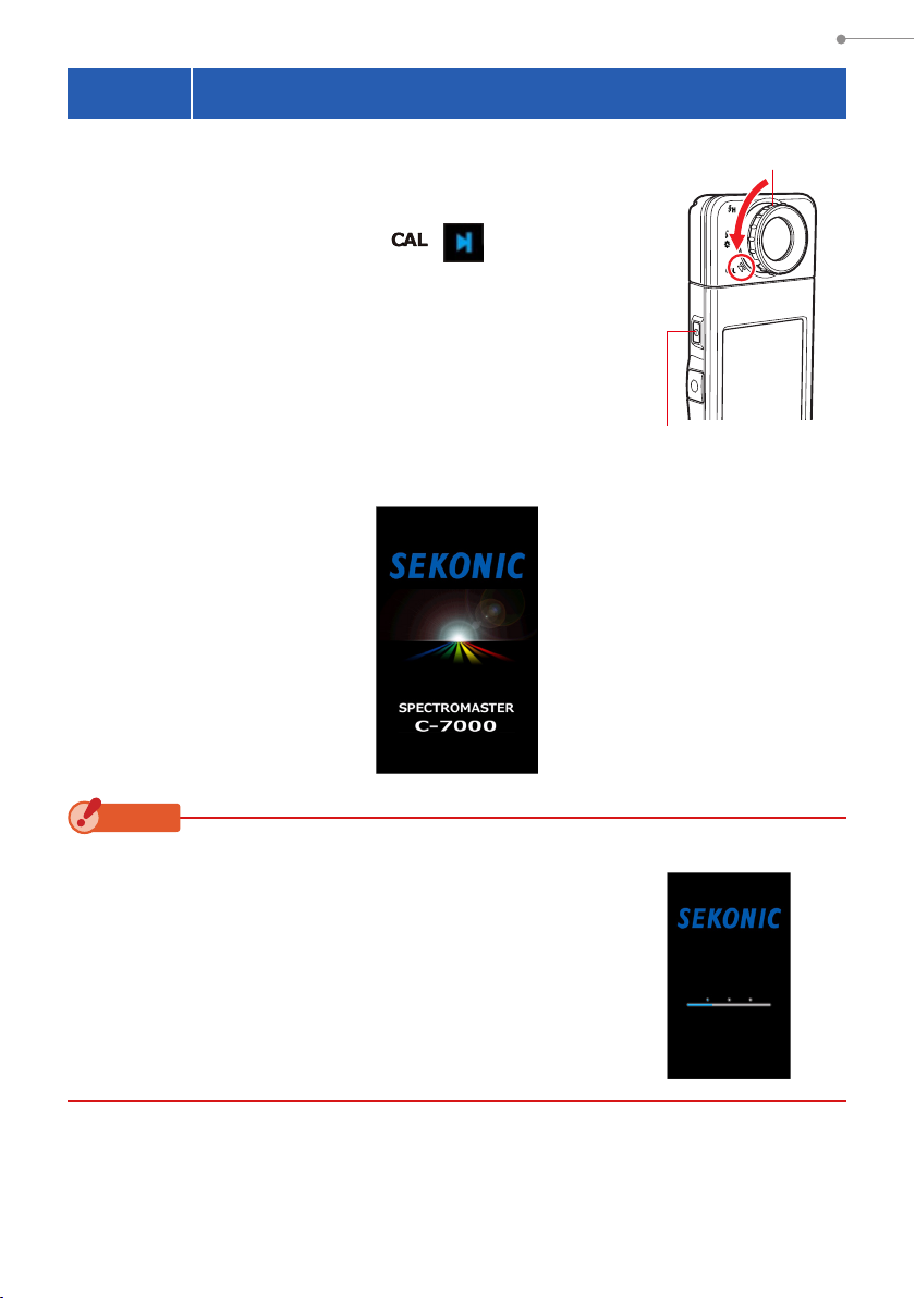
Power ON
Turn the Light Selection Ring 2 to set to the
1.
dark calibration position ( ).
Press the Power Button 3.
2.
The meter will turn on and the Opening screen will be
displayed (for 2 seconds).
C-7000 Opening Screen
Light Selection Ring
Power Button
3
2
NOTICE
●
The blue lettered "SEKONIC" logo screen is displayed
after battery replacement and 24 hours after power OFF.
●
Movement of the blue status bar indicates that the meter
is checking its memory and preparing to operate. Do
not turn the power OFF. Otherwise, the meter may be
damaged.
5
Logo Screen
Page 19
2. Before Use
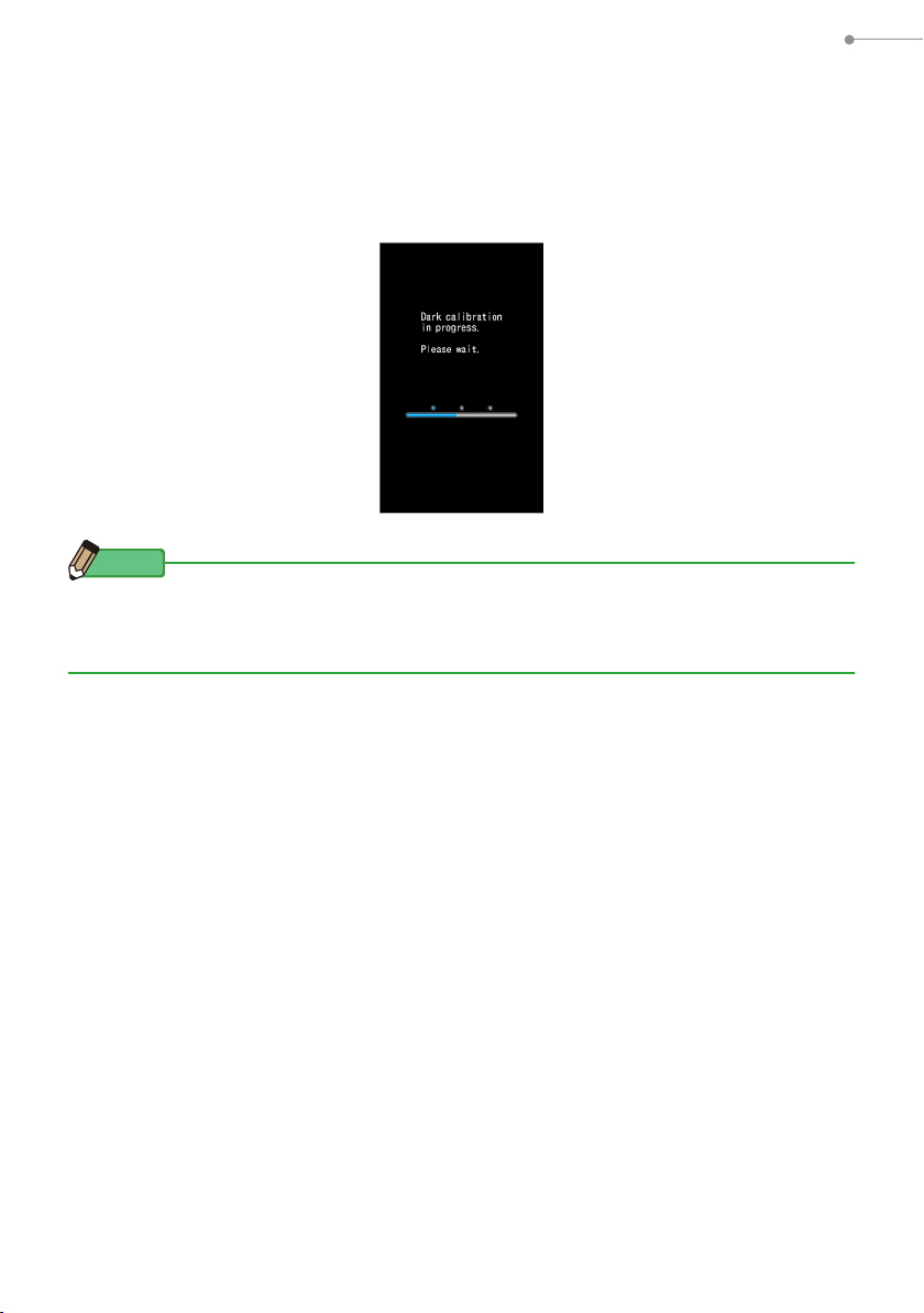
Dark calibration.
3.
The C-7000 measuring system must be calibrated before use. Turn Light Selection
Ring to calibration indication. "Dark calibration in progress. Please wait" and the
status bar will appear while calibrating. The Display Mode Selection screen will
appear when operational.
Dark Calibration
Process Screen
NOTE
Dark calibration is performed when new batteries are used, 24 hours passed since last use
or there is a big change in temperature between turning power OFF and ON.
Except the cases above, dark calibration after power ON is skipped.
6
Page 20
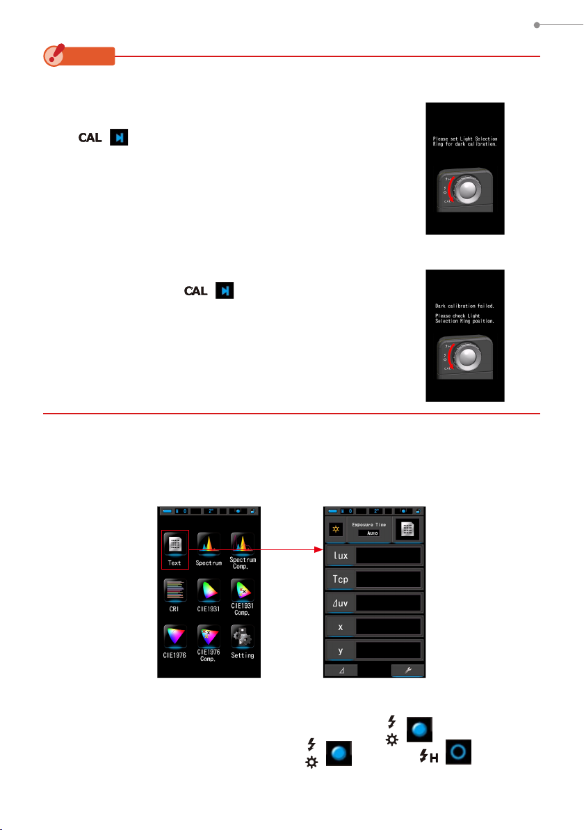
NOTICE
●
When the Light Selection Ring 2 is not set to the dark
calibration position, the message "Please set Light
Selection Ring for dark calibration." is displayed. Set the
Light Selection Ring 2 to the dark calibration position
( ) to calibrate the system.
●
If dark calibration is not successful, "Dark calibration
failed. Please check Light Selection Ring position." is
displayed. Set the Light Selection Ring 2 to the dark
calibration position ( ) to calibrate the system.
2. Before Use
Dark Calibration Position
Conrmation Screen
Dark Calibration
Conrmation Screen
Touch the icon to be displayed on the Display Mode Selection
4.
screen.
The display will switch to the selected measurement screen.
Display Mode Selection Screen Measuring Screen
Press the Measuring Button 5 to measure.
5.
Turn the Light Selection Ring 2 to select the range.
When measuring ambient light, make sure to select Range L ( ).
When measuring ash units, select Range L ( ) or Range H ( )
depending on the brightness of of the ash. (P77, P78)
7
Page 21
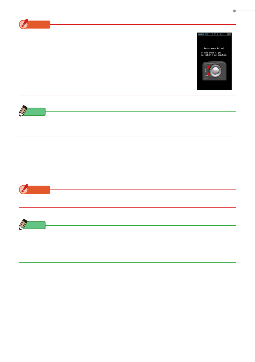
NOTICE
When the Measuring Button 5 is pressed at the dark calibration
position, the message "Measurement failed. Please check Light
Selection Ring position." is displayed. Turn the Light Selection Ring
to select the range.
2
NOTE
Measurement and display will take longer in light levels below 30lx. The LCD illumination
will normally switch off during measurement to avoid inuence to measurement.
Power OFF
Press and hold the Power Button 3 for 1 second or longer.
1.
The meter will turn OFF.
2. Before Use
NOTICE
Please wait 3 seconds between repeated power on and power off sessions.
NOTE
●
If the LCD screen shows no display, check if the batteries are installed properly (Pos/Neg
positioning) and have enough capacity.
●
All settings and measurements made during use are saved in memory even after the
meter is powered off.
8
Page 22
2. Before Use
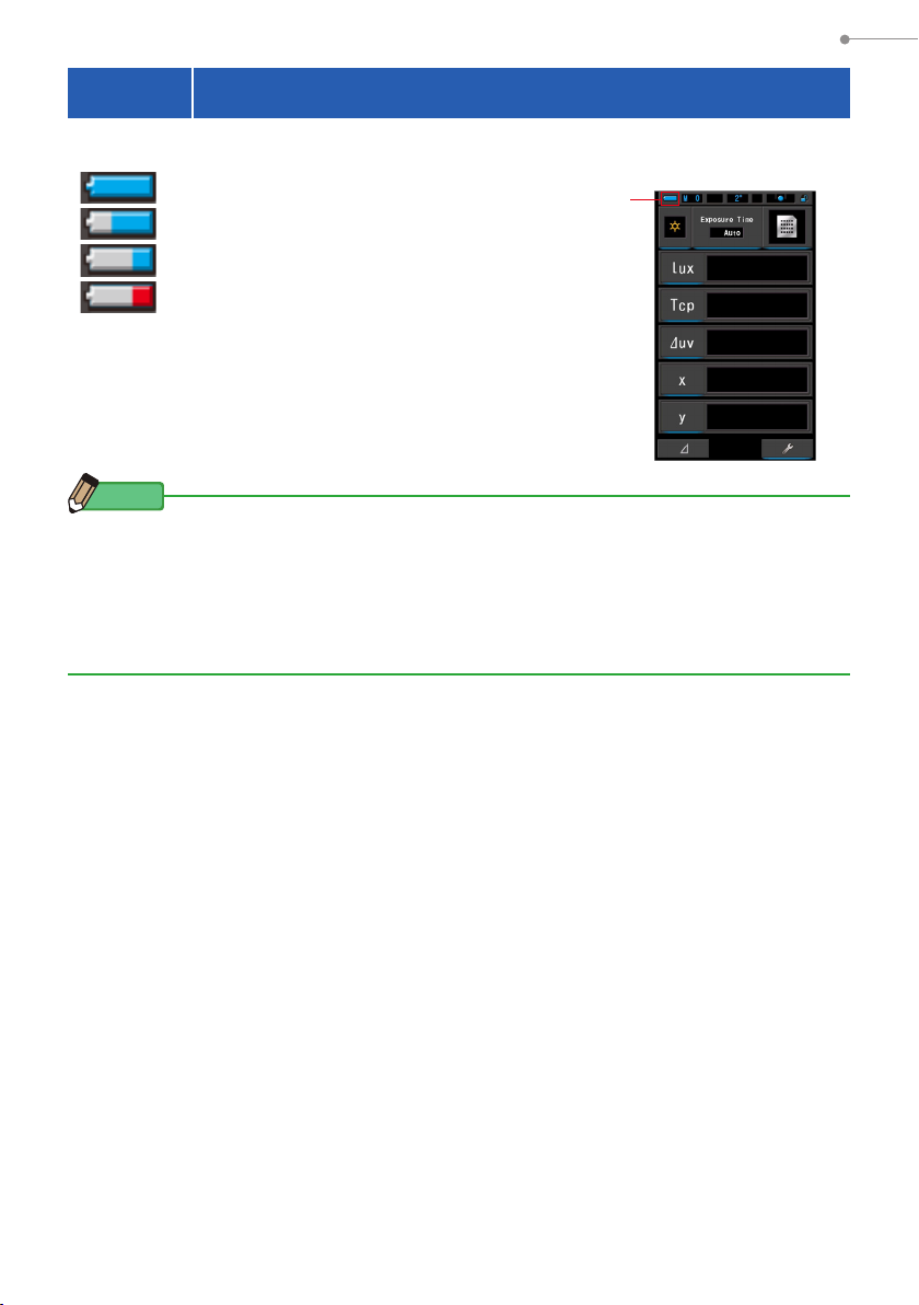
2-4 Checking the Battery Capacity
When the power is turned ON, the LCD screen will show the battery capacity indicator.
Sufcient battery life remaining.
Adequate battery life remaining.
Battery capacity
indicator
Have a spare battery ready.
Replace the battery immediately.
NOTE
●
When battery power is low and the meter is turned ON, the LCD screen will appear and
then turn off immediately. This is an indication that the batteries are depleted and should
be replaced immediately.
Having spare batteries on hand is recommended.
●
When the meter is continuously used at room temperature, the battery life should last 8
hours (based on Sekonic testing methods).
9
Page 23
2. Before Use
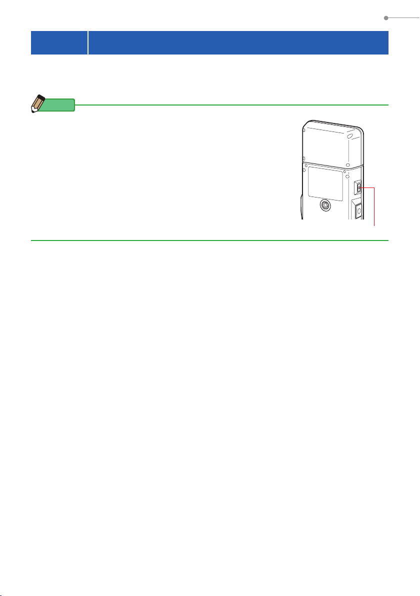
2-5 Automatic Power OFF Function
To save battery capacity, the meter will automatically turn off 5 minutes (factory
setting) after the last button is pressed.
NOTE
●
All measurements, settings and indications are saved in memory
even after the meter has automatically turned off. When the
power is turned ON, they will be displayed again.
●
The automatic power off time setting can be selected according
to your needs in the settings. (P115)
●
If, while in transport, the Power Button 3 is inadvertently and
continually pressed in, the meter will turn ON for about 1 minute
and then turn automatically turn OFF to save battery power.
Power Button
3
10
Page 24

2. Before Use
2-6 Changing Batteries During Measurement
●
Please make sure the power is OFF when replacing batteries. If left ON, the meter
circuit could be damaged and measurements taken during the last operation will not be
saved.
●
If an unexpected display appears on the LCD during battery replacement or
measurement, ie. settings other than selected, or if the meter does not respond when
a button is pressed, remove the batteries, wait at least 10 seconds, and then re-install
them.
11
Page 25
3. Basic Operation Methods
3.
Basic Operation Methods
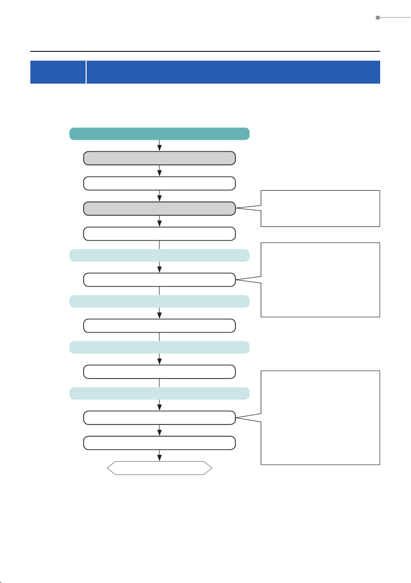
3-1 Basic Operation Flow
The basic operations and screens are as follows. Measurements and measurement
changes are operated from the Measurement screen.
Power ON
Opening Screen
Language Selection (for rst time only)
Make sure the Light Selection
Dark Calibration
Display Mode Selection Screen
[Setting] icon
Setting Screen
[Close] Button
Display Mode Selection Screen
Ring 2 is set to the dark
calibration position.
The user sets the functions
depending on the intention.
•Customize (the meter for
your preference)
•Edit a preset
•Dark calibration
•Display the information
Any [Display Mode] Icon
Measurement Screen
[Tool Box] Icon
Tool Box Screen
Measurement Screen
To the next page
12
The user sets the measurement
functions depending on the
intention.
•Preset Selection
•Memory Title Setting
•Exposure Time
•Shutter Speed
•Memory Management
(Recall, Rename, Clear)
Page 26
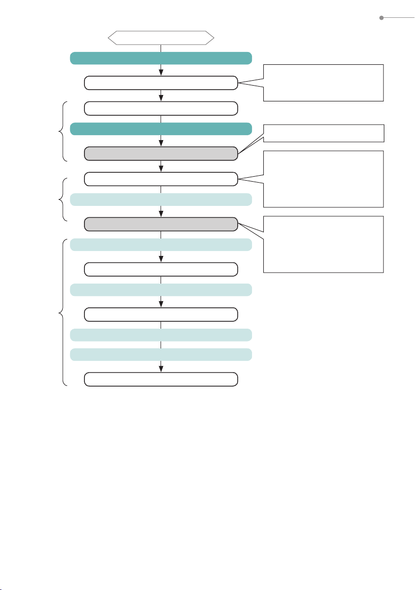
From the previous page
[Measuring Mode] Icon
Measuring Mode Selection Screen
Measurement Screen
3. Basic Operation Methods
Select the measuring mode.
Ambient Light, Flash Light
(Cordless, Cord)
Measuring
Memory
Stored
Value
Measuring Icon
Measuring Screen
Measurement Screen
Memory Button
Measurement Screen
[Tool Box] Icon
Tool Box Screen
[Memory Management] Button
Memory Management Screen
Memory Recall, Rename or Clear Selection
[Close] Button
Memory Management Screen
The LCD dims when measuring.
When measurement is
complete, the LCD returns to the
previous user set brightness,
and the measurement results
are displayed.
Pressing the Memory Button
stores the displayed data with
memory title (set in Tool Box in
advance) and "M1" appears in
the Status Bar.
13
Page 27
3. Basic Operation Methods
3-2 Screen and Operation
3-2-1 Basic Screen and Operation
The touch-screen display enables selecting Display Modes and settings with the
touchofyournger.
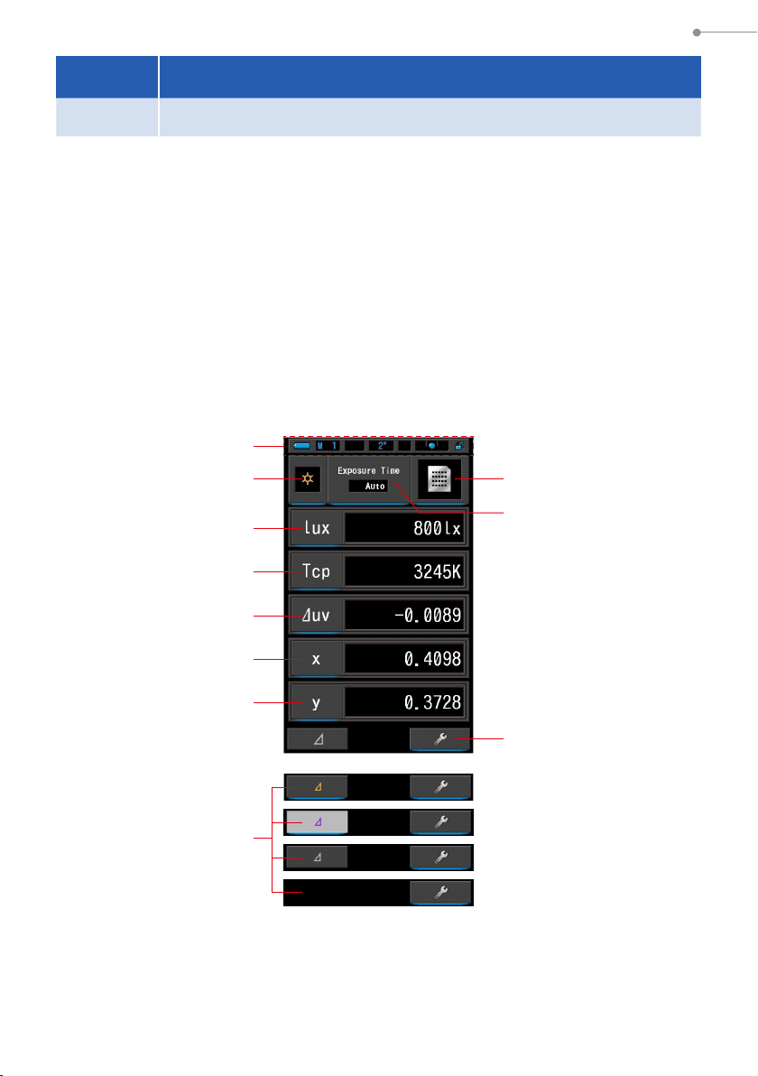
Measurement Screen
The Measurement screen is displayed (for 2 seconds) after the power is turned ON, and
the dark calibration is made.
When the dark calibration is complete, the Display Mode Selection screen is displayed.
Select the desired display mode and the selected measurement screen is displayed.
Press the Measuring Button to make a measurement after setting the measuring mode
(ambientorashlight)andrelevantsettingsinToolBox.
* Pressing the Menu Button 6 returns the meter to the Display Mode Selection screen.
Measuring Screen in Text Mode
1
2 3
4
5
6
7
8
10
* The display changes depending on the set measuring mode.
* For this description, all icons and menus are displayed.
14
11
9
Page 28
Item List
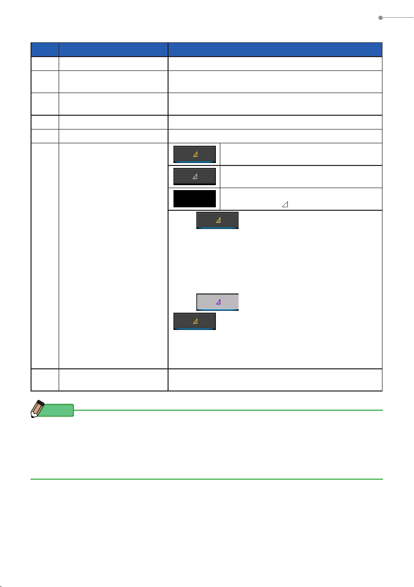
No. Part Name Description
Status Bar
1
[Measuring Mode] Icon
2
[Display Mode] Icon
3
[Display Item] Indication
4 ~ 8
[Tool Box] Icon
9
[Delta] Icon
(in Ambient Light Mode
10
only)
[Exposure Time]
11
Indication
Displays the setting contents. (P16)
Displays the measuring mode. (P22)
Switches to the Measuring Mode Selection screen.
Displays the display mode. (P28) Switches to the
Display Mode Selection screen.
Switches to the Item Selection screen. (P27)
Switches to the Tool Box screen. (P79)
Displays when Monitor Function can be
performed.
When there is no reference preset value,
the icon is disabled.
When Monitor Function cannot be
performed, the ( ) icon is not displayed.
When is touched, Monitor Function is
activated. The preset value is shown in yellow letter when
this delta icon is displayed. When holding the Measuring
Button 5, the value differences of the preset value and
the current reading being measured will be displayed. (The
preset value is a value that has been preset.) When the
Measuring Button 5 is released, the display will revert to
the preset value.
When is touched, the icon returns to
and the values measured last are displayed.
Monitor Function is cancelled when the power is turned
OFF.
Note: When the Monitor Function icon is displayed, the
Memory Button 7 is disabled.
Switches to the Exposure Time Selection screen.
(P24)
3. Basic Operation Methods
NOTE
When values are outside the display or measurement range, [Under] or [Over] is displayed.
Under: Displayed if value is lower than measurement range (too dark) or color temperature
value Is too low.
Over: Displayed if value is higher than measurement range (too bright) or color
temperature value is too high.
15
Page 29
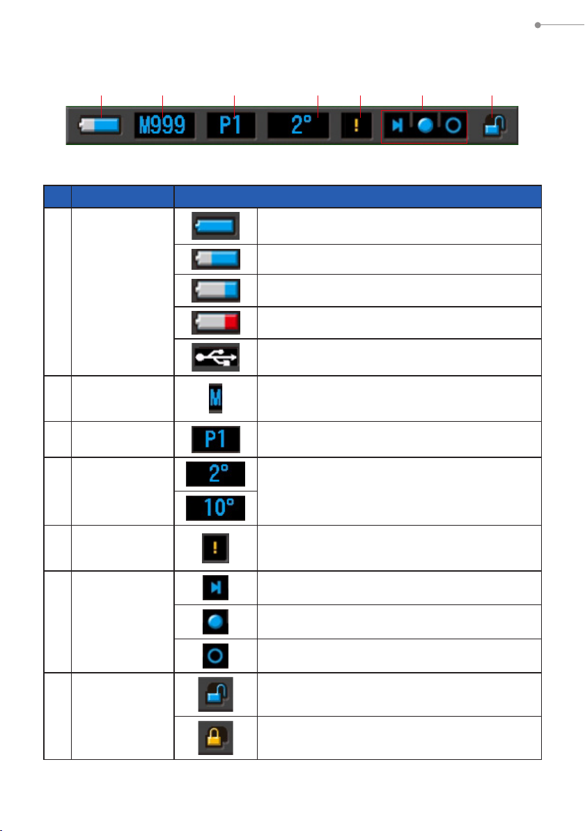
Status Bar
1 2 3 4 5 6 7
For this description, all icons and menus are displayed.
*
No. Part Name Description
Sufcientbatteryliferemaining.
Adequate battery life remaining.
3. Basic Operation Methods
Battery Capacity
1
Indicator
Memory Count
2
Preset Selection
3
Field of view
4
Temperature
Fluctuation
5
Warning
Light Selection
Ring Status
6
Indicator
Have a spare battery ready.
Replace the battery immediately.
Appears when powered by USB.
Displays the number of measured data stored in memory.
The number in memory is displayed until 999 to the
right of the mark.
Displays the preset number when a preset is selected.
Displays the viewing angle (2° or 10°) that was set
when hardware was set.
When the mark appears, the temperature is
uctuating,andaccuratemeasurementmaynotbe
possible. Please perform dark calibration.
Appears when the Light Selection Ring 2 is selected
by the dark calibration position.
Appears when the Light Selection Ring 2 has range
"L" selected.
Appears when the Light Selection Ring 2 has range
"H" selected.
Key Lock Status
7
Indicator
Appears when the screen is unlocked.
Appears when the screen is locked. When the screen
is locked, touch panel operations are disabled.
16
Page 30
3. Basic Operation Methods
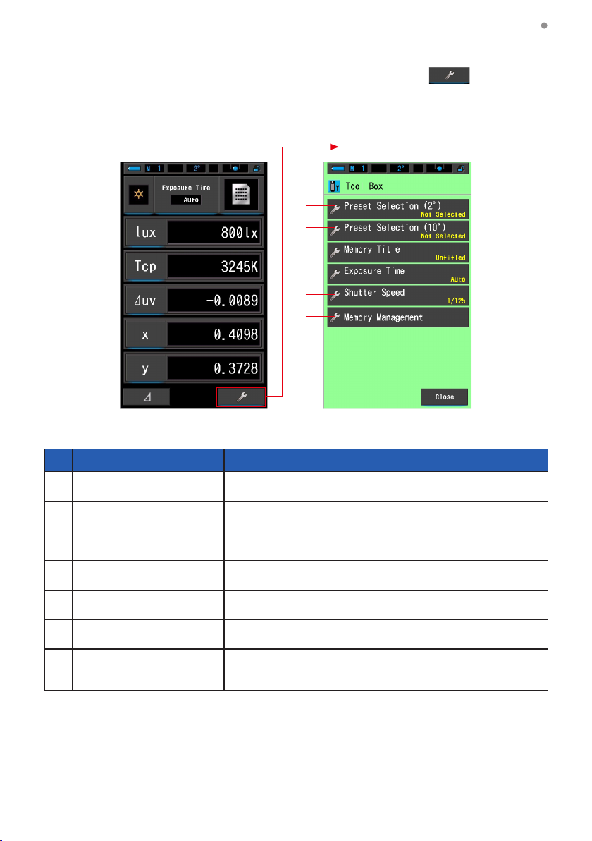
Tool Box Screen
The following setting can be performed after touching the [Tool Box ( )] icon on the
measuring screen.
* All icons are displayed for explanatory purposes for the Tool Box screen. It is not the
default.
Measuring Screen
in Text Mode
Tool Box Screen
1
2
3
4
5
6
7
[Tool Box: Item List]
No. Part Name Description
Preset Selection (2°)
1
Preset Selection (10°)
2
Memory Title
3
Exposure Time
4
Shutter Speed
5
Memory Management
6
[Close] Button
7
Switches to the Preset Selection screen. (P80)
Switches to the Preset Selection screen. (P80)
Switches to the Memory Title Input screen. (P84)
Switches to the Exposure Time screen. (P101)
Switches to the Shutter Speed screen. (P103)
Switches to the Memory Management screen. (P88)
Closes the Tool Box screen and returns to the Measurement
screen.
17
Page 31

3-2-2 Icon Operation
Touch Operation
Touch the icons on screen to perform various operations.
(Ex.) Measuring Screen in Text Mode
Touch-enabled Icons
A blue illumination under icons indicates which icons are operational.
Touch-enabled Icons Touch-disabled Icons
3. Basic Operation Methods
Slide Operation
Slideyourngertipupordownoveravaluetochangethevalueamount.
Slidingyourngeroverscrollbarprovidesfastnavigationoflargemenus.
(Ex.) Shutter Speed Selection Screen
Scroll Selection
Slideangerup
or down on the
setting value areas
to change setting
values.
One Step Icon
Touch the Up or Down icon
to advance one position.
* Blue bar indicates the value selected.
18
Top Icon
Touch to advance to
the lowest value.
Scroll Bar
Touch and slide up or
down to scroll settings.
Bottom Icon
Touch to advance to
the highest value.
Page 32

3-2-3 Input of Numbers/Characters
You can input numbers and characters.
Numeric Number Input Screen
(Ex.) Display of deviation uv
2 3
1
3. Basic Operation Methods
4 5
Numeric Number Method
No. Key Description
0-9, +/-, period
1
Delete
2
← →
3
OK
4
Cancel
5
Enters a numeric value, plus or minus sign, and a period. When touched,
the entry is displayed at the top of the screen.
Deletes input value at cursor position.
Moves input position.
Conrmsinputvalueandreturnstopreviousscreen.
Cancels input value and returns to previous screen.
19
Page 33

3. Basic Operation Methods
Character Input Screen
Figure Input Screen Upper Case Input Screen Lower Case Input Screen
8
0
a a ab b
Keypad (Upper Case Input Screen) Keypad (Lower Case Input Screen)
9 9 9
8
0
66
8
0
6
b
(Figures)
7
(Upper Case Letters)
7
(Lower Case Letters)
7
7 7
a a0 08 8b b9 9
Input Method of Characters and Numbers
No. Key Description
6
7
8
9
0
a
b
6 6
1/A/a
0-9, ABC,
abc, hyphen,
period
Delete
← →
Keypad
OK
Cancel
Shifts between numbers/upper case letters/lower case letters.
Value displayed on screen when key touched.
Repeated touching of the same button for alphabet (ABC/abc) will
change the alphabet character in order.
Deletes the character at the cursored position.
Moves input position.
Shifts between Standard Keypad and Qwerty Keypad.
Conrmsinputvalueandreturnstopreviousscreen.
Cancels inputting and returns to previous screen.
20
Page 34

3-2-4 Locking and Unlocking the Screen
You can lock the screen to prevent
misoperation.
When the screen is locked, touch operation is
disabled.
However, the Memory Button 7, Measuring
Button 5, and Power Button 3 are still
operational.
The screen will stay locked even when power
is turned OFF and ON.
3. Basic Operation Methods
Power
Button
3
Memory
Button
7
Measuring Button
To Lock
In any measuring mode, press and hold the Menu
Button 6 to see the Locked icon [ ] appear at
the upper right corner of the LCD screen.
Function Icons cannot be operated while the
screen is locked.
The Locked icon [ ] will appear for
approximately 1 second at the center of the screen
when function Icons are touched or MENU button
is pressed.
6
To Unlock
Press and hold the MENU Button 6 to see Unlocked icon [ ] appear at the
top of the LCD screen.
Locked Screen
[Locked] Icon
Unlocked Screen
5
Menu Button
[Unlocked]
Icon
6
21
Page 35

4. Setting the Measuring Conditions
4.
Setting the Measuring Conditions
4-1 Selecting the Measuring Mode
4-1-1 Matching Measuring Mode with Light Sources
Select the Measuring Mode to use.
NOTICE
When changing the measuring mode setting, the measurement data will be erased.
Measuring Mode Selection Screen
1
2
3
No. Measuring Mode Icon Description
Ambient Light Mode
1
Cordless Flash Mode
2
Cord (PC) Flash Mode
3
Measures continuous light such as sunlight, tungsten,
uorescent, and LED lights. (P61)
Detects ash color temperature without meter-ash
connection after Measuring Button pressed to arm
meter (for 90 seconds) and ash red separately.
Measure using a ash during the wait time. (P65)
Detects ash color temperature with PC (synchro)
cord meter-ash connection. (P69)
22
Page 36

4. Setting the Measuring Conditions
Operation
Touch the [Measuring Mode] icon in the upper left corner of the screen.
1.
The Measuring Mode Selection screen will be displayed.
Measuring Screen
in Text Mode
[Measuring
Mode] Icon
Touch an icon to select the measuring mode.
2.
Select the desired measuring mode.
Touch the [OK] button.
3.
Conrms the settings, and returns to the previous Measurement screen.
Touch [Cancel] to return to the previous measurement screen without setting.
Measuring Mode
Selection Screen
Measuring Mode
Selection Screen
Measuring Screen
in Text Mode
[Cancel]
Button
[OK] Button
Ex.) Ambient Light Mode→Cordless Mode
NOTE
●
Ambient light includes continuous light sources such as natural light (sunlight),
tungsten lamps, uorescent lamps, LED lights, etc.
●
Flash light includes brief and intense burst of light sources such as electronic
ash units or ash bulbs.
23
Page 37

4. Setting the Measuring Conditions
4-1-2
Selecting the Exposure Time (Ambient Modes Only)
Set a Exposure Time for ambient measurement.
Operation
T
ouch the [Exposure Time] indication on the Measurement screen.
1.
Touch the [Auto], [0.1 sec] or [1.0 sec] button.
Measuring Screen Exposure Time Screen
Touch the [OK] button.
2.
Conrms the settings, and returns to the previous Measurement screen.
Touch [Cancel] to return to the previous measurement screen without setting.
The selected
button will
be displayed
encircled in
blue.
[OK]
Button
[Cancel]
Button
Exposure time is set.
NOTE
In Auto mode, the C-7000 automatically selects among 15 measuring times,
determined by the illumination available, to achieve a proper result in a convenient way.
Two xed reading times are available to enable exact comparison of multiple
measurements.
When measuring high illuminance levels, set the Exposure Time to 0.1 sec.
When taking measurements in low Illuminance, set the Exposure time for 1.0 sec.
NOTICE
0.1 sec and 1.0 sec may not cover some measurement range of illumination
and [OVER] or [UNDER] appears. In this case, set Exposure time to "Auto".
24
Page 38

4. Setting the Measuring Conditions
4-1-3 Selecting the Shutter Speed (Flash Modes Only)
Set a shutter speed that is appropriate for the intended ash-ambient measurement.
Operation
Touch the [Shutter Speed] indication.
1.
Measuring Screen in Text Mode
Text Mode in
Cordless Mode
Select the desired shutter speed.
2.
Shutter Speed Screen
[Shutter Speed 1/125]
[Cancel]
Button
[OK] Button
Touch the [OK] button.
3.
Conrms the settings, and returns to the previous Measurement screen.
Touch [Cancel] to return to the previous measurement screen without setting speed.
[Shutter Speed 1/60]
The shutter speed is set.
25
Page 39

4. Setting the Measuring Conditions
NOTE
Shutter Speed Options
1 Step
1s
1/2
1/4
1/8
1/15
1/30
1/60
1/125
1/250
1/500
NOTICE
●
When measuring ash-light color in high ambient light conditions (580
or higher), select a shutter speed of 1/250 or 1/500 sec to reduce or
eliminate the inuence of the ambient light in the measurement. Using
slower shutter speeds will include ambient light color in the measurement.
●
Measuring data will be erased when the shutter speed setting is changed.
lx·s
26
Page 40

4. Setting the Measuring Conditions
4-2 Customizing Measuring Displays
The meter's display can be customized to show only items you need in a single view.
Operation
Touch the [Display Item] indication on the Measurement screen.
1.
The Display item library screen will be displayed. (P33)
Select the items to be displayed.
2.
Selected items and the values will be displayed.
Measuring Screen
Text Display
(P32)
Display Item List
Field of
2° 10°
No.
1
2
view
Icon
Name Description
Correlated Color temperature
Deviation
3
4
Tristimulus value
5
6
7
8
9
Chromaticity
coordinates
10
11
12
13
14
15
16
17
18
* Models sold in some countries do not display illuminance and exposure in "fc (fc·s)" due to legal restrictions.
Dominant wavelength
Excitation purity
Peak wavelength
Illuminance /
luminous exposure
Average Color Rendering Index
Special Color Rendering Index
to
Photosynthetic photon
ux density
Measuring Screen
Spectrum Display
(P35)
Displays the color temperature.
Displays a deviation from the black body radiation.
Displays tristimulus value X or X10.
Displays tristimulus value Y or Y10.
Displays tristimulus value Z or Z10.
Displays CIE1931 chromaticity coordinates x, or CIE1964 chromaticity coordinates x
Displays CIE1931 chromaticity coordinates y, or CIE1964 chromaticity coordinates y
Displays CIE1931 chromaticity coordinates z, or CIE1964 chromaticity coordinates z
Displays CIE1976 chromaticity coordinates u' or u'
Displays CIE1976 chromaticity coordinates u' or u'
Displays the dominant wavelength or the complementary
wavelength (if the measurement value is negative).
Displays the excitation purity.
Displays the peak wavelength.
Displays the illuminance or luminous exposure. It can
be set on this spectrometer.
Displays the average CRI of R1 to R8.
Displays the CRI of R1 to R15.
Displays the PPFD.
Measuring Screen
CRI Display
10
.
10
.
(P43)
10
.
10
.
10
.
27
Page 41

4. Setting the Measuring Conditions
4-3 Selecting the Display Mode
Touching an icon on the Display Mode Selection screen displays lighting information
in different ways to suit your needs.
* Pressing the Menu Button 6 returns the screen to the Display Mode Selection.
Display Mode Selection Screen (2°) Display Mode Selection Screen (10°)
2 2
1 1
4 4
7 7
Text
1
CIE1931
5
(CIE1964)
Spectrum
2
CIE1931 (CIE1964)
6
Comparison
3 3
5 5
6 6
8 8
9 9
Spectrum
3
Comparison
CIE1976
7
4
CRI
CIE1976
8
Comparison
9
Setting
28
Page 42

Display Mode Icons List
No. Icon Display Mode Name
4. Setting the Measuring Conditions
Description
1
2
3
4
5
6
7
8
[Text] Icon
[Spectrum] Icon
[Spectrum Comparison]
Icon
[CRI] Icon
[CIE1931 (CIE1964)] Icon
[CIE1931 (CIE1964)
Comparison] Icon
[CIE1976] Icon
[CIE1976 Comparison]
Icon
Displays user-selected 5 items in
numeric values. (P32)
Displays 3 user-selected values and
spectrum distribution graph. (P35)
Compares the current measurement
value and up to 2 memorized values
in the spectrum distribution graph.
(P38)
Displays the selected average CRI
(Ra) or individual CRI (R1 ~ R15)
numerically. Each CRI is displayed in a
bar graph. (P43)
Displays the preset data together with
the CIE1931 chromaticity diagram (or
CIE1964 chromaticity diagram for a 10°
viewing angle). (P46)
Displays the preset data and the
stored measurement value (up to 2
types of data) together with the x and y
coordinates in the CIE1931 chromaticity
diagram (or CIE1964 chromaticity
diagram for a 10° viewing angle).
(P48)
Displays the measurement result
together with the CIE1976 chromaticity
diagram. (P52)
Displays the measured result and
the stored measurement value (up to
2 types of data) together with the u'
and v' coordinates on the CIE1976
chromaticity diagram. (P54)
9
[Setting] Icon
* 1 ~ 8 are the Measurement screen.
Displays Setting screen. (P58)
29
Page 43

4. Setting the Measuring Conditions
Operation
Touch the [Display Mode] icon on the Measurement screen or
1.
press Menu Button 6 on the meter.
The Display Mode Selection screen will be displayed. (P28)
Display modes from No.1 to 8 are for measurement.
Display mode No.9 is for settings.
Touch a desired Display Icon.
2.
The measurement screen in selected Display Mode appears on the screen.
Display Mode
Selection Screen (2°)
Touch the
[Text] icon
Measurement Screen
Text Mode
Touch the [Exposure Time] indication in the Measurement screen.
3.
Set the exposure time to Auto, 0.1 sec, or 1.0 sec during ambient light
measurement. (P24)
30
Page 44

Press the Measuring Button 5 to measure.
4.
The Light Selection Ring 2 should be set to L ( )
when taking ambient light measurements.
When measuring ash units, select Range L ( )
or Range H ( ) depending on the brightness of
the ash. (P77, P78)
Measurements can now be made.
4. Setting the Measuring Conditions
Light Selection Ring
2
Light
Receptor
1
NOTE
●
To measure the color temperature of a light source properly, point Light
Receptor 1 directly at light source during reading.
●
Measurement and display will take longer in light levels below 30lx. The
LCD illumination will normally switch off during measurement to avoid
inuence to measurement.
Observe measurement values on Text Mode.
5.
Measurement Screen Text Mode
Measurement result
Memorize the measurement results.
6.
Measurement results can be memorized.
To record measurements, press Memory Button 7. (P83)
Measuring Button
5
31
Page 45

4-3-1 Displaying in Text [Text] Mode
You can select 5 items to display on the Text Screen.
Text Screen
4. Setting the Measuring Conditions
[Measuring Mode] Icon
[Display Item] Indication
[Display Mode] Icon
Text Display
[Exposure Time] Indication
Operation
Touch the [Text] icon on the Display Mode screen.
1.
The Text screen will be displayed. (P28)
Touch the [Measuring Mode] icon.
2.
The Measuring Mode Selection screen will be displayed. Select the desired
measuring mode to use. (P22)
Text Screen
Touch [Display Item] indication
you want to change.
32
Page 46

4. Setting the Measuring Conditions
Touch the [Display Item] indication to change.
3.
The Display item library screen will be displayed.
The currently selected display item will be encircled in blue.
Touch the desired Display Item indication and [OK] button.
4.
Conrms the settings, and returns to the Text screen.
To return to the Text screen without changing, touch the [Cancel] button.
Display Item Library
For a 10° viewing angle
In Ambient Light Mode
Page 1
In Flash Mode
Page 1
In Both Modes
Page 2
When "fc" is
selected
To page 2
When "fc·s" is
selected
To page 1
Touch the desired Display Item.
New
Display Item
appears.
Indication will
be encircled in
blue.
[OK] Button
[Cancel] Button
* Models sold in some countries do not display "fc (fc·s)" due to legal restrictions.
33
Page 47

4. Setting the Measuring Conditions
Touch the [Exposure Time] indication in the Measurement screen.
5.
Set the exposure time to Auto, 0.1 sec, or 1.0 sec during ambient light
measurement. (P24)
Press the Measuring Button 5 to measure.
6.
The Light Selection Ring 2 should be set to L ( )
when taking ambient light measurements.
When measuring ash units, select Range L ( )
or Range H ( ) depending on the brightness of
the ash. (P77, P78)
Measurements can now be made.
NOTE
Measurement and display will take longer in light levels below 30lx. The LCD
illumination will normally switch off during measurement to avoid inuence to
measurement.
Memorize the measurement results.
7.
Measurement results can be memorized.
To record measurements, press Memory Button 7. (P83)
Light Selection Ring
Measuring Button
2
5
34
Page 48

4. Setting the Measuring Conditions
4-3-2 Displaying in Spectrum Graph [Spectrum] Mode
Displays three user-selected values and spectral distribution graph.
Spectrum Screen
[Measuring Mode] Icon
[Display Item] Indication
[Display Mode] Icon
Spectrum Display
[Exposure Time] Indication
Operation
Touch the [Spectrum] icon on the Display Mode screen.
1.
A spectrum distribution graph screen will be displayed. (P28)
Touch the [Measuring Mode] icon.
2.
The Measuring Mode Selection screen will be displayed. Select the desired
measuring mode to use. (P22)
Touch the [Display Item] indication to change.
3.
The Display item library screen will be displayed. (P33)
Touch the desired Display Item and [OK] button.
Touch the [Exposure Time] indication in the Measurement screen.
4.
Set the exposure time to Auto, 0.1 sec, or 1.0 sec during ambient light
measurement. (P24)
35
Page 49

Press the Measuring Button 5 to measure.
5.
The Light Selection Ring 2 should be set to L ( )
when taking ambient light measurements.
When measuring ash units, select Range L ( )
or Range H ( ) depending on the brightness of
the ash. (P77, P78)
Measurements can now be made.
4. Setting the Measuring Conditions
Light Selection Ring
2
Measuring Button
NOTE
Measurement and display will take longer in light levels below 30lx. The LCD
illumination will normally switch off during measurement to avoid inuence to
measurement.
Touch the [Magnifying Glass (+)] icon on the screen.
6.
The spectrum distribution graph will be enlarged.
The enlarged graph is displayed on the whole screen (landscape).
To return to the Spectrum screen, touch the [Magnifying Glass (-)] icon on the enlarged
spectrum distribution graph.
Spectrum Screen
Spectrum Distribution Graph
Enlarged Display
Measurement
results are
displayed.
5
NOTICE
When the enlarged graph is displayed, measurement cannot be
performed.
36
Page 50

NOTE
The maximum display value of the Y-axis can be selected by the item [Spectrum
Y-axis Scale] icon in page 1 of Setting. (P112)
Memorize the measurement results.
7.
Measurement results can be memorized.
To record measurements, press Memory Button 7. (P83)
4. Setting the Measuring Conditions
37
Page 51

4. Setting the Measuring Conditions
4-3-3 Displaying in Spectrum Comparison
[Spectrum Comp.] Mode
Displays the current measured value plus up to two selected values from the meter's
memory for comparison.
Spectrum Comp. Screen
[Measuring Mode] Icon
Current Measurement
[Memory Selection] Icon
[Line Graph Display
ON/OFF] check box
[Exposure Time] Indication
[Display Mode] Icon
Spectrum Comparison
Display
Color temperature
display area
Operation
Touch the [Spectrum Comp.] icon on the Display Mode screen.
1.
The Spectrum Comp. screen will be displayed. (P28)
Touch the [Measuring Mode] icon.
2.
The Measuring Mode Selection screen will be displayed. Select the desired
measuring mode to use. (P22)
Touch the [Exposure Time] indication in the Measurement screen.
3.
Set the exposure time to Auto, 0.1 sec, or 1.0 sec during ambient light
measurement. (P24)
38
Page 52

Press the Measuring Button 5 to measure.
4.
The Light Selection Ring 2 should be set to L ( )
when taking ambient light measurements.
When measuring ash units, select Range L ( )
or Range H ( ) depending on the brightness of
the ash. (P77, P78)
Measurements can now be made.
4. Setting the Measuring Conditions
Light Selection Ring
2
Measuring Button
NOTE
Measurement and display will take longer in light levels below 30lx. The LCD
illumination will normally switch off during measurement to avoid inuence to
measurement.
The current measurement is displayed at the top of display area.
5.
Touch the [Memory Selection] icon.
6.
The [Spectrum Comp. Memory] screen will be displayed.
Spectrum Comp.
Screen
Current
Measurement
[Memory
Selection] Icon
Spectrum Comp.
Memory Screen
Memory
Selection
Area
5
39
Page 53

4. Setting the Measuring Conditions
If no measurements have been memorized, a message will be displayed to
indicate this pop-up screen.
Memory Selection Pop-up Screen
After you conrmed the message "No memorized value.", touch the [Close] button.
Returns to the Spectrum Comp. screen.
NOTE
See the "6-2-1 Naming Measurement Values Being Memorized [Memory
Title] Screen" (P84) to learn how to memorize measurements.
Select the desired memory data to compare the spectrum.
7.
When a title is selected, the memory linked to the title will be displayed.
Select a memorized reading for display and comparison.
To select a title and a memory, match them with the blue background positions.
Spectrum Comparison Title/Memory Screen
[OK] Button
Title Area
Memory Area
Displays linked data with the title.
[Cancel] Button
40
Page 54

4. Setting the Measuring Conditions
Touch the [OK] button.
8.
Conrms the setting and returns to the Spectrum Comp. screen.
To cancel the setting, touch the [Cancel] button.
The titles and measurements of the selected memories will be
9.
displayed on the Spectrum Comp. screen.
Memory Title Display
Memory Title
Memorized Measurement Value
Line graphs will be displayed in the spectrum graph.
10.
Touch the [Line Graph Display ON/OFF] to hide/show a line graph on the screen.
*
] shows line. [] hides line.
[
Spectrum Comp. Screen
[Line Graph Display ON/OFF]
Check Box
Line Graph
41
Page 55

4. Setting the Measuring Conditions
Touch the [Magnifying Glass (+)] icon.
11.
The spectrum comparison graph will be enlarged.
The enlarged graph is displayed on the whole screen (landscape).
To return to the Spectrum Comp. screen, touch the [Magnifying Glass (-)] icon on the
enlarged spectrum comparison graph.
Spectrum Comp. Screen
Spectrum Comparison Graph
Enlarged Display
NOTICE
When the enlarged graph is displayed, measurement cannot be
performed.
NOTE
●
The maximum display value of the Y-axis can be selected by the item
[Spectrum Y-axis Scale] icon in page 1 of Setting. (P112)
●
During Spectrum Comparison, the Contrast Function is not available and
[ ] button will be hidden.
Memorize the measurement results.
12.
Measurement results can be memorized.
To record measurements, press Memory Button 7. (P83)
42
Page 56

4. Setting the Measuring Conditions
4-3-4 Displaying in Color Rendering Index [CRI] Mode
Displays the selected average CRI (Ra) or individual CRI (R1 ~ R15) numerically.
Each CRI is also displayed in a bar graph.
CRI Screen
[Measuring Mode] Icon
[Display Item] Indication
[Exposure Time] Indication
[Display Mode] Icon
CRI Display
Measurement Value
Display Area
Graph Display Area
Displays CRI in horizontal
bar graph
Operation
Touch the [CRI] icon on the Display Mode screen.
1.
The CRI screen will be displayed. (P28)
Touch the [Measuring Mode] icon.
2.
The Measuring Mode Selection screen will be displayed. Select the desired
measuring mode to use. (P22)
Touch the [Exposure Time] indication in the Measurement screen.
3.
Set the exposure time to Auto, 0.1 sec, or 1.0 sec during ambient light
measurement. (P24)
43
Page 57

Press the Measuring Button 5 to measure.
4.
The Light Selection Ring 2 should be set to L ( )
when taking ambient light measurements.
When measuring ash units, select Range L ( )
or Range H ( ) depending on the brightness of
the ash. (P77, P78)
Measurements can now be made.
4. Setting the Measuring Conditions
Light Selection Ring
2
NOTE
●
Graph display areas Ra, R1 ~ R15 are always displayed.
●
Measurement and display will take longer in light levels below 30lx. The
LCD illumination will normally switch off during measurement to avoid
inuence to measurement.
●
Ra is the avaraged value from R1 to R8 only. R9 to R15 are not included in
the Ra.
Touch the [Display Item] indication to change.
5.
The Display item library screen will be displayed.
Display Item LibraryCRI Screen
[Display Item]
Indication
Measuring Button
5
Touch the desired Display Item.
6.
Select the item to display above the graph.
Indication will be encircled in blue.
44
Page 58

4. Setting the Measuring Conditions
Touch the [OK] button.
7.
Returns to the CRI screen by the [OK] button.
Touching the [Cancel] button returns to the CRI screen without the display item being
changed.
CRI ScreenDisplay Item Library
[Display Item]
Indication
[OK] Button [Cancel]
Button
45
Page 59

4. Setting the Measuring Conditions
4-3-5
Displays the measurement result in text format together with the position on the
CIE1931 (or CIE1964) chromaticity diagram.
When 2 degrees of view of angle is selected in Hardware Setting, this mode shows
CIE1931.
CIE1964 appears when 10 degrees of view of angle is selected.
[Measuring Mode] Icon
[Display Item] Indication
Displaying in CIE1931 (CIE1964) [CIE1931 (CIE1964)] Mode
CIE1931 (CIE1964) Screen
[Display Mode] Icon
CIE1931 (CIE1964)
Display
[Exposure Time] Indication
Operation
Touch the [CIE1931 (CIE1964)] icon on the Display Mode screen.
1.
The CIE1931 (CIE1964) screen will be displayed. (P28)
Touch the [Measuring Mode] icon.
2.
The Measuring Mode Selection screen will be displayed. Select the desired
measuring mode to use. (P22)
Touch the [Exposure Time] indication in the Measurement screen.
3.
Set the exposure time to Auto, 0.1 sec, or 1.0 sec during ambient light
measurement. (P24)
46
Page 60

Press the Measuring Button 5 to measure.
4.
The Light Selection Ring 2 should be set to L ( )
when taking ambient light measurements.
When measuring ash units, select Range L ( )
or Range H ( ) depending on the brightness of
the ash. (P77, P78)
Measurements can now be made.
4. Setting the Measuring Conditions
Light Selection Ring
2
The measured value is indicated by a black "x".
5.
Measured value
NOTE
Measurement and display will take longer in light levels below 30lx. The LCD
illumination will normally switch off during measurement to avoid inuence to
measurement.
Memorize the measurement results.
6.
Measurement results can be memorized.
To record measurements, press Memory Button 7. (P83)
Measuring Button
5
47
Page 61

4. Setting the Measuring Conditions
4-3-6
Displaying in CIE1931 (CIE1964) Comparison [CIE1931 (CIE1964) Comp.] Mode
Displays the measured result in text format together with the position on the
CIE1931 (or CIE1964) chromaticity diagram. The measured result can be compared
with up to 2 sets of memorized values.
When 2 degrees of view of angle is selected in Hardware Setting, this mode shows
CIE1931.
CIE1964 appears when 10 degrees of view of angle is selected.
CIE1931 (CIE1964) Comp. Screen
[Measuring Mode] Icon
Current Measurement
[Memory Selection] Icon
[Indication Display
ON/OFF] check box
[Exposure Time] Indication
[Display Mode] Icon
CIE1931 (CIE1964)
Comparison Display
Color temperature
display area
Operation
Touch the [CIE1931 (CIE1964) Comp.] icon on the Display Mode
1.
screen.
The CIE1931 (CIE1964) Comp. screen will be displayed. (P28)
Touch the [Measuring Mode] icon.
2.
The Measuring Mode Selection screen will be displayed. Select the desired
measuring mode to use. (P22)
Touch the [Exposure Time] indication in the Measurement screen.
3.
Set the exposure time to Auto, 0.1 sec, or 1.0 sec during ambient light
measurement. (P24)
48
Page 62

Press the Measuring Button 5 to measure.
4.
The Light Selection Ring 2 should be set to L ( )
when taking ambient light measurements.
When measuring ash units, select Range L ( )
or Range H ( ) depending on the brightness of
the ash. (P77, P78)
Measurements can now be made.
4. Setting the Measuring Conditions
Light Selection Ring
2
Measuring Button
NOTE
Measurement and display will take longer in light levels below 30lx. The LCD
illumination will normally switch off during measurement to avoid inuence to
measurement.
The current measurement value is indicated by a black "x".
5.
Measured value
Touch the [Memory Selection] icon.
6.
The [CIE1931 (CIE1964) Comp.] screen will be displayed.
CIE1931 (CIE1964) Comp.
Screen
Current
Measurement
[Memory
Selection] Icon
CIE1931 (CIE1964) Comp. Memory
Screen
5
Memory
Selection
Area
49
Page 63

4. Setting the Measuring Conditions
When no data is memorized, a message will be displayed in a popup screen.
Memory Selection Pop-up Screen
If you encounter the "No memorized value" screen, touch the [close] button to return to
the CIE1931 (1964) Comp. screen.
Select the desired memory data to compare the CIE1931
7.
(CIE1964).
When a title is selected, the memory linked to the title will be displayed.
Select a memorized reading for display and comparison.
To select a title and a memory, match them with the blue background positions.
CIE1931 (CIE1964) Comparison
Title/Memory Screen
Title Area
Memory Area
[OK] Button
Touch the [OK] button.
8.
Conrms the setting and returns to the CIE1931 (CIE1964) Comp. screen.
To cancel the setting, touch the [Cancel] button.
Displays linked data with the title.
[Cancel] Button
50
Page 64

4. Setting the Measuring Conditions
The titles and measurements of the selected memory data will be
9.
displayed on the CIE1931 (1964) Comp. screen.
Memory Title Display
Memory Title
Memorized Measurement Value
Display the selected value on the CIE1931 (CIE1964) comparison
10.
screen.
Touch the [Indication Display ON/OFF] to hide/show a line graph on the screen.
* [] shows line. [] hides line.
CIE1931 (1964) Comp. Screen
[Indication Display ON/OFF]
Check Box
Memorize the measurement results.
11.
Measurement results can be memorized.
To record measurement, press Memory Button 7. (P83)
NOTE
During CIE1931 (or CIE1964) comparison, the Contrast Function is not available
and [ ] button will be hidden even if a Preset with this function is selected.
51
Page 65

4. Setting the Measuring Conditions
4-3-7 Displaying in CIE1976 [CIE1976] Mode
Displays the measurement result in text format together with position on the
CIE1976 chromaticity diagram.
CIE1976 Screen
[Measuring Mode] Icon
[Display Item] Indication
[Display Mode] Icon
CIE1976 Display
[Exposure Time] Indication
Operation
Touch the [CIE1976] icon on the Display Mode screen.
1.
The CIE1976 screen will be displayed. (P28)
Touch the [Measuring Mode] icon.
2.
The Measuring Mode Selection screen will be displayed. Select the desired
measuring mode to use. (P22)
Touch the [Exposure Time] indication in the Measurement screen.
3.
Set the exposure time to Auto, 0.1 sec, or 1.0 sec during ambient light
measurement. (P24)
52
Page 66

Press the Measuring Button 5 to measure.
4.
The Light Selection Ring 2 should be set to L ( )
when taking ambient light measurements.
When measuring ash units, select Range L ( )
or Range H ( ) depending on the brightness of
the ash. (P77, P78)
Measurements can now be made.
4. Setting the Measuring Conditions
Light Selection Ring
2
The measured value is indicated by a black "x".
5.
Measured value
NOTE
Measurement and display will take longer in light levels below 30lx. The LCD
illumination will normally switch off during measurement to avoid inuence to
measurement.
Memorize the measurement results.
6.
Measurement results can be memorized.
To record measurements, press Memory Button 7. (P83)
Measuring Button
5
53
Page 67

4. Setting the Measuring Conditions
4-3-8 Displaying in CIE1976 Comparison
[CIE1976 Comp.] Mode
Displays the measurement result in text format together with the position on the
CIE1976 chromaticity diagram. The measured result can be compared
with up to 2 sets of Memorized Value.
CIE1976 Comp. Screen
[Measuring Mode] Icon
Current Measurement
[Memory Selection] Icon
[Indication Display
ON/OFF] check box
[Exposure Time] Indication
[Display Mode] Icon
CIE1976 Comparison
Display
Color temperature
display area
Operation
Touch the [CIE1976 Comp.] icon on the Display Mode screen.
1.
The CIE1976 Comp. screen will be displayed. (P28)
Touch the [Measuring Mode] icon.
2.
The Measuring Mode Selection screen will be displayed. Select the desired
measuring mode to use. (P22)
Touch the [Exposure Time] indication in the Measurement screen.
3.
Set the exposure time to Auto, 0.1 sec, or 1.0 sec during ambient light
measurement. (P24)
54
Page 68

Press the Measuring Button 5 to measure.
4.
The Light Selection Ring 2 should be set to L ( )
when taking ambient light measurements.
When measuring ash units, select Range L ( )
or Range H ( ) depending on the brightness of
the ash. (P77, P78)
Measurements can now be made.
4. Setting the Measuring Conditions
Light Selection Ring
2
Measuring Button
NOTE
Measurement and display will take longer in light levels below 30lx. The LCD
illumination will normally switch off during measurement to avoid inuence to
measurement.
The current measurement value is indicated by a black "x".
5.
Measured value
Touch the [Memory Selection] icon.
6.
The [CIE1976 Comp.] screen will be displayed.
CIE1976 Comp. Memory ScreenCIE1976 Comp. Screen
[Memory
Selection] Icon
5
Memory
Selection
Area
55
Page 69

4. Setting the Measuring Conditions
When no data is memorized, a message will be displayed in a pop-up screen.
Memory Selection Pop-up Screen
After you conrmed the message "No memorized value.", touch the [Close] button.
Returns to the CIE1976 Comp. screen.
Select the desired memory data to compare.
7.
When a title is selected, the memory linked to the title will be displayed.
Select memories to compare.
To select a title and a memory, match them with the blue background positions.
CIE1976 Comparison Title/Memory Screen
Title Area
Memory Area
[OK] Button
Touch the [OK] button.
8.
Conrms the setting and returns to the CIE1976 Comp. screen.
To cancel the setting, touch the [Cancel] button.
Displays linked data with the title
[Cancel] Button
56
Page 70

4. Setting the Measuring Conditions
The titles and measurements of the selected memories will be
9.
displayed on the CIE1976 Comp. screen.
Memory Title Display
Memory Title
Memorized Measurement Value
Display the selected value on the CIE1931 (CIE1964) comparison
10.
screen.
Touch the [Indication Display ON/OFF] to hide/show a line graph on the screen.
* [] shows line. [] hides line.
CIE1976 Comp. Screen
[Indication Display ON/OFF]
Check Box
Memorize the measurement results.
11.
Measurement results can be memorized.
To record a measurement, press Memory Button 7. (P83)
NOTE
During CIE1976 comparison, the Contrast Function is not available and [ ]
button will be hidden even if a Preset with this function is selected.
57
Page 71

4. Setting the Measuring Conditions
4-3-9 Displaying Setting [Setting] Screen
The meter can be customized to desired measuring and display preferences. For details,
see "7-1-1 Item List". (P107)
Setting Screen
Page 1
NOTICE
Setting Screen
Page 2
Pressing the Menu Button 6 will terminate the
settings and return to the Display Mode Selection
screen.
Menu Button
6
* Models sold in some countries do not display illuminance and exposure in "fc (fc·s)" due
to legal restrictions. In this case, "Unit of Illuminance" is not displayed.
58
Page 72

4. Setting the Measuring Conditions
Operation
Touch the [Setting] icon on the Display Mode Selection screen.
1.
The Setting screen will be displayed.
Display Mode
Selection Screen
Setting shows selectable items in white letters and selected
2.
Setting Screen Page 1
values in yellow letters.
Touch each item to change the setting.
Setting Screen
Page 1
Setting Screen
Page 2
Item
(white letters)
Current
Setting Value
(yellow letters)
To page 2
When the [Close] button is touched, the display returns to the Display Mode Selection
screen. For more information about how to set and the details of specications, see "71-1 Item List". (P107)
To page 1
[Close] Button
59
Page 73

5. Measuring Light Sources [Measurement Screen]
5.
Measuring Light Sources
[Measurement Screen]
5-1 Measurement Method
5-1-1 Balancing Color Temperatures of Light Sources
Take a measurement by facing the Light Receptor 1 towards the light source to correctly
measure the color temperature of the light source.
Light Receptor
NOTICE
●
When taking measurements, the C-7000 should be located at a distance that is
approximately 10 times (10X) the diameter of the light source being measured.
●
When measuring the light source, be careful not to measure the light reected off
from ceiling, wall or oor because precesion of measurements may be affected.
●
Because the precision of measurements may be affected, be careful not to
damage or dirty the white surface of the Light Receptor 1. If the Light Receptor 1
becomes dirty, wipe it with a dry and soft cloth. Never use organic solvents such
as thinner or benzene.
●
There may be those who are sensitive to ash or other strong lights
(photosensitivity), and they may be negatively affected by light. Therefore, be
careful when people are nearby during measurement.
1
60
Page 74

5. Measuring Light Sources [Measurement Screen]
5-2 Measurement in Ambient Light Mode
Select Ambient Light Mode when taking measurements of natural light (sunlight),
and continuous light sources such as LED, tungsten lamps and uorescent lights.
NOTICE
Do not look directly into sunlight or other strong light when measuring. It may cause
severe eye damage or even loss of vision.
Operation
On the Measurement screen, touch the [Measuring Mode] icon
1.
and select the [Ambient Mode] icon on the next screen. ( P22)
Select the measuring mode.
Measuring Mode Selection ScreenMeasurement Screen
[Cancel] Button[OK] Button
Touch the [OK] button.
2.
Conrms and returns to the Measurement screen.
To return to the Measurement screen without conrming, touch the [Cancel] button.
61
Page 75

5. Measuring Light Sources [Measurement Screen]
Touch the [Exposure Time] indication on the Measurement
3.
screen.
Exposure Time Screen appears. (P24)
Measurement Screen Exposure Time Screen
[Exposure Time]
Indication
Select the exposure time.
4.
Touch the [Auto], [0.1 sec] or [1.0 sec] button.
Exposure Time Screen
The selected icon will be displayed
encircled in blue.
[Cancel] Button[OK] Button
62
Page 76

5. Measuring Light Sources [Measurement Screen]
Touch the [OK] button.
5.
Conrms and returns to the Measurement screen.
To return to the Measurement screen without conrming, touch the [Cancel] button.
Measurement Screen
Tool Box Screen
The selected
exposure time
is displayed
on the
Measurement
screen.
[Tool Box] Button
NOTE
Exposure Time can also be set in the Tool Box. (P101)
Conrm the light measuring range.
6.
When you return to the Measurement screen, make
sure to select Range L ( ).
Light Selection Ring
Range L
2
Press the Measuring Button 5.
7.
Measurement will be taken and the light source
values will be displayed.
While the button is held, the meter measures
continuously.
When the button is released, the measurements
will stop and the light source value at the time of
release will be displayed.
NOTE
●
[Over] or [Under] will be displayed if the light source illumination is too bright
or not bright enough, or if the color temperature is out of the measurement
range, when the Measuring Button is pressed.
In this case, adjust the brightness or color temperature of light source.
●
Measurement and display will take longer in light levels below 30lx. The
LCD illumination will normally switch off during measurement to avoid
inuence to measurement.
Measurement in Ambient Light Mode is complete.
63
Measuring Button
5
Page 77

5. Measuring Light Sources [Measurement Screen]
NOTE
You can select a previously created Preset value from Preset Selection in the
Tool Box. (P122)
Tool Box Screen Preset Selection Screen Tool Box Screen
The set content
is displayed
The selected Preset
No. is displayed
If no presets have been created, the Preset Selection will be grayed out and
touching the button will not display the Preset Selection Display.
NOTICE
A Preset value must be created and saved in the Preset Editing function
under the "Setting Mode" icon before it can be used.
Preset Selection buttons will be grayed out until settings are created.
64
Page 78

5. Measuring Light Sources [Measurement Screen]
5-3 Measurement in Cordless Flash Mode
Cordless Flash Mode is preferable when the ash to subject distance is too far to
use a sync cord or when wireless measuring is desired.
In this measuring mode, the meter will go into measurement standby mode (for 90
seconds) to wait for a burst of ash to measure.
Operation
On the Measurement screen, touch the [Measuring Mode] icon
1.
and select the [Cordless Flash Mode] icon on the next screen.
Select the measuring mode. (P22)
Measurement Screen Measuring Mode Selection Screen
[Cancel] Button[OK] Button
Touch the [OK] button.
2.
Conrms and returns to the Measurement screen.
To return to the Measurement screen without conrming, touch the [Cancel] button.
65
Page 79

5. Measuring Light Sources [Measurement Screen]
Touch the [Shutter Speed] indication on the Measurement screen.
3.
Set the shutter speed used for measurements. (P25)
Match the blue background with the desired shutter speed.
Measurement Screen Shutter Speed Screen
The selected
value is
indicated
by the blue
background.
[Cancel] Button[OK] Button
NOTICE
If you are using this measurement to judge color for photographic
reproduction by adjustable camera, be sure to use a shutter speed that
synchronize with the camera and ash system.
NOTE
Shutter speed can also be set in the Tool Box. (P103)
66
Page 80

Conrm the light measuring range.
4.
When you return to the Measurement screen,
select Range L ( ) or Range H ( )
depending on the brightness of the ash.
5. Measuring Light Sources [Measurement Screen]
Light Selection Ring
2
Range H
Range L
Measuring Button
NOTE
●
Range L ( ): Select when measuring small and low power ash units
(lower than 640lx·s), [Over] will appear if ash power is too high. Select
Range H.
●
Range H ( ): Select when measuring powerful ash units (brighter
than 580lx·s) [Under] will appear if ash power is too low. Select Range L.
Press the Measuring Button 5.
5.
The meter will enter measurement standby mode.
While the icon is blinking, manually trigger the ash.
The [Measuring Mode] icon will blink for 90 seconds when measuring.
The display panel illumination will dim when the Measuring Button is pressed as the
display illumination can affect the reading. This is normal.
When the ash light is red, the measured value will be displayed for 3 seconds, and
the display will return to measurement standby mode.
To cancel standby mode, touch the screen or press the Menu Button 6.
NOTE
5
When the icon stops blinking before triggering the ash, or when you want to
restart the 90-second delay cycle again, press Measuring Button 5 again.
Measurement in Cordless Flash Mode is complete.
67
Page 81

5. Measuring Light Sources [Measurement Screen]
CAUTION
●
Do not trigger ash while skin or other objects are in contact with the ash
tube. Do not touch the ash tube after repeated ashes. (It may cause
burns.)
●
Do not trigger ash while near the eyes of people or animals. (It may
temporarily affect vision.)
●
The ash may be triggered suddenly. Because there is the possibility of
burns or negative effects on vision, please handle with care.
NOTICE
●
If the ash output power is too weak compared to the surrounding light, the
meter, when set in cordless mode, may not detect the ash output. In this case,
use "5-4 Measurement in Cord (PC) Flash Mode". (P69)
●
Pulsed light sources such as uorescent lights or special lighting could cause
the meter to take cordless ash measurements in rare cases. In these situations,
use "5-4 Measurement in Cord (PC) Flash Mode". (P69)
●
If the Light Receptor 1 detects a sudden and bright change in lighting
intensity, the meter may mistakenly take a measurement. To avoid this, take "5-4
Measurement in Cord (PC) Flash Mode". (P69)
●
Do not use Cordless Flash Mode for sources which gradually increase to peak
power, such as traditional ash bulbs, as they cannot be detected and measured.
Be sure to take "5-4 Measurement in Cord (PC) Flash Mode". (P69)
●
When using Cordless Flash Mode, the LCD screen illumination dims during
measurement, and the LCD is illuminated for 3 seconds after measurement. To
cancel standby mode, touch the screen or press the Menu Button 6.
●
In the Cordless Flash mode, the measured color temperature may change
depending on the shutter speed set for ash measurement and the amount of
ambient light present when the measurement is made.
NOTE
●
When using the meter in Cordless Flash Mode, it is possible to mount the meter to a
light stand, tripod or similar support using the Tripod Socket 0.
●
[Over] or [Under] will be displayed if the light source illumination is too bright or not
bright enough, or if the color temperature is out of the measurement range, when the
Measuring Button is pressed. In this case, adjust the brightness or color temperature of
light source, or switch the light range. (P78)
68
Page 82

5. Measuring Light Sources [Measurement Screen]
5-4
Cord (PC) Flash Mode is preferable when lighting conditions prevent the use of
cordless measurements or when certain types of equipment require a physical sync
connection.
In Cord (PC) Flash Mode, the meter and ash unit are connected with a Sync Cord
(sold separately).
Measurement in Cord (PC) Flash Mode
CAUTION
●
Do not handle this product with wet hands, or leave it in the rain or in a
location where it may be splashed with water, submerged, or come into
contact with moisture. There is a danger of electric shock in Cord (PC) Flash
Mode. This may also result in damage to the product.
●
When using ash with high voltage, there is a danger of electric shock if
you touch the Sync Terminal b. Handle the ash with care when using for
measurement.
Operation
On the Measurement screen, touch the [Measuring Mode] icon
1.
and select the [Cord (PC) Flash Mode] icon on the next screen.
Select the measuring mode. (P22)
Measurement Screen Measuring Mode Selection Screen
69
[Cancel] Button[OK] Button
Page 83

5. Measuring Light Sources [Measurement Screen]
Touch the [OK] button.
2.
Conrms and returns to the Measurement screen.
To return to the Measurement screen without conrming, touch the [Cancel] button.
Touch the [Shutter Speed] indication on the Measurement screen.
3.
Set the shutter speed used for measurements. (P25)
Match the blue background with the desired shutter speed.
Measurement Screen Target CCT Screen
The selected
value is
indicated
by the blue
background.
[Cancel] Button[OK] Button
NOTICE
If you are using this measurement to judge color for photographic
reproduction by adjustable camera, be sure to use a shutter speed that
synchronize with the camera and ash system.
NOTE
Shutter speed can also be set in the Tool Box. (P103)
Connect the sync cord (sold separately) to the Sync Terminal b
4.
of the meter.
Sync Terminal
b
70
Page 84

5. Measuring Light Sources [Measurement Screen]
CAUTION
●
Depending on the ash equipment used, the
ash may be triggered when the sync cord is
connected to the Sync Terminal b or when
operating the Power Button 3. Because there
is the possibility of burns or negative effects
on vision, please handle with care.
NOTICE
●
If you are using this measurement to judge color for photographic
reproduction by adjustable camera, be sure to use a shutter speed that
synchronize with the camera and ash system.
●
If the triggering voltage of the ash used is extremely low, the ash
may not trigger. In this case, use "5-3 Measurement in Cordless Flash
Mode". (P65)
Conrm the light measuring range.
5.
When you return to the Measurement screen,
select Range L ( ) or Range H ( )
depending on the brightness of the ash.
NOTE
Power Button
Light Selection Ring
Range H
Range L
Measuring Button
3
2
5
●
Range L ( ): Select this when measuring small and low power ash
units (lower than 640lx·s), [Over] will appear if ash power is too high.
Select Range H.
●
Range H ( ): Select when measuring powerful ash units (brighter
than 580lx·s) [Under] will appear if ash power is too low. Select Range L.
71
Page 85

5. Measuring Light Sources [Measurement Screen]
Press the Measuring Button 5.
6.
Measurement will be taken with ash, and the light source values will be
displayed.
Because it affects measurement while measuring, the LCD backlight will dim. This is normal.
Measurement in Cord (PC) Flash Mode is complete.
CAUTION
●
Depending on the ash equipment used, the ash may be triggered when the
sync cord is connected to the Sync Terminal b or when operating the Power
Button 3. Because there is the possibility of burns or negative effects on
vision, please handle with care.
●
D
o not trigger ash while skin or other objects are in contact with the ash
tube. Do not touch the ash tube after continuous ashes. (It may cause burns.)
●
Do not trigger ash while near the eyes of people or animals. (It may
temporarily affect vision.)
●
The ash may be triggered suddenly. Because there is the possibility of
burns or negative effects on vision, please handle with care.
NOTICE
●
If the triggering voltage of the ash used is extremely low, the ash may not
trigger. In this care, use "5-3 Measurement in Cordless Flash Mode". (P65)
●
In the Cordless Flash mode, the measured color temperature may change
depending on the shutter speed set for ash measurement and the amount of
ambient light present when the measurement is made.
NOTE
[Over] or [Under] will be displayed if the light source illumination is too bright or not bright enough,
or if the color temperature is out of the measurement range, when the Measuring Button is pressed.
In this case, adjust the brightness or color temperature of light source, or switch the light
range. (P78)
72
Page 86

5. Measuring Light Sources [Measurement Screen]
5-5
The Monitor function displays a difference between the
preset reference value and the measured value.
When you touch the Delta icon ( ) in the Display
mode, it changes to ( ) (This function is not
activated in Spectrum Comp., CIE1931/1964 Comp. and
CIE1976 Comp. mode).
When Monitor Function is selected, the difference
between the preset and current value is shown while you
are pressing Measuring Button 5.
When the Measuring Button 5 is released, the preset
reference value is displayed in the yellow letter.
Monitor Function (in Ambient Light Mode only)
Measuring Button
Operation
Touch the [Preset Selection (2°) (Preset Selection (10°))] button in
1.
the Tool Box.
The Preset Selection screen will be displayed.
Tool Box Screen Preset Selection (2°) Screen
5
NOTICE
A Preset value must be created and saved in the Preset Editing function
under the "Setting Mode" icon before it can be used.
Preset Selection buttons will be grayed out until settings are created.
73
Page 87

5. Measuring Light Sources [Measurement Screen]
Select desired preset no. (1 ~ 5).
2.
Match the blue background with the desired shutter speed.
Preset Selection Screen
Blue bar indicates the item selected.
[OK] Button
[Cancel] Button
NOTICE
Be sure to set Preset Selection to "Not Selected" when no correction is
desired.
Touch the [OK] button.
3.
Conrm and return to the Measurement screen.
To return to the Measurement screen without conrming, touch the [Cancel] button.
Tool Box Screen
The set content is
displayed.
[Close] Button
74
Page 88

5. Measuring Light Sources [Measurement Screen]
Touch the [Close] button.
4.
Returns to the Measurement screen.
The selected status will be displayed on the status bar.
The selected preset no. is displayed
.
The preset is set.
The preset is set.Touch the [Delta] icon ( ).
5.
The [Delta] icon will change ( ).
[Delta] Icon
Hold the Measuring Button 5.
6.
While the [Delta] icon is activated ( ), the difference with the preset
reference value is displayed as long as the Measuring Button 5 is pressed.
75
Page 89

5. Measuring Light Sources [Measurement Screen]
Monitoring Function is complete.
7.
When the Measuring Button 5 is released, the preset reference value is
displayed.
Touch the [Delta] icon ( ).
8.
The values measured last is displayed instead of the Delta icon ( ).
NOTE
●
If Preset is not selected, the Monitor Function does not start even when you
touch its Delta icon ( ).
●
The [Delta] icon ( ) is deactivated when the power is turned OFF.
●
When the [Delta] icon is displayed, the Memory Button 7 is disabled.
76
Page 90

5. Measuring Light Sources [Measurement Screen]
5-6
When [Over] or [Under] is Displayed
When [Over] or [Under] is displayed, the light source is out of measuring range.
5-6-1 Display of [Over] or [Under]
When [Over] is displayed:
If the amount of light being measured is brighter than the
maximum measuring range, [Over] is displayed.
When measuring ambient light, decrease the brightness of the
illumination.
When measuring high power ash light, turn the Light
Selection Ring 2, and change the range from L ( ) to
H ( ), or lower the ash output power.
When [Under] is displayed:
If the amount of light being measured is lower than the
minimum measuring range, [Under] is displayed.
When measuring ambient light, increase the brightness of the
illumination.
When measuring ash light, turn the Light Selection Ring 2,
and change the range from H ( ) to L ( ), or
raise the ash output power.
Light Selection Ring
Measuring Button
2
5
NOTE
Measurement and display will take longer in light levels below 30lx. The LCD illumination
will normally switch off during measurement to avoid inuence to measurement.
77
Page 91

5. Measuring Light Sources [Measurement Screen]
5-6-2 Changing the Light Range
Change and use the light range depending on the brightness of the ash.
Light Selection Ring
(Status Bar Display)
Dark Calibration
Position
Range L
Range H
Turn the Light Selection Ring
Select for dark calibration only. Measurement cannot be
made in this position.
Select for ALL ambient light measurement, and low
power ash units (lower than 640lx·s)
Select for powerful ash units (brighter than 580lx·s)
only.
and select the desired range.
2
Content
The set range will be displayed on the LCD screen's status bar.
RANGE L
Status Bar
RANGE H
RANGE H
78
RANGE L
Light Selection Ring
2
Page 92

6. Measurement Tool [Tool Box] Screen
6.
Measurement Tool [Tool Box] Screen
Selecting Screens from the Tool Box
Touch the [Tool Box ( )] icon in the Measurement screen to display the Tool Box
screen. (P17) You can select screens from the Tool Box as follows.
Exposure Time
(P101)
Shutter Speed
(P103)
Tool Box
The set content is
displayed in yellow
letter at the lower
right hand corner
of the button.
Preset Selection (2°)
(P80)
Preset Selection (10°)
(P80)
Memory Management
(P88)
Return to the
[Measurement
Screen] by
touching the
[Close] button.
79
Memory Title
(P84)
Page 93
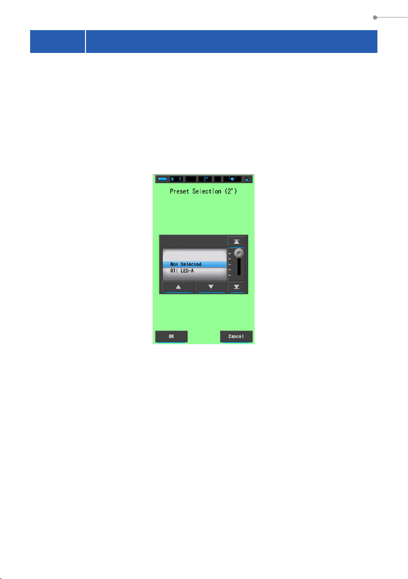
6. Measurement Tool [Tool Box] Screen
6-1
You can select a previously created Preset value from Preset Selection in the Tool
Box.
Select a preset item of Preset Selection (2°) or Preset Selection (10°).
If the "Preset Selection List" is set to be displayed in the "Preset Editing" function of
"Setting", only these preset items are displayed on the drum.
Setting Preset Contents [Preset Selection] Screen
Preset Selection (2°) Screen
80
Page 94

6. Measurement Tool [Tool Box] Screen
Operation
Touch the [Preset Selection (2°) (Preset Selection (10°))] button in
1.
the Tool Box.
The Preset Selection screen will be displayed.
Tool Box Screen Preset Selection (2°) Screen
NOTICE
A Preset value must be created and saved in the Preset Editing function
under the "Setting Mode" icon before it can be used.
Preset Selection buttons will be grayed out until settings are created.
Select desired preset no. (1 ~ 5).
2.
Match the blue background with the desired shutter speed.
Preset Selection Screen
Blue bar indicates the item selected.
[OK] Button
[Cancel] Button
81
Page 95

6. Measurement Tool [Tool Box] Screen
NOTICE
Be sure to set Preset Selection to "Not Selected" when no correction is
desired.
Touch the [OK] button.
3.
Conrm and return to the Measurement screen.
To return to the Measurement screen without conrming, touch the [Cancel] button.
Tool Box Screen
The set content is
displayed.
[Close] Button
Touch the [Close] button.
4.
Returns to the Measurement screen.
The selected status will be displayed on the status bar.
The preset is set.
The selected preset no. is displayed
82
.
Page 96

6. Measurement Tool [Tool Box] Screen
6-2 Using the Memory Function
The memory function enables storing light source data for single sources and
groups of sources for recall at any time. Up to 999 measurements can be stored.
Memory function also enables naming or renaming the title of memory and clearing
the stored value.
Tool Box
Screen
Memory Title
ScreenMemory Management Screen
Memory Recall Screen
Memory Edit Screen
Renaming Memory Title Clearing Memorized Value
83
Page 97

6. Measurement Tool [Tool Box] Screen
6-2-1 Naming Measurement Values Being Memorized
[Memory Title] Screen
You can create special titles for memorized values to make them easier to select, view
and use data later.
To use this function the order of operation:
* Create memory title
* Measure light source
* Press Memory button 7 to memorize
Memory Title Screen
The factory default
name is displayed.
NOTE
●
A title can be a maximum of 16 alphanumeric characters.
●
More than one measurement can be stored under one title.
●
Up to 999 titles can be created.
84
Page 98

6. Measurement Tool [Tool Box] Screen
Operation
Touch and select the [Memory Title] button in the Tool Box.
1.
The Memory Title screen will be displayed.
Tool Box Screen Memory Title Screen
Input
Section
Enter the memory title. (
2.
Use the keyboard to create a name for the measured light.
Memory Title Screen
Touch the [OK] button.
3.
Conrms and returns to the Tool Box screen.
To return to the Tool Box screen without conrming, touch the [Cancel] button.
P19)
[OK] Button
[Cancel] Button
85
Page 99

6. Measurement Tool [Tool Box] Screen
Touch the [Close] button.
4.
Returns to the Measurement screen.
Tool Box Screen
[Close] Button
The memory title is entered.
NOTICE
The memory title needs to be entered before memorizing.
The memory title can be edited and renamed at any time afterward using the
Memory Management function. (P93)
Measure light.
5.
Press Measuring Button 5 to take a measurement.
The Light Selection Ring 2 should be set to L ( )
when taking ambient light measurements.
When measuring ash units, select Range L ( )
or Range H ( ) depending on the brightness of
the ash. (P77, P78)
Measurement Screen
Measurement
86
Light Selection Ring
Measuring Button
2
5
Page 100

Press Memory Button 7 to memorize
6.
light source values and link the reading
to the created title name.
The Memory reected on the status bar.
6. Measurement Tool [Tool Box] Screen
Memory Button
7
87
 Loading...