

Transmitter
RT-20PW
RT-3PW
Operating Manual
This manual is specic for PocketWizard® operation.
Please read this operating manual so that you will fully understand the features and operation of this
product.
Keep the operating manual in a safe place for future use.
■
Safety Precautions
Before using this product, please read this "Safety Precautions" for proper operation.
WARNING
CAUTION
NOTICE
NOTE
The WARNING symbol indicates the possibility of death or serious
injury if the product is not used properly.
The CAUTION symbol indicates the possibility of minor to
moderate personal injury or product damage if the product is not
used properly.
The NOTICE symbol indicates cautions or restrictions when using
the product. Please read all notes to avoid errors in operation.
The reference symbol indicates additional information about the
controls or related functions.
Reading these is recommended.
The arrow indicates reference pages.
WARNING
Keep the materials used in this product out of the reach of children to
prevent accidental ingestion and misuse.
CAUTION
To avoid damage from static electricity, remove the static electricity from
your body by touching metals located nearby (e.g. door knob, aluminum
sash) before touching the radio transmitting module.
■
Terms and trademarks
PocketWizard® is the registered trademark of LPA Design.
NOTICE
● Reproduction of all or any part of this document without permission is strictly forbidden.
● The product concerned and/or this manual may be subject to changes without prior
notication.
● The screens in this manual may differ from the actual displays of the meter you are
using. (Colors, letters, etc.)
©2017 All Rights Reserved.

■
List of applicable model
This transmitter is an accessory dedicated to the following model (light meter).
Model
Transmitter Model Manufacturer/Frequency L-858D Series Serial No.
PocketWizard
RT-20PW
RT-3PW
■
Intended use
This product can be used in the following situations.
●
Radio wave-based ash light triggering or output power control.
●
Radio wave-based modeling lamp ON/OFF or output power control.
■
Intended users
The intended users of this product are as follows:
Those working in the areas of photography, lming, etc. such as photographers, who use
the ash units.
(FCC & Canada IC):
344.0 to 354.00 MHz
PocketWizard (CE & NCC):
433.42 to 434.42 MHz
JY11-XXXXXX(Canada IC)
JY1L- XXXXXX(FCC)
JY11-XXXXXX(CE)
JY1G- XXXXXX(NCC)
ii
■
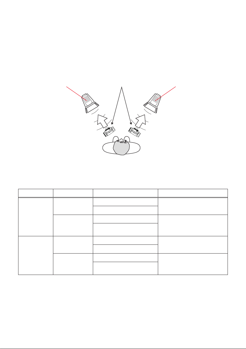
Features of the RT-20PW and RT-3PW
To use the Radio Triggering Mode of the L-858D after the transmitter is installed, the ash
unit must be equipped with a radio function supported by a specied manufacturer, or a
receiver supporting the radio function must be connected to the ash unit.
Using the Radio Triggering Mode, ring a ash or adjusting the output power by yourself
can be easily accomplished.
Light source
(with a receiver built-in/
installed)
Note that a transmitter of RT-20PW or RT-3PW can support two types of radio system.
The user can select which radio system to use in the custom setting of the L-858D light
meter.
For details on each radio system, refer to the descriptions in the relevant pages.
Regulation Radio System Radio CH/Zone Function
RT-20PW
FCC &
Canada IC
RT-3PW
CE & NCC
Standard
ControlTL
Standard
ControlTL
(with the transmitter installed)
Light meter
CH1 to 32 Flash light triggering
Zone: A to D
CH1 ~ 20 Flash light output power
Zone: A to C
CH1 to 32 Flash light triggering
Zone: A to D
CH1 to 3 Flash light output power
Zone: A to C
control and modeling lamp
ON/OFF
control and modeling lamp
ON/OFF
Light source
(with a receiver built-in/
installed)
iii

■
Restrictions
There are some cautions and restrictions regarding the use of this product.
Please read and understand the following before using the meter.
NOTE
● The contents of this manual may be subject to change for the product's specication
modications and other reasons without prior notice.
We recommend that you download the latest operating manual from our website and use
this product.
URL: www.sekonic.com/support/instructionmanualuserguidedownload.aspx
● The safety-related precautions such as "Safety Guide and Maintenance" and "Safety
Precautions" conform to the legal and industry standards that were applicable at the time
this operating manual was created. Therefore, this manual may not contain the latest
information. If you are using the previous operating manual, please download and refer to
the latest operating manual.
● The product may contain printing materials such as safety-related precautions and/or
errata to supplement the operating manual.
● The contents of this operating manual can only be reproduced for non-commercial
purposes and for personal use only. However, the reproduced material must contain the
copyright notice of our company.
However, such copies must have our copyright notice as a condition.
● The screens in this operating manual may differ from the actual displays of the meter you
are using. (Colors, text, etc.)
■
Accompanying Accessories
The following items are included with the transmitter. After opening the package. Please
be sure to check that all noted items are included.
If any items are missing, please contact the distributor or the reseller you purchased the
transmitter from.
Transmitter Startup Guide
iv

Table of Contents
■Safety Precautions
■Terms and trademarks
■List of applicable model
■Intended use
■Intended users
■Features of the RT-20PW and RT-3PW
■Restrictions
■Accompanying Accessories
1. Before Use
1-1
Installing the Transmitter
..............................................................................................................................................................
......................................................................................................................................................
..................................................................................................................................................
............................................................................................................................................................................
.......................................................................................................................................................................
............................................................................................................
..............................................................................................................................................................................
........................................................................................................................................
........................................................................................................................................................................
..........................................................................................................................
2. About PocketWizard Wireless Technology
2-1
How to use L-858D with PocketWizard Wireless Technology
2-2
Setting the Radio System
2-3
Setting the Radio CH/Zone
2-4
Radio Triggering Mode
2-4-1
Radio Triggering Flash Mode
2-4-2
Radio Triggering Multi (Cumulative) Flash Mode
2-4-3
Flash Duration Analysis Radio Triggering Mode
3. Product Information
.............................................................................................................................................
........................................................................................................................
.....................................................................................................................
..............................................................................................................................
.................................................................................................................
.................................................................................
...............................................
.......................................................................
.........................................................................
i
i
ii
ii
ii
iii
iv
iv
1
1
2
2
4
6
9
9
14
17
26
4. Regulation
.......................................................................................................................................................................
5. Radio Channel Frequencies
6. Legal Requirements
7. Troubleshooting
.............................................................................................................................................
.......................................................................................................................................................
.......................................................................................................................
v
28
29
30
31
1. Before Use ●
1.
Before Use
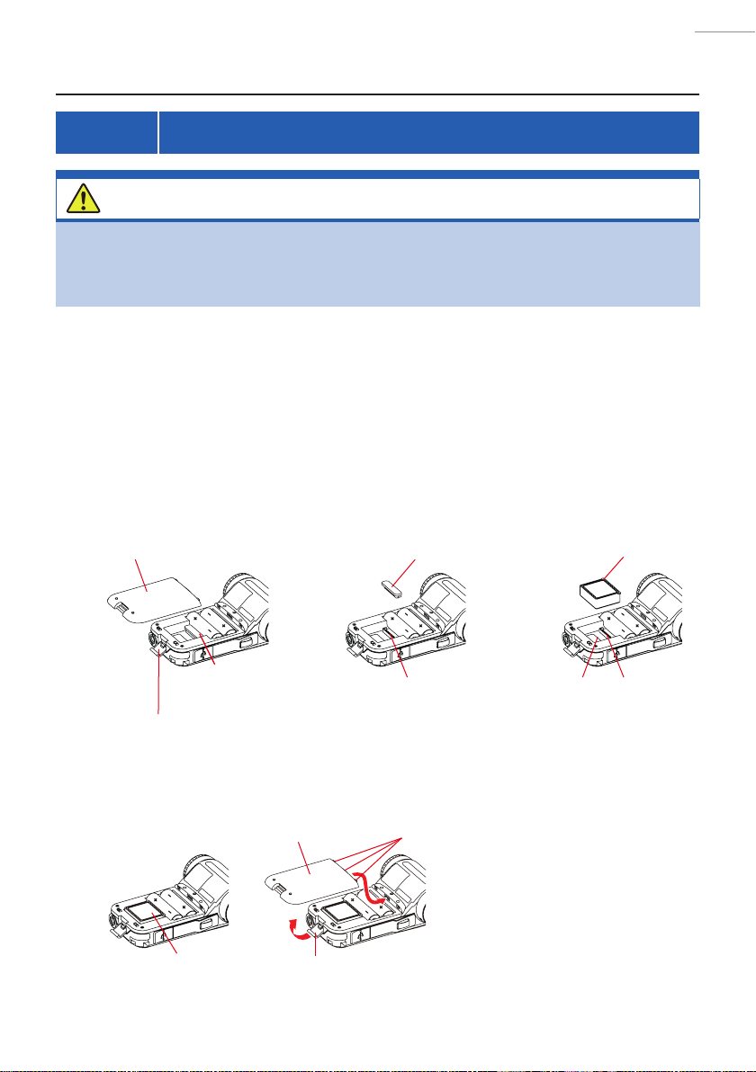
1-1 Installing the Transmitter
CAUTION
To avoid damage from static electricity, remove the static electricity from
your body by touching metal objects located nearby (e.g. door knob,
aluminum sash) before touching the radio transmitting module.
The numbering below refers to the L-858D Operating Manual.
Turn OFF the meter.
1.
Unlatch e and remove the Battery cover d.
2.
Remove the Transmitter connector cover i.
3.
Align the connector pins with those of the transmitter module
4.
compartment h and insert the Transmitter.
Battery cover
d
Transmitter connector cover
i
Transmitter
Transmitter connector
cover
i
Battery cover latch
Insert the Battery cover d tabs (three) into the receiving holes in
5.
the meter body, press the cover d down and latch e it closed.
Transmitter
e
Battery cover
Battery cover latch
Connector pins Connector
Tabs (three)
d
e
Transmitter module
compartment
h
1
pins

2. About PocketWizard Wireless Technology ●
2.
Plug-in external or built-in PocketWizard receivers are required to work with the
PocketWizard wireless technology.
Once the transmitter module is installed in your L-858D, you will be able to adjust the
power level and trigger ashes to get the look you desire. For more information about the
meter, refer to the L-858D Operating Manual.
For more information about PocketWizard, go to www.pocketwizard.com.
About PocketWizard Wireless Technology
2-1
<Standard System>
PocketWizard Standard system provides simple triggering and do not allow power
control. The Standard system features 32 channels: Channels 1-16 re single trigger
signals; Channels 17-32 have four zones (A, B, C, D) which enable triggering four
separate ashes on each channel.
<ControlTL System>
When used with ControlTL receivers, the L-858D is capable of controlling the power
level of the compatible ashes connected.
The ControlTL system features 20 channels for FCC&IC version or 3 channels for
CE version, and three zones (A, B, C) allowing control of three separate ashes on
each channel.
<Radio Frequency>
To comply with local broadcast regulations, Sekonic wireless systems sold in the
various markets around the world are designed to operate at different frequencies.
Sekonic meters have built-in transmitting antennas that are specically tuned for
their market area. When purchasing and/or installing a transmitter module or using
the meter with a receiver, be sure that the meter and receiver are designed to be
used in your location and use the same frequency.
How to use L-858D with PocketWizard
Wireless Technology
●
USA/North American market frequencies (FCC & Canada IC): 344.0 to 354.0MHz
●
European and other market frequencies (CE, NCC or OFCA): 433.42 to
434.42MHz
2

2. About PocketWizard Wireless Technology ●
NOTICE
Successful radio triggering depends on several factors. Please read these setup steps
before using the L-858D to radio trigger ash units.
1. It is the best to position the meter in sight of the radio receiver (or ash head).
2. Position the radio receiver so that it is away from large metallic objects, concrete, or
containers of water (like people).
3. Secure the radio receiver to the ash using hook-and-loop-type attachment tape or
the threaded socket on the radio. Make sure the radio’s antenna is above the ash
body or generator pack. Do not allow the receiver antenna to contact metal objects.
4. Sometimes, conditions do not allow radio reception. These could include strong
local radio interference or being near objects that block or absorb the signal.
Repositioning the radio, even slightly, can reestablish contact. Alternatively, check to
see if the radio receiver is behind objects that absorb or block radio waves, such as
concrete, metal or low hill.
5. Operation is the best when the meter to receiver distance is within 30 meters.
3
2. About PocketWizard Wireless Technology ●
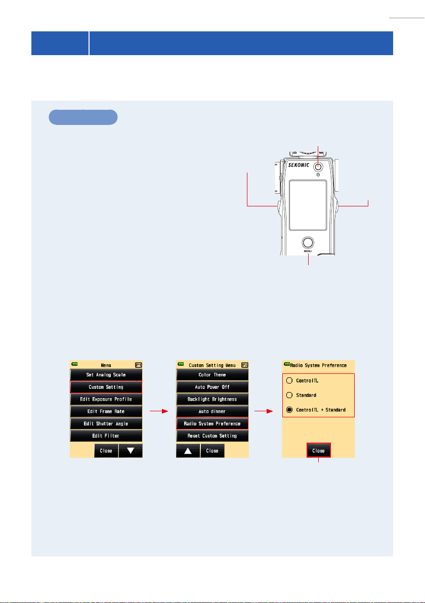
2-2 Setting the Radio System
In the Radio System Preference Screen, select Standard or ControlTL according to the
setting on the PocketWizard receiver.
Operation
Press the Menu Button on the meter.
1.
The Menu Screen is displayed.
Touch [Custom Setting] Button.
2.
The Custom Setting Menu Screen is
displayed.
Touch [Radio System Preference]
3.
Memory Button
7
Power Button
on page 3 of the Custom Setting
Menu Screen.
The Radio System Preference Screen is
displayed.
Touch the system to use.
4.
Touch the desired radio button or an area around the item name to select the
[ControlTL], [Standard] or both.
Menu Screen Custom Setting Screen
Radio System Preference
Menu Button
Screen
5
Measuring
Button
6
9
Touch the [Close] Button.
5.
The display returns to the Custom Setting Menu Screen.
Touch the [Close] on the Custom Setting Menu Screen.
6.
The display returns to the Menu Screen.
4
[Close] Button
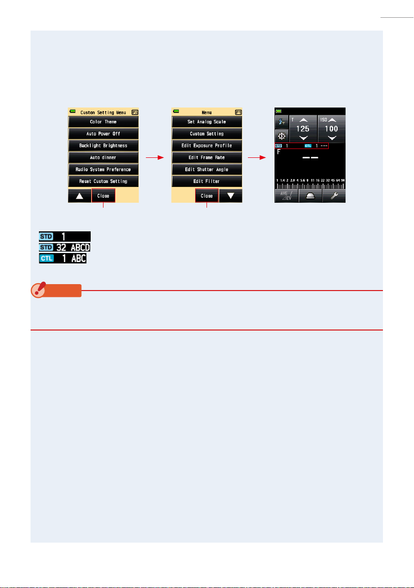
2. About PocketWizard Wireless Technology ●
Touch the [Close] Button on the Menu Screen.
7.
The display returns to the Measuring Screen.
The selected radio system indication along with channel number and zones are
displayed on the Measuring Screen.
Cutom Setting Screen Menu Screen Measuring Screen
[Close] Button [Close] Button
Standard System, Channel (1 to 16)
Standard System, Channel (17 to 32) and Zones (A to D)
ControlTL System, Channel and Zones (A to C)
NOTICE
Set both the meter and plug-in external or built-in PocketWizard receivers to the same
system (Standard and/or ControlTL).
5
2. About PocketWizard Wireless Technology ●
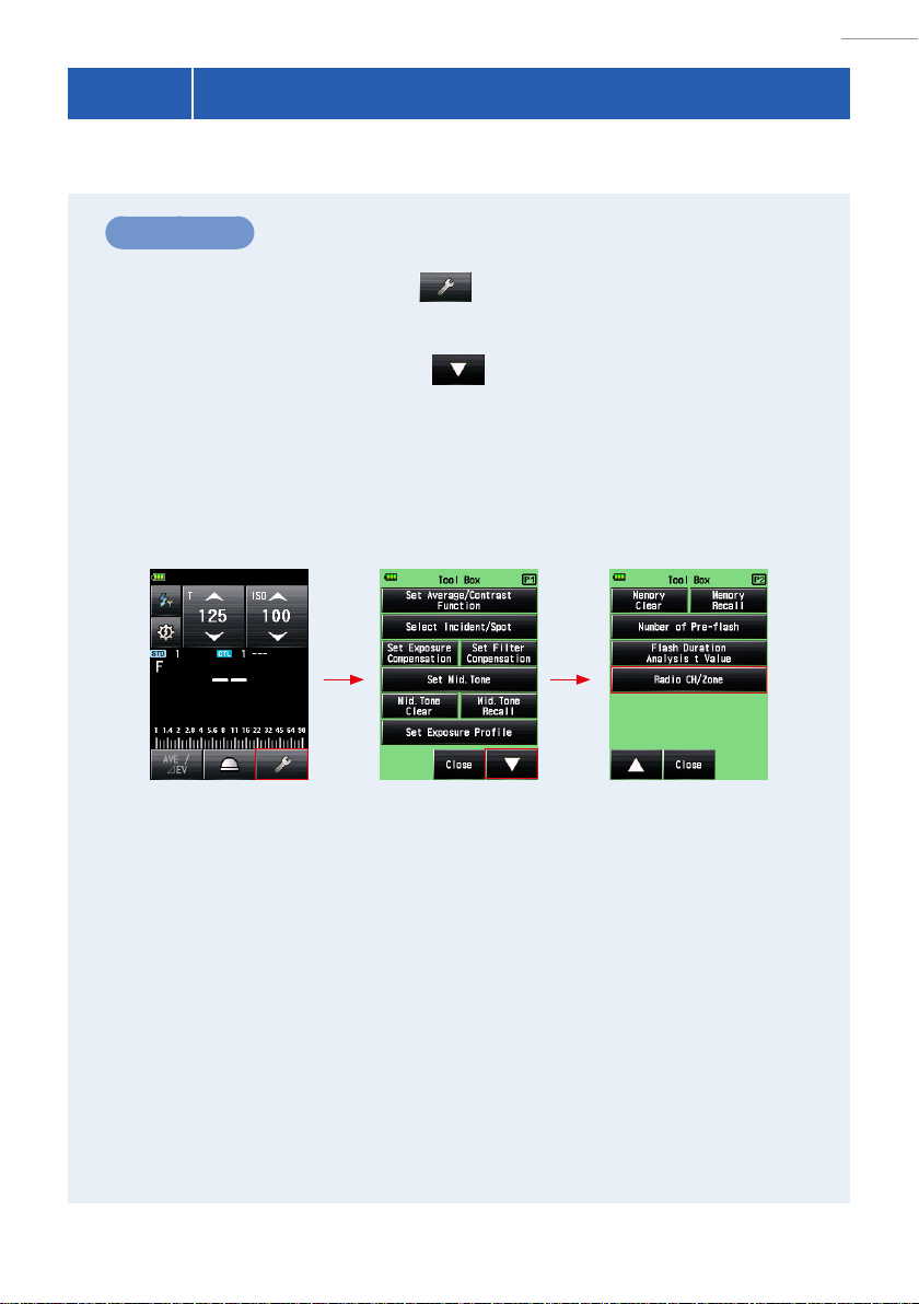
2-3 Setting the Radio CH/Zone
Set the radio channel and zones used on Standard System.
Operation
Touch the [Tool Box] Icon ( ) on the Measuring Screen.
1.
The Tool Box Screen is displayed.
Touch the [Next Page] Icon ( ) of the Tool Box to display the
2.
Tool Box showing “Radio CH/Zone”.
Touch [Radio CH/Zone] Button.
3.
The Radio CH/Zone Screen is displayed.
Measuring Screen
Tool Box Screen
Page 1
* When the Multiple (Cumu.) Flash Mode is
selected, the displayed information are different
from those shown above.
Tool Box Screen
Page 2
6

2. About PocketWizard Wireless Technology ●
Touch the [STD] or [CTL] tab to select the radio system.
4.
STD stands for Standard, and CTL stands for ControlTL.
STD tab CTL tab
Zones Zones
Channel numbers Channel numbers
Select the channel to use.
5.
Touch the arrows / or slide your nger over the screen to select
Channel.
Standard: from 1 to 32.
ControlTL: from 1 to 20 (for FCC and Canada IC), from 1 to 3 (for CE and NCC)
Touch one or more Zones to select the ash units you want to
6.
use.
Stanard: from A to D (When the channel number from 17 to 32 is selected, Zones
appear.)
ControlTL: From A to C
* Zones to use can be selected from Power Control Screen as well.
7

2. About PocketWizard Wireless Technology ●
Touch [OK] to conrm settings and return to the Measuring
7.
Screen.
(Touch [Cancel] to go back to the Measuring Screen without change.)
Radio CH/Zone Setting Screen
(When Standard Channel is selected) Measuring Screen
[STD] tab
Zones
[OK] Button [Cancel] Button
NOTICE
Set both the meter and plug-in external or built-in PocketWizard receivers to the same radio
system (Standard or ControlTL).
NOTE
● The last selected Zones in either Power Control Screen or Radio CH/Zone Setting
Screen in Tool Box are activated in Measuring Screen.
● For touch/slide operations, refer to the Operating Manual of the light meter.
● For radio CH frequencies, refer to “5. Radio Channel Frequencies”. ( P29)
8

2. About PocketWizard Wireless Technology ●
2-4 Radio Triggering Mode
Radio triggering measurement is available in the following modes:
●
Radio Triggering Flash Mode
●
Radio Triggering Multi (Cumulative) Flash Mode
●
Flash Duration Analysis Radio Triggering Mode
2-4-1 Radio Triggering Flash Mode
The meter detects ash brightness after Measuring Button is pressed to send radio
transmitted signal to radio receiver connected to ash. F-stop value is displayed for input
ISO sensitivity and shutter speed. Depending on the radio system in use, the meter
controls the output power of ash units and turn ON/OFF the modeling lamps.
Operation
How to Use Flash Triggering
1)
Touch the [Measuring Mode] Icon on the Measuring Screen.
1.
The Measuring Mode Screen is displayed.
Touch the [Measuring Mode] Icon ( ) in Measuring Screen.
2.
When it is selected, the display changes to the Measuring Screen.
Measuring Screen Measuring Mode Screen Measuring Screen
[Measuring Mode] Icon
Set the light receiving method.
3.
Switch to the Incident light, extended lumisphere ( )/retracted lumisphere
( ), or reected light.
9

2. About PocketWizard Wireless Technology ●
Set the ISO sensitivity value on the [ISO]
4.
Measuring Screen
Icon.
Set the shutter speed on the [T] Icon.
5.
Setting Value
NOTICE
Make sure that the settings are within the specications of the camera and ash system.
Make sure that the channel and Zones are
6.
Measuring Screen
the same for the meter and receivers in use.
(P4, P6)
10
Radio CH and Zones

2. About PocketWizard Wireless Technology ●
Press the Measuring Button 6.
7.
The ash will re and the measured value (F-stop) will
be displayed.
Measuring Screen
Measured value
(F-stop)
NOTICE
● In case of the followings, please follow “Cord Flash Mode”.
• When ring the ash, if the ash brightness is lower than the ambient light, the meter
may fail to detect the ash light.
• Rapid start uorescent lamps and special lighting are sometimes mistaken for ash,
and accidentally measured.
• Even if the ash is not red, when a sudden light change occurs in the light receptor,
measurement may be made.
• The waveform of a ash bulb has a slight slope and there is a possibility that the light
meter cannot recognize the ashbulb in Cordless Flash Mode.
NOTE
● For radio CH frequencies, refer to “5. Radio Channel Frequencies”. ( P29)
11

2. About PocketWizard Wireless Technology ●
How to Use Flash Power Control
2)
Power Control Function is available with ControlTL system only. Make sure that plugin external or built-in PocketWizard receivers and ash unites are compatible with the
function of ash power control.
Touch the [Power Control] Icon ( ) on the Measuring Screen.
1.
The Power Control Screen is displayed.
Select one or more Zones (A to C) 4 and the Power Bar 2 will be
2.
activated.
Only ash unit with the receiver set to the selected Group is red.
Measuring Screen Power Control Screen
1
5
2
3
4
[Power Control] Icon
Press the Measuring Button 6.
3.
The ash units of the selected Zones are red, and the
measured value (F-stop) is displayed at the top of the bar 1
and the “F Total” box at the bottom right of the screen 6.
Move the slider or touch the [+] or [ - ] Icons 2
4.
6
Power Control Screen
to change the power of ash.
The set power level is displayed in the area above the slider
.
1
NOTICE
Although up to +/- 3 step of value (f stop) can be set, the adjustment must be within the
upper and lower limit of the power level specication of the ash unit.
12

2. About PocketWizard Wireless Technology ●
Press the Measuring Button 6 again.
5.
Check that the output power of the ash is the desired
value.
Repeat Steps 2 to 5.
6.
Repeat the procedure for other Zones until each ash unit’s
brightness is set to proper value for the effect you want.
Select all Zone buttons you want to use, and
7.
Power Control Screen
(After Measurement)
press the Measuring Button 6.
Measured value of each Zone 3 will not change. The
F-number for the measured brightness of all lights will be
displayed in the “F Total” box 6.
NOTE
● To set ISO sensitivity and shutter speed, press the [Radio Triggering Flash Mode] Icon
( ) to return to the Measuring Screen.
● The last selected zones in either Power Control Screen or Radio CH/Zone Setting
Screen in Tool Box are activated in Measuring Screen.
● Standard system radios can be used along with ControlTL system radios to trigger nonpower control ashes at the same time. When a Standard channel number is set from 1
to 16, ( ) (classic channel) button appears 5. When a channel number from 17 to 32
is selected, the Zones (A to D) will appear at the right of the screen 7 . Touch ( ) or
Zones (A to D) to toggle them on or off.
Power Control Screen
(Standard CH1 to 16)
Power Control Screen
(Standard CH17 to 32)
● Press Modeling Lamp ON ( ) or OFF ( ) if necessary after selecting the desired
Zones.
13

2. About PocketWizard Wireless Technology ●
2-4-2 Radio Triggering Multi (Cumulative) Flash Mode
This Measuring Mode is used when the light generated by the ash at one time is
inadequate for the desired F-stop setting. Repeated ash pops can be accumulated
until the desired F-stop value is displayed. The measured value (F-stop) is displayed for
each trigger of the ash. The cumulative count is innite. Up to 99 times is displayed in
the Status/Title eld, however, the cumulative count returns to 0(zero) for more than 100
times (0=100, 1=101, 2=102, etc.).
Operation
How to Use Flash Triggering
1)
Touch the [Measuring Mode] Icon on the Measuring Screen.
1.
The Measuring Mode Screen is displayed.
Touch the desired Icon ( ) in Measuring Mode.
2.
When it is selected, the display changes to the Measuring Screen.
Measuring Screen
[Measuring Mode] Icon
Set the light receiving method.
3.
Switch to the Incident light, extended lumisphere ( )/
retracted lumisphere ( ), or reected light.
Set the ISO sensitivity value on the [ISO] Icon.
4.
Set the shutter speed on the [T] Icon.
5.
Measuring Mode
Selection Screen Measuring Screen
Measuring Screen
Setting Value
14

2. About PocketWizard Wireless Technology ●
NOTICE
Make sure that the settings are within the specications of the camera and ash system.
Make sure that the channel and Zones are
6.
Measuring Screen
the same for the meter and receivers in use.
(P4, P6)
Radio CH and Zones
Press the Measuring Button 6.
7.
The measured value (F-stop) is
displayed. Press the Measuring
Button again to re a ash and
measure until the desired F-stop is
displayed.
The accumulated measured value
(F-stop) and the cumulative count are
displayed.
Cumulative count
Measured value
(F-stop)
NOTICE
● In case of the followings, please follow “Cord Flash Mode”.
• When ring the ash, if the ash brightness is lower than the ambient light, the meter
may fail to detect the light.
• Rapid start uorescent lamps and special lighting are sometimes mistaken for ash
and accidentally measured.
• Even if the ash is not red, when a sudden light change occurs in the light receptor,
measurement may be made.
• The waveform of a ash bulb has a slight slope and there is a possibility that the light
meter cannot recognize the ash bulb in Cordless Flash Mode.
● The EV scale cannot be displayed in the Multiple (Cumu.) Flash Mode.
Measuring Screen
NOTE
For radio CH frequencies, refer to “5. Radio Channel Frequencies”. ( P29)
15

2. About PocketWizard Wireless Technology ●
Multi Clear
2)
Touch the [Tool Box] Icon ( ) on the Measuring Screen.
1.
The Tool Box Screen is displayed.
Touch the [Next Page] Icon ( ) of the Tool Box to display the
2.
Tool Box showing “Multi Clear”.
This button is only enabled during measurement.
If the button is grayed out, the cumulative measurement is not made and the count
cannot be cleared.
Touch the [Multi Clear] Button of the Tool Box.
3.
The cumulate value is cleared, and the display returns to the Measuring Screen.
If you do not clear the value, touch the [Close] Button.
The display returns to the Measuring Screen.
Measuring Screen
Measuring Screen Cumulative count
Cumulative count
Tool Box Screen
Page 1
To Next Page [Close] ButtonCumulative count
Tool Box Screen
Page 2
16

2. About PocketWizard Wireless Technology ●
2-4-3 Flash Duration Analysis Radio Triggering Mode
The meter detects ash brightness after Measuring Button is pressed to send radio
transmitted signal to radio receiver connected to ash. F-stop, ash duration time and
graph of ash waveform are displayed for input ISO sensitivity and shutter speed.
Depending on the receivers in use, the meter controls the output power of ash units
and modeling lamp with turning ON/OFF, however, ash duration time and graph of ash
waveform are not measure in Modeling Lamp Power Control Screen because it is ambient
light not ash light.
Flash Duration Analysis is performed with incident light Measuring Mode.
Operation
How to Use Radio Triggering
1)
Touch the [Measuring Mode] Icon on the Measuring Screen.
1.
The Measuring Mode Screen is displayed.
Touch the desired icon ( ) in Measuring Mode.
2.
When it is selected, the display changes to the Measuring Screen.
If the Reected Light Mode is set, the Flash Duration Analysis Mode cannot be selected.
Before switching to the Measuring Mode Selection Screen, set the light receiving
method to the incident light and select the Flash Duration Analysis Mode.
Measuring Screen Measuring Mode Screen Measuring Screen
[Measuring Mode] Icon
Set the light receiving method.
3.
Switch to the extended lumisphere ( ) or retracted lumisphere ( ).
17

2. About PocketWizard Wireless Technology ●
Set the ISO sensitivity value on the [ISO]
4.
Icon.
Set the shutter speed on the [T] Icon.
5.
NOTICE
● Make sure that the settings are within the specications of
the camera and ash system.
● If the measured ash duration time is longer than the input
shutter speed, an appropriate F-stop cannot be measured.
The yellow “Under” indication appears. In this case, slower
the shutter speed than the ash duration time and measure
again.
Set the Flash Duration Analysis t value. ( P17)
6.
Measuring Screen
Setting Value
Measuring Screen
Make sure that the channel and Zones are
7.
the same for the meter and receivers in use.
(P4, P6)
18
Measuring Screen
Radio CH and Zones

2. About PocketWizard Wireless Technology ●
Press the Measuring Button 6.
8.
The ash will re, and the ash duration time and the measured value (F-stop) for
input ISO sensitivity and shutter speed will be displayed.
Measuring Screen
Flash component
Flash duration time
Measured value (F-stop)
NOTICE
● The ash duration time and graph are displayed in the Flash Duration Analysis Mode,
however, they cannot be stored in the memory. They are cleared if the Measuring Mode
is changed or the POWER Button is turned OFF.
● The incident light measurement can only be used in Flash Duration Analysis Mode.
● In case of the followings, please follow “Flash Duration Analysis Cord Mode”.
• When ring the ash, if the ash brightness is lower than the ambient light, the meter
may fail to detect the light.
• Rapid start uorescent lamps and special lighting are sometimes mistaken for ash
and accidentally measured.
• Even if the ash is not red, when a sudden light change occurs in the light receptor,
measurement may be made.
• The waveform of a ash bulb has a slight slope and there is a possibility that the light
meter cannot recognize the ash bulb in Cordless Flash Mode.
19

2. About PocketWizard Wireless Technology ●
NOTE
● When the measured value display area is touched, both ash waveform graph and measured
value are displayed. When it is touched again, the display returns to the previous screen.
Measuring Screen
Flash Duration Analysis Cordless
Mode Flash Waveform Graph Screen
Touching the
Measured
value area
changes the
display.
* The graph screen cannot be used to make measurements.
● Measure the ash light characteristics in a darkroom without ambient light.
● For radio CH frequencies, refer to “5. Radio Channel Frequencies”. ( P29)
20

2. About PocketWizard Wireless Technology ●
How to use Flash Power Control
2)
Power Control Function is available with ControlTL system only. Make sure that plugin external or built-in PocketWizard receivers and ash units are compatible with the
function of ash power control.
Set the Flash Duration Analysis t value. ( P24)
1.
Make sure that the channel and Zones are the same for the meter
2.
and receivers in use. ( P4, P6)
Touch the [Power Control] Icon ( ) on the Measuring Screen.
3.
The Power Control Screen is displayed.
Select one or more Zones (A to C) 4 and the Power Bar 2 will be
4.
activated.
Only ash unit with the receiver set to the selected Group is red.
Measuring Screen
Power Control Screen
(ControlTL+Standard CH1 to 16)
1
5
2
[Power Control] Icon
21
3
4
6

2. About PocketWizard Wireless Technology ●
Press the Measuring Button 6.
5.
The ash units of the selected Zones are red, and
the measured value (F-stop) is displayed at the top
of the bar 1 and the “F Total” box at the bottom
right of the screen 6 .
Move the slider or touch the [+] or [-]
6.
Power Control Screen
(ControlTL+Standard CH1 to 16)
Icons 2 to change the power of ash.
The set power level is displayed in the area above
the slider 1 .
NOTICE
Although up to +/- 3 step of value (f stop) can be set, the adjustment must be within the
upper and lower limit of the power level specication of the ash unit.
Press the Measuring Button 6 again.
7.
Check that the output power of the ash is the desired value.
Press [Measuring Mode] Icon ( ).
8.
The display returns to the Measuring Screen, and the ash duration time and
the measured value (F-stop) for input ISO sensitivity and shutter speed will be
displayed.
Power Control Screen
(After Measurement) Measuring Screen
22

2. About PocketWizard Wireless Technology ●
NOTE
● When the measured value display area is touched, both ash waveform graph and measured
value are displayed. When it is touched again, the display returns to the previous screen.
Measuring Screen
Flash Duration Analysis Cordless
Mode Flash Waveform Graph Screen
Touching the
Measured
value area
changes the
display.
* The graph screen cannot be used to make measurements.
● Measure the ash light characteristics in a darkroom without ambient light.
● When using a ash with a pre-ash function, set the “Number of Pre-ash” in the Tool
Box to cancel out the pre-ashing. ( P24)
● To set ISO sensitivity and shutter speed, press the [Radio Triggering Flash Mode] Icon
(
) to return to the Measuring Screen.
● The last selected zones in either Power Control Screen or Radio CH/Zone Setting
Screen in Tool Box are activated in Measuring Screen.
● For radio CH frequencies, refer to “5. Radio Channel Frequencies”. ( P24)
23

2. About PocketWizard Wireless Technology ●
Flash Duration Analysis t Value
3)
The t value can be set in steps of 0.1 at a range of 0.1 to 0.9.
The ash duration time varies depending on the input t value.
Touch the [Tool Box] Icon ( ) on the Measuring Screen.
1.
The Tool Box Screen is displayed.
Touch the [Next Page] Icon ( ) of the Tool Box to display the
2.
Tool Box showing “Number of Pre-ash”.
This button is enabled if Flash Duration Analysis Mode is selected. If it is not
grayed out, check the Measuring Mode.
Touch the [Flash Duration Analysis t Value] Button of the Tool
3.
Box.
The Flash Duration Analysis t Value Screen is displayed.
If you do not change this number, touch the [Close] Button.
Measuring Screen
Tool Box Screen
Page 1
To Next Page [Close] Button
Tool Box Screen
Page 2
24

2. About PocketWizard Wireless Technology ●
Enter the “Reference” of 0.1 to 0.9 by touching the numeric value.
4.
The t value can be set in steps of 0.1 at a range of 0.1 to 0.9.
The rst “0.” is xed. Enter the rst digit decimal only. (To set “0.1”, enter “1”.)
Flash Duration Analysis t Value Screen
The input numeric
value is displayed.
[OK] Button [Cancel] Button
Touch [OK].
5.
The setting is entered, and the display returns to the Measuring Screen.
Touch the [Cancel] Button to return to the Measuring Screen without making the
modication.
Measuring Screen
NOTE
Two rules apply to the reference ash duration
time.
t0.5 = Effective ash duration time
t0.1 = Total ash duration time
After ash ring, the time at which the
maximum intensity drops by half is called “t0.5”.
The time at which the maximum intensity drops
to 1/10 is called “t0.1”.
Generally, “t0.5” is called the ash duration
time.
25
t
0.9
t
0.8
t
0.7
t
0.6
t
0.5
t
0.4
t
0.3
t
0.2
t
0.1

3. Product Information ●
3.
This screen displays the detailed information not displayed in the Measuring Screen.
Product Information
Product Information Screen
No. Item Description
1
Model
1
2
3
4
5
* The screen contents
above differ depending
on models.
Serial
2
Version
3
User
4
Information
Radio module
5
Displays the model number of
the meter.
Displays the serial number of
the meter.
Displays the rmware version.
Displays user-input information
such as ownership or meter
function, etc which is set in the
Hardware Setting.
Displays the type of radio
system.
Operation
Touch the Menu Button 9 on the meter.
1.
The Menu Screen is displayed.
Touch the [Next Page] Icon ( ) to display page 2 of the Menu
2.
Screen, and touch the [Product Information] Icon.
The Product Information Screen is displayed.
Menu Screen
Page 2
Product Information
Screen
[Close] Button [Close] Button
Menu Screen
Page 2
26

Touch the [Close] Icon.
3.
The display return to the Menu Screen.
Touch the [Close] Icon.
4.
The display returns to the Measuring Screen.
3. Product Information ●
27

4. Regulation ●
4.
The Regulation Screen displays the symbols, approved number, regulation names, etc.
which the meter is compliance with.
* The contents on the Regulation Screen vary depending on the destination or whether a
Regulation
transmitter (sold separately) is installed.
Operation
Touch the Menu Button 9 on the meter.
1.
The Menu Screen is displayed.
Touch the [Next Page] Icon ( ) to display page 2 of the Menu
2.
Screen, and touch the [Regulation] Icon.
The Regulation Screen is displayed.
Menu Screen
Page 2
Regulation Screen
Menu Screen
Page 2
[Close] Button [Close] Button
Touch the [Close] Icon.
3.
The display return to the Menu Screen.
Touch the [Close] Icon.
4.
The display returns to the Measuring Screen.
28

5. Radio Channel Frequencies ●
5.
Radio wave frequency:
Zone: Standard System: A to D (from CH 17 to CH 32)
ControlTL System: A to C (all channel)
Radio triggering range: 30 meter (100 feet)
Radio Channel Frequencies
Regulation Radio System Channel Number Frequency
RT-20PW
FCC & Canada IC
RT-3PW
CE & NCC
NOTE
The working distance of the radio triggering system can vary with the orientation and
location of the meter and receivers.
Standard CH1 ~ 16 344.04MHz
CH17 ~ 32 346.5 ~ 354.0MHz
ControlTL CH1 ~ 4 340.0 ~ 346.0MHz
CH5 ~ 20 341.5 ~ 351.0MHz
Standard CH1 ~ 16 433.62MHz
CH17 ~ 32 434.22MHz
ControlTL CH1 ~ 3 433.42 ~ 434.42MHz
29

6. Legal Requirements
●
6.
This product complies with the following legal requirements.
FCC & IC compliance information:
Compliance statement to FCC and Industry Canada
This device complies with Part 15 of the FCC Rules.
Operation is subject to the following two conditions:
(1) this device may not cause harmful interference, and
(2) this device must accept any interference received, including interference that may cause
The user is cautioned that unauthorized changes or modications not approved could void the
user’s authority to operate the equipment.
Legal Requirements
Destination Standard Details
Europe CE
North America FCC
(US)
IC (Canada) Wireless
FCC ID: PFK-RT20-01
undesired operation.
Wireless EN300 220-2 V2.4.1
EN301 489-1 V1.9.2
EN301 489-3 V1.6.1
EN62479:2010
Wireless FCC Part15 SubpartC
RSS-210 Issue9
IC: 3916A-RT20001
Operation is subject to the following two conditions:
(1) this device may not cause interference, and
(2) this device must accept any interference, including interference that may cause undesired
operation of the device.
Le present appareil est conforme aux CNR d’Industrie Canada applicables aux appareils radio
exempts de licence. L’exploitation est autorisee aux deux conditions suivantes :
(1) l’appareil ne doit pas produire de brouillage, et
(2) l’utilisateur de l’appareil doit accepter tout brouillage radioelectrique subi, meme si le
brouillage est susceptible d’en compromettre le fonctionnement.
30

7. Troubleshooting ●
7.
Troubleshooting
If your meter is not operating properly, as you expect, please consult the following
conditions and attempt the suggested solutions before contacting Sekonic. Nonoperation can be due to incorrect, mis-setting of the meter or battery condition.
Should your meter be malfunctioning, please contact place where meter was
purchased or Sekonic for service and repair.
Condition Possible reasons What to do
Flash cannot be
triggered in Radio
Triggering Flash
Mode.
Is the radio receiver in the
ash compatible with the
meter’s transmitter? Isn’t any
other non-compatible brand or
manufacturer used?
Are the meter transmitter and
receivers set for the same
channel number?
Are the meter and receiver set
for the same ControlTL and/or
Standard channel and zones?
Are the meter transmitter
and receiver set for the same
frequency?
Make sure that both the meter
and plug-in external or built-in
PocketWizard receivers to the same
system (Standard and/or ControlTL).
http://www.pocketwizard.com/
Set the same channel number and
zones on the transmitter and the
receivers.
Check that the transmitter and
receiver are both set to the same
system (either the standard system
or ControlTL system).
As there are two types of frequency
(344 MHz band and 433 MHz
band), ensure that the transmitter
and frequency have the same
specications.
31

7-24-14, Oizumi-Gakuen-cho, Nerima-ku Tokyo
178-8686 JAPAN
Tel +81-3-3978-2335 Fax +81-3-3978-5229
http://www.sekonic.com
February 2017
JX5197630
 Loading...