

Sega The House Of The Dead 4 29""STD, The House Of The Dead 4 62""DX, The House Of The Dead 4 52""DX Owner's Manual

BEFORE USING THE PRODUCT,
To maintain safety:
To ensure the safe operation of this product, be sure to read the following before usage.
The following instructions are intended for the users, operators and the personnel in charge of the
operation of the product. After carefully reading and sufficiently understanding the warning
displays and cautions, handle the product appropriately. Be sure to keep this manual close to the
product or in a convenient place for future reference.
Herein, explanations which require special attention are enclosed with dual lines. Depending on
the potentially hazardous degrees, the terms of DANGER, WARNING, CAUTION, etc. are used.
Be sure to understand the contents of the displays before reading the text.
BE SURE TO READ THE FOLLOWING:
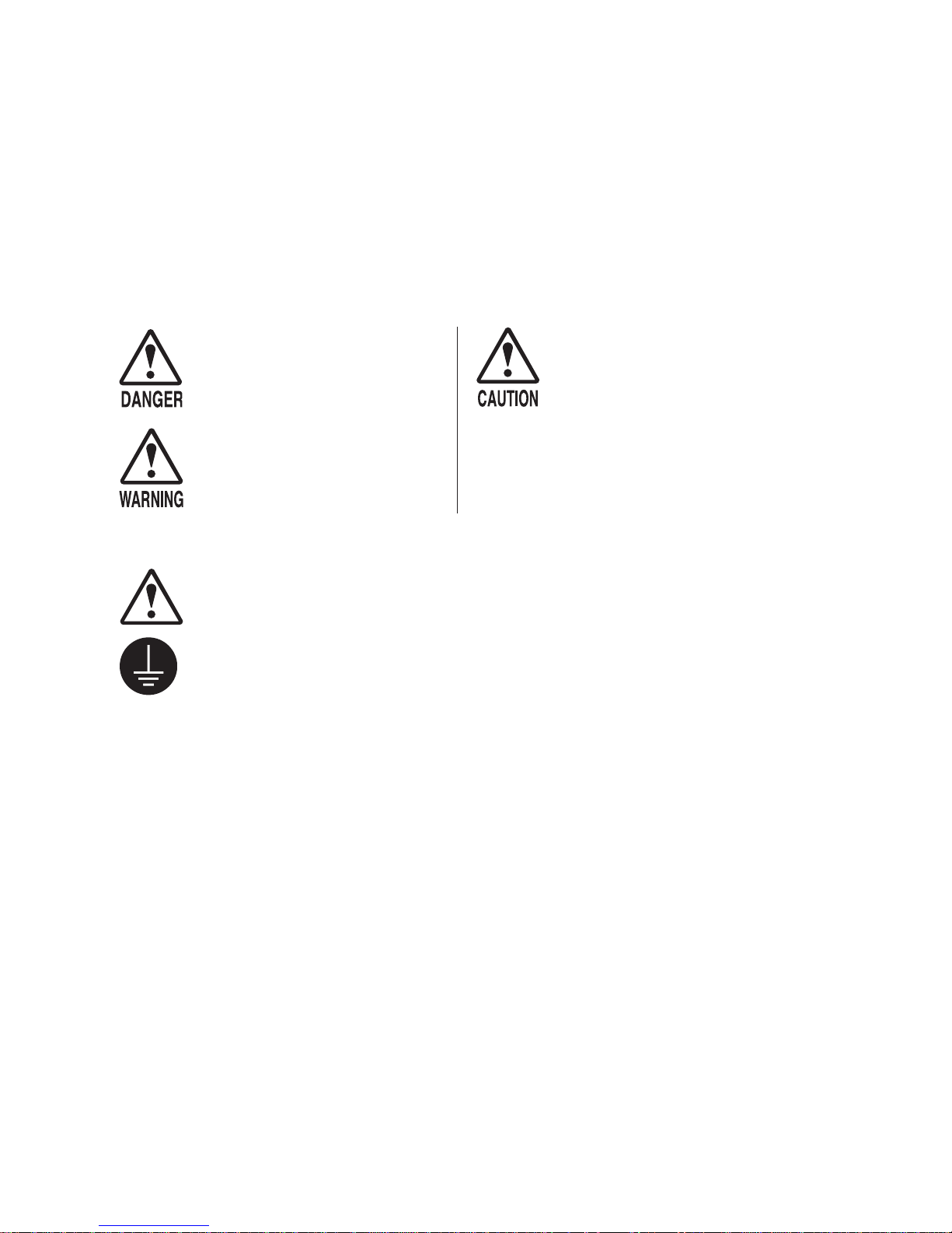
Indicates that mishandling the
product by disregarding this
pictograph will cause severe
injury or death.
Indicates that mishandling the
product by disregarding this
warning will cause a potentially
hazardous situation which can
result in death or serious injury.
For the safe usage of the product, the following pictographs are used:
Indicates "HANDLE WITH CARE." In order to protect the human body and
equipment, this display is attached to places where the Owner's Manual, Serviceman
Manual and/or Service Manual should be referred to.
Indicates a "Protective Earth Terminal." Before operating the equipment, be sure to
connect it to the Ground.
(The step may be omitted for products in which a power cord with earth is used.)
❍ Perform work in accordance with the instructions herein stated.
Instructions for work are explained by paying attention to the aspect of accident prevention.
Failing to perform work as per the instructions can cause accidents. In the case where only
those who have technical expertise should perform the work to avoid hazardous situation, the
instructions herein state that the site maintenance personnel should perform such work.
❍ Be sure to turn off the power before working on the machine.
To prevent an electric shock, be sure to turn off the power before carrying out any work that
requires direct contact with the interior of the product. If the work is to be performed in the
power-on status, the Instruction Manual herein always states to that effect.
❍ Be sure to ground the Earth Terminal.
(This is not required in the case where a power cord with earth is used.)
This product is equipped with the Earth Terminal. When installing the product, connect the
Earth Terminal to the "accurately grounded indoor earth terminal" by using an earth wire.
Unless the product is grounded appropriately, the user can be subject to an electric shock.
After performing repair, etc. for the control equipment, ensure that the Earth Wire is firmly
connected to the control equipment.
❍ Ensure that the Power Supply used is equipped with an Earth Leakage Breaker.
This product does not incorporate the Earth Leakage Breaker. Using a power supply which is
not equipped with the Earth Leakage Breaker can cause a fire when earth leakage occurs.
❍ Be sure to use fuses which meet the specified rating.
(Only for the machines which use fuses.)
Using fuses exceeding the specified rating can cause a fire and an electric shock.
Indicates that mishandling the
product by disregarding this
caution will cause a slight
hazardous situation which can
result in personal injury and/or
material damage.

TABLE OF CONTENTS
BEFORE USING THE PRODUCT, BE SURE TO READ THE FOLLOWING:
TABLE OF CONTENTS
INTRODUCTION
1. HANDLING PRECAUTIONS............................................................. 1
2. PRECAUTIONS REGARDING INSTALLATION LOCATION............. 3
2-1 LIMITATIONS OF USAGE....................................................... 3
2-2 OPERATION AREA................................................................. 3
3. PRECAUTIONS REGARDING PRODUCT OPERATION.................. 4
3-1 BEFORE OPERATION............................................................ 4
3-2 DURING OPERATION
(PAYING ATTENTION TO CUSTOMERS).............................. 5
4. PART DESCRIPTIONS...................................................................... 6
5. ACCESSORIES................................................................................. 7
6. ASSEMBLY AND INSTALLATION...................................................... 7
7. PRECAUTIONS WHEN MOVING THE MACHINE............................ 17
8. GAME DESCRIPTION....................................................................... 18
9. EXPLANATION OF TEST AND DATA DISPLAY................................ 20
9-1 SWITCH UNIT AND COIN METER......................................... 21
9-2 SYSTEM TEST MODE............................................................ 21
9-3 GAME TEST MODE................................................................ 26
10. CONTROL UNIT (GUN)..................................................................... 33
11. DLP (Digital Light Processor) PROJECTOR...................................... 36
11-1 CLEANING THE SCREEN...................................................... 94
12. REPLACING THE FLUORESCENT LIGHTS AND LAMPS............... 36
12-1 BILLBOARD FLUORESCENT LIGHT (52”/62”DX)................. 37
12-2 HOLSTER FLUORESCENT LIGHT........................................ 37
13. PERIODIC INSPECTION.................................................................. 38
14. TROUBLESHOOTING....................................................................... 39
14-1 PROBLEMS NOT INVOLVING THE GAME BOARD.............. 39
14-2 ERROR CODES...................................................................... 43
14-3 REPLACING THE FUSE......................................................... 45
15. GAME BOARD................................................................................... 46
15-1 REMOVING THE GAME BOARD............................................ 46
15-2 COMPOSITION OF THE GAME BOARD................................ 47
16. DESIGN RELATED PARTS................................................................ 48
17. PARTS LIST........................................................................................ 50
18. WIRE COLOR CODE TABLE............................................................. 60
19. CABINET WIRING DIAGRAM
- i -
INTRODUCTION
This manual is intended to provide detailed descriptions together with all the necessary
information covering the general operation of electronic assemblies, electromechanicals, servicing control, spare parts, etc. for the product, "The House of the
Dead 4."
This manual is intended for the owners, personnel and managers in charge of operation
of the product.
Operate the product after carefully reading and sufficiently understanding the
instructions.
In the unlikely event that the product does not function correctly, DO NOT allow
anyone other than a technician to touch the internal system. Turn off the power to the
machine, making sure to unplug the electrical cord from the outlet, and contact the
office listed below or the point-of-purchase for this product.
Use of this product is unlikely to cause physical injuries or damage to property.
However, points that require special attention are indicated by thick underlining, the
word "IMPORTANT" and the symbol below.
Indicates important information that, if ignored, may result in the
mishandling of the product and cause faulty operation or damage to the
product.
SEGA AMUSEMENTS U.S.A., INC./ CUSTOMER SERVICE
800 Arthur Avenue. Elk Grove Village IL 60007-5215
Phone: (888) 877-1065 (MAIN)
Fax: (847) 427-1139 (PARTS)
SPECIFICATIONS
DIMENSIONS: 62”DX = 94”(H) x 60”(W) x 76”(D) 955 lbs, 8 A
52”DX = 89”(H) x 60”(W) x 76”(D) 955 lbs, 8 A
29”STD = 77”(H) x 41.5”(W) x 55”(D) 422 lbs, 5A
Input power: 120VAC, 60Hz
Monitor: DX = 62” / 52” DLP Rear projection TV
STD = 29” SANWA MONITOR (31K, High Resolution)
- ii -
Use of GPL/LGPL software
This product can use GPL/LGPL software, which is open source software. This means
that customers who purchase this product can freely obtain, alter and pass-on the source
code for this software (hereafter referred to as "the source code").
Downloading this software is an indication of the customer's agreement to the GPL/
LGPL contract of use and thus the download and all subsequent use of the source code
is the full responsibility of the customer.
Furthermore this source code and the download service is provided totally as-is, with no
guarantees of effectiveness, completeness, usefulness or reliability, and our company
offers no support concerning this source code.
Customers using this product who with to obtain this source code should enter the
following password on the website below to download it.
URL: http://amproduct-softlicense.sega.jp/
ID: amsoftwebdl
Password: segaamhd1
GPL/LGPL Contract Site
URL: http://www.fsf.org/licenses/gpl.html
URL: http://www.fsf.org/licenses/lgpl.html
Definition of "Site Maintenance Personnel" or "Other Qualified Professionals"
Procedures not described in this manual or marked as “to be carried out by site maintenance personnel or other qualifi ed
professionals” should not be carried out by personnel without the necessary skill or technology.
Work carried out by unqualifi ed persons may cause serious accidents, including electrocution.
Parts replacement, maintenance inspections and troubleshooting should be carried out by site
maintenance personnel or other qualified professionals. This manual includes directions that
potentially dangerous procedures should only be carried out by professionals with the appropriate specialized knowledge.
The "site maintenance personnel or other qualified professionals" mentioned in this manual are
defined as follows:
Site maintenance personnel:
Individuals with experience in maintaining amusement equipment, vending machines, etc.,
working under the supervision of the owner/operator of this product to maintain machines
within amusement facilities or similar premises by carrying out everyday procedures such as
assembly, maintenance inspections, and replacement of units/expendable parts.
Activities to be carried out by site maintenance personnel:
Amusement equipment/vending machine assembly, maintenance inspection and replacement of
units/expendable parts.
Other qualified professionals:
Persons employed by amusement equipment manufacturers, or involved in design, production,
testing or maintenance of amusement equipment. The individual should have either graduated
from technical school or hold similar qualifications in electrician/electronics/mechanical engineering.
Activities to be carried out by other qualified professionals:
Amusement equipment/vending machine assembly, repair/adjustment of electrical/electronic/
mechanical parts
.
- iii -
1. HANDLING PRECAUTIONS
When installing or inspecting the machine, be very careful of the following points and pay attention to ensure that the player can enjoy the game safely.
Non-compliance with the following points or inappropriate handling running counter to the cautionary matters herein stated can cause personal injury or damage to the machine.
- Before performing work, be sure to turn the power off. Performing work without turning the power off can cause electric shocks or
short circuits. In the case that work should be performed with the power on, this will be clearly stated in the manual.
- To avoid electric shocks and short circuits, do not plug in or unplug the machine quickly.
- To avoid electric shocks, do not plug in or unplug the machine with wet hands.
- Do not leave power cords and earth wires exposed on the surface (fl oor, passage, etc.). If exposed, the power cords and earth wires are
susceptible to damage. Damaged cords and wires can cause electric shocks or short circuits.
- To avoid causing a fi re or electric shock, do not put things on or damage power cords.
- During or after installation of the product, do not unnecessarily pull the power cord. If damaged, the power cord can cause a fi re or
electric shock.
- In case the power cord is damaged, ask for replacement from the point-of-purchase or the offi ce herein stated. Using a damaged cord
can cause a fi re, electric shock or leakage.
- Be sure to perform grounding appropriately. Inappropriate grounding can cause electric shocks.
- Be sure to use fuses meeting the specifi ed rating. Using fuses exceeding the specifi ed rating can cause a fi re or electric shock.
- Ensure that connectors for IC board and others are properly inserted. Insuffi cient insertion can cause an electric shock.
- Specifi cation changes, removal of equipment, conversion and/or additions not designated by SEGA are not permitted.
- Failure to observe this may cause a fi re or electric shock. Non-compliance with this instruction can have a negative0
effect upon the physical condition of the players or the onlookers, or result in injury during play.
- SEGA shall not be held responsible for damage or compensation for damage to a third party, caused by specifi cation
changes not designated by SEGA.
- Be sure to perform the periodic maintenance inspections herein stated.
For the IC board circuit inspections, only the logic tester is allowed. The use of a multiple-purpose tester is not permitted, so be careful
in this regard. The projector is employed for this machine. The projector’s screen is susceptible to damage, therefore, be very careful
when cleaning the screen. For details, refer to the section “Projector.”
Do not turn the power on and off continuously. Repeatedly turning the power on and off may cause product malfunction or parts damage. Some parts are not specifi cally designed and manufactured for this game machine. The manufacturers may discontinue, or change
the specifi cations of, such general-purpose parts. If this is the case, SEGA cannot repair or replace the damaged game machine, whether
or not the warranty period has expired.
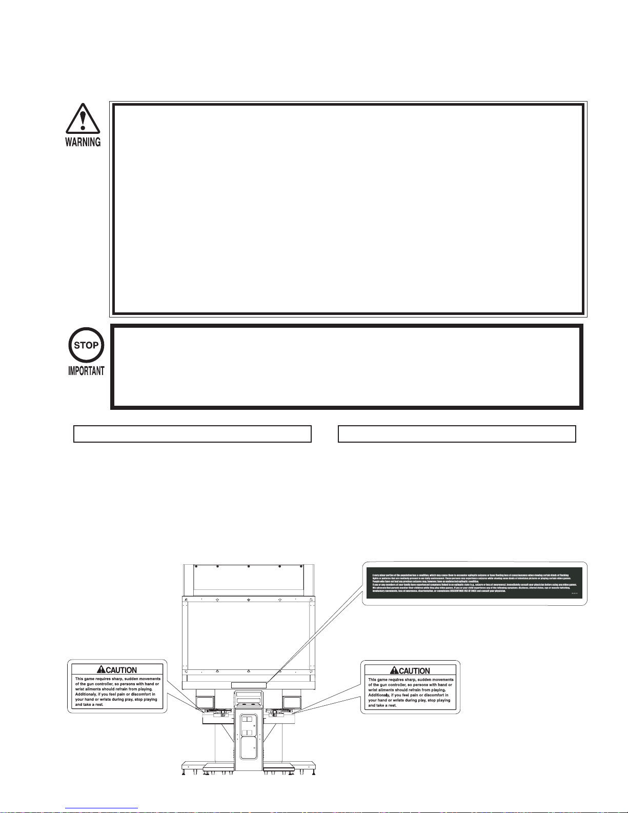
CONCERNING THE STICKER DISPLAY
This SEGA product has stickers attached describing the product manufacture No. (Serial No.) and Electrical Specifi cations. It also has a Sticker
describing where to contact for repair and for purchasing parts.
When inquiring about or asking for repairs, mention the Serial No. and
Name of Machine indicated on the Sticker. The Serial Number indicates the
product register. Identical machines could have different parts depending on
the date of production. Also, improvements and modifi cations might have
been made after the publication of this manual. In order to ensure you order
the correct parts, mention the Serial No. when contacting the applicable
places.
62”DX and 52”DX
*Picture is 62”DX
CONCERNING WARNING DISPLAYS
This SEGA product has warning displays on stickers, labels and/or printed instructions adhered/attached to or incorporated in the places where a potentially
hazardous situation could arise. The warning displays are intended for accident prevention for customers and for avoiding hazardous situations relating
to maintenance and servicing work. Some portions of the cabinet contain high
voltage and may cause accidents if touched. When performing maintenance,
be very careful of the warning displays. It is especially important that any
complex repair and replacement work not mentioned herein should be performed by those technical personnel who have knowledge of electricity and
technical expertise. In order to prevent accidents, caution any customer
ignoring the warnings to stop immediately.
EPILEPSY CAUTION STICKER
Part#: 99-30-014
CAUTION STICKER FOR GUN
HOD4 (2)
Part#: 515-30-215
1
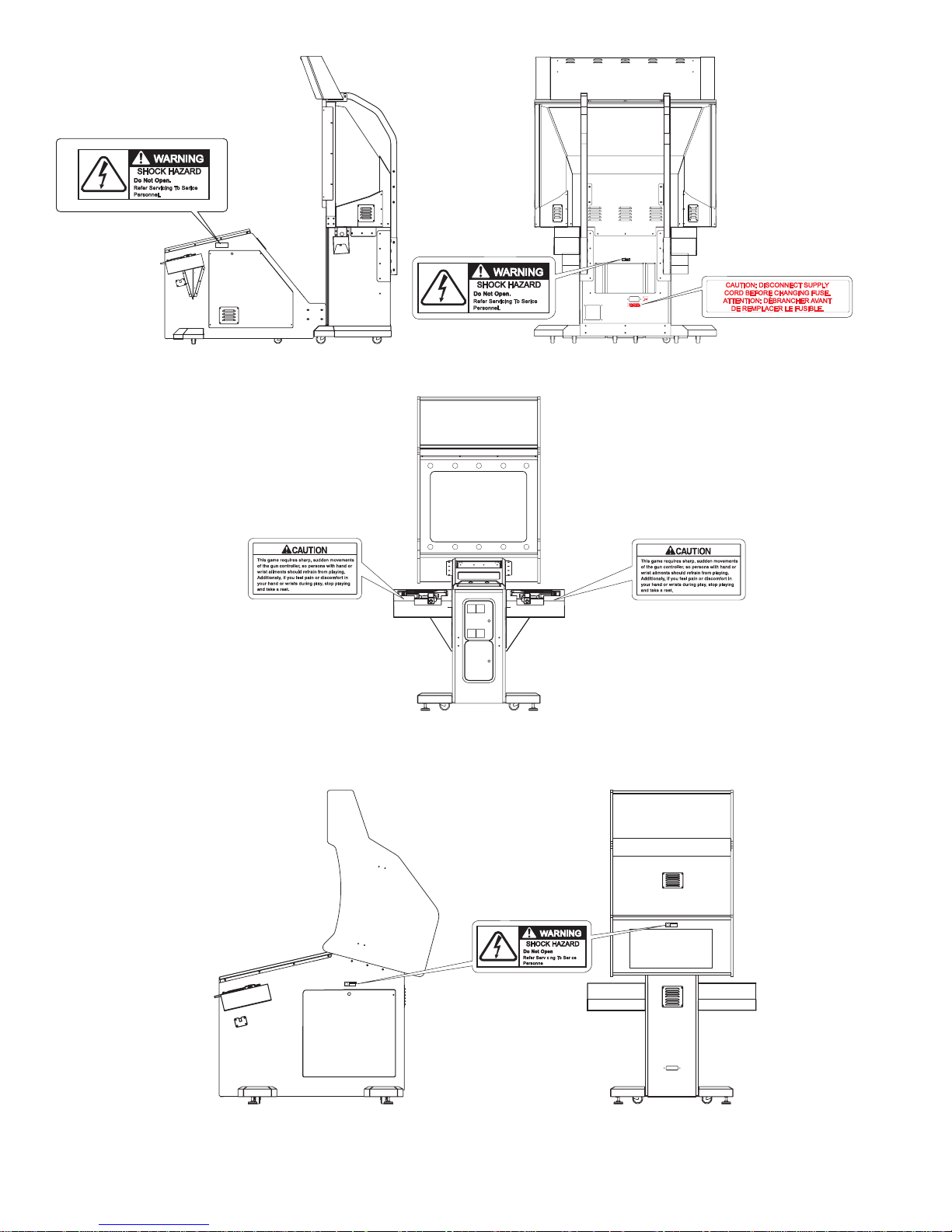
*Both side
29”STD
CAUTION STICKER FOR GUN
HOD4 (2)
Part#: 515-30-215
2
2. PRECAUTIONS REGARDING INSTALLATION LOCATION
This product is an indoor game machine. Do not install it outside. Even indoors, avoid installing in places mentioned below so as
not to cause a fi re, electric shock, injury and/or malfunction.
- Places subject to rain or water leakage, or places subject to high humidity in the proximity of an indoor swimming pool and or
shower, etc.
- Places subject to direct sunlight, or places subject to high temperatures in the proximity of heating units, etc.
- Places fi lled with infl ammable gas or vicinity of highly infl ammable/volatile chemicals or hazardous matter.
- Dusty places.
- Sloped surfaces.
- Places subject to any type of violent impact.
- Vicinity of anti-disaster facilities such as fi re exits and fi re extinguishers.
- The operating (ambient) temperature range is from 41F
2-1 LIMITATIONS OF USAGE
Be sure to check the Electrical Specifi cations. Ensure that this product is compatible with the location’s power supply, voltage and frequency
requirements. A plate describing Electrical Specifi cations is attached to the product. Non-compliance with the Electrical Specifi cations can
cause a fi re and electric shock.
This product requires a breaker and earth mechanism as part of the location facilities. Using the product without these can cause a fi re and
electric shock.
Ensure that the indoor wiring for the power supply is rated at 5A or higher (AC single phase 100V~120V area), and 7A or higher (AC
220V~240V area). Non-compliance with the Electrical Specifi cations can cause a fi re and electric shock.
Be sure to use an independent power supply equipped with a surge-suppressor. Using a power supply without a surge-suppressor can cause
an outbreak of fi re if a power surge occurs.
Putting many loads on one electrical outlet can cause generation of heat and a fi re resulting from overload.
When using an extension cord, ensure that the cord is rated at 15A or higher (AC 100V~120V area) and 7A or higher (AC 220V~240V
area). Using a cord rated lower than the specifi ed rating can cause a fi re and electric shock.
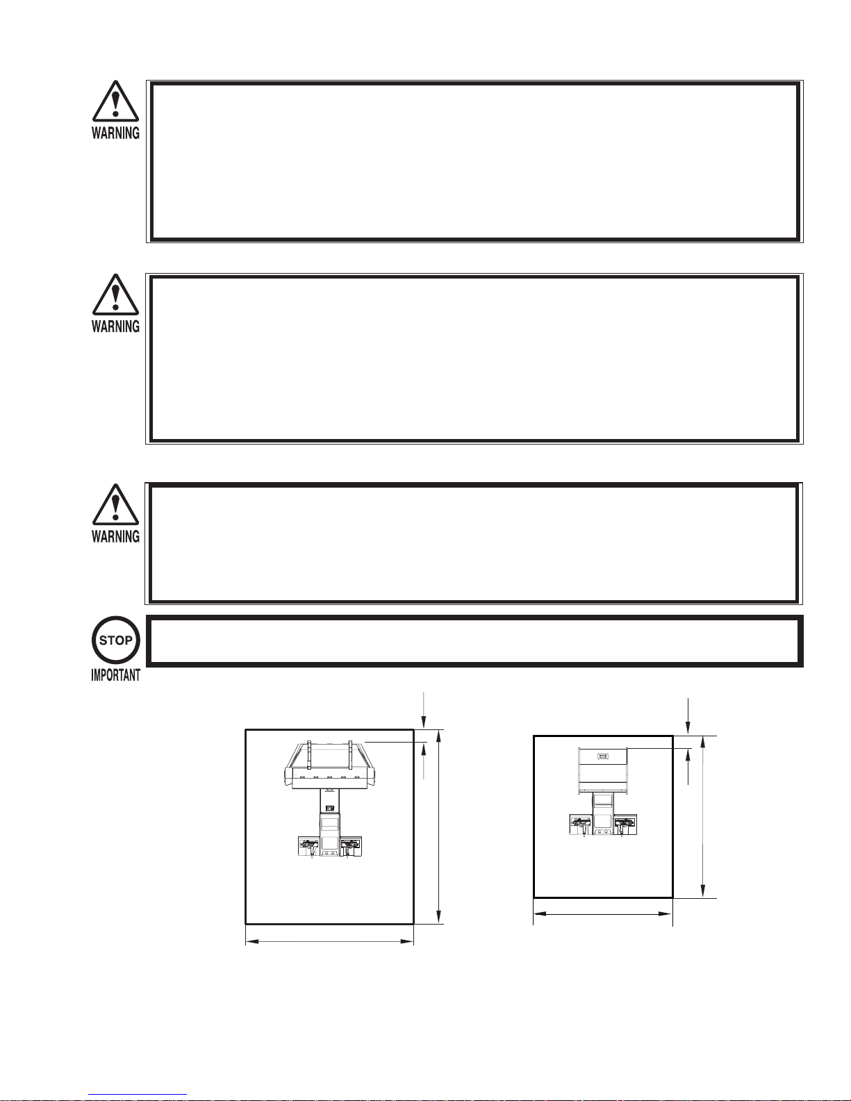
2-2 OPERATION AREA
o
to 86Fo.
For the operation of this machine, secure a minimum area of 2.6m (8.6F) (W) x 3.0m (9.8F) (D) for 52”/62”DX cabinets, 2.14m (7F) (W) x
2.5m (8.2F) (D) for 29”STD cabinet. In order to prevent injury resulting from falls/accidents during game play, be sure to secure the minimum area for operation.
Be sure to provide suffi cient space (200mm = 7.9” minimum) so as to allow this product’s ventilation fan to function effi ciently. To avoid
machine malfunctions or fi res, do not place any obstacles near the ventilation opening.
Do not allow objects to block the ventilation ports. It can cause generation of heat and a fi re.
SEGA shall not be held responsible for damage or compensation for damage to a third party, resulting from the failure to observe this
instruction.
In order to transport the machine into a building, the minimum necessary dimensions of the opening (of doors, etc.) are 1.3m (4.3F) [W] and
1.9m (6.2F) [H].
Ventilation space:
200 mm (7.9") minimum
3000 mm
(9.8F)
Ventilation space:
200 mm (7.9") minimum
2500 mm
(8.2F)
29"STD
52"/62"DX
*Picture is 62"DX
2600 mm (8.6F)
FIG.2
2134 mm (7F)
Electricity Comsumption: 52”/62”DX
960W, 8A (AC 120V, 60Hz)
Electricity Comsumption: 29”STD
600W, 5A (AC120V, 60Hz)
3
3. PRECAUTIONS REGARDING PRODUCT OPERATION
3-1 BEFORE OPERATION
To avoid injury and trouble, be sure to pay attention to the behavior of visitors and players.
In order to avoid accidents, check the following before starting the operation:
- To ensure maximum safety for the players and the customers, ensure that where the product is operated has suffi cient lighting to allow any
warnings to be read. Operation under insuffi cient lighting can cause players to bump into each other, causing trouble between customers.
- Be sure to perform appropriate adjustment of the monitor (projector). Do not leave the machine operating with monitor fl ickering or
malfunctioning. Failure to observe this can have a bad infl uence upon the players’ or the customers’ physical condition.
- It is suggested to ensure a space for players who feel sick while playing the game to take a rest.
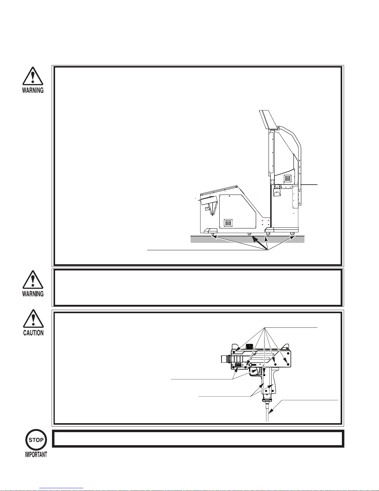
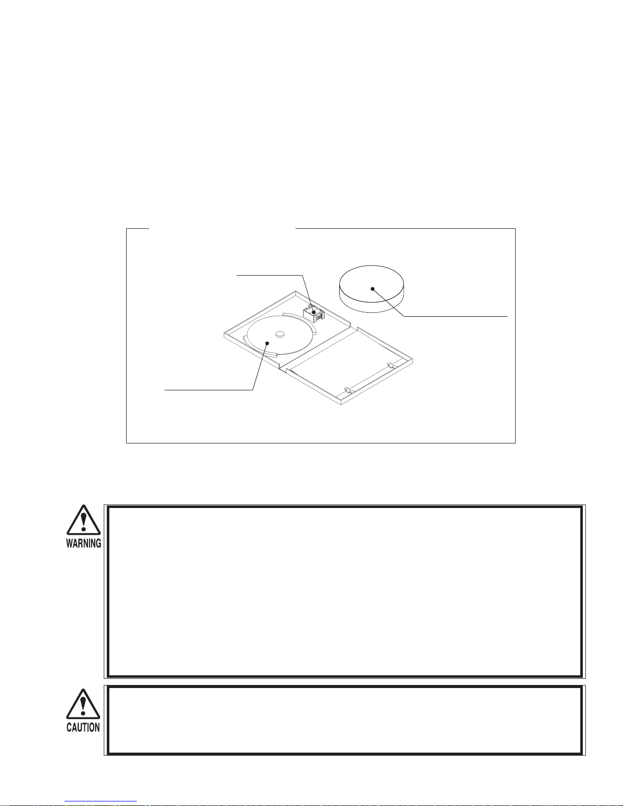
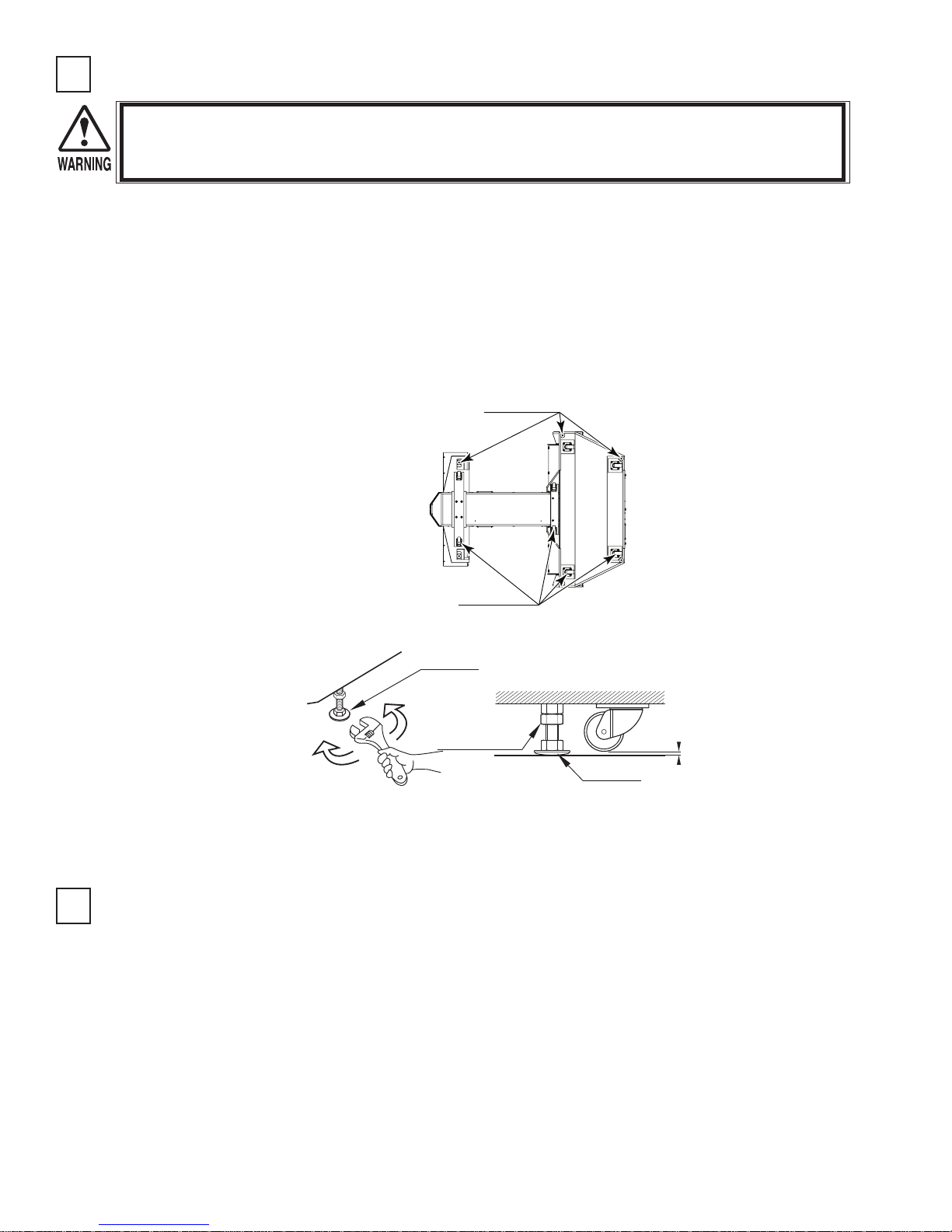
- Check if all of the adjusters are in contact with the surface.
- If they are not, the cabinet can move and cause an accident.
NOTE: PICTURE IS 62"DX CABINET
Ensure that all the adjusters are in contact with the floor.
- Do not put any heavy items on this product. Placing heavy items on the product can cause accidents or parts damage.
- Do not climb on the product. Climbing on the product can cause accidents. To check the top portion of the product, use a step.
- To avoid electric shock, check that no door & cover parts are damaged or missing.
- To avoid electric shock, short circuit and or parts damage, do not put the following items on or in the periphery of the product.
- Flower vases, fl owerpots, cups, water tanks, cosmetics, and receptacles/containers/vessels containing chemicals or water.
To avoid injury, be sure to provide suffi cient space
by considering the crowd situation at the installation
location. Insuffi cient installation
space can cause customers to bump into each other,
causing trouble.
Every day when cleaning the Control Unit (Gun),
inspect the gun and make sure that there are no
scratches or cracks in the surface, and
that the fastening screws are not loose. If the game is
played with scratches, cracks or loose screws it can
cause injuries to the player or
to people nearby.
Ensure that the trigger and buttons
are functioning properly.
Ensure that the casing is free
of scratches and cracks
Ensure that the screws are
not loose and are all present.
Ensure that all connecting wires
are not damaged.
Players directly hold the controller with their bare hands so it is recommended that the wet towels (paper towels) be provided.
4
3-2 DURING OPERATION (PAYING ATTENTION TO CUSTOMERS)
To avoid injury and trouble, be sure to pay attention to the behavior of visitors and players.
To avoid injury and accidents, those who fall under the following categories should refrain from playing the game.
- Those who need assistance such as the use of an apparatus when walking.
- Those who have high blood pressure or a heart problem.
- Those who have experienced muscle convulsion or loss of consciousness when playing video games, etc.
- Those who have neck or spinal cord problems.
- Intoxicated persons.
- Pregnant women or those who could be pregnant.
- Persons susceptible to motion sickness.
- Persons who disregard the product’s warning displays.
Even players who have never been adversely affected by light stimulus might experience dizziness or headache depending on their physical
condition when playing the game. Small children are especially likely to experience these symptoms. Caution guardians of small children to
keep watch on their children during play.
It is suggested to provide a space for players who feel sick while playing the game to take a rest.
Instruct those who feel sick during play to have a medical examination.
To avoid injury from falls and electric shocks due to spilled drinks, instruct the player not to place heavy items or drinks on the product.
To avoid electric shocks and short circuits, do not allow customers to put hands and fi ngers or extraneous matter in the openings of the
product or small openings in or around the doors.
To avoid falls and resulting injury, immediately stop the customer from leaning against or climbing on the product, etc.
To avoid electric shocks and short circuits, do not allow customers to unplug the power plug.
Be sure to instruct the adult responsible for their children to watch them. Children cannot sense danger. Approaching the player during
play may result in accidental contact, collisions or falls. If the gun is pulled from the gun holder and dropped on the head, it may cause
injury.
Caution the player not to wrap the gun cord around his/her wrist or neck, as this can lead to serious injury.
Immediately stop such violent acts as hitting and kicking the product.
Such violent acts can cause parts damage or cause the cabinet to fall over, resulting in injury.
Immediately stop users from leaning or sitting on the gun holder. Such acts can lead to injury or damage to parts or the shape of the cabinet.
Immediately stop users from swinging or reloading the Control Unit (Gun) in a violent manner. Such acts may hurt the user or other
people around them.
Playing too close to the cabinet may cause the Control Unit (Gun) to hit the cabinet and cause damage. Make sure that players understand
to play at a safe distance from the cabinet.
Make sure that players understand not to stand too close together when playing a two player game. Swinging the Control Unit (Gun)
could lead to a player getting hit and may cause injury.
Make sure that players understand to hold the Control Unit (Gun) fi rmly during play. Dropping the Control Unit (Gun) could cause damage
to it or injure the player.
Larger rings and other such accessories may lead to injury to fi ngers during play. Make sure that players understand to remove any
accessories prior to playing the game that may cause such accidents.
Make sure that players understand that more than one person is not allowed to play with a single Control Unit (Gun). Such play could lead
to various injuries.
Make sure to avoid disturbing customers when moving/removing the machine from its current location.
The Control Units (Guns) for use on 1P side (left side) and 2P side (right side) are different. Ensure that players do not confuse
the right and left side guns when starting play.
5
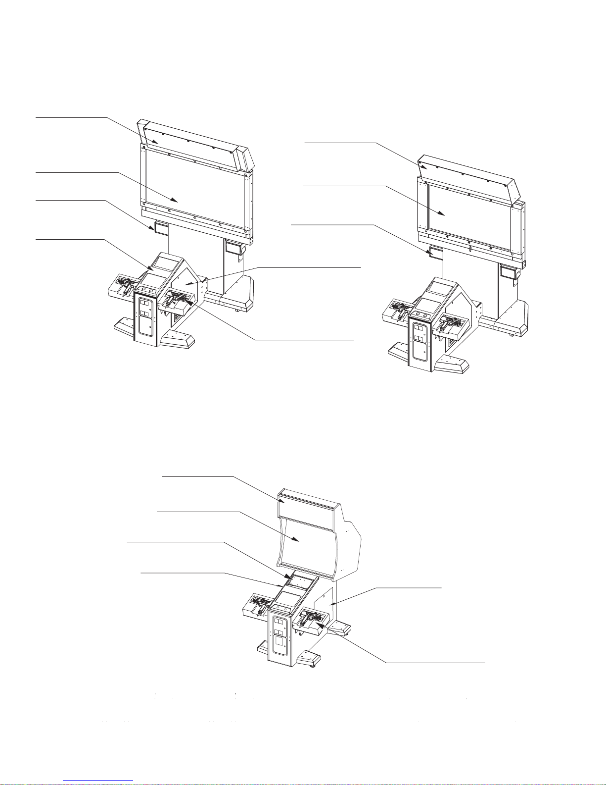
4. PART DESCRIPTIONS
BILL BOARD
62” DLP PROJECTOR
SPEAKER (L)
SPEAKER (R) > Otehr
side
CONTROL PANEL
BILL BOARD
52” DLP PROJECTOR
SPEAKER (L)
SPEAKER (R) > Otehr
side
SIDE DOOR (R)
SIDE DOOR (L)
> Other side
62”DX
Dimensions:
94”(H) x 60”(W) x 76”(D)
MARQUEE
29” CRT MONITOR 31K
SPEAKER (L) and (R)
CONTROL PANEL
CONTROL UNIT (GUN)
52”DX
Dimensions:
89”(H) x 60”(W) x 76”(D)
SIDE DOOR
29”STD
6
CONTROL UNIT (GUN)
Dimensions:
77”(H) x 41.5”(W) x 55”(D)
5. ACCESSORIES
Confi rm that the accessories listed in the table below are present when setting up the product. Accessories marked “Spare” in
the note column are consumable items but included as spares.
62”/52”DX
- OWNER’S MANUAL (1)
- WRENCH SET
T-25 TORX 10-24/10-32
T-15 TORX 8-32
T-40 TORX 5/16-18
T-27 TORX 1/4-20)
- DVD SOFTWARE KIT(1)
DVD SOFTWARE KIT (1)
DVD-ROM DISC (1)
29”STD
- OWNER’S MANUAL (1)
- WRENCH SET
- DVD SOFTWARE KIT (1)
KEY CHIP (1)
CUSHION SPONGE
601-11137 (1)
DVD-ROM Disc Protector
NOTE: When you order the DVD-ROM disc only, specify the part number 610-0726-0003 (DVD SOFT HDF).
NOTE: Do not use DVD SOFTWARE KIT when start operation because game software already installed when manufactured.
6. ASSEMBLY AND INSTALLATION
Perform assembly work by following the procedure herein stated. Failure to comply with the instructions can cause electric shock.
Perform assembling as per this manual. Since this is a complex machine, incorrect assembling can cause an electric shock, machine damage
and/or improper functioning as per specifi ed performance.
When assembling, be sure to use plural persons. Depending on the assembly work, there are some cases in which working by one person
alone can cause personal injury or parts damage.
Ensure that connectors are accurately connected. Incomplete connections can cause electric shock.
Be careful not to damage the wires. Damaged wires may cause electric shock or short circuit or present a risk of fi re.
Do not carelessly push the projector. Pushing the projector carelessly can cause the projector to fall down.
This work should be carried out by the site maintenance personnel or other qualifi ed professionals. Performing work by non-technical per-
sonnel can cause a severe accident such as electric shock. Failing to comply with this instruction can cause a severe accident such as electric
shock to the player during operation.
Provide suffi cient space so that assembling can be performed. Assembling in places that are narrow or have a low ceiling may cause dif-
fi culty to perform the work and can cause an accident.
To perform work safely and avoid serious accidents such as the cabinet falling down, do not perform work in places where elevation differs,
a ditch, or slope exist.
Do not use this product with connectors other than those that were connected and used with the Game Board at the time of shipping. Do not
carelessly connect wires to connectors that were not used at the time of shipping, as this may cause overheating, smoke or fi re damage.
Handle molded parts with care. Excessive weight or pressure may cause them to break and the broken pieces may cause injury.
To perform work safely and securely, be sure to prepare a stepladder which is in a secure and stable condition. Performing work without
using the stepladder can cause accidents such as falling down.
Check the tags on the wire carefully before connecting the DVD wire connectors. Once you have the correct connector be sure to insert it in
the correct direction and angle. Attempting to force the incorrect connectors together or connecting them at the incorrect angle may
damage the connectors and create a fi re risk or risk of burns.
7
Be very careful when handling the projector screen. The screen is easily damaged but cannot be repaired. If damaged the entire screen must be
replaced.
When carrying out the assembling and installation, follow the following 8-item sequence.
1 INSTALLING MONITOR (52”/62”DX)
2 SECURING IN PLACE
3 POWERING ON
4 ASSEMBLY CHECK
Tools and Implements Required for the Work
- Phillips screwdriver (for M4 screws)
- Wrench (Spanner) with a jaw width of 1” (24.5 mm)
1” (24.5mm)
- Socket wrench set
- Key
- Torx wrench set
8
INSTALLING MONITOR, 52"/62"DX
1
This game is provided with either a 52 or
62 monitor dependant upon the model
purchased. At least 2 people are required
to perform the installation. The footnotes
you see, refer to parts shown on the last
page of the instructions.
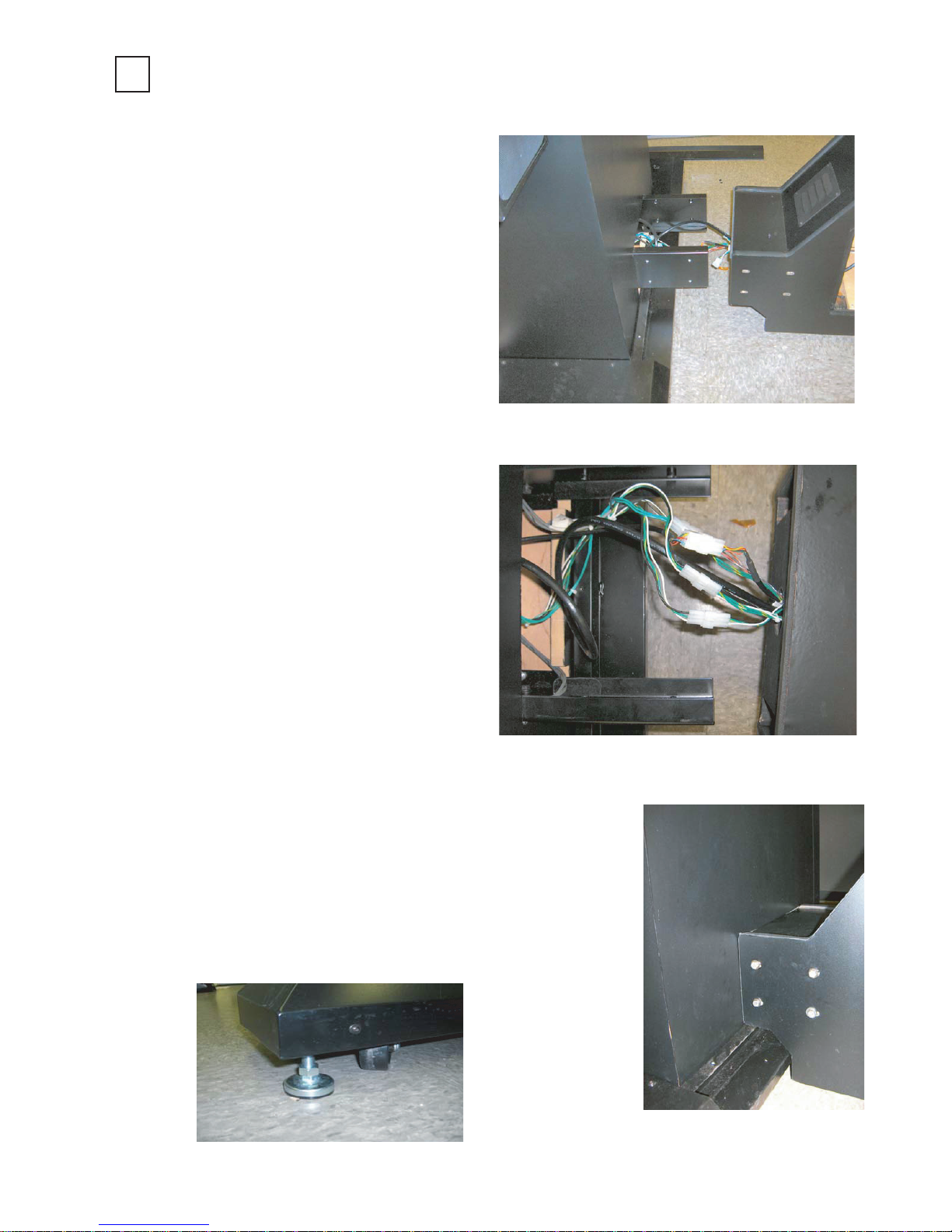
Start the assembly by joining the front
and rear sections of the game. (Figure 1)
When the two sections are aligned, feed
the video cable through the cabinet from
the game board to the rear cabinet then
up through the hole in the platform where
the monitor will rest.. Next connect the
harnesses extending from the front
cabinet to the rear cabinet as shown in
Figure 2.
When the harnesses are connected, join
the two halves together by inserting the
U-Brackets of the rear into the slots of
the front cabinet. The front cabinet may
require lifting to properly align the
brackets with the slots.
After the halves are joined together,
install the 8 tamper proof bolts and
washers, 4 in each side of the cabinet to
secure the 2 halves. (Figure 3) Note-
hardware is generally provided in the
location where it is to be installed. (Also
check parts bag)
Once secured, lower all the leg levelers
to the floor to help prevent the game from
moving as additional operations are
performed. Figure 4
(52”LG and 62”ZENITHI)
Figure 1
Figure 2
Figure 4
Figure 3
9
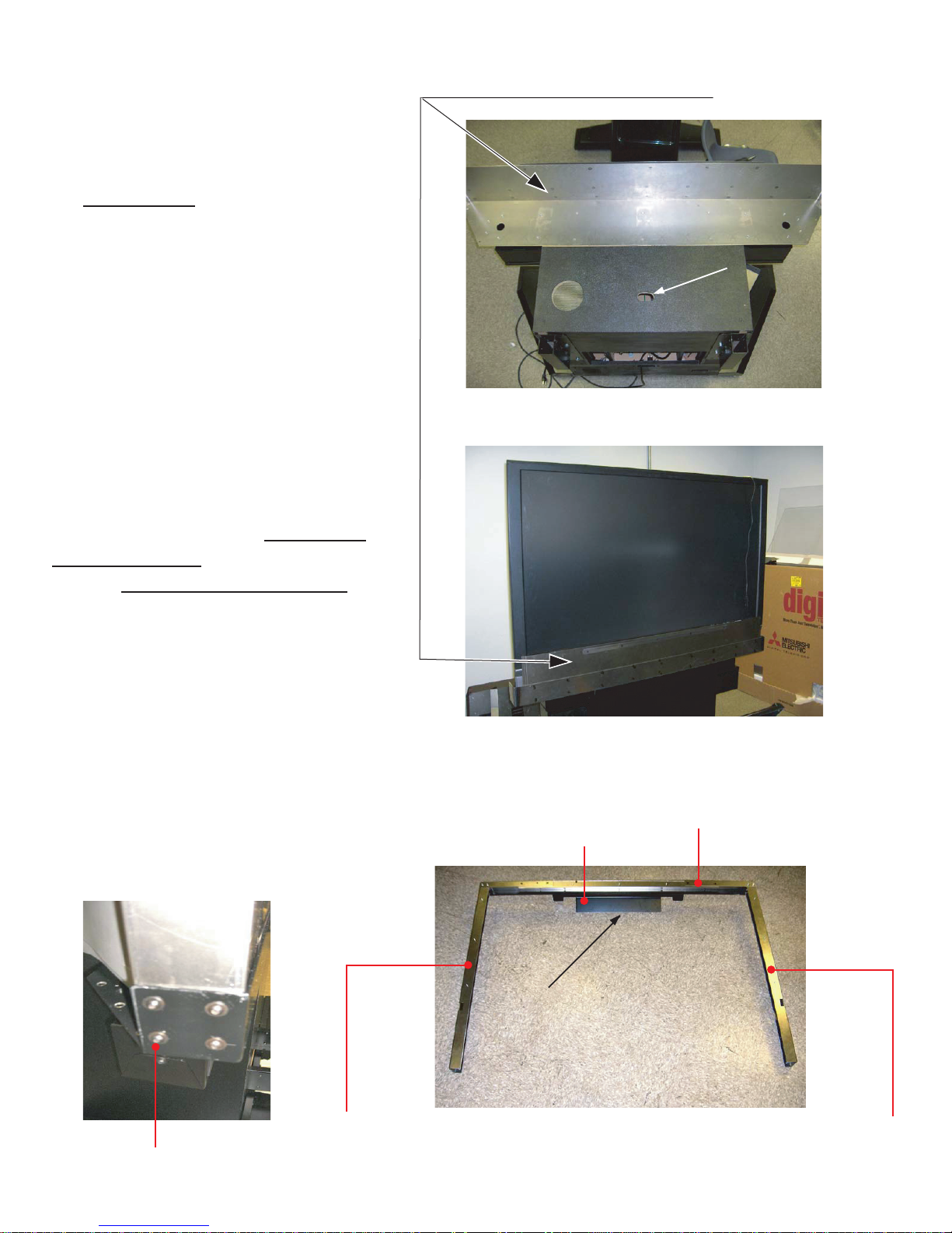
After the game is joined and stabilized,
using two people, place the monitor on
top of the platform shown (Figure 5) with
the screen side of the monitor up against
the metal bracket
. The access hole
1
shown, is used for the line cord from the
monitor and the video cable that
connects the monitor to the game board.
When the monitor is on the platform
(Figure 6) feed the line cord and video
cable through the access hole. Connect
the line cord to the receptacle provided
on the filter board below and connect the
video harness to the appropriate
connector .When connecting the video
cable, use position RGB on the 52
monitor and HDMI 1 on the 62 monitor.
Next, assemble the three monitor side
protector brackets2 as shown in Figure 7.
Add the weldment marquee support
.
3
When completed, slide the assembly
over the monitor with the flange of the
support facing the rear and secure the
assembly to the base bracket on the
1
pedestal using the four
/4-20 X 1/2
tamper proof bolts on each side (Figure
8). Note: the appearance of the various
monitor brackets varies slightly from the
62 inch model to the 52 inch model
monitor.
Figure 8A
1: Weldment, front monitor support
Part#: S254-032-000 (52"), S255-015-00 (62")
Access Hole
Figure 5
Figure 6
3: Weldment, marquee support
Part#: S254-045-000 (52")
S255-026-000 (62")
2-3: Weldment, monitor retainer cap
Part#: S254-042-000 (52")
S255-022-000 (62")
1/4-20 1/2" Tamper proof bolts (4)
10
2-1: Bracket monitor retainer Left
Part#: S254-138-00L (52")
S255-105-00L (62")
Flange
Figure 7
2-2: Bracket monitor retainer Right
Part#: S254-138-00R (52")
S255-105-00R (62")
5: Bracket, Glass channel
Part#: S254-142-000 (52"/62")
4: Plexiglass shield
Part#: S254-502-000 (52")
S255-500-000 (62")
7: Tube, Marquee struts
Part#: S254-124-000 (52"/62")
Figure 8A
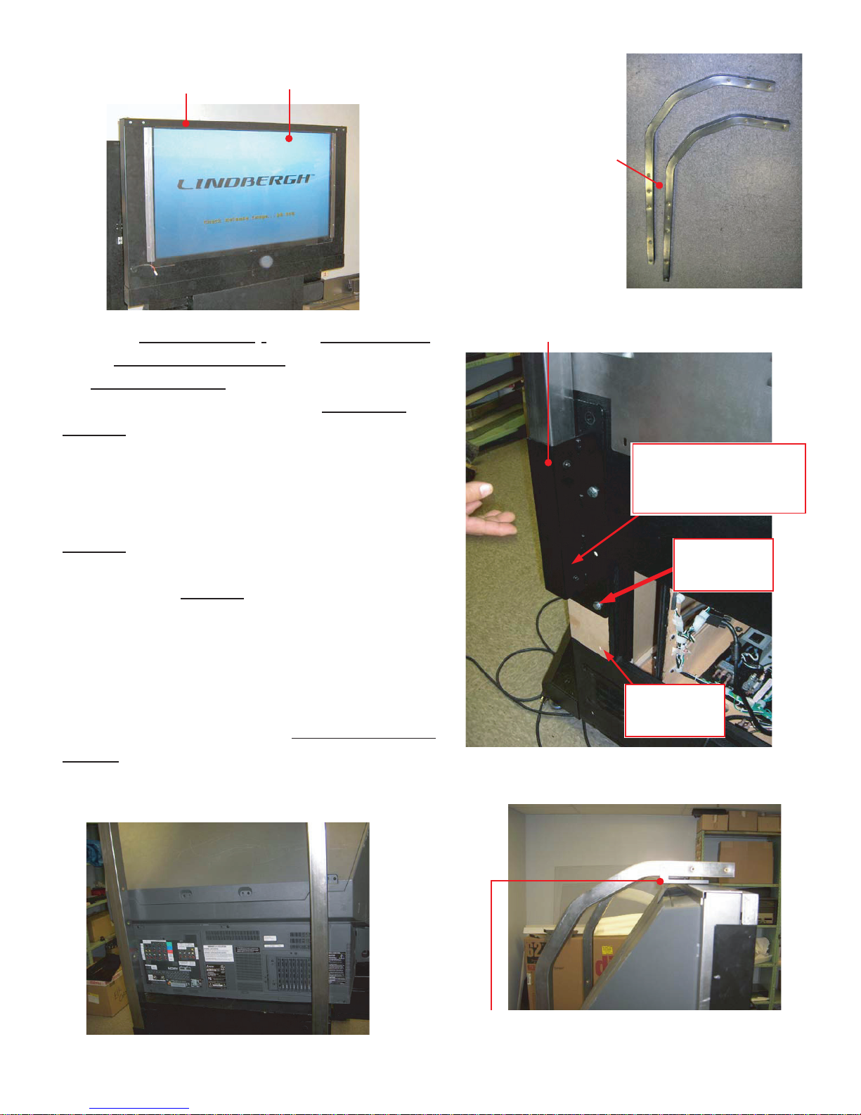
Install the Plexiglas shield
on the monitor side protectors
the rectangular tubing
and its retaining strips
4
(Figure 8A). Locate
6
(Figure 9) in the packaging
7
5
and install them in each of the two rectangular
brackets8 in the rear of the game (Figure 10) using
1
/4-20 X 3/4 tamper-proof bolts with washers
the
and lock washers. Warning: The tube with the
cable inside should be mounted on the players
right. Note: when using the 62 monitor that the
brackets
holding the tubes are in the upper
8
position as shown in Figure 10. When used with a
52 monitor the brackets
are placed in the lower
8
position as indicated by the light patch on the
sample cabinet shown. When installed, the tubing
should appear as in Figures 11 and 12.
The upper part of the tubes should arc over the top
of the monitor in preparation for the marquee
installation. Next, connect the weldment marquee
support
in Figure 12 Using two
on the monitor to the two tubes as shown
3
1
/4-20 X 3/4 tamper-proof
bolts with washers and lock washers per tube.
8: Weldment, Marquee support L/R
Part#: S254-028-00L, S254-028-00R (52"/62")
The cable should feed
through the slot in the
cabinet
Lower
52"Monitor
Figure 10
Figure 9
Upper
62"Monitor
Figure 11
3: Weldment, marquee support
Part#: S254-045-000 (52")
S255-026-000 (62")
Figure 12
11
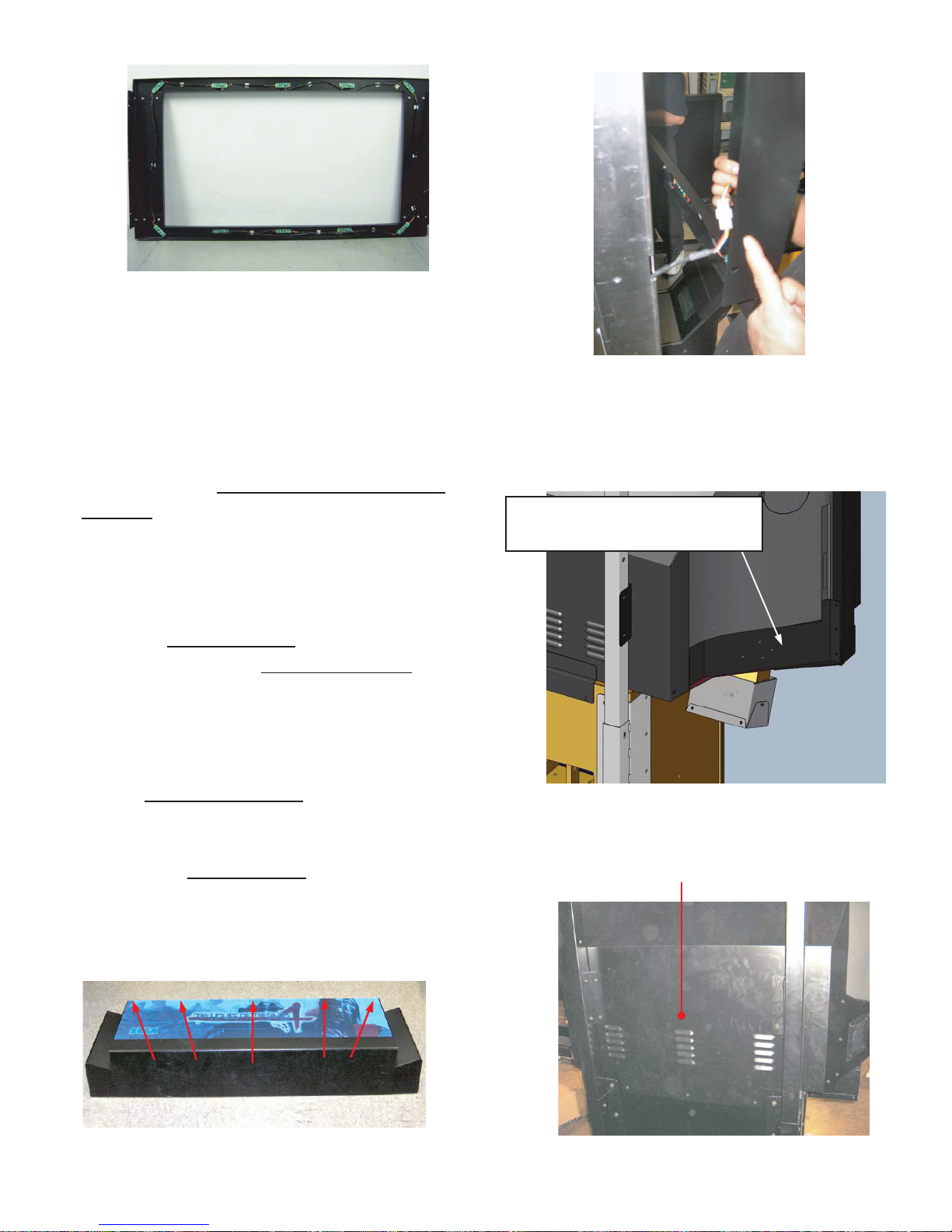
Figure 13
Connect the Mask assembly (Figure 13) to the
monitor using the attached hardware. Be careful
to connect the plug (Figure 14) on the left side
of the mask prior to securing the mask
assembly to the monitor.
Next, attach the left and right monitor corner
brackets10 (Figure 15) using the hardware
1
provided 10-32 X
washers and lock washers (Note: the brackets
shown, are for the 62 monitor, the appearance
of these brackets is different for the 52 model.)
When the corner brackets
both sides, install the monitor rear cover
tubes using 1/4-20 X
lock washers and secure the cover to the base
cabinet using 8-32 X 1
washers and lock washers (Figure 16). Again,
the 62 monitor cover plate
model is slightly different in appearance .
The next step is the marquee installation.
Remove the marquee plate
marquee assembly by extracting the 5 screws
and decorative washers on the top of the
assembly. (Figure 17).
/2 tamper-proof screws,
are mounted on
10
to the
3
/4 bolts washers and
1
/4 tamper-proof screws,
is shown, the 52
11
(artwork) from the
12
11
10: 52" Bracket side trim L/R
Part#: S254-158-00L, S254-158-00R (52")
10: 62" Weldment, Cover side screened Left/Right
Part#: S255-019-00L, S255-019-00R (62")
10 = For 62”DLP, Zenith:
Part#: S260-103-00L (Left)
Part#: S260-103-00R (Right)
11: Weldment, Rear monitor
Part#: S254-035-000 (52")
Part#: S255-018-000 (62")
Figure 14
Figure 15
Figure 15
Figure 17
12
Figure 16
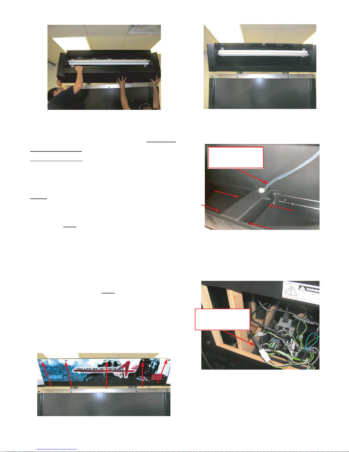
Figure 18 Figure 19
Using at least two people and step ladders,
guide the marquee assembly onto the weldment
marquee support3, by inserting the two
rectangular tubes
marquee (Figure 18). When the assembly is
fully seated, the mounting holes inside the
marquee should align with the holes on the
tubes
. (Figures 19 &20). Install 1/4 -20X 3/4
7
bolts and flat washers and lock washers to
secure each side of the marquee to its
respective tube
four in each tube.
When the marquee is secured, feed the
fluorescent power cord up through the hole on
the top of the tube and connect to the 3 pin
housing on the fluorescent fixture s harness
(Figure 20). Next, connect the housing located
on the lower end of the tube
in the lower cabinet (Figure 21).
Remove the plastic film from the marquee plate
and re-install the plate in the assembly using the
screws and decorative washers you removed
earlier. (Figure 22)
through the rear of the
7
(Figure 20) Eight bolts total,
7
, to the 3 pin plug
7
Fluorescent
fixture's harness
Figure 20
Fluorescent
fixture's harness
Figure 22
Figure 21
13
SECURING IN PLACE
2
Make sure that all the adjusters are resting on the fl oor. The cabinet may move and cause an accident if the adjusters are not laid out
properly.
Leave at least 8” of space behind the projector for air exchange. The air vent is on the back of the machine. This air vent must never be
blocked by anything. If it is blocked heat may build up creating the risk of fi re. It may also speed up damage and deterioration of parts.
The cabinet is equipped with 8 casters (4 for DLP Base and 4 for Cabinet) and 6 adjusters (4 for DLP Base and 2 for Cabinet).
After deciding on a location, bring the adjusters into direct contact with the ground and adjust the cabinet so that it is completely level. If the fl oor is level, the
machine should be level with the casters about 5 millimeters from the fl oor.
1) Move the cabinet to the desired location. Make sure there is space in the back for air to fl ow.
2) Bring the adjusters into direct contact with the fl oor. Use a wrench to align the height of the
adjusters until the cabinet is perfectly level.
3) After making the fi nal adjustments, fi x the adjuster height by tightening up the adjuster nuts.
FIG. 6.4a Bottom View
FIG. 6.4b Aligning the adjusters
ADJUSTER
ADJUSTER (6)
CASTER (8)
Fasten the nuts in
an upward direction.
CASTER
Approx. 5mm
ADJUSTER
POWERING ON
3
Turn the main switch on the AC unit ON to supply power.
As soon as the power is supplied the fl uorescent lamps inside the billboard and the cold-cathode tubes inside the lighting unit will come on. A few seconds
later the LINDBERGH start-up screen will be displayed and then the Advertisement Mode (Attract Mode) will start, which displays a demo of the game
and score rankings. It takes approximately 3 minutes to reach the Attract Mode. During Attract Mode sound will be emitted from the left and right speakers
beneath the projector. However if sound during Attract Mode is turned off in TEST Mode, no sound will be emitted. Even if the product’s power is turned off
the number of credits played, ranking data, game diffi culty and other settings and bookkeeping data will all be saved. The number of incomplete credits (coins
inserted that did not equal a credit) and the bonus adder count data will not be saved.
14
ASSEMBLY CHECK
4
Use Test Mode to check that the product has been assembled correctly and that the game board, other connected boards and all output devices are working correctly. Perform this test in Test Mode as follows. See “9-2 System Test Mode” for tests (1) to (4) below and “9-3 Game Test Mode” for test (5) to (7).
(1) Information Display Screen
Selecting SYSTEM INFORMATION, STORAGE INFORMATION or JVS TEST from the SYSTEM TEST Mode menu screen will displayed system information, game information and information concerning the JVS I/O board attached to the LINDBERGH board. If all information is displayed correctly then the
LINDBERGH board is running smoothly.
(2) JVS Input Test Screen
Selecting INPUT TEST on the JVS TEST Screen will display input data for the JVS I/O board. For this product this is the screen to test the coin switches. Insert
a coin to perform a test. If the display nest to the switch changes the switch and connections are working correctly.
(3) Monitor Test Screen
Selecting MONITOR TEST on the SYSTEM TEST Mode menu screen will display a screen that allows the monitor output to be tested. The projector comes
adjusted from the factory but still use this TEST Screen to make sure that further adjustment is not required. If required, see chapter 11 for information on
adjusting the projector.
(4) Speaker Test Screen
Selecting SPEAKER TEST from the SYSTEM TEST Mode menu screen will display a screen that allows the speaker output to be tested. The speakers attached
to the machine will output a test sound. Use this to check that all speakers are outputting correctly.
(5) Input Test
Selecting INPUT TEST from the GAME TEST Mode menu screen will display a
screen that allows input devices to be tested. Press each switch to check that each
is working. If the display next to the input device changes to on “ON” or the values
displayed change smoothly then that input device and all connections
with it are working correctly.
(6) Output Test
Selecting OUTPUT TEST from the GAME TEST Mode menu screen will display
a screen that allows output devices to be tested. Operate the lamps and other output
devices and check that they are all working correctly.
INPUT TEST
START OFF OFF
GUN TRIGGER OFF OFF
GUN BUTTON OFF OFF
GUN SPEED X 7f 7f
GUN SPEED Y 7f 7f
GUN X 00 00
GUN Y
SCREEN IN OUT OUT
SERVICE OFF
TEST
PRESS TEST
START1 LAMP OFF
START2 LAMP OFF
-> EXIT
PLAYER1 PLAYER2
00 00
OFF
AND SERVICE TO EXIT
OUTPUT TEST
(7) Calibration Check and Speed Check
Prior to letting customers use the game you must play a game and make sure that
everything is operating correctly. Although adjusted prior to leaving the factory
incidents in transit may have affected these settings and so check to make sure that
adjustment is not required.
You should perform the above checks once a month. However (7) should be performed at least once a week.
SELECT WITH SERVICE AND PRESS TEST
GUN MARK CHECK
+ OUT OF SCREEN P1 + + OUT OF SCREEN P2 +
PRESS TEST TO EXIT
15
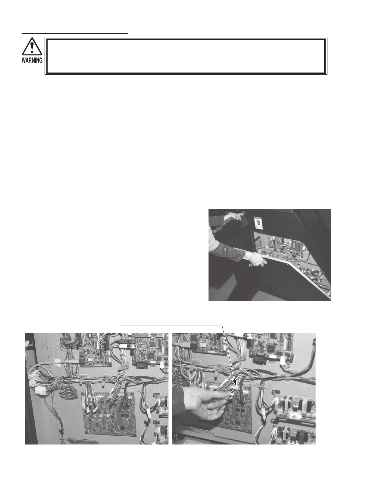
Interference Prevention Wiring
In order to prevent electric shock and short circuit hazards, be sure to turn power off before performing work.
Be careful not to damage the wires. Damaged wires may cause electric shock or short circuit or present a fi re risk.
Do not expose the IC board, etc. unless absolutely necessary. Failure to observe this can cause electric shock hazard or malfunctioning.
This work should be performed by the site maintenance personnel or other qualifi ed professionals. Performing work by non-technical
personnel can cause a severe accident such as electric shock.
When the game machines of a same or similar type are installed side by side, their sensors may
interfere with each other. To reject the interference, follow the procedure below.
The following game machines employ a same or similar type of sensor. If interference happens
to the sensors, operation of the games may be mutually disturbed.
- THE HOUSE OF THE DEAD 2, U/R type, DX type and Super DX type
- DEATH CRIMSON, U/R type and DX type
- THE LOST WORLD, U/R type, DX type and Super DX type
- BRAVE FIRE FIGHTERS
- SAMBA DE AMIGO
- CONFIDENTIAL MISSION, U/R type and DX type
- SHAKATTO TAMBOURINE
- LUPIN THE 3RD THE SHOOTING, U/R type and DX type
- THE MAZE OF THE KINGS, U/R type and DX type
- THE HOUSE OF THE DEAD 3, U/R type and DX type
- VIRTUA COP 3, U/R type and DX type
- GHOST SQUAD, U/R type and DX type
- THE HOUSE OF THE DEAD 4
1) Turn the power off.
2) Undo the Screws and remove
the side door R from the cabinet.
3) The interference prevention wire is connected to the IC board inside the cabinet.
If multiple units of the same game are installed side by side, make sure that the game units
that are connected to the interference prevention wires are arranged so that they alternate
with the units that are not connected.
INTERFERENCE PREVENTION WIRING
HDF-60032
PHOTO. 6.9a
PHOTO. 6.9b PHOTO. 6.9c
16
 Loading...