


420-6770-01UK REV 0
SERVICE MANUAL
TWIN TYPE
Before using this product, read this SERVICE MANUAL carefully to understand the contents stated herein.
After reading this manual, be sure to keep it available nearby the product or somewhere convenient in
order to be able to refer to it whenever necessary.
Manufactured in the UK by

CONTENTS
1. BEFORE USING THIS PRODUCT.................................................................................................. 5
1.1. Inspections Immediately After Transporting The Product To The Location................................................6
2. INTRODUCTION TO THIS SERVICE MANUAL.............................................................................. 8
3. INSTALLATION AND SERVICE INSTRUCTIONS........................................................................... 9
3.1. Handling And Installation Precautions........................................................................................................9
3.2. Coin Handling...........................................................................................................................................11
3.3. Name Of Parts.........................................................................................................................................12
3.4. Accessories..............................................................................................................................................13
3.5. Shipping The Game Board and GD-ROM Drive......................................................................................14
3.5.1. How To Use The Triforce Carton Box...................................................................................14
3.6. Shipping The GD-ROM Drive...................................................................................................................15
3.7. Assembly Instructions ..............................................................................................................................16
3.7.1. Applying The Play Instructions.............................................................................................17
3.7.2. Assembling The Cockpit.......................................................................................................18
3.7.3. Securing In Place (Leg Adjuster Adjustment)........................................................................19
3.7.4. Billboard Installation.............................................................................................................21
3.7.5. Installing The AC Covers (Wire Covers )..............................................................................22
3.7.6. Coin Handling Installation.....................................................................................................23
3.7.6.1. Wiring Connections.......................................................................................................24
3.7.7. Communication Cables........................................................................................................25
3.7.8. Connection To The Power Supply........................................................................................26
3.7.9. Assembly Check ..................................................................................................................28
3.7.9.1. Memory Test.................................................................................................................28
3.7.9.2. Input Test......................................................................................................................29
3.7.9.3. Sound Test....................................................................................................................30
3.7.9.4. CRT Test ......................................................................................................................30
3.7.9.5. Output Test...................................................................................................................31
3.7.10. Moving The Machine........................................................................................................32
3.8. Fuses.......................................................................................................................................................33
3.9. Maintenance ............................................................................................................................................34
3.9.1. Removing The Control Panel ...............................................................................................35
3.9.1.1. Adjusting/Replacing The Volume...................................................................................36
3.9.1.2. Greasing .......................................................................................................................38
3.9.2. Steering Unit........................................................................................................................39
3.9.2.1. Adjusting And Replacing The Y-Axis VR .......................................................................40
3.9.2.2. Replacing The Microswitches........................................................................................46
3.9.2.3. Greasing .......................................................................................................................49
3.9.3. Card Reader/Writer Unit.......................................................................................................50
3.9.3.1. Setting Dedicated Cards................................................................................................50
3.9.3.2. Head Cleaning ..............................................................................................................52
3.9.3.3. Clearing Card Jams.......................................................................................................53
3.9.4. Accelerator & Brake.............................................................................................................54
3.9.4.1. Removing the Accelerator & Brake................................................................................54
3.9.4.2. Adjusting the V.R. .........................................................................................................55
3.9.4.3. Replacing the V.R. ........................................................................................................56
3.9.4.4. Greasing .......................................................................................................................56
3.10. Replacement Of Fluorescent Lamp And Other Lamps........................................................................57
3.10.1. Fluorescent Lamp Replacement .......................................................................................57
3.11. Cleaning The Cabinet Surfaces............................................................................................................58
3.12. Seat (Greasing To Seat Rail Portion)...................................................................................................58
3.13. Troubleshooting....................................................................................................................................59
3.13.1. Card Reader/Writer ..........................................................................................................59
3.13.2. Troubleshooting (When No Error Message Is Shown).......................................................62
3.14. Gameboard..........................................................................................................................................65
3.14.1. Removing The Board........................................................................................................65
3.14.2. Removing The GD-ROM Drive.........................................................................................66
3.14.3. Removing The Game Board (Triforce)..............................................................................68
3.14.4. Composition Of The Game Board.....................................................................................69
3.14.4.1. DIP SW Setting ............................................................................................................69
3.14.5. Replacing The Main Board Battery ...................................................................................70
3.14.6. Replacing The DIMM Board Battery Pack.........................................................................72
3.14.6.1. Warnings And Restrictions Concerning The Battery Pack.............................................72
2

3.14.7. Shipping The Game Board And GD-ROM Drive...............................................................75
3.14.7.1. How To Use The Triforce Carton Box ...........................................................................75
3.14.8. Machine Set Up................................................................................................................76
3.14.8.1. Network Play ................................................................................................................77
3.15. Periodic Check And Inspection.............................................................................................................82
4. HOW TO PLAY..............................................................................................................................83
4.1. Game Description....................................................................................................................................83
4.1.1. Game Outline.......................................................................................................................84
4.1.2. Game Mode.........................................................................................................................85
4.1.3. Playing the Game ................................................................................................................85
4.1.3.1. The Card Check Screen................................................................................................85
4.1.3.2. The F-Zero License Card Screen ..................................................................................86
4.1.3.3. The Name Entry Screen................................................................................................86
4.1.3.4. The License Card Screen..............................................................................................86
4.1.3.5. The Versus Screen........................................................................................................87
4.1.3.6. The Course Select Screen.............................................................................................88
4.1.3.7. The Machine Select Screen ..........................................................................................88
4.1.3.8. The Machine Setting Screen .........................................................................................89
4.1.3.9. Race .............................................................................................................................89
4.1.3.10. VS Result Screen .........................................................................................................90
4.1.3.11. Results Screen (Race Mode), Time Attack Ranking Screen (Time Attack Mode) .........90
4.1.3.12. The Pilot Points Screen ................................................................................................90
4.1.3.13. The Configuration Screen.............................................................................................91
4.1.3.14. Memory Card Screen ....................................................................................................91
4.1.3.15. The Password Screen...................................................................................................92
4.1.3.16. The Game Over Screen................................................................................................92
4.1.4. Other Warnings....................................................................................................................93
4.1.4.1. Error Display.................................................................................................................93
4.1.4.2. Secret Codes ................................................................................................................93
5. MAINTENANCE INSTRUCTIONS..................................................................................................94
5.1. Explanation Of Test And Data Display.....................................................................................................94
5.1.1. VTS Assembly .....................................................................................................................95
5.2. System Test Mode...................................................................................................................................96
5.2.1. RAM Test.............................................................................................................................97
5.2.2. Media Board Test.................................................................................................................98
5.2.3. System Information..............................................................................................................99
5.2.4. JVS Test............................................................................................................................ 100
5.2.5. Sound Test.........................................................................................................................101
5.2.6. C.R.T Test .........................................................................................................................101
5.2.7. System Assignments.......................................................................................................... 102
5.2.7.1. Coin Assignments .......................................................................................................102
5.2.7.2. Coin/Credit Setting (Coin Chute Common Type)......................................................... 103
5.2.7.3. Coin/Credit Setting (Coin Chute Individual Type) ........................................................104
5.2.8. Clock Setting......................................................................................................................107
5.2.9. Network Setting.................................................................................................................. 108
5.2.10. Game Test Mode ............................................................................................................110
5.2.10.1. Game Test Menu........................................................................................................ 110
5.2.10.2. Input Test ...................................................................................................................111
5.2.10.3. Output Test .................................................................................................................112
5.2.10.4. Game Assignments.....................................................................................................114
5.2.10.5. Network Settings.........................................................................................................116
5.2.10.6. Card Test ....................................................................................................................117
5.2.10.7. Callibration .................................................................................................................121
5.2.10.8. Bookkeeping...............................................................................................................126
5.2.11. Backup Data Clear..........................................................................................................128
6. COIN MECH INSTALLATION AND CREDIT BOARD SET UP .....................................................129
6.1. Introduction............................................................................................................................................129
6.1.1. Price Of Play Settings UK..................................................................................................131
6.1.2. Price Of Play Settings Euro ...............................................................................................132
6.1.3. Price Of Play Settings Austria-Czech-Denmark-Norway-Israel-France2 ............................133
7. DESIGN RELATED PARTS..........................................................................................................134
8. PARTS LIST.................................................................................................................................135
8.1. Assembly Structure................................................................................................................................135
3

8.2. FZR-00001UK TOP ASSY TWIN..........................................................................................................136
8.3. FZR-10001UK ASSY COCKPIT 1P ......................................................................................................138
8.4. DUT-1120UK ASSY SUB MAIN BASE.................................................................................................141
8.5. FZR-1550 ASSY MONITOR COVER L 2P ...........................................................................................142
8.6. APC-1560 ASSY SPEAKER L.............................................................................................................143
8.7. FZR-1555UK ASSY MONITOR COVER R 2P......................................................................................144
8.8. APC-1565 ASSY SPEAKER R............................................................................................................145
8.9. FZR-20001UK ASSY CONTROL PANELSTD......................................................................................146
8.10. FZR-2500 ASSY STEERING.............................................................................................................148
8.11. FZR-2600 ASSY HANDLE MECHA..................................................................................................151
8.12. FZR-2150UK-ASSY START VIEW ...................................................................................................153
8.13. FZR-2160UK ASSY MEMORY SLOT ...............................................................................................154
8.14. ORT-1100UK ASSY PEDAL BASE ORT..........................................................................................155
8.15. SPG-2200 ASSY BRAKE & ACCELL...............................................................................................156
8.16. FZR-1600UK ASSY SEAT TWIN 1P.................................................................................................158
8.17. FZR-4500UK ASSY MAIN BD...........................................................................................................160
8.18. FZR-4600UK ASSY ELEC BD ..........................................................................................................161
8.19. FZR-1510UK ASSY BASE LID R......................................................................................................163
8.20. FZR-INST-TW ASSY INST KIT FZR TWIN.......................................................................................164
8.21. FZR-0200UK ASSY BILLBOARD......................................................................................................165
8.22. FRI-0300UK ASSY COINCHUTE TOWER FRI................................................................................167
8.23. ORT-0500UK ASSY WIRE COVER ORT TWIN...............................................................................168
8.24. ORT-0400UK ASSY AC BRKT MAIN................................................................................................169
8.25. ORT-0700UK ASSY AC BRKT SUB.................................................................................................170
8.26. VOF-0450UK CARD UNIT TWIN L...................................................................................................171
8.27. VOF- 0460UK CARD UNIT TWIN R..................................................................................................172
9. APPENDIX A - ELECTRICAL SCHEMATIC..................................................................................173
9.1. Wire Colours..........................................................................................................................................173
9.2. Electrical Schematic ..............................................................................................................................173
4
1. BEFORE USING THIS PRODUCT
To ensure the safe usage, be sure to read the following before using the product. The following instructions are
intended for the use of QUALIFIED SERVICE PERSONNEL ONLY.
If any activity is carried out on the product, this should be done only after carefully reading and sufficiently
understanding the instructions.
Only qualified service personnel should carry out maintenance on the product.
Depending on the potential risk, terms such as” WARNING!” “CAUTION” and “IMPORTANT!” are used where an
explanation is given that requires special attention. SEGA is not responsible for injury or damage caused by use in a
manner contrary to the instructions given in this document.
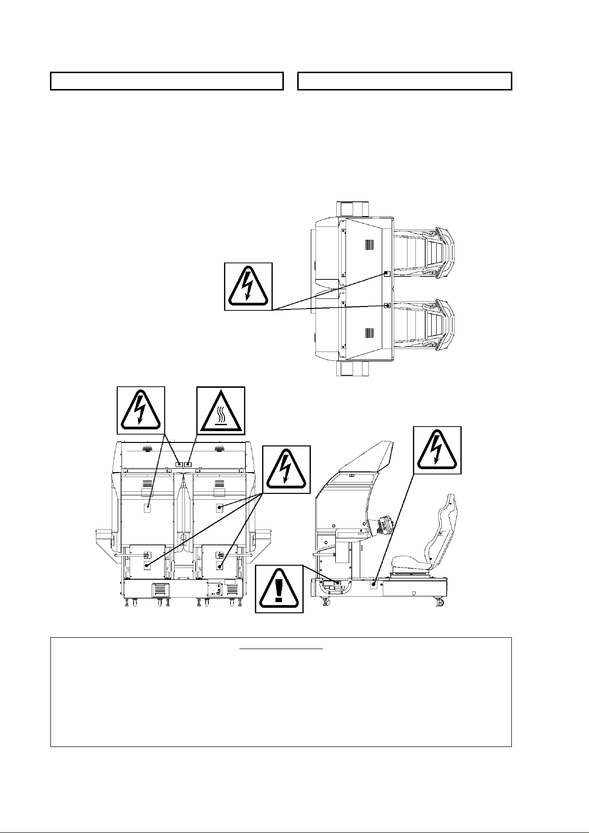
In order to prevent accidents warning stickers and printed instructions are applied in the places where a potentially
hazardous situation relating to the product could arise. Be sure to comply with these warnings.
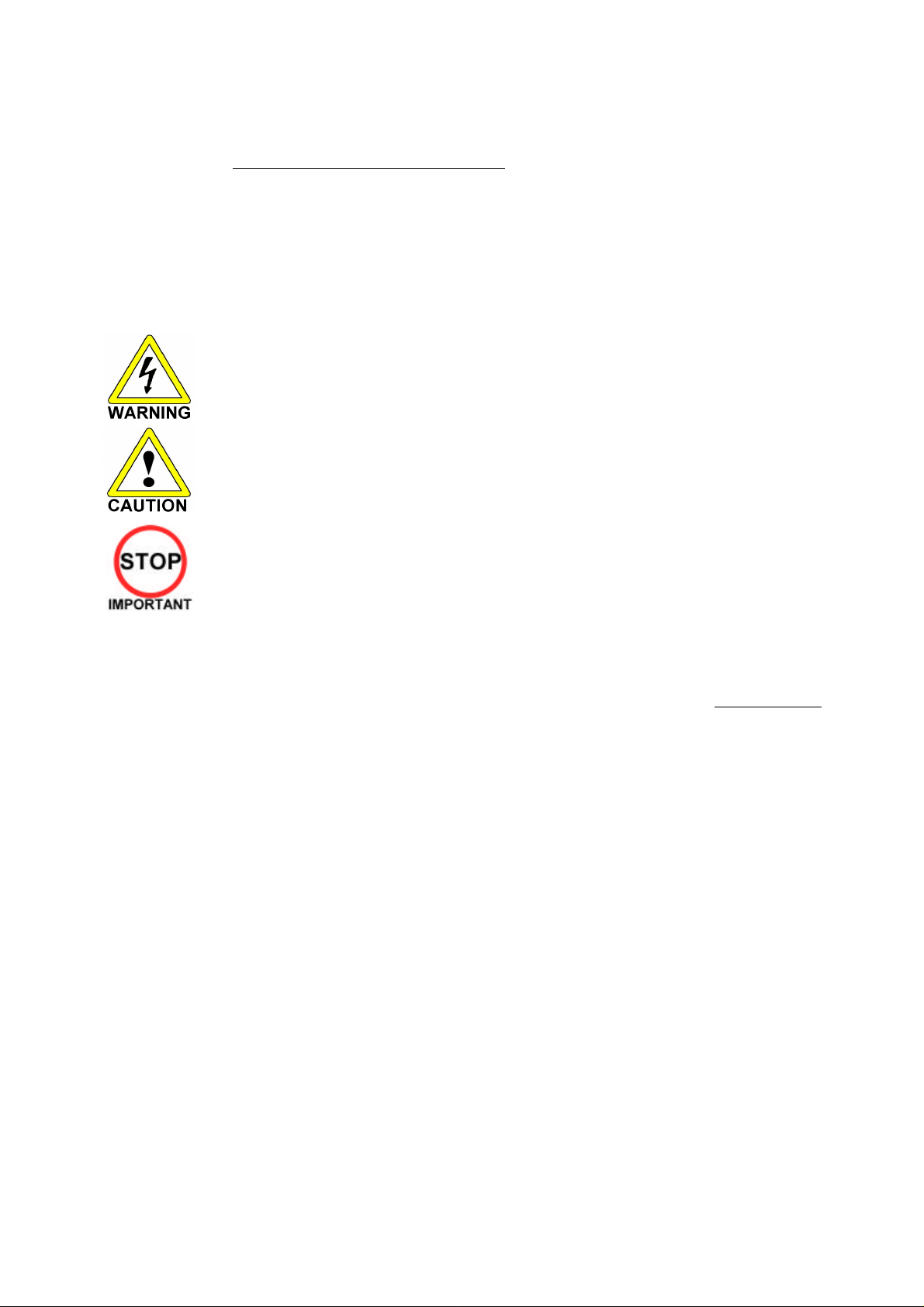
Indicates that mishandling the product by disregarding this warning will cause a potentially
hazardous situation that can result in death or serious injury.
Indicates that mishandling the product by disregarding this caution will cause a potentially
hazardous situation that can result in personal injury and or material damage.
This is cautionary information that should be complied with when handling the product.
Indicates that mishandling the product by disregarding this will cause a potentially
hazardous situation that may not result in personal injury but could damage the product.
Be sure to turn off the power and disconnect from the mains supply before working on the machine.
Ensure that the correct fuses are fitted to the machine. Details of these are enclosed in the Service Manual.
Ensure that only qualified Service Engineers perform any maintenance work on the machine.
Specification changes, removal of equipment, conversion and/or additions not designated by SEGA are not permitted
and will invalidate this product’s CE conformity.
Warning labels or safety covers for personal protection etc, are component parts of the product. A potential hazard
will be created if the machine is operated while any parts have been removed. Do not operate the product if any
doors, lids or protective covers become damaged or lost. SEGA is not liable in any whatsoever for any injury and/or
damage caused by specification changes not designated by SEGA.
Before installing the product, check for the Electrical Specification Sticker, SEGA products have a sticker on which the
electrical specifications are detailed. Ensure that the product is compatible with the power supply voltage and
frequency requirements of the location in which the machine is to be installed.
Install and operate the machine only in places where appropriate lighting is available, allowing warning stickers to be
clearly read.
To ensure maximum safety for customers and operators, stickers and printed instructions describing potentially
hazardous situations are applied to potentially hazardous locations. Ensure that the product’s operating location has
sufficient lighting to allow any warnings to be read. If any sticker or printed warning is removed or defaced, do not
operate the machine until an identical item has replaced it.
Exercise great care when handling the monitor (applies only to product with monitor). Some of the monitor (TV) parts
are subject to high-tension voltage. Even after turning the power off some components are liable to high-tension
voltage. Only qualified service engineers should perform monitor repair and replacement.
In cases where commercially available monitors and printers are used, only the items relating to this product are
contained in this manual. Some commercially available equipment will have functions and reactions not referred to in
this manual. This manual should be read in conjunction with the specific manufacturer’s manual for such equipment.
Descriptions contained herein may be subject to change without prior notification.
The contents described herein are fully prepared with due care. However, should any question arise or errors be found
please contact SEGA AMUSEMENTS EUROPE LTD.
Descriptions contained herein may be subject to change without prior notification.
The contents described herein are fully prepared with due care. However, should any question arise or
errors be found please contact SEGA.
5

1.1. Inspections Immediately After Transporting The Product To The
Location
• Only QUALIFIED SERVICE PERSONNEL should carry out inspection.
Normally, at the time of shipment, SEGA products are in a state to allowing usage immediately after
transporting to the location. Nevertheless, an irregular situation may arise during transportation preventing
this. Before turning on the power, check the following points to ensure that the product has been
transported safely.
• Are then any dented parts or defects (cuts, etc.) on the external surfaces of the product?
• Are castors and leg adjusters present and undamaged?
• Do the power supply voltage and frequency requirements meet with the local supply?
• Are all wiring connectors correctly and securely connected? Unless connected in the correct direction,
connector connections cannot be made successfully. Do not insert connectors forcibly.
• Are all IC’s of each IC BD firmly inserted?
• Does the power cord have any cuts or dents?
• Do fuses meet the specified rating?
• Are such units such as monitors, control equipment, IC BD, etc. firmly secured?
• Are all earth wires connected?
• Are all accessories available?
• Can all doors and lids be opened with the accessory keys and/or tools?
6
CONCERNING THE STICKER DISPLAY CONCERNING WARNING STICKERS
SEGA product has stickers describing the product
manufacture number (Serial Number) and
electrical specification. If you require service
assistance you will require the Serial Number.
Identical machines may have different parts fitted
internally. Only by quoting the Serial Number will
the correct parts be identified.
SEGA product has warning displays on
stickers, labels or printed instructions
adhered/attached to or incorporated in the
places where hazardous situations can arise.
The warning displays are intended for the
accident prevention of customers and service
personnel.
SPECIFICATIONS
Installation Space (cm): 202 x 170
Height (cm): 187
Weight (kg): 492
Power consumption (max): Rated Voltage (V.AC): TBA (See Rating Plate on Base Box)
Rated Current (A): TBA (See Rating Plate on Base Box)
Note: Descriptions in this manual are subject to change without prior notice.
7

2. INTRODUCTION TO THIS SERVICE MANUAL
SEGA ENTERPRISES LTD. supported by its experience in electronic high technology of VLSI’s,
microprocessors etc. and with a wealth of experience, has for more than 30 years been supplying various
innovative and popular games to the world market. This Service Manual is intended to provide detailed
descriptions together with all the necessary information covering the general operation of electronic
assemblies, electro-mechanicals, servicing controls, spare parts, etc. as regards this new SEGA product.
This manual is intended for those who have knowledge of electricity and technical expertise especially in
IC’s, CRT’s, microprocessors etc. Carefully read this manual to acquire sufficient knowledge before
working on the machine. Should there be any malfunction, non-technical personnel should under no
circumstances touch the internal systems. Should such a situation arise contact our head office.
SEGA AMUSEMENTS EUROPE LTD./ SEGA SERVICE CENTRE
Suite 3a
Oaks House
12 - 22 West Street
Epsom
Surrey
United Kingdom
KT18 7RG
8
3. INSTALLATION AND SERVICE INSTRUCTIONS
• Only QUALIFIED SERVICE PERSONNEL should carry out installation and
commissioning.
3.1. Handling And Installation Precautions
When installing or inspecting the machine, be very careful of the following points and pay attention to
ensure that the player can enjoy the game safely.
The game must NOT be installed under the following conditions:
• Outside, the game is designed for indoor use only.
• In areas directly exposed to sunlight, high humidity, dust, excessive heat, or extreme cold.
• In locations that would present an obstacle in the case of an emergency i.e. near fire equipment or
emergency exits.
• On unstable surfaces or surfaces subject to vibration.
• Where liquids, other than routine cleaning, may come into contact with the game.
Important:
• Only Qualified Service Personnel should install this machine.
• Be sure to switch the supply power OFF and remove the mains supply plug from the machine before
any work is carried out on the machine.
• Do not attempt to repair the PCB’s (Printed Circuit Boards) yourself. This will void the warranty. The
PCB’s contain static sensitive devices that could be damaged.
• Always return a faulty part to your distributor with adequate packaging and protection.
• When removing the plug from the mains always grasp the plug not the cable.
• Do not use a fuse that does not meet the specified rating.
• Make sure all connections are secure before applying power.
9
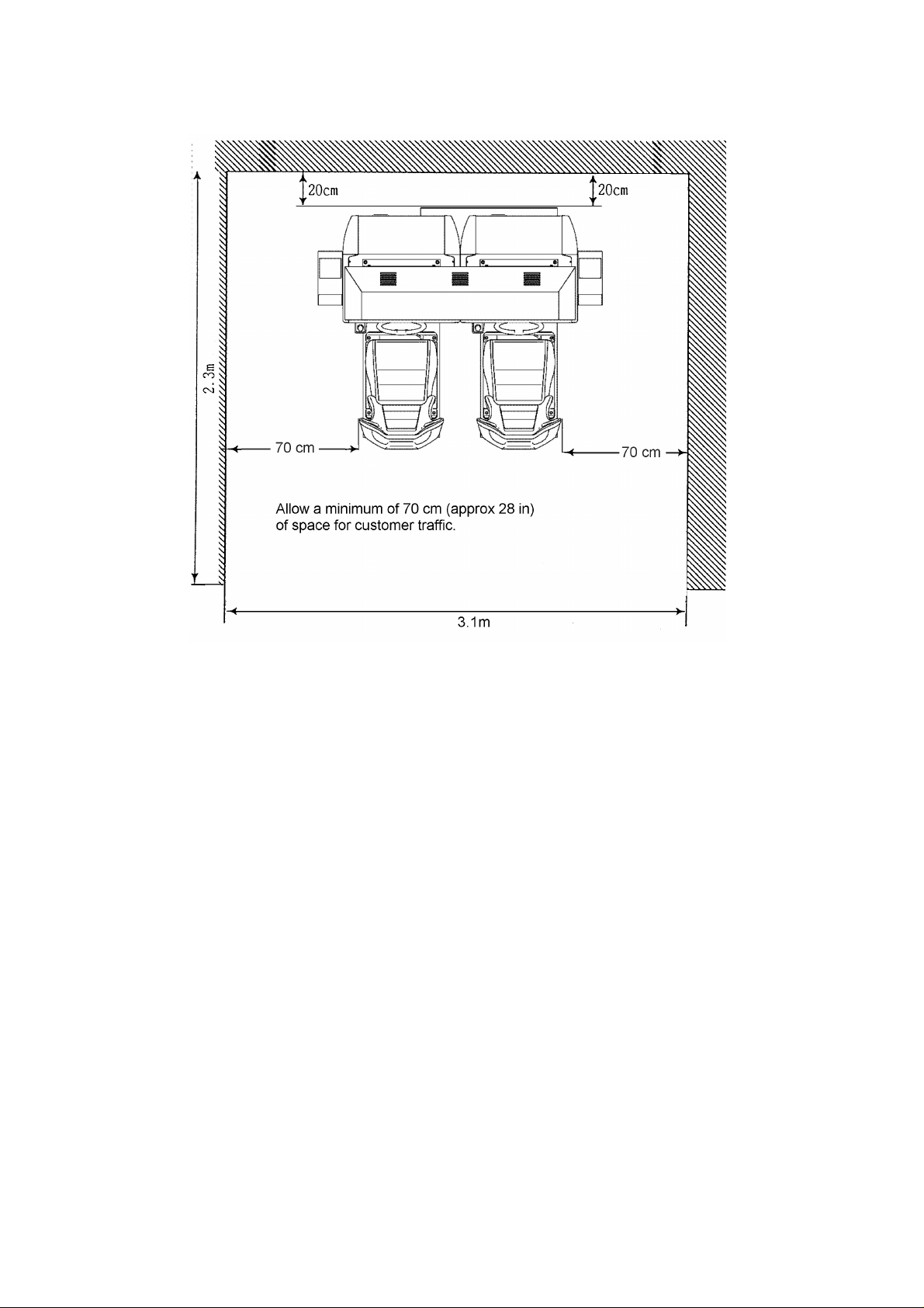
Installation Space
10

• Ensure that the mains lead is not damaged. If the mains lead is damaged in any
way there could be a danger of electric shock or a fire hazard.
• Ensure that the power supply is fitted with circuit protection. Using the power
supply without circuit protection is a fire hazard.
3.2. Coin Handling
Standard Sega machines are fitted with a SR3 coin mechanism, however, as a service to our customers
Sega machines can be supplied with no coin mechanism or door allowing the customer to fit a coin
handling option from the approved list. Fit only the coin handling arrangements detailed below and follow
the instructions provided in Section 3.7.6. Failure to fit the coin handling options detailed or failure to
follow the installation instructions will render the machine, under the CE marking directive, void.
Approved coin handling options:
• Coin controls SR3
• Generic mechanical
• Mars (MS111B1 and ME115)
• SECI RM4-G20
11
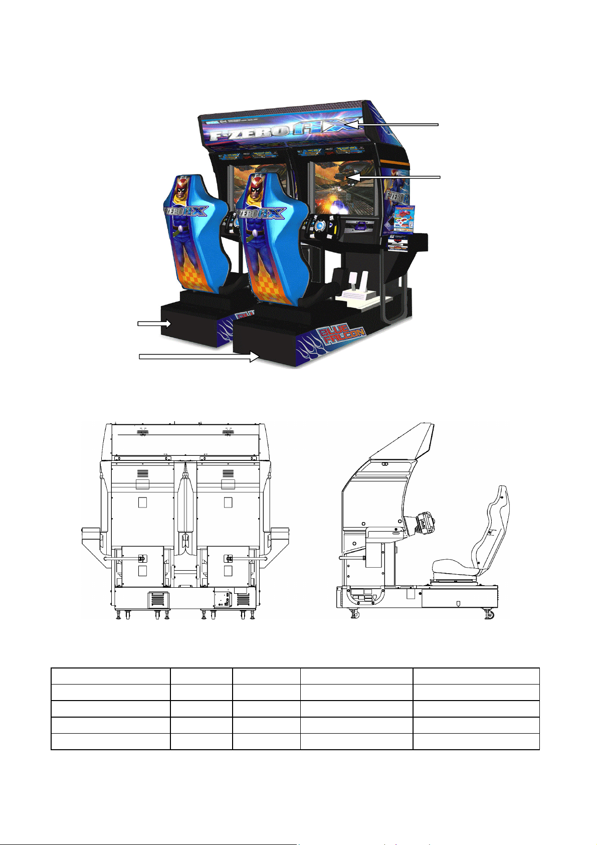
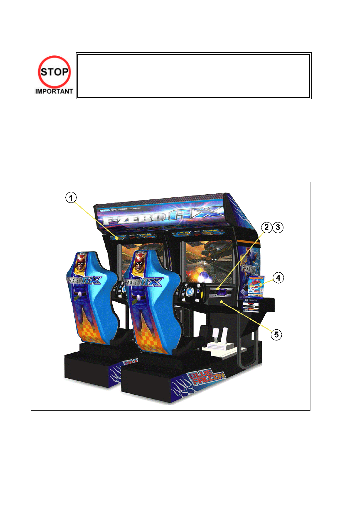
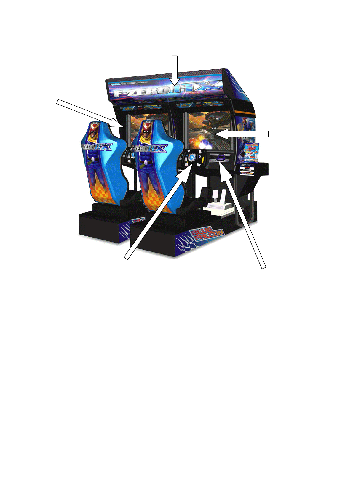
3.3. Name Of Parts
BILLBOARD
2P SIDE COCKPIT
1P SIDE COCKPIT
29 TYPE MONITOR
Width (cm) Length (cm) Height (cm) Weight (kg)
¯COCKPIT (EACH) 101 165 152 224
COIN CHUTE TOWER 27 33 57 15
BILLBOARD 160.9 61.7 35.4 36
When Assembled 202 170 186.4 492 Approx.
12
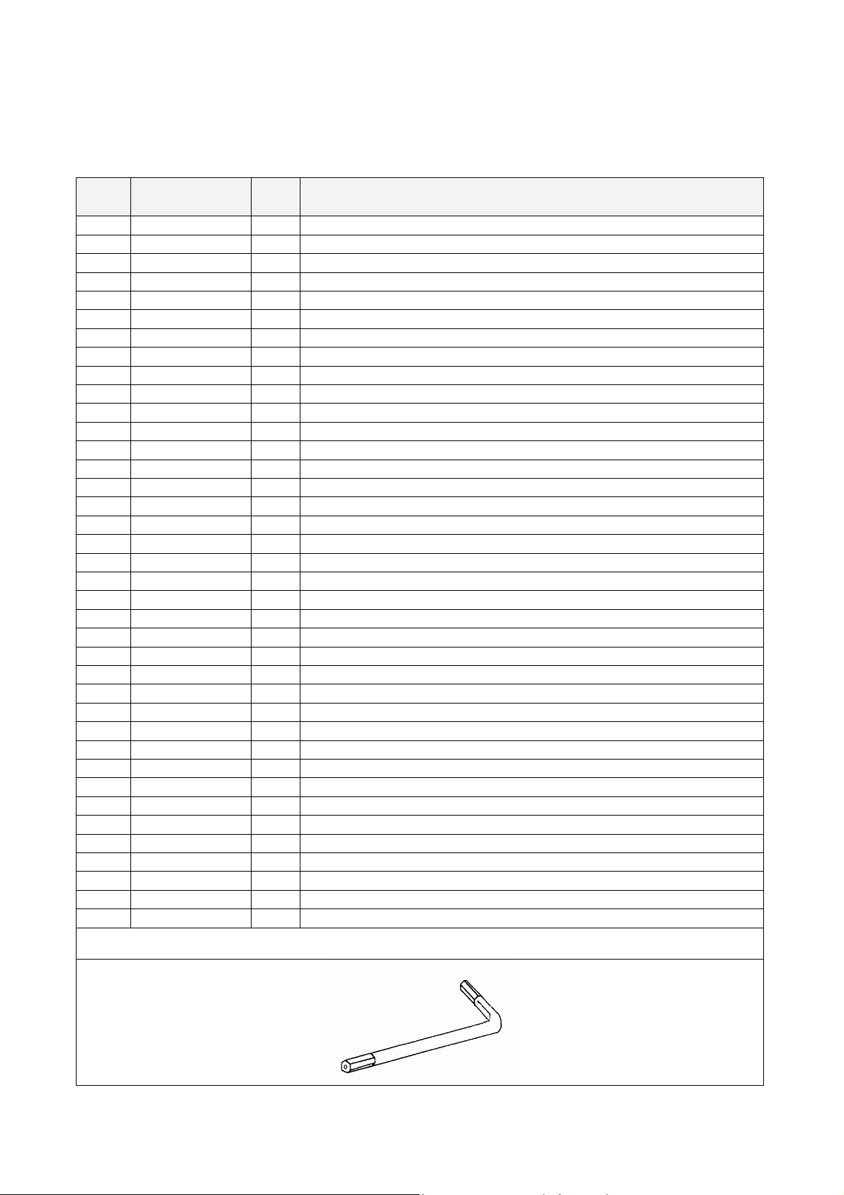
3.4. Accessories
The machine is supplied with an installation kit. Please ensure the following parts are supplied:
ITEM PART NO. QTY DESCRIPTION
1 FZR-0200UK 1 ASSY BILLBOARD
2 FRI-0300UK 1 ASSY COINCHUTE TOWER FRI
3 ORT-0500UK 1 ASSY WIRE COVER ORT TWIN
4 DYN-0013 1 JOINT PIPE
5 DYN-0006XUK 1 AC COVER B
6 SRT-0018UK 1 AC COVER C
7 DYN-0019UK 1 AC COVER D
8 RAL-XXXX-14UK 1 TIE BRACKET RALLY
9 SPG-0008 2 BILLBOARD HOLDER
10 422-0911UK 1 PLAY INSTR FZR TWIN MULTI
11 422-0912UK 2 SUB INSTR FZR TWIN MULTI
13 PK0347 1 INST KIT BOX FZR TWIN
15 FZR-0022-01 2 STICKER CARD SLOT FZR B ENG
16 601-11334-01 3 CARD PACKAGE FZR ENG
17 601-11050-91 2 CLEANING KIT
18 220-5753 1 VOL CONT B-5K OHM (TOCOS)
19 PK0343 0.5 PALLET INST KIT
20 FZR-0020UK 2 STICKER CARD SLOT FZR C MULTI
21 FZR-1297UK 2 STICKER MEMORY CAUTION MULTI
22 FZR-2024UK 2 STICKER MEMORY SLOT LWR MULTI
101 440-CS0186UK 2 STICKER C EPILEPSY MULTI
104 OS1241 6.5 TAPE RF20 XWEAVE 50mmX50M ROLL
201 030-000825-SB 20 M8X25 BLT W/S BLK
202 068-852216-0B 20 M8 WSHR 22OD FLT BLK
203 000-P00412-WB 15 M4X12 MSCR PAN W/FS BLK
204 050-F00400 3 M4 NUT FLG SER PAS
401 420-5827 1 SERVICE MANUAL SANWA 31K
402 420-6770-01UK 1 SERVICE MANUAL FZR TWIN
403 OS1019 2 SELF SEAL BAG 9X12.3/4
404 540-0006-01 1 WRENCH M4 TMP PRF
405 540-0007-01 1 WRENCH M5 TMP PRF
406 540-0009-01 1 WRENCH M8 TMP PRF
407 220-5484 1 VOL CONT B-5K OHM
408 SAECE-xxx 1 DECLARATION OF CONFORMITY
409 514-5078-5000 2 FUSE 5X20 CERAMIC SB 5000mA
411 420-6620UK 1 SERVICE MANUAL GD ROM SYSTEM
416 509-6036 1 SW MICRO MATSUSHITA AM51615A7
418 220-5775 1 VOL CONT B-10K OHM W/BD
Item 404-406 - Tamper-proof TORX wrench.
13

3.5. Shipping The Game Board and GD-ROM Drive
Observe the following precautions when sending the TRIFORCE or GD-ROM drive out for servicing or
repairs.
The carton boxes (included) are needed to ship these parts, and should therefore be stored in a safe place
to ensure that they are not lost.
• When sending parts in for repairs, they should be configured as follows:
(1) TRIFORCE:
- Leave the key chip installed in the board.
(2) GD-ROM drive:
- Remove the drive bracket.
- Eject the GD-ROM disc, place it in its case, and store in a safe place.
• Remove the wire harnesses and cables from the TRIFORCE and GD-ROM drive before sending
them in for repairs.
• Do not disassemble the TRIFORCE or GD-ROM drive. Place them in the carton box as is when
sending them in for repairs.
• Provide a clear, detailed description of the game used and the observed problems when sending
to the indicated repair center.
3.5.1. How To Use The Triforce Carton Box
Fold the packaging in the order specified in the diagram and wrap it around the TRIFORCE, making sure
that board and box are aligned correctly. Finally, place it in the carton box.
Failure to wrap the product as specified in the diagram may cause damage to parts.
14
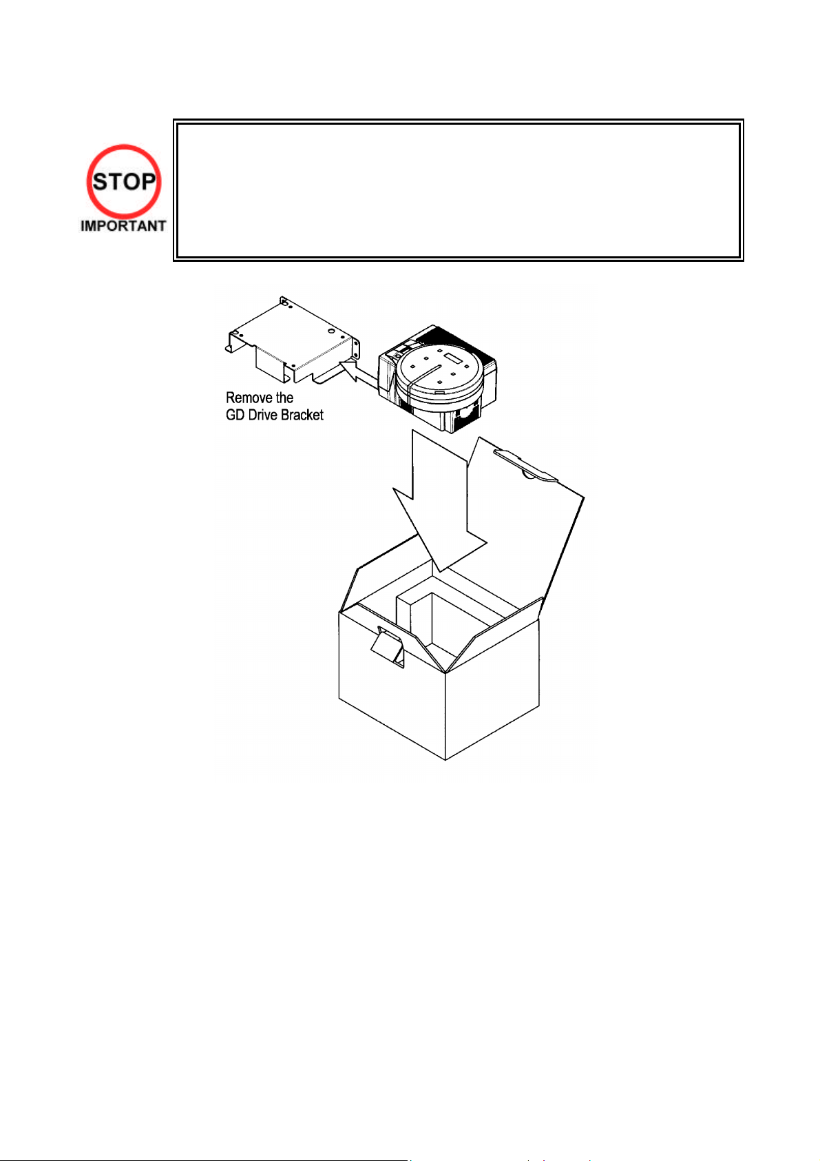
3.6. Shipping The GD-ROM Drive
• When returning the GD-ROM DRIVE for repair or replacement, be sure to package it
in the original card transit box - THERE ARE NO USER-SERVICEABLE PARTS
INSIDE.
• Ensure the GD-ROM Disk is removed and the GD-ROM Drive Lid is replaced on the
unit, with fixing screw, before packaging. Also, remove the GD-ROM Drive Bracket
and store with the four screws for reuse.
• Failure to return the GD-ROM DRIVE in this manner may invalidate the warranty.
15
3.7. Assembly Instructions
• Perform the assembly by following the procedure herein stated. Failure to
comply with the instructions, for example, inserting the plug into an outlet at a
stage not mentioned in this manual can cause an electric shock
• Assembling should be performed as per this manual. Since this is a complex
machine, erroneous assembling can cause damage to the machine, or
malfunction to occur.
• Do not attempt to complete this work alone, a minimum of 2 people are required.
• Only QUALIFIED SERVICE PERSONNEL should carry out assembly.
When carrying out the assembly work, follow the procedure in the following 7 item sequence
STEP 1 ASSEMBLING THE COCKPIT
STEP 2 SECURING IN PLACE (LEG ADJUSTER ADJUSTMENT)
STEP 3 BILLBOARD INSTALLATION
STEP 4 INSTALLING THE AC COVERS (WIRE COVERS)
STEP 5 COIN HANDLING INSTALLATION
STEP 6 CONNECTION TO POWER SUPPLY
STEP 7 ASSEMBLY CHECK
Note that the parts contained within the installation kit are required for the assembly work.
• Fit all fixings loosely first as detailed in step 1, then position all components
before finally tightening fixings at step 6.
16
3.7.1. Applying The Play Instructions
• Only QUALIFIED SERVICE PERSONNEL should carry out this operation.
Supplied in the installation kit are 5 sets of play instructions in 5 languages. Select the language of
your choice and apply in the following areas:
1. 422-0912UK: Instructions (on monitor mask)
2. FZR-1297UK (on top control panel over memory slot)
3. 422-0911UK: Instructions (on top of control panel)
4. FZR-0020UK Card Instructions (on card R/W lid)
5. FZR-2024UK (under memory slot)
17
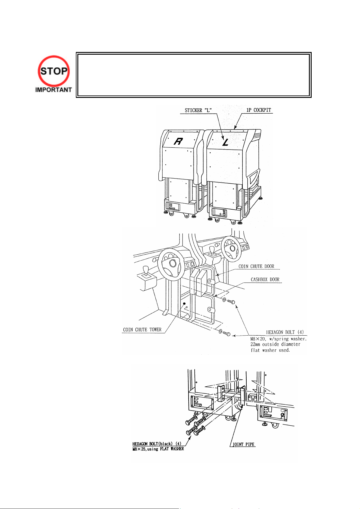
3.7.2. Assembling The Cockpit
• Only QUALIFIED SERVICE PERSONNEL should carry out this operation.
1. Place the two cockpits
side by side. Position the
1P cabinet, which has the
IEC inlet at the left hand
side when viewed facing
the monitor. STICKER L
is attached to the back of
the 1P cabinet and
STICKER R on the back
of the 2P cabinet
2. Install the coin chute
tower in between both
cabinets. Open the coin
chute door and the cash
door and secure with the
4 hexagon bolts from
inside the doors. At this
time, make sure the bolts
are only loosely fitted.
Note: Door may open in opposite way to that shown above
3. Install the joint pipe on
the rear-side of both
cabinets by securing with
4 hexagon bolts, at this
time loosely.
18
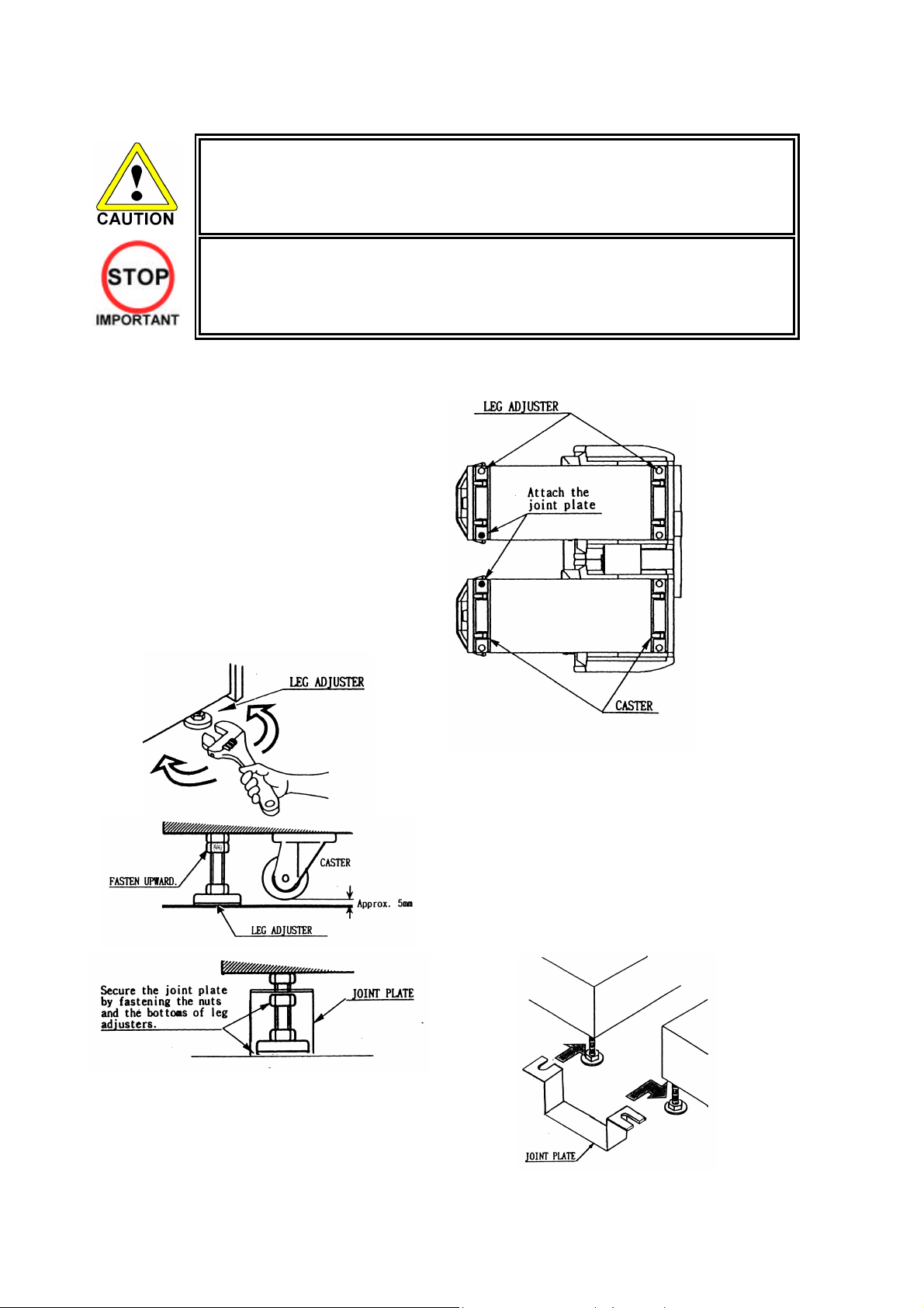
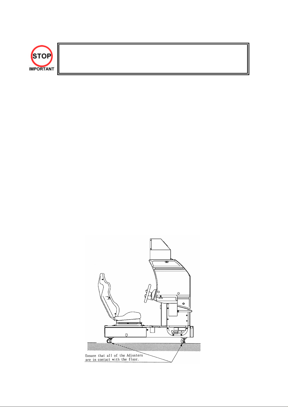
3.7.3. Securing In Place (Leg Adjuster Adjustment)
• Make sure all of the leg adjusters are in contact with the floor. If they are not the
machines may move and cause injury. This operation requires 2 people.
• Only QUALIFIED SERVICE PERSONNEL should carry out this operation.
This machine has eight castors and eight leg adjusters. When the installation position is decided, unscrew
the leg adjusters so that they raise each caster a minimum of 5mm from the floor. Make sure the machine
is level.
1. Move the machine to the installation position.
When installing against or close to a wall, be
sure to allow an adequate space to allow the
player access to the machine.
2. Make the leg adjusters contact the floor.
Adjust using a spanner as shown below so
that a minimum of 5mm exists between the
casters and the floor. Make additional
adjustment so that the machine is level.
3. Slide the joint plate onto the shafts of the
indicated leg adjusters. Tighten the lock nut
on all eight leg adjusters. This will secure the
joint plate.
After securing the leg adjuster bolts, fully tighten all bolts temporarily attached in STEP 1 above.
19
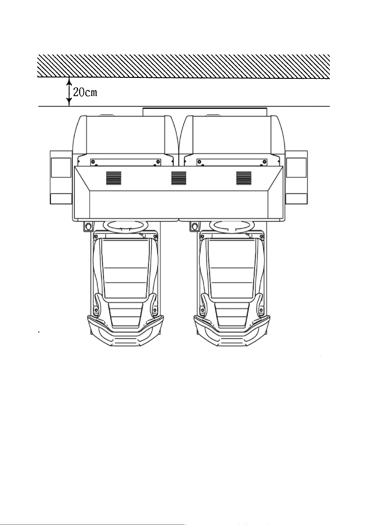
Ensure adequate ventilation is maintained as detailed below
20
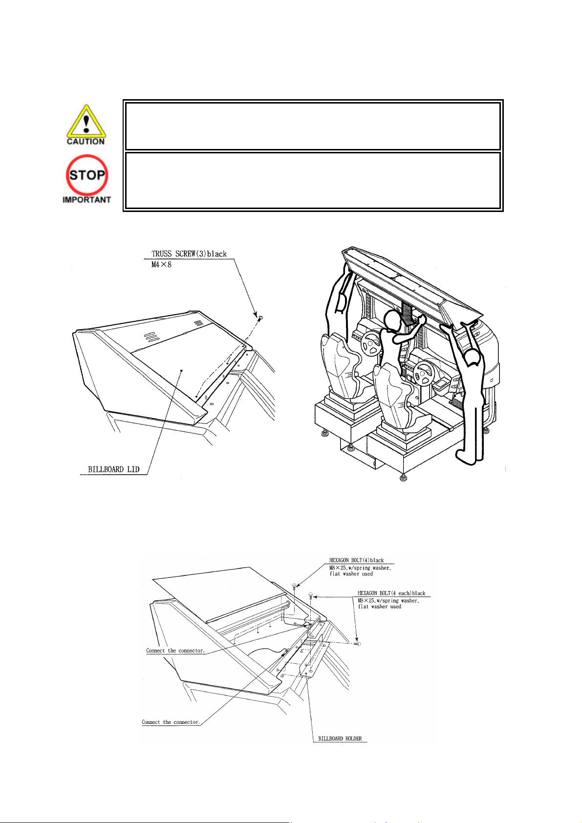
3.7.4. Billboard Installation
• One person alone cannot perform the installation of the billboard assembly. Seek
assistance before attempting this operation
• Only QUALIFIED SERVICE PERSONNEL should carry out this operation.
1. Install the billboard base over the two cockpits.
2. Mount the billboard by fitting it onto the billboard base.
3. Install the billboard holders using 2 hexagon bolts each to secure them to the cabinets.
4. Connect the wire connectors from the billboard box to the connectors on the cabinets and install
the connector covers using two screws for each.
21
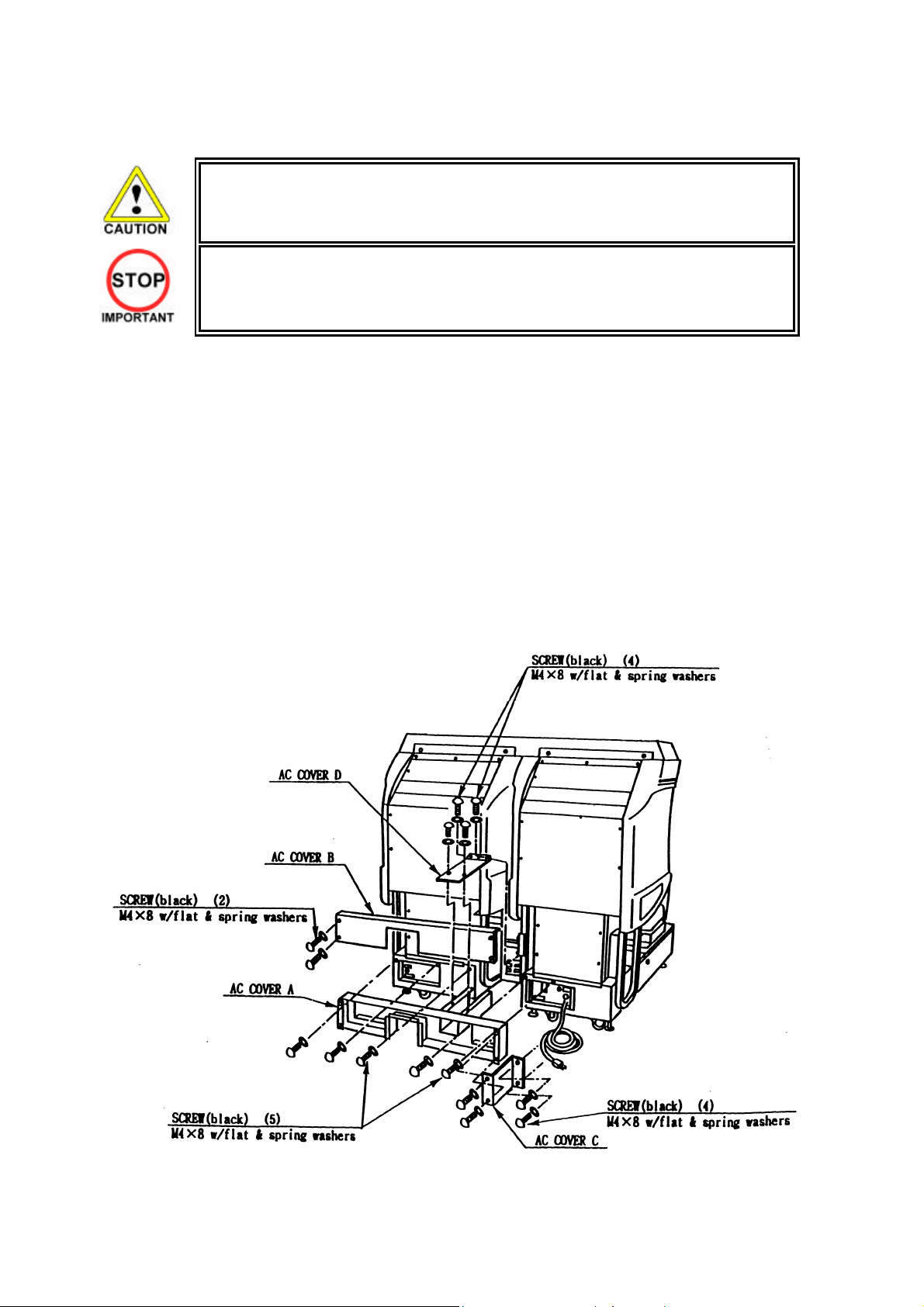
3.7.5. Installing The AC Covers (Wire Covers )
• Be sure that the machine is not connected to the mains supply before attempting
this operation.
• Only QUALIFIED SERVICE PERSONNEL should carry out this operation.
The AC Wire Covers are used for protecting the interconnecting wiring and the fibre optic cables. When
carrying out this operation be very careful so as not to trap any wire between the covers. Pay attention
when handling the fibre optic cables as excessive bending may cause damage.
1. Attach AC Cover A to the rear of the cabinet using 5 screws.
2. Make all the wiring connections between the two cockpits and the Coin Chute Tower. The wiring
connectors are colour coded and cannot be fitted into the wrong size connectors. Do not force any
connectors together.
3. Connect the earth wires between the two AC Brkts, the AC Covers and the Coin Chute Tower.
4. Insert the fibre optic cables into the fibre optic connectors. Ensure that the “RX” connection on the
1P cockpit is connected to the “TX” connector on the 2P cockpit. The other fibre optic connects
the “TX” connector of the 1P cockpit to the “RX” connector of the 2P cockpit.
5. Insert AC Cover B into AC Cover A from above and secure using 2 screws. Be sure not to trap
any cables.
6. Secure AC Cover C and AC Cover D using 4 screws each.
22
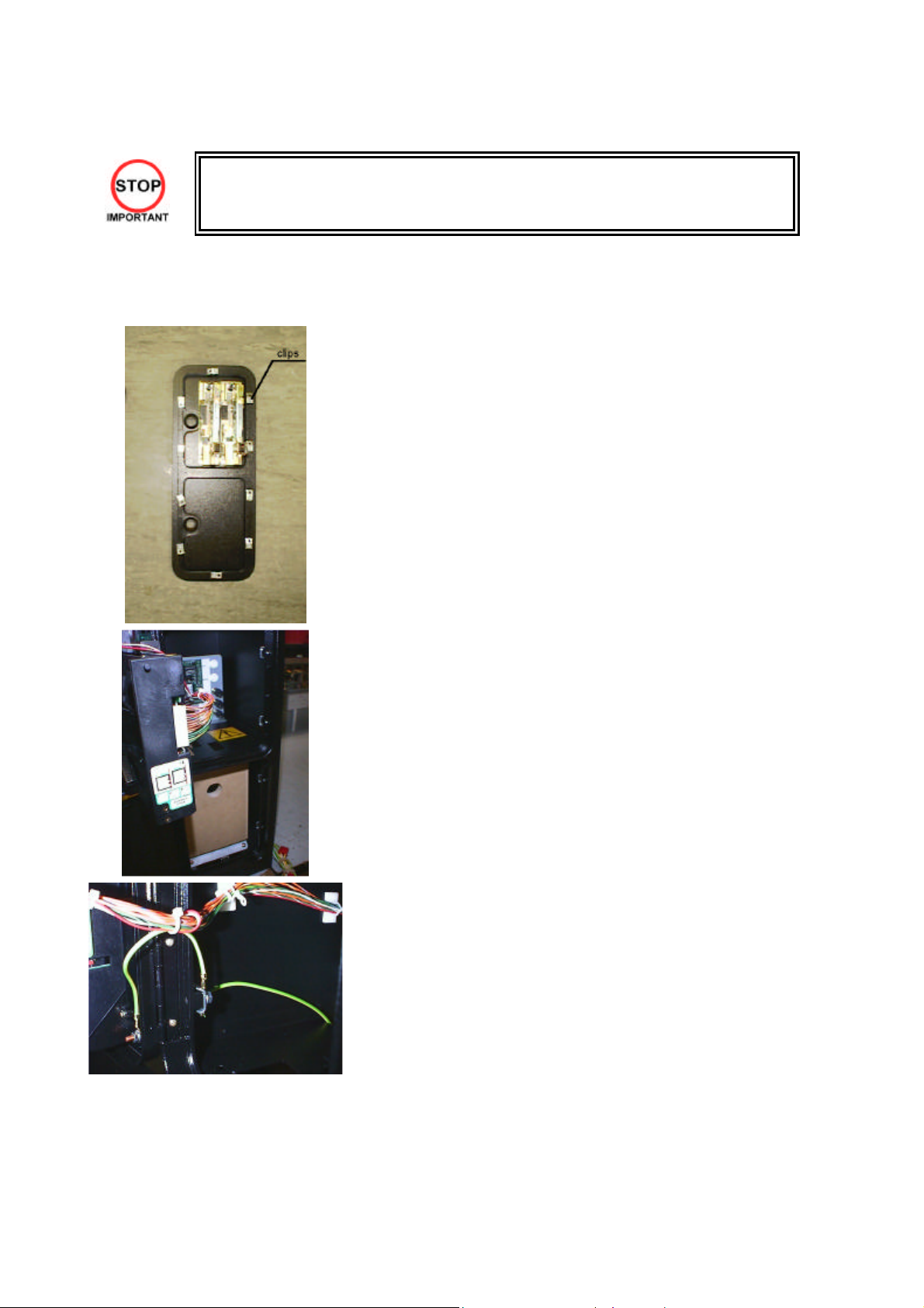
3.7.6. Coin Handling Installation
• Only QUALIFIED SERVICE PERSONNEL should carry out this operation.
When fitting the coin mechanism to the door please refer to the specific manufacturers installation
instructions for that coin mechanism. To fit the door to the machine, follow the procedure below.
• Loosen all of the bolts on the frame, which secure the clips.
• Turn all clips in towards the door.
• Position the door into the aperture in the machine.
• Turn the clips around so that they will hold the door in the
machine.
• Tighten all of the bolts.
• Ensure that the door is earthed to the frame and the frame is
earthed to either the VTS bracket or the coin chute tower.
23
3.7.6.1.Wiring Connections.
COIN MECH LOOM INSTALLATION
C220B LM1006IDC
LM1006LAMP-0.1
GENERIC
MECHANICALS
MARS
MS111B1
MARS ME115
SECI, C120,
SR3
LM1008
LM1008-LAMP
LM1007
LM1008-LAMP
OWN LOOM AND
LM1006LAMP-0.1
• Attach the lamp holder to the bracket on the coin return
button.
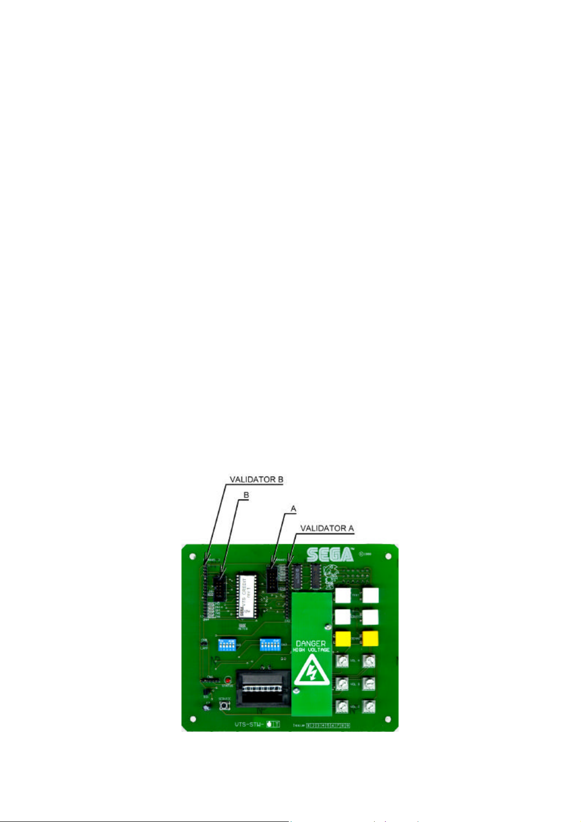
• Attach one 15-way connector to the C220 coin mech.
• Attach the other 15-way connector to Validator A on the
credit board.
• Attach the 2-way connector to ‘LAMP’ on the VTS
board.
• Fit the two lamp holders behind the coin return buttons.
• Attach the blue cable and orange cable to one mech’s
microswitch switch.
• Attach the blue/green cable and orange/green cable to
the other mech’s microswitch.
• Attach the 2-way mate and lok plug to the 2-way mate
and lok cap provided.
• Attach one 15-way connector to Validator A and the
other to Validator B on the credit board
• Fit the lamp holder to the bracket behind the coin return
button.
• Fit one of the 13-way connectors to the coin mech.
• Fit the other 13-way connector to Validator A on the
credit board. Note the 13-way connector is keyed and
this key must coincide with the key on the credit board.
• Attach the lamp holder to the bracket on the coin return
button.
• Attach the 2- connector to ‘LAMP’ on the VTS board.
• Attach the validator’s own loom to position A on the
credit board
VTS credit board assembly
24
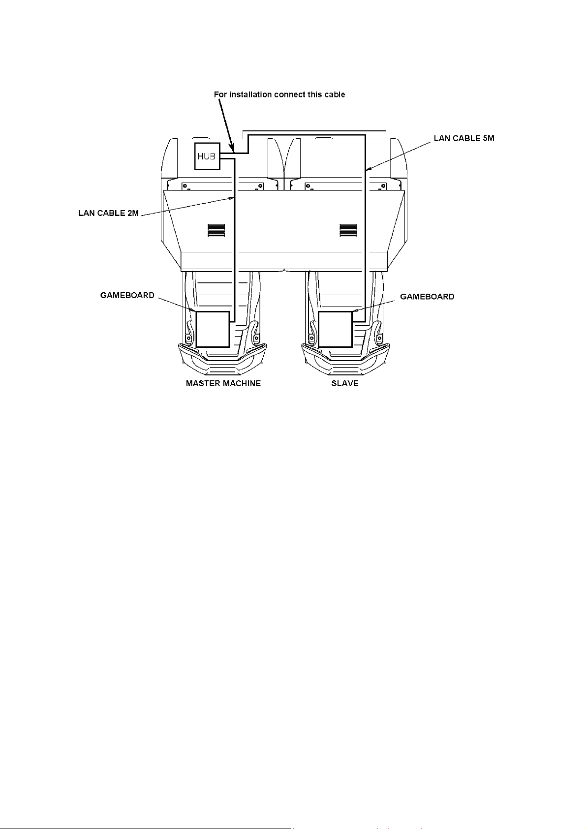
3.7.7. Communication Cables
The master (left) machine’s LAN cable will come pre-connected to hub.
Connect the slave machine’s LAN cable (bundled up at the back in a loop) across via the AC cover to the
hub of the master machine and connect to one of the hub’s ports.
For machine set-up refer to Section 5.2.10.5.
25
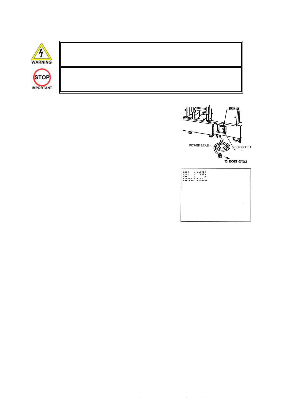
3.7.8. Connection To The Power Supply
• This operation may only be carried out once the machine has been completely
assembled.
• Only QUALIFIED SERVICE PERSONNEL should carry out this operation.
The AC Unit is located on the rear of the 1P cockpit. Using the power
lead supplied connect this to the mains socket at the wall.
1. Turn the mains switch on.
2. Turn the switch on the AC bracket on.
3. Once power is turned on, the fluorescent lamp lights up. The
Start System Screen displays after a lapse of several
seconds. This is followed by the screen that indicates that the
network is currently being checked if the communication
mode has been set. If there is a bad or improper
communication connection, each screen will not proceed to
the next, remaining on the currently Network Check Screen.
If this occurs, resolve the error according to the instructions
in this document.
4. If the communication mode has not been set or the
communication check ends normally, the Motor Check
Screen returns. While the Motor Check Screen is on-screen,
the steering wheel can move either clockwise or counter
clockwise. If you touch the wheel, the motor check is
hindered and the game will not operate normally. So, you
must not touch it at this time. Failures are displayed, if found.
Resolve the errors according to the instructions in this
document.
5. Once all the above steps have been completed, the
Advertise Screen displays and voices are output through the
left and right loudspeakers, unless you have set the machine
so that no voices are output during the Advertise mode.
6. This product retains the number of credits and the ranking
data even after the power is turned off. It does not retain data
about the fractional number of coins (i.e., the number of
coins not reaching one credit) or the bonus adder count.
26
ering wheels turn in both
Sound is
emitted
Fluorescent lamps are always lit
On screen
images are
output
Ste
directions
Control Panel
27
3.7.9. Assembly Check
In the Test Mode, ascertain that the assembly has been made correctly and IC BD is satisfactory (see
Section 5.2.1).
In the test mode perform the following test:
3.7.9.1.Memory Test
Selecting RAM TEST or MEDIA BOARD TEST
from the menu screen in System Test mode will
cause the machine to automatically perform a test
of memory on the game boards. If GOOD is
displayed next to the number of each memory
segment, the game boards are working properly.
Select SYSTEM INFORMATION to display
information on the main game board and the media
board. If the information is displayed correctly, this
indicates that the game boards are functioning
properly.
MEDIA BOARD TEST 1/2
DIMM BOARD(TYPE 3)
VERSION ****
STATUS GOOD
CHECKING 100%
DIMM TEST
DIMM0 - GOOD
DIMM1 - NONE
GD-ROM - GOOD
PRESS TEST BUTTON TO EXIT
AUX MEMORY GOOD
TEST BUTTON TO EXIT
MEDIA BOARD TEST 2/2
NETWORK BOARD
CHECKING 100%
NETWORK BOARD TEST
RAM CHECK _ GOOD
-- COMPLETED --
PRESS TEST BUTTON TO EXIT
RAM TEST
VERSION ****
STATUS GOOD
SYSTEM INFORMATION
MAIN BOARD
REGION ****
BOOT VERSION ****
FIRM VERSION ****
FPGA VERSION ****
SERIAL NO. ***************
MEDIA BOARD
DIMM BOARD(TYPE 3) + GDROM
MEMORY SIZE 512MB
FIRM VERSION ****
SERIAL NO. ***************
NETWORK BOARD
FIRM VERSION *****
PRESS TEST BUTTON TO EXIT
28
3.7.9.2.Input Test
Select INPUT TEST from the menu screen in either System Test mode
JVS TEST
INPUT TEST
NODE 1/1
SYSTEM 00
PLAYER 1 1 0000
PLAYER 2 2 0000
COIN 1 1 0000
COIN 2 2 0000
ANALOG 1 0000
ANALOG 2 0000
ANALOG 3 0000
ANALOG 4 0000
ANALOG 5 0000
ANALOG 6 0000
ANALOG 7 0000
ANALOG 8 0000
STEERING X 0(~FF) SERVICE OFF(ON)
STEERING Y 0(~FF) TEST OFF(ON)
PADDLE LEFT OFF(ON)
PADDLE RIGHT OFF(ON)
BOOST OFF(ON)
GAS 0(~FF)
BRAKE 0(~FF)
START BUTTON
VIEW CHANGE 1 OFF(ON)
VIEW CHANGE 2 OFF(ON)
VIEW CHANGE 3 OFF(ON)
VIEW CHANGE 4 OFF(ON)
PRESS TEST AND SERVICE BUTTON TO EXIT
INPUT TEST
29
3.7.9.3.Sound Test
SOUND TEST
OUTPUT TYPE STEREO
RIGHT SPEAKER OFF
LEFT SPEAKER OFF
àEXIT
SELECT WITH SERVICE BUTTON
AND PRESS TEST BUTTON
3.7.9.4.CRT Test
• Only QUALIFIED SERVICE PERSONNEL should carry out this operation.
In the system test mode, selecting SOUND TEST
causes the screen (on which sound related BD and
wiring connections are tested) to be displayed.
Check if the sound is satisfactorily emitted from
each speaker and the sound volume is appropriate.
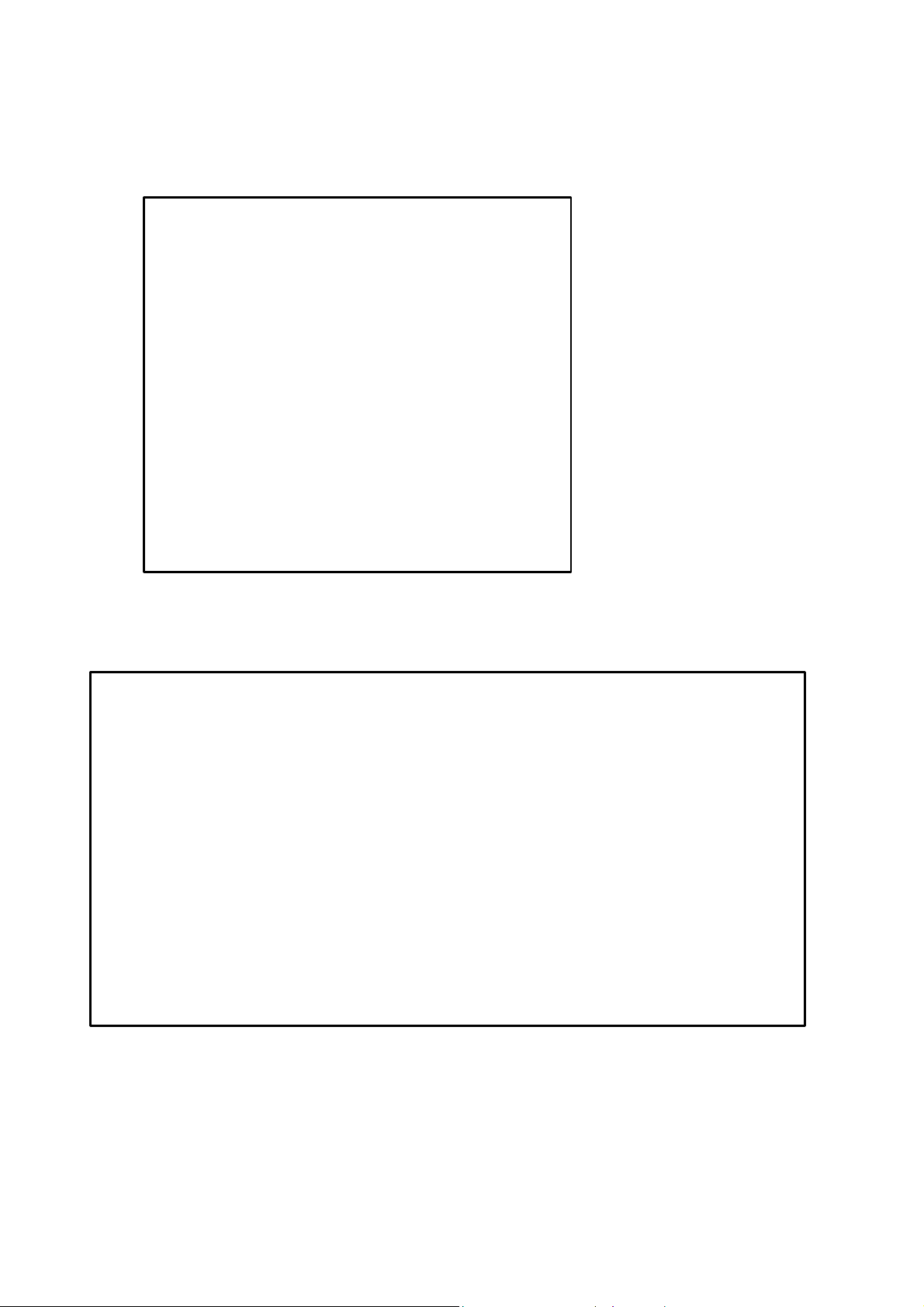
C.R.T. TEST 1/2
C.R.T TEST
PAGE 1/2
RED
In the TEST mode select CRT test to check the
screen is satisfactory.
Although the projector has been set up at the
factory before shipment, check to see if the screen
GREEN
BLUE
WHITE
PRESS TEST BUTTON TO CONTINUE
needs adjustment.
C.R.T. TEST 2/2
PRESS TEST BUTTON TO EXIT
30

3.7.9.5.Output Test
OUTPUT TEST
START BUTTON OFF(ON)
VIEW CHANGE 1 OFF(ON)
VIEW CHANGE 2 OFF(ON)
VIEW CHANGE 3 OFF(ON)
VIEW CHANGE 4 OFF(ON)
BOOST OFF(ON)
STEERING
CENTER OFF(ON)
LEFT OFF(ON)
RIGHT OFF(ON)
àEXIT
Select OUTPUT TEST from the menu screen in
Game Test mode to bring up a test screen for the
output devices (lamps, etc.).
If each output device activates correctly, the output
devices and their wiring connections are working
properly.
Perform the above inspections also at the time of monthly inspection
31

3.7.10. Moving The Machine
• When moving the machine, be sure to remove the plug from the power supply.
Moving the machine with the plug inserted can cause the power cord to be damaged,
resulting in a fire or electric shock.
• When moving the machine, retract the leg adjusters fully and ensure the casters make
contact with the floor. During movement pay careful attention so that the casters or leg
adjusters do not damage any other cabling laid on the floor. Such damage could result
in a fire or electric shock.
• Don’t push the cockpit cabinets from the side, as they may topple and cause damage.
• Don’t put excessive pressure on the glass or plastic components as damage or
personal injury may result if there is a breakage.
• Only QUALIFIED SERVICE PERSONNEL should carry out this operation.
Disassemble the cabinet into its components if
transporting up or down step level changes!
Do not push an individual cockpit from the side!
32

3.8. Fuses
• Never touch places other than those specified. Touching places other than those
specified can cause electric shock and short circuit. Disconnect the machine
There are a number of fuses used on this machine to protect the user and the machine from damage. Only
replace the fuse once you have remove the cause of its failure. Detailed below is a list of the fuses used,
their location and if relevant PCB reference:
PART NUMBER LOCATION TYPE & DETAILS QTY PER COCKPIT
514-5078-5000 IEC INLET (EP1302) 5x20 HRC SB 5000mA 1
514-5078-6300 838-11856CE-02 5x20 HRC SB 6300mA 1
514-5078-4000 400-5397-01 (F1) 5x20 HRC SB 4000mA 1
514-5078-6300 838-13578 (F1) 5x20 Ceramic SB 6300mA 1
514-5080-15000 838-14174(F1) 32x6.35 HRC SB 15000mA 1
514-5078-2500 838-14174(F2) 5x20 HRC SB 2500mA 1
514-5033-5000 400-5421-07512 (F11) 5x20 Glass T 125v 5 A 1
There are also fuses located on the Monitor PCB. Refer to the relevant Monitor manual supplied to
reference these fuses.
from the supply before attempting the replacement of any fuse.
• Only QUALIFIED SERVICE PERSONNEL should replace FUSES.
33

3.9. Maintenance
• Only Qualified Service Personnel must carry out maintenance.
• Ensure that the mains power is switch OFF and disconnected before attempting any
work.
• The CONTROL PANEL ASSEMBLY is heavy and may cause injury or damage to the
machine if dropped. Use an assistant when removing and replacing it.
• In order to prevent an electric shock and short circuit, be sure to turn power off before
performing work by touching the interior parts of the product.
• Be careful not to damage the wires. Damaged wires may cause electric shock or short
circuit or present a fire risk.
• Do not touch undesignated places. Touching places not designated can cause electric
shock or short circuit.
• This work should be performed by the site maintenance individual or other skilled
professional. Performing work by non-technical personnel can cause electric shock
hazard.
• Do not perform work other than those specified in this Manual in order to prevent
accidents during performing work and operation after performing work. Performing
work not specified in this Manual may require special training for this product. If
performing work other than those stated in this manual is required for repair, contact
the offices herein stated in this manual or where you purchased the product from and
ask for repair or inquire how to repair.
• Be very careful when soldering. Handling a soldering iron carelessly may result in a
fire or a burn.
• Be extremely careful when heating the heat-shrinkable tube. Failure to do so may
result in a fire or burns.
• Do not drop parts when removing them. Dropping parts may damage them or cause
sudden accidents.
• To prevent accidents, more than one person must perform these operations.
• Exercise extreme caution when handling the internal parts of the Control Panel. Watch
out for damage, warping and loss. The loss of just one piece may result in damage to
or lead to faulty operation of the entire unit.
• When securing the plastic-made parts, do not excessively fasten screws and nuts.
Failure to observe this may damage the parts and cause injury due to fragments
resulting from damage.
• Be sure to perform volume's move value setting in the Volume Setting in the Test
Mode after replacing or adjusting the Volume. (See Section 5.)
34

3.9.1. Removing The Control Panel
Poor handle response/lack of response when adjusting the Volume in Test Mode may be caused by faulty
Volume alignment and/or a damaged Volume.
Follow the instructions below to adjust the gear alignment and/or replace the Volume.
If the Volume Shaft is rotating within its normal area of mobility, there is little chance the Volume can be
damaged by rotating the handle as far as possible to the left/right. With the handle in the centre position,
i.e. straight, and the Volume Shaft in the same direction shown in the diagram, attach the Volume so that it
aligns properly with the gears. The recommended value of the VR is within the range 78H | 88H when the
steering unit is in the straight position. In order to adjust or replace the Volume, follow the instructions
below to remove the Control Panel.
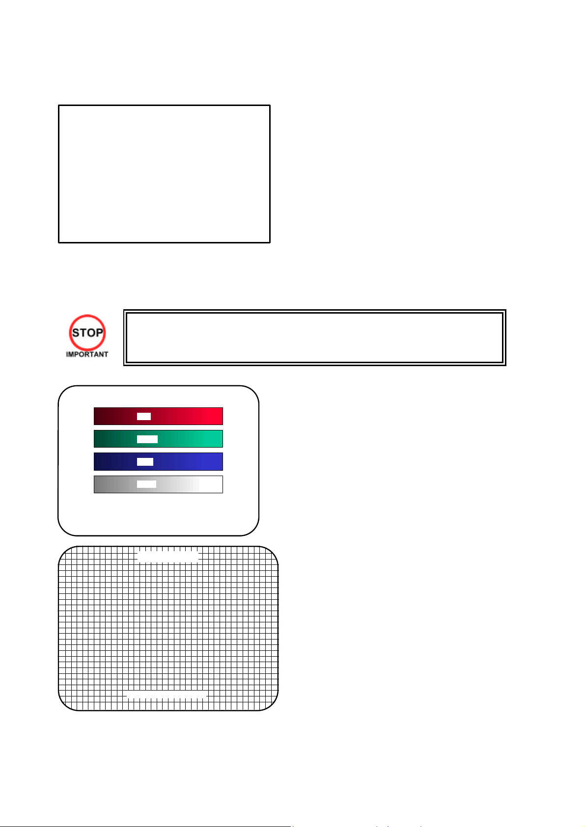
A 5 mm hexagonal wrench is required for the following procedure.
1. Turn off the power.
2. A Remove the 6 hexagon socket screws from the Control Panel.
3. The mass of the control panel is
approximately 23 kg. Removal and
installation of the control panel
should be performed by at least 2
people working together. The panel
should be firmly supported using
both hands.
35

D
ISCONNECT CONNECTOR
4. Unplug the 8 connectors and re move the
Control Panel. Be careful not to damage
any of the wiring.
3.9.1.1.Adjusting/Replacing The Volume
3.9.1.1.1.Adjustment Procedure
1. Loosen the 2 screws that secure the VR Bracket and move the VR Bracket to adjust the angle
and condition of the gear alignment.
2. Keeping the handle straight, align the gears so that the direction of the D Cut side of the Volume
Shaft matches that shown in the diagram.
3. Tighten the 2 screws and secure the VR Base.
4. Adjust the variable resistor settings on the Volume Setting screen (see 5.2.10.7).
5. Check to make sure the "STEERING X" value on the Input Test screen is within the range 80H+/8H when the steering unit is in the straight position.
36

3.9.1.1.2.Replacement Procedure
This procedure requires the following tools: Philips screwdriver for the M4 screws, 1.5 mm hexagonal
wrench, 11\12mm monkey wrench, nipper, cutter, wire stripper, soldering iron and industrial dryer.
1. Remove the connectors.
2. Remove the 2 screws securing the VR Bracket and remove the entire Bracket and Volume.
3. Loosen the 2 hexagon socket screws on the Gear and remove the Gear.
4. Remove the nut securing the VR Bracket, then separate the Volume from the VR Bracket and
replace it.
5. Adjust the variable resistor settings on the Volume Setting screen.
6. Check to make sure the "STEERING X" value on the Input Test screen is within the range 80H+/8H when the steering unit is in the straight position.
37

3.9.1.2.Greasing
• Be sure to use the designated type of grease. If a non-designated type grease is used,
components may break.
• Do not apply grease to any part of the machine other than those parts specifically
indicated. Doing so may result in malfunctioning and/or deterioration of parts.
• The period for greasing specified herein is a standard. Apply greasing to the specified
portions as occasion arises.
• Be sure to use a good quality, synthetic lubricant. Using a mineral-based lubricant will
cause damage to the plastic parts.
38

3.9.2. Steering Unit
• In order to prevent an electric shock and short circuit, be sure to turn power off before
performing work by touching the interior parts of the product.
• Be careful not to damage the wires. Damaged wires may cause electric shock or short
circuit or present a fire risk.
• Do not touch undesignated places. Touching places not designated can cause electric
shock or short circuit.
• This work should be performed by the site maintenance individual or other skilled
professional. Performing work by non-technical personnel can cause electric shock
hazard.
• Do not perform work other than those specified in this Manual in order to prevent
accidents during performing work and operation after performing work. Performing
work not specified in this Manual may require special training for this product. If
performing work other than those stated in this manual is required for repair, contact
the offices herein stated in this manual or where you purchased the product from and
ask for repair or inquire how to repair.
• Be very careful when soldering. Handling a soldering iron carelessly may result in a
fire or a burn.
• Be extremely careful when heating the heat-shrinkable tube. Failure to do so may
result in a fire or burns.
• Exercise extreme caution when handling the internal parts of the Steering Unit. Watch
out for damage, warping and loss. The loss of just one piece may result in damage to
or lead to faulty operation of the entire unit.
• When securing the plastic-made parts, do not excessively fasten screws and nuts.
Failure to observe this may damage the parts and cause injury due to fragments
resulting from damage.
• When adjusting or changing the variable resistor, set the variable resistor values on
the Volume Settings screen and check the values on the Input Test screen in Test
mode.
• After adjusting or replacing a microswitch, be sure to verify that the switch turns on
and off correctly on the Input Test screen in Test mode.
39

If steering unit response is less than ideal and adjusting the settings on the Volume Settings screen in Test
mode has no effect, the problem is most likely due to an incorrectly engaged gear, an improperly placed
microswitch, or a broken variable resistor or microswitch.
Follow the steps listed below to correct the gear engagement, adjust the position of the switch, or replace
the variable resistor or switch.
Refer to Section 12, "Control Panel", for instructions on how to: adjust and replace the direction control
variable resistor.
3.9.2.1.Adjusting And Replacing The Y-Axis VR
The variable resistor that detects the forward and backward tilting operation of the steering unit is called
the Y-axis steering VR. Follow the steps listed below to adjust the gear engagement or re place the VR.
In this machine, the VR will not be damaged as long as its axle is rotating within its range of motion when
the handles on the machine are tilted to their maximum extent. Secure the VR so that its axle points in the
indicated direction and the gear is properly engaged when the handles are not being tilted.
The recommended value of the VR is within the range 70H- 80H when the steering unit is in the horizontal
position (see 5.2.10.2).
The following tools and instruments are required to perform these operations:
• 3mm diameter hexagonal screwdriver or wrench
• M4-size Phillips screwdriver
• 1.5mm diameter hexagonal screwdriver or wrench
• 10mm diameter spanner
• Soldering iron
3.9.2.1.1.Adjustment Procedure
1. Turn off
2. Remove
3. Remove
the power.
the 4
hexagon
socket
screws
around the
boost
button.
the 4 truss
screws
holding the
top and
bottom of
the front
steering
cover in
place.
40

4. Remove the 4 truss screws holding
the left and right sides of the front
steering cover in place.
5. Detach the front steering cover.
There are several wires connected to
the inside of the cover. Remove the
cover slowly and unplug the
connectors, taking care not to
damage the wiring.
6. Remove the 4 truss screws holding
the top and bottom of the rear
steering cover in place.
41

7. Remove the 4 truss screws
holding the left and right
sides of the rear steering
cover in place.
8. Push the rear steering cover towards the interior of the machine, pressing down on the accordionfold behind the cover. The Y-axis VR should now be visible inside the cover, on the left side when
facing the monitor.
NOTE: The steering unit has been removed in this photograph for better visibility. It is not
necessary to remove the steering unit when performing the actual operation.
42
9. Loosen the 2 screws holding the
variable resistor bracket in place, move
the variable resistor bracket, and adjust
the gear engagement for angle and
positioning.
10. Engage and secure the gear at such an angle that the D-cut side of the VR axle is horizontal and
facing downward when the steering unit is not tilted.
11. Manipulate the steering unit and make sure the gear is turning smoothly.
12. Repeat the above steps in reverse to replace the front and rear steering covers. Take care not to
pinch the wires or overtighten screws.
Note that the screws used to secure the left and right sides of the front steering cover have
different dimensions from the others. Check the screw sizes before installing them.
13. Adjust the variable resistor settings on the Volume Settings screen (see 5.2.10.7.)
14. Check to make sure the "STEERING Y" value on the Input Test screen is within the range 78H+/8H.
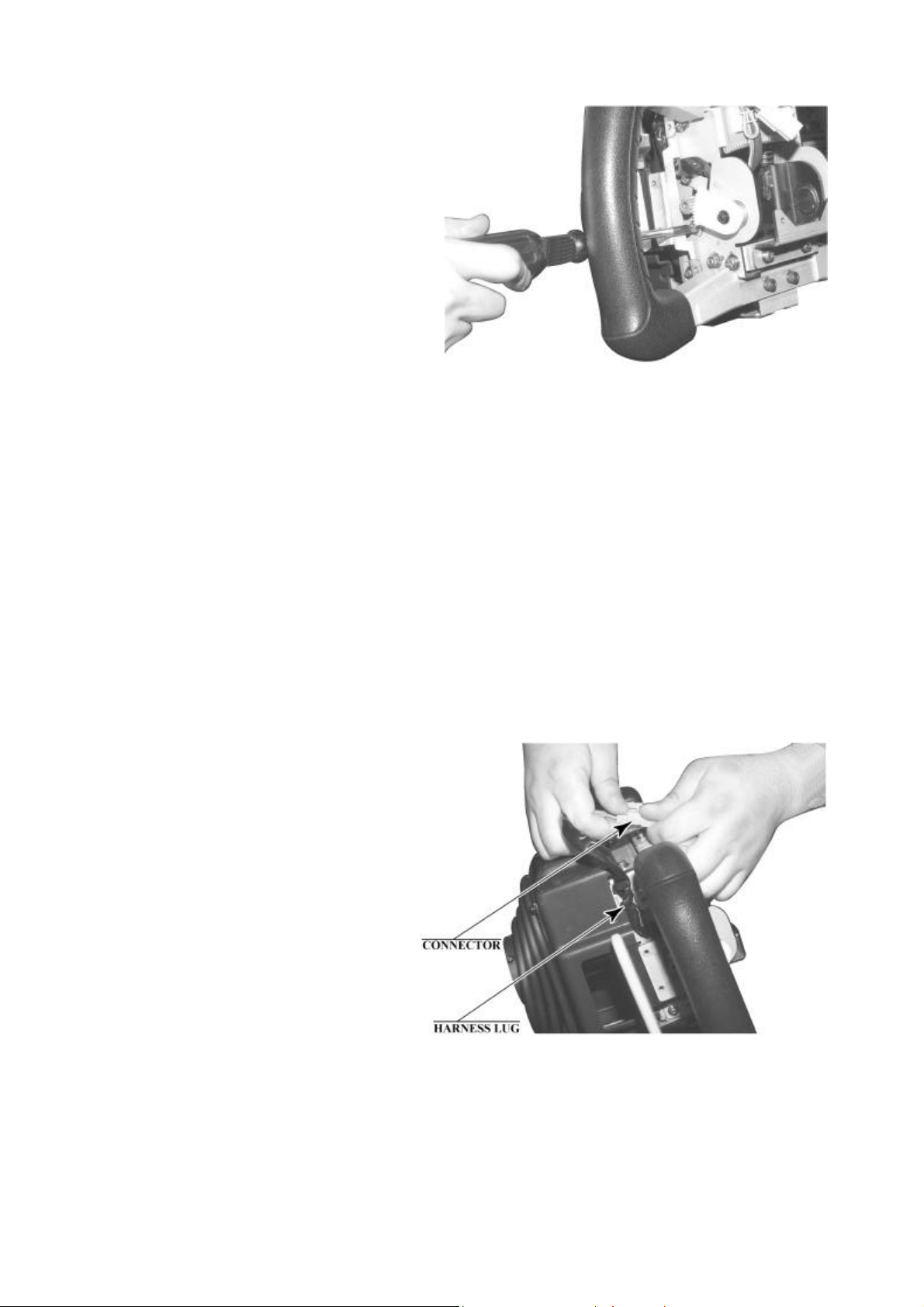
3.9.2.1.2.Replacement Procedure
1. Perform steps 1 through 7 under "Adjustment Procedure" to detach the front and rear steering
covers.
2. Unplug the Y-axis VR wire
connectors and unfasten the
harness lug holding the wiring in
place.
43

3. Remove the 2 screws holding the variable resistor bracket in place and then remove the Y-axis
VR, bracket and all.
4. Loosen the 2 hexagon socket
screws holding the gear in place
and disengage the gear from the
VR axle.
44

5. The wires connected to the old VR can be
reused for the new VR. Use the soldering iron to
melt the welds and remove the wires from the
VR.
6. Solder the wires to the new VR. Check the
wiring diagram to make sure there are no
mistakes in the wiring.
7. Attach the gear to the new VR.
8. Install the new Y-axis VR. Engage and secure the gear at such an angle that the D-cut side of the
VR axle is level and facing downward when the steering unit is not being tilted.
9. Manipulate the steering unit make sure the gear is turning smoothly.
10. Plug in the wiring connectors and secure the wires with the harness lug.
11. Repeat the above steps in reverse to replace the front and rear steering covers. Take care not to
pinch the wires or overtighten screws.
Note that the screws used to secure the left and right sides of the front steering cover have
different dimensions from the others. Check the screw sizes before installing them.
12. Adjust the variable resistor settings on the Volume Settings screen. (see .)
13. Check to make sure the "STEERING Y" value on the Input Test screen is within the range 78H+/8H.
45

3.9.2.2.Replacing The Microswitches
Movement in the steering unit's paddle levers is detected by 2 microswitches on the bottom of the interior
of the steering cover. Follow the steps listed below to replace or adjust the position of these switches.
Note that each of the 2 microswitches on the bottom of the steering unit is linked to the paddle on the
OPPOSITE side in the "PADDLE LEFT/RIGHT" test on the Input Test screen; that is, the microswitch on
the right controls the "PADDLE LEFT" value, and vice-versa. Check to make sure the switch being
replaced or adjusted is the correct one.
The following tools and instruments are required for the following operations:
• 3mm diameter hexagonal screwdriver or wrench
• M4-size Phillips screwdriver
• M3-size Phillips screwdriver
• Nippers
• Cutters
• Soldering iron
• Industrial dryer
3.9.2.2.1.Adjustment Procedure
1. Perform steps 1 through 7 for adjusting the Y-axis VR to remove the front steering cover and
detach the rear steering cover (see 3.9.2.1).
2. Loosen the 2 screws securing the SW ADJUST plate on which the microswitch to be adjusted in
installed, and then move the SW ADJUST plate to adjust it. Do not loosen the screws on the side
the microswitch is installed on.
46

3. Adjust the switch so that the roller on its actuator terminal touches the pin that interlocks with the
paddle lever when the lever is not being manipulated.
4. Tighten the 2 screws.
5. Manipulate the paddle lever to make sure the microswitches are turning on and off properly.
Listen for a clicking sound. Also, make sure that the switch does not adhere to the actuator itself
when turned on.
6. Replace the front and rear steering covers. Take care not to pinch the wires or over tight en the
screws.
Note that the screws used to secure the left and right sides of the front steering cover have
different dimensions from the others. Check the dimensions of the screws before installing them.
7. On the Input Test screen, check to make sure that the microswitches turn on and off consistently
when the paddle levers are manipulated (see 5.2.10.2).
3.9.2.2.2.Replacement Procedure
1. Remove the front steering cover and detach the rear steering cover (see 3.9.2.1).
2. Unplug the wire connectors from the
microswitch and unfasten the harness
lug holding the wires in place
3. Remove the 2 screws holding the SW ADJUST plate in place and then remove the microswitch
together with the SW ADJUST plate.
47

4. Remove the 2 screws securing the microswitch to be replaced and then remove the SW ADJUST
plate and the transparent insulation sheet.
5. The wires connected to the old microswitch can be reused for the new microswitch. Remove the
heat contraction tube covering the soldered areas, use the soldering iron to melt the solder, and
remove the wires from the microswitch.
6. Solder the wires to the new microswitch. Check the wiring diagram to make sure there are no
mistakes in the wiring. In addition, use a heat contraction tube or other protection to prevent
short-circuiting.
7. Attach the SW ADJUST plate and the insulation sheet to the new microswitch and secure them
with 2 screws. Be sure to insert the insulation sheet between the switch and the plate.
8. Install the SW ADJUST plate with the new microswitch in the bottom of the steering unit. Adjust
the position of the plate so that the roller on the microswitch's actuator terminal touches the pin
that interlocks with the paddle lever when the lever is not being manipulated, and secure it with 2
screws.
9. Connect the wire connectors and secure the wires with a harness lug.
10. Manipulate the paddle lever to make sure the microswitches are turning on and off properly.
Listen for a clicking sound. Also, make sure that the switch does not adhere to the actuator itself
when turned on.
11. Replace the front and rear steering covers. Take care not to pinch the wires or over tight en the
screws.
Note that the screws used to secure the left and right sides of the front steering cover have
different dimensions from the others. Check the dimensions of the screws before installing them.
12. On the Input Test screen, check to make sure that the microswitches turn on and off consistently
when the paddle levers are manipulated (see 5.2.10.2).
48

3.9.2.3.Greasing
• Be sure to use the designated type of grease. If a non-designated type grease is
used, components may break.
• Do not apply grease to any part of the machine other than those parts
specifically indicated. Doing so may result in malfunctioning and/or deterioration
Use spray grease once every three months to grease up the gear mesh portion of the constituent parts.
Use "Grease Mate" (part number 090-0066) for the spray grease.
of parts.
• The period for greasing specified herein is a standard. Apply greasing to the
specified portions as occasion arises.
49

3.9.3. Card Reader/Writer Unit
• Take care to work on the machine with the power turned off. In the powered
state, the machine may operate suddenly and can cause fingers to be pinched
or cut.
3.9.3.1.Setting Dedicated Cards
• Be sure to use dedicated cards available for this product. Use of ones other
than such dedicated cards may cause a malfunction or failure of the machine.
• Be sure to set the specified number of card in the specified orientation by
using the specified procedure. Wrong setting of the cards may cause the
machine to fail.
• This machine allows you to set up to 100 cards at a time. You must not set
over 101 cards at a time. If you do so, a trouble such as card jamming may
occur.
• Set virgin cards taken out from a container that was unpacked immediately
before use.
• Use of any deformed or deteriorated card may cause a trouble.
• Do not include a corrugated, bent, or used card in the card deck.
When the unit is out of cards, a message will be displayed at the upper right of the screen during
advertisements. Follow the instructions below to restock the system with cards. Cards may be stocked
when the unit is on or off.
After restocking the system with cards, the message displayed after the "SEGA" logo will be updated.
Gameplay can be resumed without waiting for the updated message.
Remove the truss screw
A) Unlock and open the cover to find the card reader/writer.
The dispenser on which you should place the cards is located at the rear of the reader/writer.
B) From the card reader/writer, take out the dispenser upward in a straight line.
50

Place the cards into the dispenser according to the instructions on the sticker attached to the dispenser.
C) Remove the cover from the back of the dispenser.
D)
Refer to the diagram shown on the sticker and insert the cards. Be careful not to insert the cards in the
wrong direction or with the wrong side facing up.
The Dispenser can only hold 100 cards. Do not attempt to insert more than 100 cards, as too many
cards may cause the Dispenser to jam or result in other problems.
Insert magnetic cards into the Dispenser in complete packs of 100 or after carefully counting the
number of cards (not to exceed 100).
E) Reinstall the cover to the dispenser.
F) Insert the dispenser into the card reader/writer. The dispenser can be inserted only in the
predetermined orientation.
G) Close and lock the cover.
H) Secure with the truss screw
51

3.9.3.2.Head Cleaning
the one outlined in
• The unit enters Head Cleaning Mode when any of the following conditions are
met:
• At power-up if the Card Reader/Writer has operated 100 times or more
• At power-up if the date has been updated
• At boot time after performing Backup Data Clear
• Once the unit enters Head Cleaning Mode, follow the on-screen instructions and
perform Head Cleaning. The unit will not exit Cleaning Mode (i.e. games may not
be played) until head cleaning is complete.
• Always use the designated Cleaning Card. Using anything other than the
designated card or carrying out any other procedure other than
the manual may cause faulty printing, faulty operation and/or unit failure.
• Cleaning Cards may only be used once. Dispose of them after use.
• Cleaning Cards should be used immediately after removal from the package.
Cleaning Cards will not clean effectively if dried out.
• Perform head cleaning only when there are cards in the Card Reader/Writer
Dispenser. If the Dispenser is empty, the part that secures the cards inside the
Dispenser may touch the rotating part of the Card Reader/Writer and cause
noise.
• Always remember to remove the Cleaning Card after completing head cleaning.
• After head cleaning, wait for the "SEGA LOGO" to be displayed at least twice
before resuming gameplay.
This machine records the number of times the Card Reader/Writer is used.
The Card Reader/Writer writes data to and reads data from cards. Each write and read is counted, so the
Card Reader/Writer usage count will not be the same as the number of times the game is played.
Once head cleaning of the Card Reader/Writer is complete, the unit will exit this mode.
Follow the on-screen instructions to carry out cleaning.
PLEASE INSERT CLEANING CARD
Insert the Cleaning Card into the card slot.
NOW CLEANING...
Indicates that the unit is undergoing cleaning. Wait for cleaning to be
completed.
The unit exits to normal mode after cleaning is complete.
Do not forget to remove the Cleaning Card.
Wait for the "SEGA LOGO" to be displayed at least twice before
resuming gameplay after cleaning.
The Card Reader/Writer usage count described above is reset when cleaning is performed.
Manual head cleaning may also be performed from Test Mode. Refer to Test Mode Section 5.2.10.6 for
more details.
52

3.9.3.3.Clearing Card Jams
When attempting to perform this operation without powering down so that
gameplay can be restored, exercise extreme caution. Machine parts may move
unexpectedly when the power is ON. This may result in fingers being caught or
severed and other injuries.
Verify the Stay Lock on the top cover before attempting this procedure. If the top
cover closes during the procedure, it may result in serious injury.
If a problem, such as card jamming, occurs on the card reader/writer it will be reported on the screen. Play
cannot proceed unless this problem is resolved. Identify the nature of the problem before any action is
taken.
If repeated attempts continue to generate errors, follow the instructions below to remove the card.
Removing the card may force the game to shut down. If the game shuts down, existing customer game
data will not be saved.
A) Remove the truss screw.
B) Unlock and open the cover.
C) Unlock the hatch by drawing the green
shaft attached to the top cover on the
card reader/writer. While drawing the
shaft, open the cover up.
D) Remove the card jammed in the card
reader/writer.
E) While drawing the shaft,
close the cover. With the top
cover closed, release the
green shaft. Check that the
top cover has been locked
securely.
E) Close and lock the cover.
F) Secure with the truss screw.
53

3.9.4. Accelerator & Brake
• Only Qualified Service Personnel must carry out maintenance. Ensure that the
mains power is switched OFF and disconnected before attempting any work.
In the TEST MODE, if the brake or accelerator V.R. variations are not within the allowable limit, the V.R.
installation position requires adjustment or the V.R. needs replacement. Also be sure to apply grease to all
moving parts every 3 months.
3.9.4.1.Removing the Accelerator & Brake.
1. Turn the POWER switch OFF
2. Remove a total of 4 screws securing the
covers over the ACCELERATOR & BRAKE
3. Fine adjustment of the V.R. values is
accomplished with just these covers
removed.
4. Coarse adjustment requires the
ACCELERATOR & BRAKE mounting bolts to
be removed. If this is necessary, remove the
bolts from the unit, but do not remove the
unit from the machine. Take extreme care
when operating the unit in this condition as
damage to other components can occur.
54

3.9.4.2.Adjusting the V.R.
• Never touch places other than those specified. Touching places other than
those specified can cause electric shock and short circuit.
• After the replacement or adjustment of the V.R. be sure to set the values in the
INPUT TEST.
The required values are:
GAS PEDAL: Under 30H
BRAKE PEDAL: Under 30H
(THE PEDAL
RELEASED)
1. Remove the cover panels as detailed above.
2. Fine Adjustment - By using a screwdriver
loosen the 2 machine screws that secure the
V.R. arm. Move the V.R. arm to adjust the V.R.
value within the relaxed range.
3. Coarse Adjustment - Remove the four hexagon
bolts detailed above and remove the side
covers of the Accelerator & Brake.
4. Loosen the two machine screws holding the
V.R. rack
5. Move the V.R. rack away so as to disengage
the V.R.
6. Gently rotate the V.R. until its value is within the
range of the centring position.
7. Mesh the gears together. Make sure that a
correct amount of backlash is maintained.
8. If the V.R. value is still not correct make fine
adjustments as detailed above.
⇒
⇒
Over C0H
Over C0H
(THE PEDAL
PRESSED)
55

3.9.4.3.Replacing the V.R.
1. Loosen and withdraw the V.R. rack as detailed above.
2. Using a hexagon key loosen the two grub screws holding the V.R. gear onto the V.R.
3. Remove the V.R. gear
4. Using a spanner remove the nut holding the V.R. in position.
5. Gently remove the V.R. and its wire harness.
6. Refit is the reverse of removal.
7. When complete you must readjust the V.R. in accordance with the paragraph above.
3.9.4.4.Greasing
• Be sure to use a good quality, synthetic lubricant. Using a mineral-based lubricant will
cause damage to the plastic parts.
• Do not apply lubricant to parts other than those specified. Doing so may cause
Apply lubricant to gear mesh portions once every 3 months.
damage or deterioration of parts.
56

3.10. Replacement Of Fluorescent Lamp And Other Lamps
• Never touch places other than those specified. Touching places other than those
specified can cause electric shock and short circuit. Disconnect the machine
from the supply before attempting the replacement of any lamp.
• Prepare a secure step when working on the upper parts of the machine.
• Only QUALIFIED SERVICE PERSONNEL should replace lamps.
3.10.1.Fluorescent Lamp Replacement
1. Turn the POWER switch OFF.
2. Take out the 3 screws and open the Billboard lid.
3. Remove the end caps from the fluorescent tube.
4. Pull the tube out of the clips with a twisting
action.
57

3.11. Cleaning The Cabinet Surfaces
When the cabinet surfaces are badly soiled, remove stains with a soft cloth dipped in water or diluted
(with water) chemical detergent and squeezed dry. To avoid damaging surface finish, do not use such
solvents as thinner, benzine, etc. other than ethyl alcohol, or abrasives, bleaching agent and chemical
dustcloth.
3.12. Seat (Greasing To Seat Rail Portion)
Move the Seat to the rearmost position
and apply spray greasing to the portion
shown at the right once every 3 months by
using NOK KLUBER L60 or GREASE
MATE SEGA PART No. 090-0066.
After greasing, move the Seat a few times
forward and backward so as to allow the
grease to be applied all over uniformly. Be
sure to wipe grease which attaches to the
surfaces of the PROTECT RUBBER on
the Seat Rail, or any excess grease.
58

3.13. Troubleshooting
• Only QUALIFIED SERVICE PERSONNEL should carry out these procedures.
3.13.1.Card Reader/Writer
If this machine detects an error during the operation of the Card Reader/Writer, it will display the error
messages listed below. Perform the appropriate maintenance based on the content of the error message
displayed.
Should an error occur, do not attempt to open the top cover of the Card Reader/Writer. The unit will
attempt to save the data to the customer's card and restore the game if the top cover is closed and the
RESTORE command (hold down the Start button + Change View button for a short time) is used.
However, attempting to use the RESTORE command after the top cover has been opened may force the
game to shut down and not save data to the card.
When the game shuts down or the unit is reset, the data on the customer's card is not saved. In order to
save customer data, perform the proper maintenance carefully.
ERROR DISPLAY CAUSE COUNTERMEASURES
Error occurred while reading
card. Card will be ejected
without saving data. Please
press the Start and Change
View buttons.
Error occurred while saving
data. Please notify a store
attendant. Please press the
Start and Change View
buttons.
Printing error. Card will be
ejected without printing or
saving data. Please press
the Start and Change View
buttons.
A shutter error has
occurred. Please remove
any cards present in card
insertion slot. Please press
the Start and Change View
buttons.
This card cannot be used.
Card will be ejected without
saving data. Please press
the Start and Change View
buttons.
Card jam. Ejecting card.
Please press the Start and
Change View buttons.
This message is displayed after
several failed attempts to save data
to the card at the end of the game.
This message is displayed after
several failed attempts to print at the
end of the game.
This message is displayed after
several failed attempts to read the
card at the end of the game.
This message is displayed when the
shutter is forced open or if the unit
detects a problem with the shutter.
This message is displayed when the
unit is unable to open/close the
shutter.
This message is displayed when the
card in the Card Reader/Writer is not
a proper player card at the end of the
game.
This message is displayed when
various operations fail because of
dirty rollers or heads.
Press the Start button and Change View
button at the same time to eject the card and
end the game.
Leave the card in place and press the Start
button and Change View button at the same
time to retry the save operation.
Remove the card and press the Start button
and Change View button at the same time to
restore or end the game.
If this error occurs several times, use Test
Mode to perform manual cleaning. (See
Cleaning Section 3.9.3.2)
Press the Start button and Change View
button at the same time to eject the card and
end the game.
Correct the problem, then press the Start
button and Change View button at the same
time to restore the game. Circumstance may
force the game to shut down.
Correct the problem, then press the Start
button and Change View button at the same
time to restore the game.
Press the Start button and Change View
button at the same time to eject the card and
end the game.
Press the Start button and Change View
button at the same time to eject the card and
restore the game.
If this error occurs several times, use Test
Mode to perform manual cleaning. (See
Section 3.9.3.2)
59

Continued from previous page
ERROR DISPLAY CAUSE COUNTERMEASURES
There is a problem with the
card reader/writer. Please
notify a store attendant.
Please turn off the power
and start again.
The card reader/writer is not
responding. Please notify a
store attendant. Check the
card reader/writer is
connected properly, turn off
the power and start again.
SCIF Error. Please notify a
store attendant. Check that
the card reader/writer is
connected properly, turn off
the power and start again.
Card jam. Remove the card
and press the Start and
Change View buttons. If the
card cannot be removed,
please notify a store
attendant.
This message is displayed when
there is a problem with the Card
Reader/Writer and it sends improper
signals.
This message is displayed at powerup during advertisements when the
Card Reader/Writer is not connected
properly or when it is broken and
unresponsive.
This message is displayed when a
communication error occurs between
the Card Reader/Writer and the
game board.
This message is displayed when
various operations fail because of
dirty rollers or heads.
Verify there are no problems with the
shutter and that the top cover is closed
and then restart the unit.
Verify that the Card Reader/Writer is
connected properly and then restart the
unit.
Verify that the Card Reader/Writer is
connected properly and then restart the
unit.
If this error occurs several times, check
the immediate area for sources of
possible interference.
Leave the card in place and press the
Start button and Change View button to
retry the operation.
Remove the card and press the Start
button and Change View button at the
same time to restore or end the game
(refer to 3.9.2).
If this error occurs several times, use
Test Mode to perform manual cleaning.
This message is displayed when a
card jam is suspected when there
should be no card in the Card.
Press the Start button and Change View
button at the same time after removing
the card or correcting the problem to
restore the game.
60

The following error messages are displayed when problems are detected during unit power-up (during
prompting an automatic Card
attempting to do so, the Card
initialization of the Card Reader/Writer). Perform the appropriate maintenance based on the content of the
error message displayed.
ERROR DISPLAY CAUSE COUNTER MEASURES
CARD R/W ERROR! This message is displayed at
power-up when the Card
Reader/Writer is not
connected properly or when
it is broken and
unresponsive.
PLEASE INSERT CLEANING CARD. This message is displayed
when the conditions
Reader/Writer cleaning are
met.
PLEASE WAIT This message is displayed
during network setup while
the other unit is being
initialized.
CAN'T EJECT
This message is displayed at
power-up when, after
Reader/Writer is unable to
eject a card for some reason.
This message is displayed at
power-up when the shutter
cannot be opened/closed
properly.
Verify that the Card Reader/Writer is
connected properly and then restart
the unit..
If broken, contact the company from
whom the unit was purchased.
Perform the Card Reader/Writer
cleaning. (See 3.9.3.2)
This message disappears once
initialization of the other network
game unit is complete.
Remove all cards from the Card
Reader/Writer. (See 3.9.3.)
Verify that there are no problems with
the shutter and then restart the unit. If
this error occurs several times,
contact the company from whom the
unit was purchased.
The following messages are displayed when there are limits to the Card Reader/Writer Operation Mode.
The messages are displayed in the upper right of the screen during advertisements. The message content
is updated after the "SEGA LOGO" is displayed.
If the message is not one displayed intentionally by the Operation Mode, perform the appropriate
maintenance based on the content of the error message displayed.
ERROR DISPLAY CAUSE COUNTER MEASURES
The machine is currently
unable to issue new cards.
Please see a store attendant to
have the machine restocked
with cards.
Cards may not be used at this
time.
The Card Reader/Writer
Dispenser is empty (no cards).
Cards may not be used due to
the Store Closing setting being
activated.
Restock the Dispenser with cards.
(See 3.9.3)
If no cards are available, contact the
company from whom the unit was
purchased
If there is a mistake in the settings,
use Test Mode to change the Store
Closing setting.
If the setting is correct, but not
operating properly, check the internal
clock settings on the game board
(Refer to the Service Manual.)
61

3.13.2.Troubleshooting (When No Error Message Is Shown)
cent lamp and the
• In order to prevent electric shock and short circuit, be sure to turn power off
before performing work.
• Be careful so as not to damage wirings. Damaged wiring can cause electric shock
or short circuit.
• After removing the cause of the functioning of the Circuit Protector, reinstate the
Circuit Protector. Depending on the cause of the functioning, using the Circuit
Protector as is without removing the cause can cause generation of heat and fire
hazard.
• In the event that a problem cannot be resolved by employing the procedures
listed in this Manual, be sure to request service from the office shown on this
Manual or the dealer from whom the product was originally purchased. Attempts
to employ procedures other than those specified in this Manual can cause
electrical shock, shorting, or fire.
• In the event of a problem that is not described here, be sure to contact the office
shown on this Manual or the dealer from whom the product was originally
purchased. Careless attempts at repair can result in electrical shock, shorting, or
fire.
If a problem occurs, first check to make sure that the wiring connectors are properly connected.
PROBLEM CAUSE COUNTER MEASURES
When the main SW is
turned ON, the machine
is not activated.
Fluorescent lamp inside
FL box doesn't light up.
The power is not ON. Firmly insert the plug into the outlet.
Incorrect power source/voltage. Make sure that the power
supply/voltage are correct.
The fuse of the connect board was blown
out due to momentary overcurrent.
Connector connection fault. Check connector connections
Fluorescent lamp and Glow lamp need
replacement.
After eliminating the cause of
overload, replace the specified rating
fuse.
between the Cabinet and the FL box.
Replace the fluores
glow lamp (See Section 3.10)
62

Irregular/uneven colors on
The power source and voltage are no
PROBLEM CAUSE COUNTER MEASURES
Sound is not emitted.
Sounds are emitted and
the lamps are lit, but the
screen is black.
the monitor screen.
Colors on the monitor
screen are strange.
The on-screen image
sways and/or shrinks.
Does not accept input
from any switch or
volume.
Sound volume adjustment is not
correct.
Faulty connections for various
connectors.
Malfunctioning BD, Amp. and
Speaker.
Faulty connections for the visual
signal connector or the monitor
power connector.
Broken monitor. Contact the company from whom the unit
Magnetization of the CRT. Press the Degauss. switch on the VTS
Faulty connection for the visual
signal connector.
Screen adjustment is not appropriate. Make adjustment appropriately. (See
correct.
Faulty connector connections.
Adjust the Switch Unit's sound adjustment
volume.
Check the connections for the game board,
amp, speakers and Volume connectors.
Perform SOUND TEST. (See 5.2.5)
Check the connections for the monitor and
game board connectors.
was purchased.
Assembly (See Section 5.1.1.)
Check the visual signal connector
connection and make sure it is secured
properly.
Monitor Manual)
Make sure that the power supply and
voltage are correct.
Check the connection for the I/O Board and
Cabinet connector.
Check the power for the I/O Board.
STEERING (Servomotor)
response is incorrect.
Incomplete power on check. Power on and verify that the power on
check completes properly. (See 3.7.8 )
Deviation of the volume value. Adjust the volume value in the Test Mode.
Volume gear engagement fault. Adjust the engagement of the gear. (See
Sections 3.9)
Volume malfunctioning. Replace the volume. (See 3.9.)
Detached wires. Check for faulty wire connections around
moving parts.
When replacing wires, secure them so that
they do not touch any moving parts.
63

Momentary overload caused a fuse
PROBLEM CAUSE COUNTER MEASURES
No response from Steering
(Servomotor).
Steering (Servomotor) is
week in its force feedback.
Unsatisfactory Accel and
Brake operation.
Failure of power-on checking
procedure.
Reconnect the power and complete a
power-on checking procedure. (See
Section 3.7)
Faulty connector connections. Check the connections for the connectors
between the Game Board and
Servodriver and between the Servodriver
and the Servomotor.
Thermal element in the
Servodriver is operating.
Occurs when the internal temperature
reaches 70°C (158°F) and corrects
automatically when the unit cools.
Contact the company from whom the unit
on the Servodriver to blow.
Aging of the force feedback
was purchased.
Reset in the Test Mode.
mechanism.
Incorrect volume setting. Adjust the volume value in the Test
Mode. (See Section 5.)
Faulty Volume attachment or
adjust gear alignment.
Adjust the volume attachment and verify
in Test Mode. (See Section 5.)
Faulty connector connection. Check the connections for the Accel and
Brake connectors and the connectors
between the Accel, Brake and Cabinet.
Start button and Change
View button input does not
work and they do not flash.
Start button and Change
View button input works,
but they do not flash.
Failure of the network play.
Failure of the volume. Replace the volume.
Faulty connector connections. Check the connections for the connectors
between the I/O Board, the Cabinet and
the Control Panel and those inside the
Control Panel.
Unverified settings or operation. The Start button only flashes when Free
Play is set. Check the operation in Test
Mode.
(See Section 3.9)
The lamp is burnt out. Replace the lamp.
Network play is wrongly set. Reset correctly. (See Section 5)
Communication cables are wrongly
connected.
Reconnect the cables.
(See Sections 3.7 and 5)
Communication cables are
disconnected.
Damage of communication cables.
Reconnect cables correctly. (See Section
5)
Replace the cables. Contact the
company from whom the unit was
purchased.
64

3.14. Gameboard
• Turn off the mains power and remove the power cord before opening the machine.
• The GAME BOARD should not require any work to be carried out upon it. All settings
and tests can be achieved without access to the GAME BOARD.
• All work to be carried out by QUALIFIED SERVICE PERSONNEL
3.14.1.Removing The Board
To return the game board for servicing, take out the board using the following procedure.
1. Turn the main switch OFF.
2. Unlock the base and remove the 2 M6 bolts.
3. Tip the seat carefully backwards as shown. Be careful not to damage the seat back when resting it on
the floor. Use a protective mat under the seat back to protect it on hard floors.
4. Disconnect all connectors from the game board, remove the four screws securing the game board to
the wooden base, and lift it out. Do not attempt to service the game board. THERE ARE NO USER
SERVICEABLE PARTS INSIDE! Return the game board to the Service Department inside the special
packaging provided.
65

3.14.2.Removing The GD-ROM Drive
1. Turn the power off.
2. Remove 1 truss screw from each side of Base Lid R.
3. Unlock the base with the Master Key.
4. Turn the Lock Handle on Base Lid R to unlock the lid.
5. Lower the seat towards the backrest. Slowly lower the backrest until it touches the floor to prevent
damage to the seat part. Put a drop cloth on the floor to prevent damaging the surface of the seat
part.
6. Remove the GD cable connector and the power cord connector from the GD-ROM drive.
66

7. Remove the 4 screws to remove the GD-ROM drive.
67

3.14.3.Removing The Game Board (Triforce)
• When returning the game board for replacement or repair, make sure that the
connectors are attached correctly. Incorrect connections can lead to accidents such as
electric shock, short circuits, and/or fire.
• When plugging in connectors, pay close attention to the direction of the connection.
The connectors are designed to be connected in a specific direction. Attempting to
plug in a connector by applying excessive force may damage the connector or its
terminal clasp, possibly resulting in electric shock, short circuits, and/or fire.
1. Follow the above described action 1 to 5.
2. Remove all the connectors from the TRIFORCE.
3. Remove the 3 screws that fix the Game Board.
68

3.14.4.Composition Of The Game Board
• With the key chip installed, the TRIFORCE board becomes a proprietary game board
for this product.
ASSY TRF FZR USA (842-02DD511U): USA
ASSY TRF FZR EXP (842-02DD511E): OTHERS
ASSY TRF FZR ASIA (842-04DD511E): ASIA
3.14.4.1.DIP SW Setting
Use this product with the DIP SW settings shown in the figure below.
69

3.14.5.Replacing The Main Board Battery
• To prevent overheating, explosion, or fire:
• Do not recharge, disassemble, heat, incinerate, or short the battery.
• Do not allow the battery to come into direct contact with metallic objects or other
batteries.
• To preserve the battery, wrap it in tape or other insulating material.
• Follow local regulations when disposing of the battery.
• Improper disposal can damage the environment.
• To avoid risk of malfunction and damage:
• Make sure the positive and negative ends are aligned correctly.
• Use only batteries approved for use with this unit.
• If an error appears indicating that the battery power is very low within the first year of
use, it is usually an indication of a problem or abnormality with something other than
the battery. Be sure to inspect the board that the battery is connected to.
1. Remove the 5 screws holding the TRIFORCE and its cover in place.
2. Slide the cover off of the TRIFORCE, being careful of the hook that holds them together.
70

3. Gently remove the battery from the battery holder. The battery holder is located on the very
bottom of the main board.
4. Insert the new battery (CR2032) so that the + terminal is pointing upward.
Removed batteries should be disposed of in accordance with relevant national laws and/or local
regulations.
TRIFORCE MAIN BOARD BATTERY
SEGA PART No.: 401-0065
SEGA PART NAME: BATTERY CR2032 HITACHI
71

3.14.6.Replacing The DIMM Board Battery Pack
3.14.6.1.Warnings And Restrictions Concerning The Battery Pack
Observe the following precautions when handling the DIMM board's battery pack. Sega cannot assume
responsibility for any problems that arise from handling the battery pack in disregard of the guidelines set
forth in the manual.
• Do not disassemble the battery pack and the batteries.
• If you should fail to observe this instruction, the internal wires and/or protective
devices may be damaged; as a result the safety system may not function when
discharging and recharging, eventually causing an over heating, fire and explosion. If
you should disassemble the batteries, the generated gases may harm your throat and
the negative plate may overheat and make a fire.
• Do not make an external short circuit of the battery pack and the batteries.
• If you should fail to observe this instruction, the batteries may overheat, make a fire,
and explode.
• Do not fire the battery pack and the batteries.
• If you should fail to observe this instruction, the batteries may make a fire and
explode.
• Do not leave the battery pack and the batteries nearby the heat source (fire or heater)
or under the intense direct sunlight and flaming sun. If you should fail to observe this
instruction, the batteries may reduce the service life and in the worst case may
overheat, make a fire, and explode.
• Do not leave the battery pack and the batteries in water or seawater. Also do not apply
water or seawater onto the battery pack and the batteries. If you should fail to observe
this instruction, the internal wires and/or protective devices may be damaged; as a
result the safety system may not function when discharging and re charging,
eventually causing an overheating, fire and explosion. Also water may be electrolyzed
into oxygen and hydrogen, and eventually the battery's sealed section may be
corroded and the internal liquid may leak.
• Do not solder on the battery pack's terminals.
• If you should fail to observe this instruction, the armor may be heated and melted or
the internal wires may be damaged, eventually causing an overheating, fire and
explosion. Also, when the battery's temperature reaches to 100C or more, the battery
may leak its internal liquid due to destruction of its plastic parts (gasket, separator,
etc.), or may overheat, make a fire, or explode due to internal short-circuit.
• Do not insert or connect the battery in a reversal polarity.
• If you should fail to observe this instruction, the battery may be externally short-
circuited and eventually overheat, make a fire, or explode, depending on the device
you connect with.
72

• Do not tightly seal the battery pack when installing it onto an external device.
• Flammable gas is generated from the battery when its safety mechanism has
functioned. If you should fail to observe the above-described instruction, sparks from
motors, switches, etc. may cause the gas to fire. Therefore, install the battery pack so
that the gas can be quickly released from the external device.
• Do not use the battery pack for the device/usage other than this game system.
• If you should fail to observe this instruction, the battery and/or the device may be
damaged due to non-applicable specifications.
• Do not strike a nail in, hammer, step on, or apply any other forms of pressures and
shocks on, the battery.
• If you should fail to observe this instruction, the battery may be deformed. As a result,
the battery may burst at its sealed sections to leak the internal liquid, or may be shortcircuited internally to overheat, make a fire, and explode.
• Do not use a battery charger because any battery charger is not usable for this battery
pack.
• If you should fail to observe this instruction, the gas may be suddenly generated in the
battery and eventually the battery may overheat, make a fire or explode.
• If the battery in use or in keeping shows an abnormal indication (deformation, change
of colour, bursting of the armour cover, etc.), immediately stop using or keeping it. If it
leaks and smells abnormally, immediately keep it away from fire and put it in a safety
box.
• If the liquid leaks from the battery and gets in your eyes, do not rub your eyes but
immediately wash them with clean water (city water etc.); and consult a medical doctor
for a treatment. If you should fail to observe this instruction, the liquid may harm your
eyes.
• The battery pack armour (a polyvinyl chloride tube) may be damaged or deformed by
external force or heat. When transporting the battery pack or replacing it with a new
one, therefore, be careful not to drop or excessively shock it. Do not continue to use
any damaged or deformed battery pack. If you should fail to observe this instruction,
the battery may overheat, make a fore, or explode.
• The battery pack contains a printed circuit board (PCB) for protective circuitry. It may
be destroyed by the static electricity. When handling or servicing the battery pack,
therefore, take preventive measures against the static electricity.
• If your battery pack has shown destruction of a protective circuitry PCB, do not
continue to use it. If you should fail to observe this instruction, the battery may
overheat, make a fore, or explode.
• When wiring the battery pack to a device, be careful not to apply excessive force onto
the connectors and lead wires. The battery may overheat, make a fire, or explode if
the connectors and lead wires are damaged.
• Do not do away with the used battery packs carelessly because they may contaminate
the environment. Submit them to an industrial waste disposal plant.
• Be sure to dispose of the used battery pack in accordance with relevant national laws
and/or local regulations.
73

If the GD-ROM drive appears to be taking too long to read the disc, the battery pack on the DIMM board
may need replacing. The battery pack should last approximately 16 months under normal usage.
There is no recharging unit for the battery pack.
Follow the steps listed below to replace the battery pack.
1. Follow steps 1 and 2 in Section 3.14.5 to remove the cover.
2. Unplug the battery pack's connector.
3. Remove the single tapping screw and slide the battery holder cover to remove it.
4. Remove the battery pack.
5. Repeat the above steps in reverse to install the new battery pack.
The used battery pack is considered industrial waste.
As such, it should be disposed of in accordance with relevant national laws and/or local regulations.
DIMM BOARD BATTERY PACK
SEGA PART No.: 401-0081
SEGA PART NAME: BATTERY PACK CGR-B/246A
74

3.14.7.Shipping The Game Board And GD-ROM Drive
Observe the following precautions when sending the TRIFORCE or GD-ROM drive out for servicing or
repairs.
The carton boxes (included) are needed to ship these parts, and should therefore be stored in a safe place
to ensure that they are not lost.
• When sending parts in for repairs, they should be configured as follows:
(1) TRIFORCE:
- Leave the key chip installed in the board.
(2) GD-ROM drive:
- Remove the drive bracket.
- Eject the GD-ROM disc, place it in its case, and store in a safe place.
• Remove the wire harnesses and cables from the TRIFORCE and GD-ROM drive before sending
them in for repairs.
• Do not disassemble the TRIFORCE or GD-ROM drive. Place them in the carton box as is when
sending them in for repairs.
• Provide a clear, detailed description of the game used and the observed problems when sending
to the indicated repair center.
3.14.7.1.How To Use The Triforce Carton Box
Fold the packaging in the order specified in the diagram and wrap it around the TRIFORCE, making sure
that board and box are aligned correctly. Finally, place it in the carton box.
Failure to wrap the product as specified in the diagram may cause damage to parts.
75

3.14.8.Machine Set Up
During linked play, if the test mode is not finished within three minutes on all linked machines, the
NETWORK CHECK cannot be performed, causing a NETWORK ERROR.
First, set up each linked machine to meet the requirements of communication play. If the settings are
incorrect, communication play is not possible.
76

3.14.8.1.Network Play
Up to 4 machines can be linked for network play. Properly connected network cables and correct network
play settings are required for network play.
3.14.8.1.1.Precautions Regarding Network Play Setup
• Before starting to work, ensure that the Power SW is OFF. Failure to observe this
can cause electric shock or short circuit.
• Use care so as not to damage wirings. Damaged wiring can cause electric shock
or short circuit.
• Do not touch undesignated places. Touching places not designated can cause
electric shock or short circuit.
• This work should be performed by the site maintenance individual or other skilled
professional. Performing work by non-technical personnel can cause electric shock
hazard.
• When linking a number of machines, be sure to supply sufficient power for the
corresponding number of machines. Be sure to secure per machine current as
stated in this manual. Failure to observe this can cause a fire and an electric shock
accident.
• Due to the length of the network cable, the distance in between the machines is
limited. However, to avoid accidents, be sure to secure space in excess of 70 cm
between the machines.
• To perform work safely and avoid serious accident such as the cabinet's falling
down, do not perform work in places where step-like grade differences, a ditch, or
slope exist.
• To perform work safely, be sure to secure the space corresponding to number of
machines to be linked. Failure to observe this can cause accident.
• To avoid accidents, use a cable cover that will not cause patrons to trip when laying
network cables in areas of heavy foot traffic.
• To prevent accidents and acts of vandalism, cover the network cables with the
strongest cover possible.
• Network play is not possible between game machines with different cabinet types.
When connecting several games machines together, make sure that a sufficient amount of electrical power
is available for each machine. Plan on providing 15A for each machine in 100-120V locations, and 7A in
220-240V locations.
77

3.14.8.1.1.1.Spacing of Game Machines
Leave at least 70 cm of space between game machines.
78

3.14.8.1.2.Connecting Network Cables
To enable network play, the hubs inside each of the game machines involved must be connected with
network (LAN) cables. Connect the hub inside one of the machines to the hub in the other machine using
LAN cables. There is no need to connect the other machines to each other in any other way.
Do not connect LAN cables between twin machines when they are not used for network play.
1. Turn off the power and unplug the power cord from the outlet. Place the power cord so as not to
damage it while working.
2. Using the illustration on the previous as reference, move the machines so that they are lined up.
Leave enough space on the front lid side of the machine to perform the rest of the operations in
this procedure.
3. Remove the lower back lids of machines denoted ‘L’ on back.
4. Remove the front covers on both machines.
5. Take off the required hole lids at the ends of the AC covers (see diagram above).
6. Route a spare LAN cable through both machines connecting both hubs.
Any of the ports 2 or above can be used to connect to any of the other game machines.
7. Replace all lids and covers.
8. Once the machines have been linked for network play, line them up. Leave as much space as
possible between the machines.
9. Secure all adjustors on each machine. (See Section 3.7.3)
10. Connect the power cord and grounding wire for each machine. (See 3.7.8)
79

3.14.8.1.3.Network Play Settings
Each of the linked machines must be set up for network play. If the machines are not set up correctly,
network play will not be possible.
3.14.8.1.3.1.How To Set Up A Machine For Network Play
1. Turn off the power on each machine to be used in network play.
2. Enter Test mode on each machine. (See Section 5.1)
3. Select GAME TEST MODE and press the TEST Button. The machine will enter Game Test mode
and the screen will display the Game Test menu. (See Section 5.2.10)
4. Select NETWORK SETTINGS from the Game Test menu and press the TEST Button. The
Network Settings screen will appear. Network settings are carried out on this screen.
NETWORK SETTING
LINK NUM 2(2•`4)
GROUP A(A•`Z)
NUMBER 2(1•`4)
-> EXIT
SELECT WITH SERVICE BUTTON
AND PRESS TEST BUTTON
5. Set the LINK NUM setting on the Network Settings screen to the number of game machines linked
for network play.
6. Set up the GROUP setting on the Network Settings screen. The GROUP setting is used to divide
the machines linked for network play into groups. For example, a network of 4 machines could be
divided into 2 groups of 2 machines.
7. Set the NUMBER setting on the Network Settings screen so that each machine within a group has
a different number. Make sure that one machine in each group is set to "1".
8. Exit Test mode on each machine. Be sure to choose EXIT from the System Test Menu to exit Test
mode properly.
9. Once each machine has exited Test mode and gone through initialization, it will begin a network
test. During the network test, the monitor will display a network test screen.
10. If there are no problems with network play settings or cable connections, the machine will enter
Advertising mode.
11. If the advertising screen appears after the network test is finished, network settings are complete.
12. The network test should last roughly 20 to 30 seconds. If the network test screen fails to disappear,
the problem is most likely due to one of the following: incorrect settings, an improperly connected
LAN cable, a faulty LAN cable connection, or a severed wire.
80

3.14.8.1.4.General Precautions Regarding Network Play
• When setting up machines for network play, settings such as the game's difficulty
level will be derived from the machine whose "NUMBER" is set to "1". If settings on
machine "1" are changed, the other machines will have their settings changed
accordingly. On machines other than "1", settings derived from machine "1" will not
be displayed on screen and cannot be changed.
• Should a network connection fail during network play, gameplay will be suspended
and the Network Error Screen will be displayed.
• If one of the units attached for network play enters Test Mode, the other unit will
display the same Test Mode Screen.
• Even when units are connected for network play, each seat, each game may be
given different cost settings. Incorrect cost settings may cause budget balancing
problems.
Note that when 2 or more machines are linked together for network play, some functions are different than
for stand-alone machines.
Whenever Test mode is used on a machine linked for network play, all machines connected to the network
will display the network test screen. When patrons are engaged in network play, do not enter Test mode on
any of the machines in the network, even if the machine is not in use.
However, machines whose GROUP setting is different from that of the machine entering Test mode will
not be affected.
81

3.15. Periodic Check And Inspection
The items listed below require periodic check and maintenance to retain the performance of the machine
and ensure safe operation:
• Be sure to check annually to see if the power cords are damaged. The plug is
securely inserted and that there is no dust in the interior of the machine or
between the socket and the power cord. Using the product in an unclean
condition may cause a fire or electric shock.
• Only QUALIFIED SERVICE PERSONNEL should carry out periodic checks.
The items listed below require periodic check and maintenance to retain the performance of this machine
and to ensure safe business operation.
When handling the controller, the player will be in direct contact with it . In order to always allow the player
to enjoy the game, be sure to clean it regularly. Also, it is advisable to provide wet tissue, etc. available for
player use.
ITEMS DESCRIPTION PERIOD
CABINET Check Adjusters' contact with surface. Daily
CARD READER/WRITER Head cleaning Every 151 counts of the card
reader/writer or Daily
CONTROL PANEL
COIN CHUTE DOOR
SEAT Greasing to the seat rail Tri-monthly
POWER SUPPLY PLUG Inspection and cleaning Annually
INTERIOR Cleaning As necessary
CABINET SURFACES Cleaning As necessary
Cleaning As necessary
Inspection of VR Monthly
Inspection of adjusting gear mesh Tri-monthly
Greasing Tri-monthly
Inspection of SW Monthly SHIFT LEVER
Greasing Tri-monthly
Inspection of VR Monthly ACCEL. & BRAKE
Gear and Spring portion greasing Tri-monthly
SCREEN cleaning. Weekly MONITOR
Check adjustments. Monthly or when moving.
Inspection of COIN SW Monthly
Coin insertion test Monthly
Cleaning of COIN SELECTOR. Tri-monthly
MEMORY TEST Monthly GAME BD
Check settings. Monthly
82

4. HOW TO PLAY
4.1. Game Description
The following explanations apply to the case the product is functioning satisfactorily. Should there be any
moves different from the following contents, some sort of faults may have occurred. Immediately look into
the cause of the fault and eliminate the cause thereof to ensure satisfactory operation.
Whenever power is flowing to the machine, the fluorescent lamp is lit up. While in Advertising mode, the
monitor will go through an advertising display loop, explaining the game's content and card system,
displaying the rankings, and so on.
Sound is output from the speakers to the left and right of the monitor and on the left and right of the seat's
headrest. Sound output during Advertising mode can be turned on or off by adjusting the corresponding
setting in test mode.
The "Start" button and the 4 "View Change" buttons on top of the control panel are able to light up. They
are not lit during Advertising mode.
The "Start" button will blink when enough credits have been inserted to play the game, and cease to blink
when it is pressed to start the game. If there are still enough credits to play again after the game ends, the
button will begin to blink again. After the race starts, the "View Change" button corresponding to the
currently selected view will light up; all the others will remain unlit.
83

1 START BUTTON: start game
2 STEERING UNIT: control direction
3 BOOST BUTTON: accelerate
4 LICENSE CARD SLOT
5 VIEW CHANGE BUTTON (1 - 4)
6 PADDLE LEVER: control centre
of gravity (while driving)
7 MEMORY CARD SLOT
8 BRAKE PEDAL: brake
9 GAS PEDAL: control speed
4.1.1. Game Outline
This product is a racing game. It has two modes, RACE MODE and TIME ATTACK MODE. When the
cabinets are connected (up to four cabinets), VERSUS PLAY is available. The game features six courses
from which the players can choose freely. Each course has a time limit, and if you don't reach the goal
within the time limit, your time is up and the race will end. Passing through checkpoints and control lines
increases your time. Each course has a different number of checkpoints. A time penalty occurs when the
player leaves the course and when his car explodes (energy goes to zero).
F-ZERO LICENSE CARD
You can receive your very own machine by purchasing a license card at the start of play. You can save
player data to the card, including your name, pilot rank, pilot points, and time attack records. 1st-place data
and numbers of wins are also recorded on the card.
Pilot Points
Use your license card to earn pilot points based on your play in Race and Time Attack Modes. Once you've
collected enough points, you can get custom parts to customize your machine with!
Pilot Rank
Your pilot rank increases based on your play. Your rank can never decrease in this game.
NINTENDO GAMECUBE MEMORY CARD
Use your Memory Card to link the game with F-ZERO GX for Nintendo GameCube. But in order to use this
special feature you must have F-ZERO GX game data on your card. Please note that the game cannot link
with a Memory Card that does not contain F-ZERO GX game data.
84

4.1.2. Game Mode
Race Mode
A single-course race. Thirty machines go head to head for first place. In linked play, players can go headto-head against other players.
When using a license card, the game ends when the player takes first place on every course.
Time Attack Mode
Race a set number of laps in time-trial format and fight for the best total time record. Ghost play is also
available.
Internet rankings via PC are also planned. A license card is needed for Internet rankings.
Internet Rankings
When PASSWORD DISP is set to OFF, the Internet Rankings guide is not shown during advertising.
When it is set to ON, a password is shown after playing Time Attack. Enter this password with a PC to join
the F-ZERO Internet Rankings.
The rankings will be available on the F-ZERO Official Home Page (http://f-zero.jp/).
4.1.3. Playing the Game
4.1.3.1.The Card Check Screen
If you already have a license card, place it in the License Card Slot to continue automatically to the next
screen. You can insert the Memory Card in this screen as well, but if you do not insert the Memory Card
before the license card, it will not work properly.
85

4.1.3.2.The F-Zero License Card Screen
Press down on the accelerator in the Card Check Screen to move to the Purchase Screen. When creating
a new card, insert the required number of coins to make a new license card. When your license card's
credits have been used up, you will be moved to the Renewing Purchase Screen.
You can insert the Memory Card in this screen as well, but if you do not insert the Memory Card before the
license card, it will not work properly.
Creating a New Card
Renewing
4.1.3.3.The Name Entry Screen
(Shown the first time a license card is purchased)
When you purchase a new license card, you are moved to the Name Entry Screen.
(Inappropriate words will be changed into asterisks.)
4.1.3.4.The License Card Screen
(Not shown if a license card is not used)
Shows your personal car and play information.
86

4.1.3.4.1.The Mode Select Screen
Choose either RACE MODE or TIME ATTACK MODE. Different descriptions will appear below based on
the cabinet and Test Mode settings. In Versus Play, select the race mode while holding down the brake to
bypass the Versus Screen.
4.1.3.5.The Versus Screen
(When linked and playing Race Mode.)
When you choose Race Mode in the usual way, you will be taken to the Versus Screen. Empty cabinets
will display a similar screen.
If you are using a license card, Race Mode-related data will appear. If others are also using license cards,
you can take a look at their data. The layout of the screen differs according to the number of linked
cabinets (though the information shown is the same).
* You cannot skip this screen.
2 Cabinets Linked
87
3-4 Cabinets Linked

4.1.3.6.The Course Select Screen
Select your favourite course from the six available. In Time Attack Mode, you can also configure Ghost
settings. (Use the pedal lever to choose a ghost.) If you are using a License Card, you can look at
information on each course. In Race Mode, wins, win percentage, and other data appear. In Time Attack
Mode, total time, best lap, and max speed are shown.
Race Mode
Time Attack Mode
4.1.3.7.The Machine Select Screen
Select your machine. You always get to choose machines, regardless of your card.
The machines you can choose from change based on the card(s) you've inserted.
- No Card: Select from the default 14 machines.
- License Card: Select from 15 machines, including your own on the far left.
- Memory Card: Adds machines from your F-ZERO GX garage on the far right.
If there are no cars in your F-ZERO GX garage, no machines will appear.
88

4.1.3.8.The Machine Setting Screen
Use the graph to configure your machine.
In multiplayer Race Mode, you can view other players' machines. If you are using a License Card in Time
Attack Mode, you can look at best total times, machines used and settings.
If there is no data, NO DATA appears.
Race Mode
Time Attack Mode
4.1.3.9.Race
This is the racing screen. The basic controls of the machine are the steering wheel and the accelerator.
You can use the booster after the second lap, so feel free to press the button in the centre of the steering
wheel. When the booster is used, the energy drain rate increases. If energy reaches zero and your
machine takes damage, your machine will flash red, you will be unable to move, and an official car will
come with extra energy. If you leave the course, an official car will come to return your machine to the
course.
Lap Time
Time Left
Energy Meter
Laps
Time
Race Mode
Rank
Top 6
89
You
Your Speed
Course Radar
Time Attack Mode

4.1.3.10.VS Result Screen
When you complete the race, the results of the race appear. Results do not appear when you retire. The
display for COM races and multiplayer races are different in Race Mode. In Time Attack Mode, your
personal best and other data are also shown if you use a license card.
Time Attack Mode
Race Mode: COM
Race Mode: Multiplayer
4.1.3.11.Results Screen (Race Mode),
Time Attack Ranking Screen (Time Attack Mode)
The Results Screen shows the results of the race, while the Time Attack Ranking Screen shows the best
times recorded in the cabinet. When using a License Card, your username is automatically entered. If you
are not using a License Card, you can enter a three-letter rankings name.
Race Mode
Time Attack Mode
4.1.3.12.The Pilot Points Screen
(Only with License Card)
Gives you Pilot Points based on your race performance. Points are added and totalled for each category.
When your Pilot Points exceed the required value, you are congratulated and moved to the Configuration
Screen. This screen also informs you of Pilot Rank promotions.
90

4.1.3.13.The Configuration Screen
(Only with a License Card and sufficient Pilot Points)
Lets you switch out your personal machine's parts and change pilots. Changing parts and pilots costs Pilot
Points. When you change machine parts, the old parts are disposed of.
4.1.3.14.Memory Card Screen
(Only with a Nintendo GameCube Memory Card inserted)
If you play with a Memory Card inserted and satisfy certain conditions, you can download special F-ZERO
AX data to your Memory Card. You can then use the downloaded data in F-ZERO GX.
91

4.1.3.15.The Password Screen
(Only with a License Card, when playing Time Attack Mode, and when the course has completed data)
Once you complete a course in Time Attack Mode, you are taken to the Password Screen and given a
password. This password is for your best total time. It is shown every time, but it is not necessarily the
password for the race.
Enter the ID and name written to your License Card and the password shown on this screen into the FZERO Official Home Page to join the Internet Rankings. The Internet Rankings are announced on the FZERO Official Home Page (http://f-zero.jp/).
Set PASSWORD DISP to OFF in GAME ASSIGNMENTS in Test Mode to hide this screen.
You cannot continue to the next screen until the License Card is removed.
4.1.3.16.The Game Over Screen
This screen is shown when the game is over. A reminder regarding your card is shown.
And if your license card will need to be renewed next time, this screen will indicate that.
92

4.1.4. Other Warnings
4.1.4.1.Error Display
Basic errors related to magnetic cards and memory cards cause detailed instructions to appear on the
screen. Mechanical errors in the cabinet, however, are displayed with error numbers. The following is a
description of those errors. (See 18-3.)
Error 05 F Steering I/O Error
Error 06: Steering Overheat/Overload Error
Error 07: Steering Encoder Error
Error 08: Steering Excess Current Error
4.1.4.2.Secret Codes
Race Mode: "No Versus"
Description: Play by yourself, with no VERSUS screen.
To access: Hold down the brake when selecting a race mode in the MODE SELECT screen.
This is explained in the MODE SELECT Screen help.
Note: No Versus cannot be used when there is only one cabinet.
Race Mode: "VS BATTLE" (Human-only race)
Description: A race with only human competitors. COM machines cannot join the race.
For two to four players.
To access: Participants must hold down the brake when selecting their machine in the
MACHINE SELECT screen.
Note: Cannot be used with only one cabinet or in one-player play.
COM machines will always join.
Race Mode: "No Handicap"
Description: In Race Mode, cars in the rear are given supplemental speed and can go faster
(player-controlled machines only). To turn off supplemental speed, use No Handicap.
To access: All players (even in one-player races) must hold down the brake when selecting a machine
from the Machine Settings Screen.
Note: In Race Mode, even one-player games are handicapped, so use the above to turn
handicapping OFF.
Time Attack: Racing Staff Ghosts
Description: Lets you race against Staff Ghosts
To access: Hold down the brake with the cursor on "Champion Ghost" in the Course Selection
Screen and select a course.
93

5. MAINTENANCE INSTRUCTIONS
5.1. Explanation Of Test And Data Display
Use the switches on the VTS to enter the TEST MODE. This will allow you to carry out post installation and
periodic checks and adjustments. The following Section details the function of each of the tests:
• Be very careful about entering TEST MODE. If the machine you wish to test is
linked to other machines, exiting test on your machine will cause a network
ITEM DESCRIPTION / REFERENCE INTERVAL
check to be carried out. This will disable all other machines linked to it.
INSTALLATION
OF THE
MACHINE
MEMORY On the TEST MENU screen choosing the MEMORY TEST allows self
PERIODIC
CHECKS
CONTROL
SYSTEM
MONITOR In the CRT TEST mode, check to ensure the monitor is adjusted
IC BOARD MEMORY TEST
DATA CHECK Check such data as held in the bookkeeping screens, relating to
EXTERIOR
MAINTENANCE
COIN
MECHANISM
When the machine is installed perform the following checks:
Check to see that each setting is as per the standard settings input at
the time of shipment.
In the INPUT TEST mode, check each switch and VR. Section
5.2.10.2.
In the OUTPUT TEST mode, check each of the lamps. Section
5.2.10.3.
In the MEMORY TEST mode check all of the IC’s on the IC BD.
Section 5.2.1
test to be performed. In this test RAM & ROM are tested.
Periodically perform the following
MEMORY TEST. Section 5.2.1.
Ascertain each setting:
In the INPUT TEST mode, test the control devices. Section 5.2.10.2.
In the OUTPUT TEST mode, check each of the lamps. Section
5.2.10.3.
In the INPUT TEST mode, check each switch and VR. Section
5.2.10.2.
Adjust or replace each switch and VR. Section 3.9
correctly. Section 5.2.6
Clean screen (switch off machine and remove the plug)
In the SOUND TEST mode, check the sound related ROMs. 5.2.5
number and length of plays. Section 5.2.10.8.
Clean surfaces
Lubricate seat sliders
Check switch operation (if fitted) Monthly
Monthly
Monthly
Monthly
Monthly
Monthly
Weekly
Monthly
Monthly
Monthly
94

5.1.1. VTS Assembly
• Do not touch places other than those specified. Touching places not specified could
cause an electric shock or short circuit.
Opening the Coin Chute door will reveal the VTS Assembly shown above. The function of each switch is
as follows. The controls on the left affect the 1P cockpit, those on the right the 2P
TEST BUTTON
(TEST SW)
SERVICE BUTTON
(SERVICE SW)
DEMAG Demagnetises (degausses) the CRT to remove colour
VOLUME MAIN Adjusts the volume of the left and right main speakers.
VOLUME WOOFER Adjusts the volume of the woofer.
Used to enter TEST mode. Also has function during TEST mode.
Refer to the later Section detailing TEST mode.
Gives credits without registering on the coin counter. Also used
during TEST mode.
unevenness.
95

5.2. System Test Mode
• The contents of settings changed in the TEST mode are stored when the test
mode is finished from EXIT in the menu mode. If the power is turned off before
the TEST mode is finished, the contents of setting change become ineffective.
• Executing "BACKUP DATA CLEAR" in the SYSTEM TEST MODE does not
clear the BOOKKEEPING data in the GAME TEST mode.
• Entering the TEST mode clears fractional number of coins less than one credit
and BONUS ADDER data.
• Perform setting as per specified in this manual for operation. If setting not
specified is performed for operation, proper function of this product may not be
obtained.
In the SYSTEM TEST MODE, IC BD functioning can be checked, the monitor adjusted, and the coin
setting performed.
Refer to NAOMI NETWORK SYSTEM SERIVCE MANUAL for the details. Note that the setting of the
following items need to be performed in accordance with the instruction given.
CABINET TYPE : 1 PLAYER(S)
MONITOR TYPE : HORIZONTAL
SERVICE TYPE : COMMON
COIN CHUTE TYPE : COMMON
NETWORK TYPE : NONE
The SEQUENCE SETTING items of COIN/CREDIT SETTING are as follows.
SEQUENCE SETTING
SEQUENCE 1: Number of credits required for starting the game.
SEQUENCE 2: Number of credits required for continuing the play.
SEQUENCE 3: Number of credits required for dedicated CARD purchase.
SEQUENCE 4 -8: NOT USED
Press the TEST BUTTON to bring up the screen shown to the left.
Press the SERVICE BUTTON to move downwards through the list. The arrow shows the current selection.
Press the TEST BUTTON to activate the selected test.
To finish TEST MODE, move the arrow to EXIT and press the TEST.
96

5.2.1. RAM Test
The memory test mode is for automatically
checking the on-board memory IC functioning.
“GOOD” is displayed for normal IC’s and “BAD “
for abnormal IC’s
• When the test is completed, if the results are
similar to those shown on the left then the
Game Board is satisfactory.
• The test should take approximately thirty
seconds to complete. If the test exceeds this
time the board may have malfunctioned.
• After finishing the test press the TEST
BUTTON or START BUTTON to exit.
97

5.2.2. Media Board Test
• Powering off the system during the MEDIA BOARD TEST with a DIMM BOARD will
erase the game programme data. It may be necessary to reload the data.
• Always wait for the test to complete before attempting to exit.
MEDIA BOARD TEST is used to check the memory and IC on the MEDIA BOARD connected to the
TRIFORCE. Test screens and test times may differ depending on the type of MEDIA BOARD connected to
the unit.
1. MEDIA BOARD TEST begins immediately upon entering this test mode.
2. If "GOOD" is displayed to the right of each item, the MEDIA BOARD components are
functioning properly.
3. Press the TEST Button to move to Screen 2/2.
4. Press the TEST Button on Screen 2/2 to return to the System Menu screen.
98

5.2.3. System Information
Use SYSTEM INFORMATION to check version and other information for system programmes.
Screens may differ depending on the type of MEDIA BOARD connected to the unit.
Press the TEST Button to return to the SYSTEM MENU screen.
A. REGION
The COUNTRY CODE of the MAIN BOARD.
B. BOOT VERSION, FIRM VERSION, FPGA VERSION
Version information for the MAIN BOARD system programmes.
C. SERIAL NO.
Serial number of the MAIN BOARD.
D. DIMM BOARD + GDROM
Type of MEDIA BOARD. This example shows a DIMM BOARD (TYPE 3) with a GD-ROM
DRIVE connected.
E. MEMORY SIZE
Capacity of DIMM memory installed on the DIMM BOARD.
F. FIRM VERSION
Version information for the DIMM BOARD system programme.
G. SERIAL NO.
Serial number of the DIMM BOARD.
99

5.2.4. JVS Test
• In this test, functioning of the I/O Board
connected to the Game Board is displayed,
and INPUT TEST can be performed. Select
EXIT to return to the MENU screen, or select
INPUT TEST to display the second screen.
Select EXIT to return to the MENU screen.
100
 Loading...