

Page 1
1ST PRINTING SEPT ‘03
�
www.sauservice.com
Standard Version
Owner’s Manual
SEGA AMUSEMENTS USA, INC.
MANUAL NO. 999-1930
GAME CODE:FZR
Page 2
VISIT OUR WEBSITE!
Page 3
BEFORE USING THE PRODUCT, BE SURE TO READ THE FOLLOWING:
To maintain the safety:
To ensure the safe usage of the product, be sure to read the following before using the product. The
following instructions are intended for the users, operators and the personnel in charge of the operation of the product. After carefully reading and sufciently understanding the warning displays and
cautions, handle the product appropriately. Be sure to keep this manual nearby the product or elsewhere convenient for referring to it when necessary.
Herein, explanations which require special attention are enclosed with dual lines. Depending on the
potentially hazardous degrees, the terms of WARNING, CAUTION, etc. are used. Be sure to understand the contents of the displays before reading the text.
Indicates that mishandling the product by disregarding this warning
will cause a potentially hazardous
WARNING!
situation which can result in death
or serious injury.
CAUTION!
Indicates that mishandling the product
by disregarding this caution will cause
a slight hazardous situation which can
result in personal injury and or material
damage.
For the safe usage of the product, the following pictographs are used:
Indicates “HANDLE WITH CARE.” In order to protect the human body an equipment,
this display is attached to places where the Owner’s Manual and or Service Manual should
be referred to.
Perform work in accordance with the instructions herein stated.
Instructions for work are explained by paying attention to the aspect of accident prevention. Failing to
perform work as per the instructions can cause accidents. In the case where only those who have technical expertise should perform the work to avoid hazardous situation, the instructions herein state that the
serviceman should perform such work.
Be sure to turn off power before working on the machine.
To prevent electric shock, be sure to turn off power before starting the work in which the worker touches
the interior of the product. If the work is to be performed in the power-on status, the Instruction Manual
herein always states to that effect.
Be sure to ground the Earth Terminal (this, however, is not required in the case where a power cord
with earth is used).
This product is equipped with the Earth Terminal. When installing the product, Connect the Earth Terminal to the “accurately grounded indoor earth terminal” by using an earth wire. Unless the product is
grounded appropriately, the user can be subject to electric shock. After performing repair, etc. for the
Control equipment, ensure that the Earth Wire is rmly connected to the Control equipment.
Ensure that the Power Supply used is equipped with an Earth Leakage Breaker.
This product does not incorporate the Earth Leakage Breaker. Using a power supply which is not
equipped with the Earth Leakage Breaker can cause a re when earth leakage occurs.
Be sure to use fuses which meet the specied rating. (only for the machines which use fuses).
Using fuses exceeding the specied rating can cause a re and electric shock.
Page 4
Specication changes (removal of equipment, conversion and addition) not designated by SEGA
are not allowed.
The parts of the product include warning labels for safety, covers for personal protection, etc. It is
very hazardous to operate the product by removing parts and or modifying the circuits. Should doors,
lids and protective parts be damaged or lost, refrain from operating the product, and contact where the
product was purchased from or the ofce herein stated. SEGA shall not be held responsible for any
accidents, compensation for damage to a third party, resulting from the specications not designated by
SEGA.
Ensure that the product meets the requirements of appropriate Electrical Specications.
Before installing the product, check for Electrical Specications. SEGA products have a nameplate
on which Electrical Specications are described. Ensure that the product is compatible with the power
supply voltage and frequency requirements of the location. Using any Electrical Specications different
from the designated Specications can cause a re and electric shock.
Install and operate the product in places where appropriate lighting is available, allowing warning
labels to be clearly read.
To ensure safety for the customers, labels and printed instructions describing potentially hazardous situation are applied to places where accidents can be caused. Ensure that where the product is operated
has sufcient lighting allowing the warnings to be read. If any label is peeled off, apply it again immediately. Please place an order with where the product was purchased from or the ofce herein stated.
When handling the Monitor, be very careful. (Applies only to the product w/monitor.)
Some of the monitor (TV) parts are subject to high tension voltage. Even after running off power, some
portions are still subject to high tension voltage sometimes. Monitor repair and replacement should be
performed only be those technical personnel who have knowledge of electricity and technical expertise.
Be sure to adjust the monitor (projector) properly. (Applies only to the product w/monitor.)
Do not operate the product leaving on-screen ickering or blurring as it is. Using the product with the
monitor not properly adjusted may cause dizziness or a headache to an operator, a player, or the customers.
When transporting or reselling this product, be sure to attach this manual to the product.
In the case where commercially available monitors and printers are used in this product, only the contents relating to this product are explained herein. Some commercially available equipment has functions and reactions not stated in this manual. Read this manual together with the specic Instruction
Manual of such equipment.
•
Descriptions herein contained may be subject to improvement changes without notice.
•
The contents described herein are fully prepared with due care. However, should any question arise or
errors be found, please contact SEGA.
INSPECTIONS IMMEDIATELY AFTER TRANSPORTING THE PRODUCT TO THE LOCATION.
Normally, at the time of shipment, SEGA products are in a status allowing for usage immediately after
transporting to the location. Nevertheless, an irregular situation may occur during transportation. Before
turning on power, check the following points to ensure that the product has been transported in a satisfactory status.
Are there any dented portions or defects (cuts, etc.) on the external surfaces of the cabinet?
Are Casters and Adjusters, damaged?
Do the power supply voltage and frequency requirements meet with those of the location?
Are all wiring connectors correctly and securely connected? Unless connected in the correct direction,
connector connections can not be made accurately. Do not insert connectors forcibly.
Do power cords have cuts and dents?
Do the fuses used meet specied rating? Is the Circuit Protector in an energized status?
Are all accessories available?
Can all Doors and Lids be opened with the Accessory keys? Can Doors and Lids be rmly closed?
Page 5

TABLE OF CONTENTS
BEFORE USING THE PRODUCT, BE SURE TO READ THE FOLLOWING:
TABLE OF CONTENTS
INTRODUCTION OF THE OWNER’S MANUAL
1. HANDLING PRECAUTIONS ..........................................................................................
2. PRECAUTIONS CONCERNING INSTALLATION LOCATION ...................................
3. PRECAUTIONS CONCERNING PRODUCT OPERATION ...........................................
4. NAMES OF PARTS ...........................................................................................................
5. ACCESSORIES .................................................................................................................
6. ASSEMBLY AND INSTALLATION .................................................................................
7. CARD READER/WRITER ................................................................................................
8. PRECAUTIONS WHEN MOVING THE MACHINE ......................................................
9. GAME DESCRIPTION ......................................................................................................
10. TEST AND DATA DISPLAY .............................................................................................
11. STEERING UNIT ................................................................................................................
12. CONTROL PANEL ..............................................................................................................
13. ACCELERATOR & BRAKE ...............................................................................................
14. COIN SELECTOR ...............................................................................................................
15. MONITOR ............................................................................................................................
16. REPLACING THE FLUORESCENT LAMP ......................................................................
17. PERIODIC INSPECTION TABLE ......................................................................................
18. TROUBLESHOOTING .......................................................................................................
19. GAME BOARD ...................................................................................................................
20. NETWORK PLAY ...............................................................................................................
21. DESIGN RELATED PARTS ...............................................................................................
22. PARTS LIST ........................................................................................................................
23. WIRE COLOR CODE TABLE ...........................................................................................
24. WIRING DIAGRAM ...........................................................................................................
2 - 3
4 - 5
6 - 11
12
13 - 14
15 - 33
34 - 38
39 - 40
41 - 51
52 - 87
88 - 98
99 - 103
104 - 105
106 - 107
108 - 110
111 - 112
113 - 114
115 - 126
127 - 138
139 - 144
145
146 - 163
164
XXX
Page 6
SPECIFICATIONS
Installation Space : 72 inches width X 90 inches deep
Height : 77 inches
Width : 39 inches
Length : 68.5 inches
Weight : 580 lbs
Power, maximum current : 600 W 5 A (AC 120V 60 Hz AREA)
MONITOR : Sanwa #29E31S
Sega Part Number: 998-0162
Chassis Part Number: 998-0161
INTRODUCTION OF THE OWNERS MANUAL
This Owner's Manual is intended to provide detailed descriptions together with all the
necessary information covering the general operation of electronic assemblies, electromechanicals, servicing control, spare parts, etc. as regards the product,
F-ZERO AX STANDARD TYPE.
This manual is intended for the owners, personnel and managers in charge of operation
of the product. Operate the product after carefully reading and sufciently understanding the instructions. If the product fails to function satisfactorily, non-technical personnel
should under no circumstances touch the internal system. Please contact where the product was purchased from.
Use of this product is unlikely to cause physical injuries or damages to property. However,
where special attention is required this is indicated by a thick line, the word "IMPORTANT"
and its sign in this manual.
Indicates that mishandling the product by disregarding this display can cause the
STOP
product's intrinsic performance not to be obtained, resulting in malfunctioning.
IMPORTANT!
SEGA AMUSEMENTS USA, INC. / CUSTOMER SERVICE
45133 Industrial Drive, Fremont, California 94538, U.S.A.
Phone : (415) 701-6580
Fax : (415) 701-6594
Page 7
DEFINITION OF LOCATION MAINTENANCE MAN AND SERVICEMAN
LISTED
U
L
®
5K92
AMUSEMENT MACHINE
Non-technical personnel who do not have technical knowledge and expertise should
refrain from performing such work that this manual requires the location's main-
WARNING!
Ensure that parts replacement, servicing & inspections, and troubleshooting are performed by the
location's maintenance man or the serviceman. It is instructed herein that particularly hazardous work
should be performed by the serviceman who has technical expertise and knowledge.
The location's maintenance man and serviceman are herein dened as follows:
"Location's Maintenance Man" :
Those who have experience in the maintenance of amusement equipment and vending machines, etc.,
and also participate in the servicing and control of the equipment through such routine work as equipment assembly and installation, servicing and inspections, replacement of units and consumables, etc.
within the Amusement Facilities and or locations under the management of the Owner and Owner's
Operators of the product.
tenance man or a serviceman to carry out, or work which is not explained in this
manual. Failing to comply with this instruction can cause a severe accident such
as electric shock.
Activities of Location's Maintenance Man :
Assembly & installation, servicing & inspections, and replacement of units & consumables as regards
amusement equipment, vending machines, etc.
Serviceman :
Those who participate in the designing, manufacturing, inspections and maintenance service of the
equipment at an amusement equipment manufacturer.
Those who have technical expertise equivalent to that of technical high school graduates as regards
electricity, electronics and or mechanical engineering, and daily take part in the servicing & control
and repair of amusement equipment.
Serviceman's Activities :
Assembly & installation and repair & adjustments of electrical, electronic and mechanical parts of
amusement equipment and vending machines.
Page 8

Notes:
Page 9
Serial No. Display
Electrical Specifications Display
440-CS0186-EG
440-DS0013XE G
440-WS0002XE G
440-WS0166-EG 440-WS0179-E G
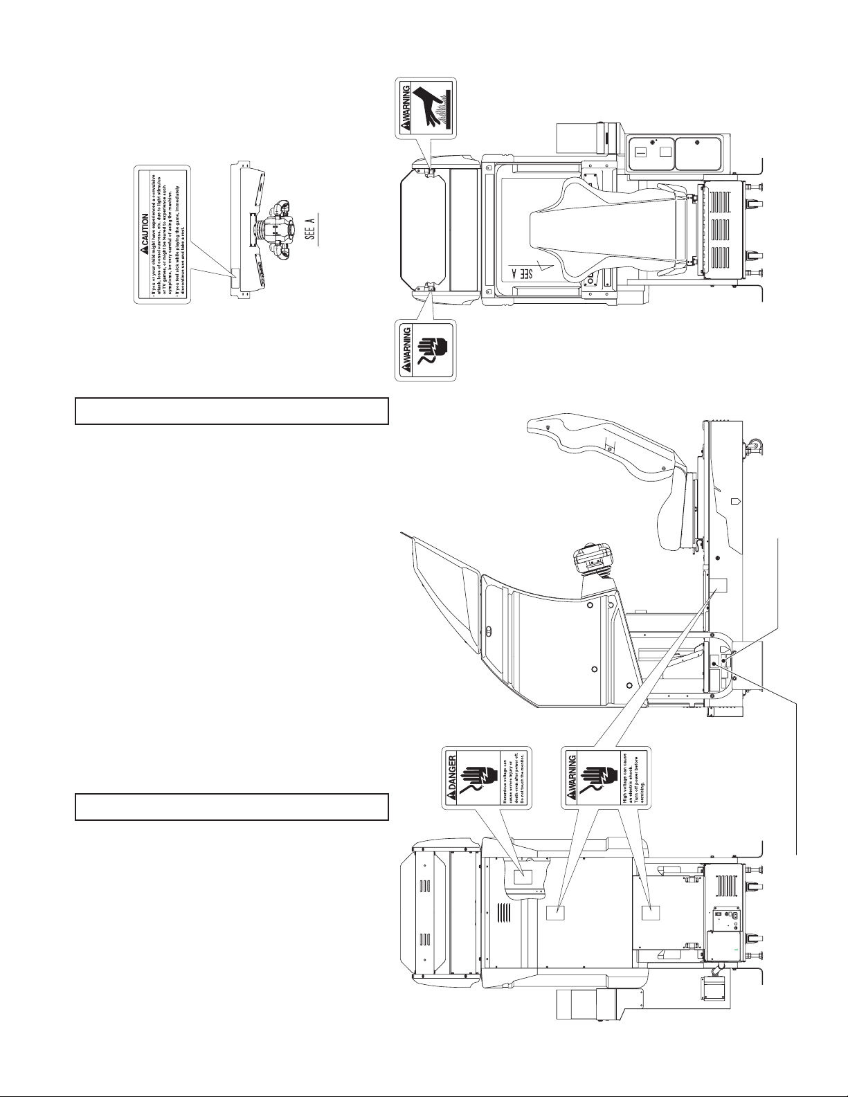
CONCERNING WARNING DISPLAYS
SEGA product has warning displays on Stickers,
Labels and or printed instructions adhered/attached
to or incorporated in the places where a potentially
hazardous situation can arise. The warning displays are
intended for accident prevention for the customers and
for avoiding hazardous situation relating to maintenance
and servicing work. There are some portions in the
Cabinet, which are subject to high tension voltage, etc.
where accidents can be caused merely by touching.
When performing the servicing work , be very careful
of the warning displays. Especially, any complex repair
and replacement work not mentioned herein, should
be performed by those technical personnel who have
knowledge of electricity and technical expertise.
For the prevention of accidents, caution any customer
whose act runs counter to the warnings, as to the effect
that he must stop the act.
CONCERNING THE STICKER DISPLAY
SEGA product has Stickers describing the product
manufacture No. (Serial No.) and Electrical
Specications. Also it has a Sticker describing where to
contact for repair and for purchasing parts.
When inquiring about or asking for repair, mention
the Serial No. and Name of Machine indicated on the
Sticker. The Serial No. indicates the product register.
Identical machines could have different parts depending
on the date of production. Also, improvements
and modications might have been made after the
publication of this Manual. In order to meet the above
situations, mention the Serial No. when contacting the
applicable places.
1
www.seuservice.com
Page 10
3
www.seuservice.com
1. HANDLING PRECAUTIONS
When installing or inspecting the machine, be very careful of the following points and pay attention to
ensure that the player can enjoy the game safely.
Non-compliance with the following points or inappropriate handling running counter to the cautionary
matters herein stated can cause personal injury or damage to the machine.
Before performing work, be sure to turn power off. Performing the work without
turning power off can cause an electric shock or short circuit. In the case work
WARNING!
should be performed in the status of power on, this manual always states to that
effect.
To avoid electric shock or short circuit, do not plug in or unplug quickly.
To avoid electric shock, do not plug in or unplug with a wet hand.
Do not expose Power Cords and Earth Wires on the surface, (oor, passage, etc.).
If exposed, the Power Cords and Earth Wires are susceptible to damage. Damaged
cords and wires can cause electric shock or short circuit.
To avoid causing a re or electric shock, do not put things on or damage Power
Cords.
When or after installing the product, do not unnecessarily pull the power cord. If
damaged, the power cord can cause a re or electric shock.
In case the power cord is damaged, ask for replacement through where the product
was purchased from or the ofce herein stated. Using the cord as is damaged can
cause re, electric shock or leakage.
Be sure to perform grounding appropriately. Inappropriate grounding can cause an
electric shock.
Be sure to use fuses meeting specied rating. Using fuses exceeding the specied
rating can cause a re or electric shock.
Completely make connector connections for IC BD and others. Insufcient insertion
can cause an electric shock.
Specication changes, removal of equipment, conversion and/or addition, not
designated by SEGA are not permitted.
• Failure to observe this may cause a re or an electric shock. Non-compliance with
this instruction can have a bad inuence upon physical conditions of the players or
the lookers-on, or result in injury during play.
• SEGA shall not be held responsible for damage, compensation for damage to a third
party, caused by specication changes not designated by SEGA.
Be sure to perform periodic maintenance inspections herein stated.
www.seuservice.com
2
Page 11
STOP
IMPORTANT!
For the IC board circuit inspections, only the logic tester is allowed. The use of a
multiple-purpose tester is not permitted, so be careful in this regard.
The Projector is employed for this machine. The Projector's screen is susceptible
to damage, therefore, be very careful when cleaning the screen. For details, refer to
PROJECTOR.
Static electricity from your body may damage some electronics devices on the IC
board. Before handling the IC board, touch a grounded metallic surface so that the
static electricity can be discharged.
Some parts are the ones designed and manufactured not specically for this game
machine. The manufacturers may discontinue, or change the specications of, such
general-purpose parts. If this is the case, Sega cannot repair or replace a failed game
machine whether or not a warranty period has expired.
3
www.seuservice.com
Page 12
5
www.seuservice.com
2.
PRECAUTIONS REGARDING INSTALLATION LOCATION
This product is an indoor game machine. Do not install it outside. Even indoors, avoid
installing in places mentioned below so as not to cause a re, electric shock, injury and
WARNING!
LIMITATIONS OF USAGE REQUIREMENTS
or malfunctioning.
Places subject to rain or water leakage, or places subject to high humidity in the
proximity of an indoor swimming pool and or shower, etc.
Places subject to direct sunlight, or places subject to high temperatures in the
proximity of heating units, etc.
Places lled with inammable gas or vicinity of highly inammable/volatile
chemicals or hazardous matter.
Dusty places.
Sloped surfaces.
Places subject to any type of violent impact.
Vicinity of anti-disaster facilities such as re exits and re extinguishers.
The operating (ambient) temperature range is from 5˚ to 30˚.
Be sure to check the Electrical Specications.
Ensure that this product is compatible with the location's power supply, voltage and
WARNING!
A plate describing Electrical Specications is attached to the product.
Non-compliance with the Electrical Specications can cause a re and electric
This product requires the Breaker and Earth Mechanisms as part of the location
Ensure that the indoor wiring for the power supply is rated at 7 A or higher (AC
Be sure to independently use the power supply equipped with the Earth Leakage
Putting many loads on one electrical outlet can cause generation of heat and a re
When using an extension cord, ensure that the cord is rated at 7 A or higher (AC
frequency requirements.
shock.
facilities. Using them in a manner not independent can cause a re and electric
shock.
single phase 100~120 V area), and 4 A or higher (AC 220~240 V area). Noncompliance with the Electrical Specications can cause a re and electric shock.
Breaker. Using a power supply without the Earth Leakage Breaker can cause an
outbreak of re when earth leakage occurs.
resulting from overload.
100~120 V area) and 4 A or higher (AC 220~240 V area). Using a cord rated lower
than the specied rating can cause a re and electric shock.
www.seuservice.com
4
Page 13

OPERATION AREA
For the operation of this machine, secure a minimum area of 6 Ft (W) × 7.5 Ft (D).
WARNING!
Be sure to provide sufcient space so as to allow this product's ventilation fan to
SEGA shall not be held responsible for damage, compensation for damage to a third
In order to prevent injury resulting from the falling down accident during game
play, be sure to secure the minimum area for operation.
function efciently. To avoid machine malfunctioning and a re, do not place any
obstacles near the ventilation opening.
party, resulting from the failure to observe this instruction.
STOP
For transporting the machine into the location's building, the minimum necessary
dimensions of the opening (of doors, etc.) are 40 in (W) and 77 in (H).
IMPORTANT!
Electric current consumption
MAX. 5 A (AC 120 V 60 Hz)
FIG. 2
5
www.seuservice.com
Page 14
7
www.seuservice.com
3. PRECAUTION REGARDING PRODUCT OPERATION
PRECAUTIONS TO BE HEEDED BEFORE STARTING THE OPERATION
To avoid injury and trouble, be sure to constantly give careful attention to the behavior and manner of the
visitors and players.
In order to avoid accidents, check the following before starting the operation:
To ensure maximum safety for the players and the customers, ensure that where
WARNING!
the product is operated has sufcient lighting to allow any warnings to be read.
Operation under insufcient lighting can cause bodily contact with each other, hitting
accident, and or trouble between customers.
Be sure to perform appropriate adjustment of the monitor (projector). For operation
of this machine, do not leave monitor's ickering or deviation as is. Failure to
observe this can have a bad inuence upon the players' or the customers' physical
conditions.
It is suggested to ensure a space allowing the players who feel sick while playing the
game to take a rest.
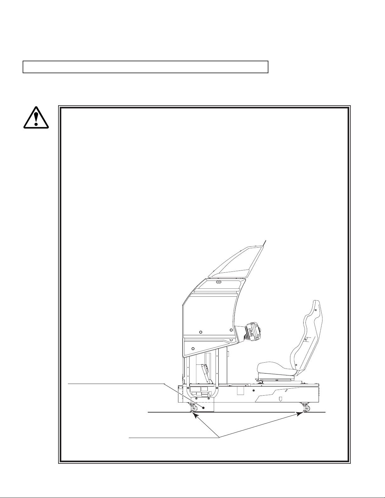
Check if all of the adjusters are in contact with the surface. If they are not, the
Cabinet can move and cause an accident.
Ensure that all of the
SUPPORT BRACKET are in contact
with the oor.
www.seuservice.com
Ensure that all of the
Adjusters are in contact
with the oor.
6
Page 15

Do not put any heavy item on this product. Placing any heavy item on the product
WARNING!
Do not climb on the product. Climbing on the product can cause falling down
To avoid electric shock, check to see if door & cover parts are damaged or omitted.
To avoid electric shock, short circuit and or parts damage, do not put the following
Flower vases, owerpots, cups, water tanks, cosmetics, and receptacles/containers/
To avoid injury, be sure to provide sufcient space by considering the potentially
CAUTION!
Check the control devices to make sure that there are no scratches or cracks on parts
can cause a falling down accident or parts damage.
accidents. To check the top portion of the product, use a step.
items on or in the periphery of the product.
vessels containing chemicals and water.
crowded situation at the installation location. Insufcient installation space can
cause making bodily contact with each other, hitting accidents, and or trouble
between customers.
touched by players, as such defects can cause injury to hands and ngers.
STOP
IMPORTANT!
This product features a license card slot and a memory card slot. Check to make sure that
these parts have not been tampered with (e.g. by inserting foreign objects.)
7
www.seuservice.com
Page 16
9
www.seuservice.com
DURING OPERATION(PATRON CONDUCT)
To avoid injury and trouble, be sure to constantly give careful attention to the behavior and
manner of the visitors and players.
To avoid injury and accidents, those who fall under the following categories are not
allowed to play the game.
WARNING!
• Those who need assistance such as the use of an apparatus when walking.
• Those who have high blood pressure or a heart problem.
• Those who have experienced muscle convulsion or loss of consciousness when playing
video game, etc.
• Those who have a trouble in the neck and or spinal cord.
• Intoxicated persons.
• Pregnant women or those who are in the likelihood of pregnancy.
• Persons susceptible to motion sickness.
• Persons whose act runs counter to the product's warning displays.
A player who has never been adversely affected by light stimulus might experience
dizziness or headache depending on his physical condition when playing the game.
Especially, small children can be subject to those conditions. Caution guardians of
small children to keep watch on their children during play.
Instruct those who feel sick during play to have a medical examination.
To avoid injury resulting from falling down and electric shock due to spilled drinks,
instruct the player not to place heavy items or drinks on the product.
To avoid electric shock and short circuit, do not allow patrons to put hands and
ngers or extraneous matter in the openings of the product or small openings in or
around the doors.
To avoid falling down and injury resulting from falling down, immediately stop the
patron's leaning against or climbing on the product, etc.
To avoid electric shock and short circuit, do not allow the patrons to unplug the
power plug without a justiable reason.
This product is intended for 1 Player only. Playing the game by 2 or more Players
riding on the seat together can cause falling down and collision accidents by striking
head, hand, or elbow.
Persons other than the player should not be allowed to touch the controls during play.
They may brush against or collide with the controls or the player, possibly resulting
in accidents.
www.seuservice.com
8
Page 17
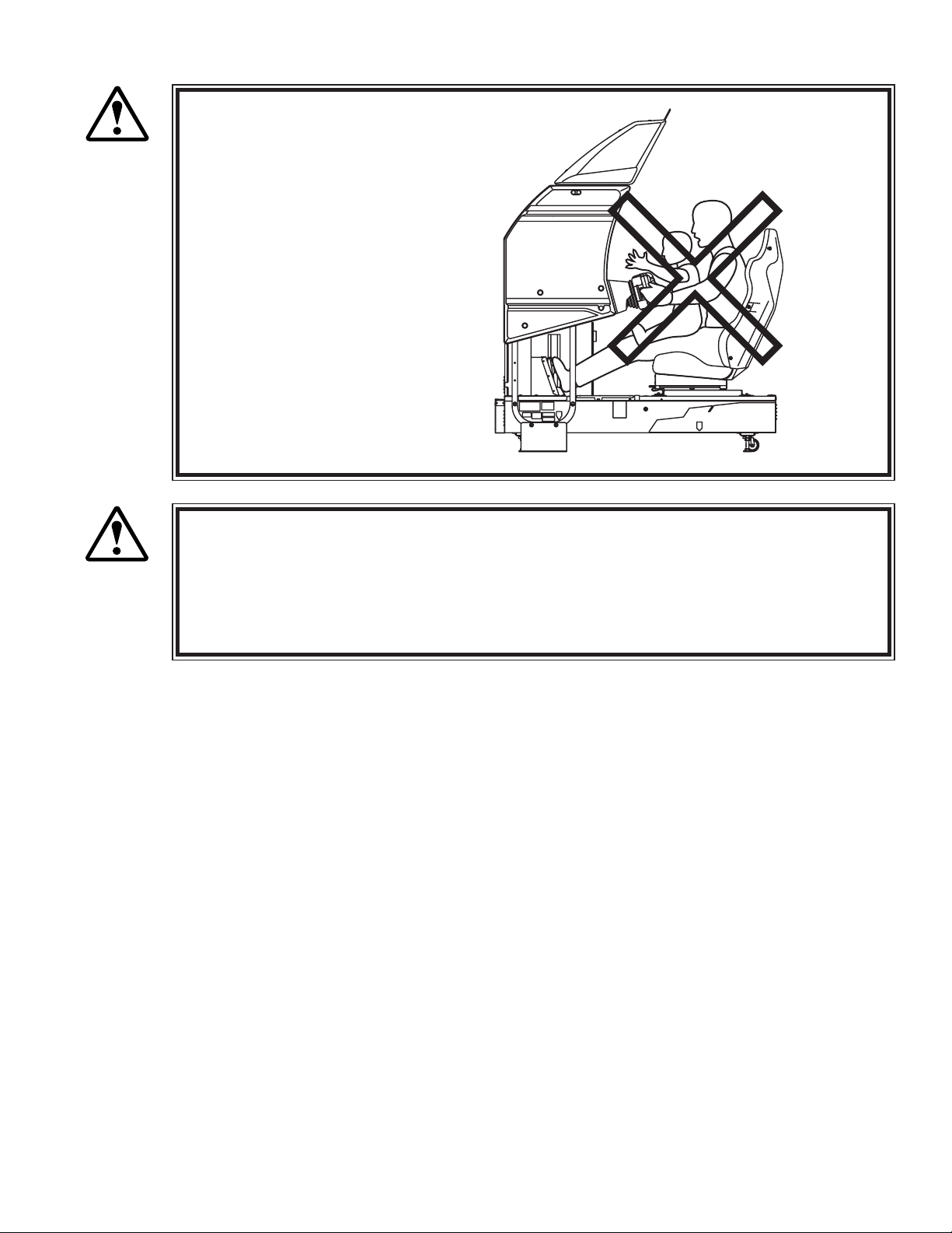
Caution the player so as not to
WARNING!
Immediately stop such violent acts as hitting and kicking the product. Such violent
CAUTION!
Instruct the Player to adjust the seat before playing the game. Playing the game in a
hold a child in her/his lap to
play. Failure to observe this
may cause the child to be
caught between the Control
Panel and the player and fall
down.
acts can cause parts damage or falling down, resulting in injury due to fragments and
falling down.
forcible posture can cause a contingent accident.
9
www.seuservice.com
Page 18
11
www.seuservice.com
OPERATING THE CARD SYSTEM
STOP
IMPORTANT!
If the card reader/writer has not been set as being unused, you will be unable to select any game mode
with use of cards while the game will be in progress.
Thus, for the card reader/writer, deal with the player, paying attention to the following points:
Even if the player request the system for use of cards when you have set the machine so that the card
reader/writer is not used, the request is rejected because of the nature of the system.
When an unjust act is performed, no written data is backed up mechanically.
The following acts may be judged to be unjust acts.
Since it also becomes a defect of operation and the cause of parts damage, caution
the player not to perform the following acts.
•Use of cards bent or deformed
•Use of cards adhered seals or extraneous matter on
•Use of a card mixed two sheets
•Use of cards other than dedicated cards
•When a card is extracted quickly
Since the order in which cards are dispensed is random, note that there may be cases
in which the same card comes out several times in a row or a certain card fails to
come out at all.
www.seuservice.com
10
Page 19
F
-z
e
ro
LIC
E
N
C
E
C
A
R
D
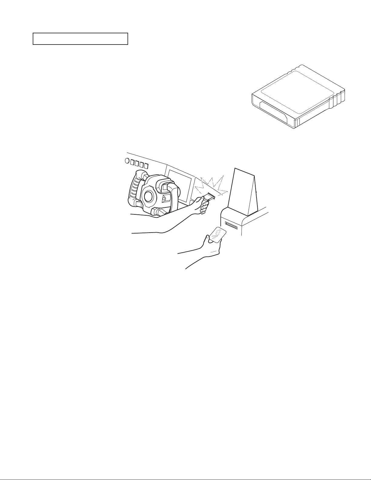
USING MEMORY CARDS
Players who use memory cards should be advised of the following
precautions. Data that is damaged or lost cannot be recovered.
- Before inserting a memory card, check to make sure there are no
problems with the slot.
- When using a memory card and a license card at the same time,
insert the memory card rst. Player data will not be used in the
game if the cards are inserted in the wrong order.
- Be sure to use a memory card containing "F-ZERO GX" game data.
- Never attempt to remove/insert a card during play. Doing so may damage the data.
- Do not use memory cards other than authorized Nintendo products or ofcial licensed products.
11
www.seuservice.com
Page 20
13
www.seuservice.com
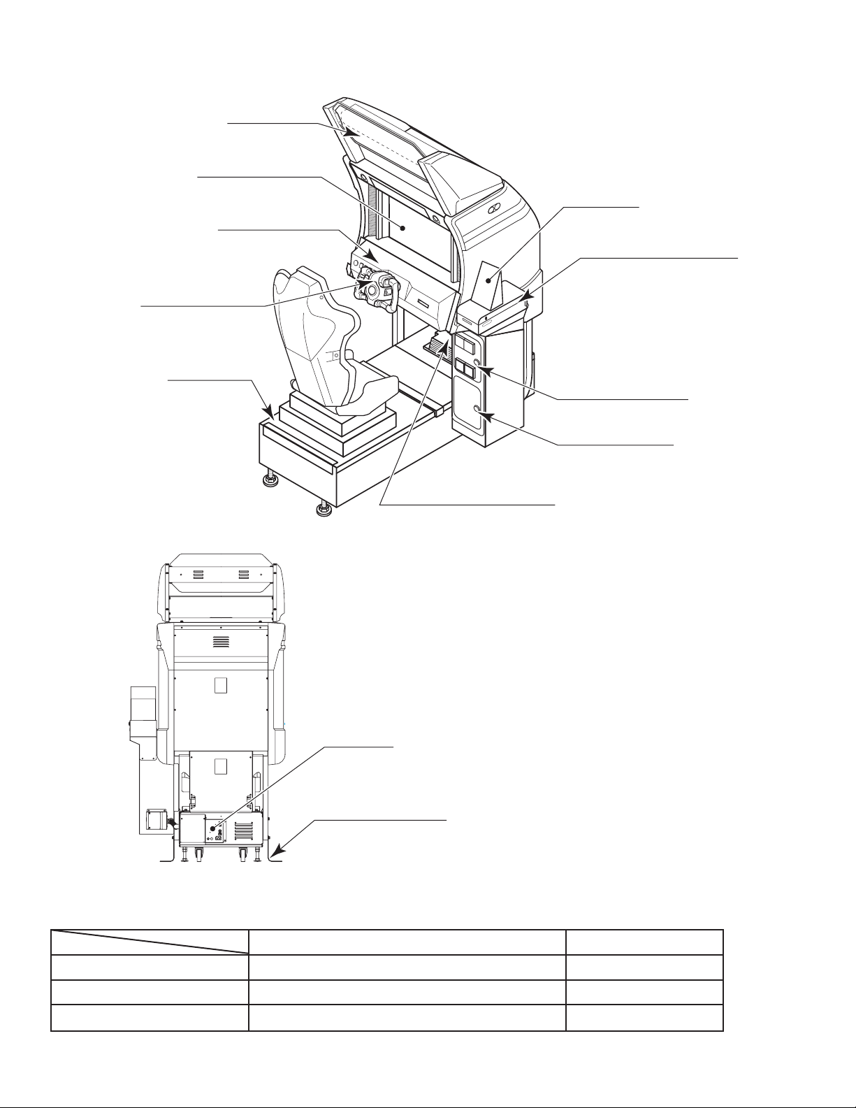
BILLBOARD
29 TYPE MONITER
MAIN BASE
CASHBOX DOOR
COIN CHUTE DOOR
AC UNIT
CONTROL PANEL
ACCELERATOR & BRAKE
CARD READER/WRITER
POP CARD
SUPPORT BRACKET
STEERIN G WHEEL
4. NAMES OF PARTS
FIG. 4 a OVERVIEW
FIG. 4 b REAR VIEW
TABLE 4 Dimensions and Weights
Width × Length × Height Weight
CABINET 39 in × 68.5 in × 60 in 550 lbs
BILLBOARD 32 in × 26 in × 17 in 28.6 lbs
When assembled 39 in × 68.5 in × 77 in 580 lbs
www.seuservice.com
12
Page 21
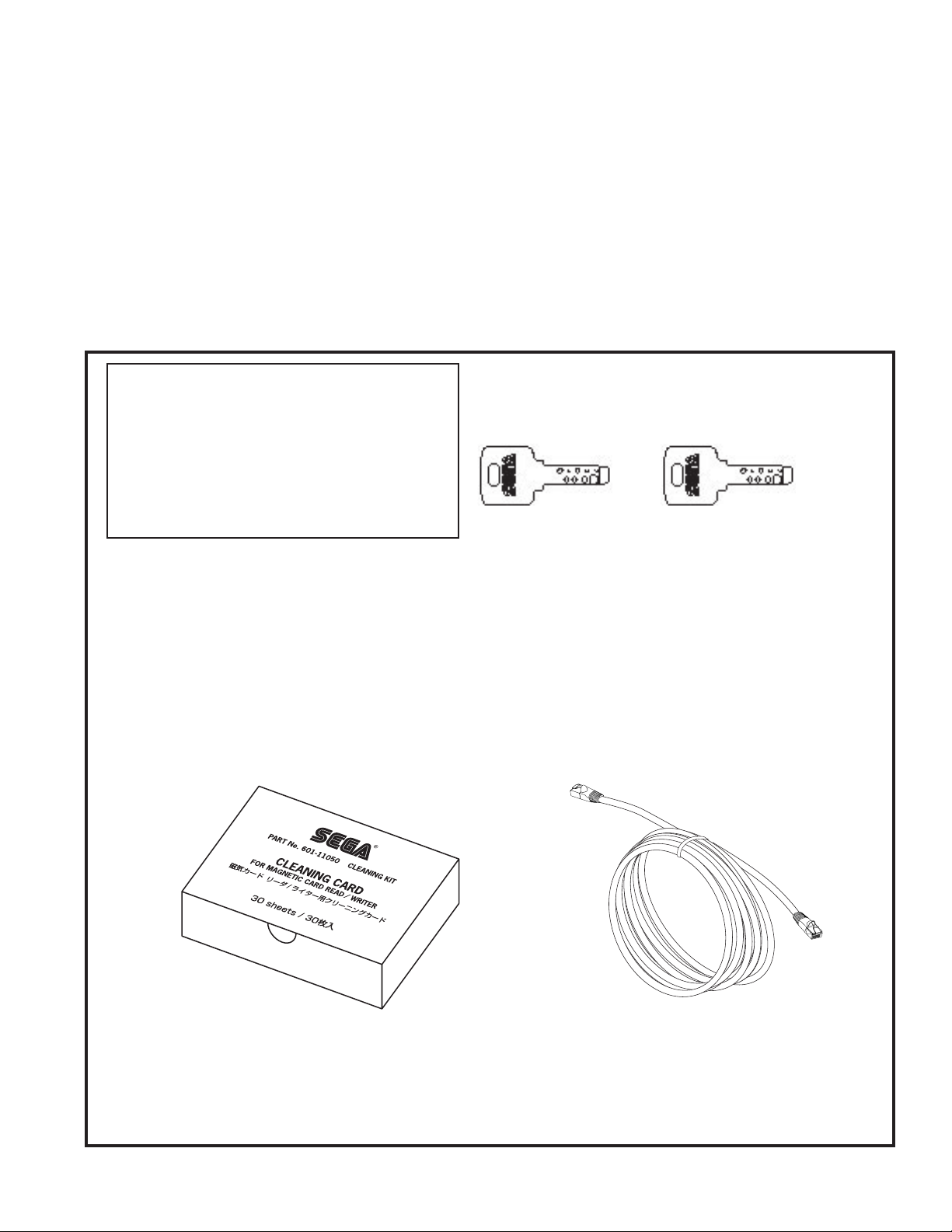
5. ACCESSORIES
When transporting the machine, make sure that the following parts are supplied.
Magnetic cards for the recording of play results, and cleaning kits for cleaning the head of the card reader/
writer are sold separately. Subsequent purchases of these items can be made by contacting the ofce listed
on this Owner's Manual or the dealer from whom the product was originally purchased. Be sure to provide
the part number(s), name(s), and required number of items.
Cleaning Kit
601-11050 CLEANING CARD: Package of 30 sheets
Magnetic Cards
601-11334-01 CARD PACKAGE FZR ENG: Package of 200 Magnetic Cards
TABLE 5 a ACCESSORIES
DESCRIPTION OWNER'S MANUAL
Part No. (Qty.) 999-1930
Notes
Figures
Parts not labeled with part numbers are as yet
unregistered or cannot be registered. Be sure to
handle all parts with care, as some parts are not
available for purchase separately.
CLEANING CARD
601-11050 (1)
For the periodic maintenance. See Sections 7 and 10.
(30 sheets of Cleaning Card)
KEY MASTER
220-5576 (2)
For opening/closing
the doors
ASSY FIBER CABLE (NETWORK CABLE) 5 m
600-7269-0500 (1)
Used for the Network Play. See Section 20.
KEY
(2)
For the CASHBOX DOOR
The Keys are inside the Coin
Chute Door at the time of shipment from the factory.
13
www.seuservice.com
Page 22
15
www.seuservice.com
GD SOFT KIT FZR
610-0650-0004 (1) <OTHERS>
GD-ROM software.
See 3 of Section 6.
CUSHION SPONGE
601-11137 (1)
GD-ROM Disc Protector
GD-ROM DISC
DISC CASE
253-5507
The following Table 5b lists the parts that are separately marketed but are necessary when booting this
product's software. When having unpacked the shipping crate, make sure that all the parts in this Table 5b
are in the crate. If not so, contact where you have obtained the product.
TABLE 5 b (XKT-0833 : GD-ROM DRIVE KIT)
GD-ROM DRIVE
610-0617
610-0617-01
Device that loads the software in a GD-ROM disc.
see 3 of Section 6.
(1)
123
GD-ROM DRIVE CARTON BOX (1)
Used for transporting the GD-ROM DRIVE.
See Section 19.
This carton box is a standard accessory of
the GD-ROM drive. If you want to obtain the
carton box itself separately, specify the part
number 601-11031.
www.seuservice.com
14
Page 23
6. ASSEMBLY AND INSTALLATION
Perform assembly work by following the procedure herein stated. Failing to comply
with the instructions can cause electric shock hazard.
WARNING!
Perform assembling as per this manual. Since this is a complex machine, erroneous
assembling can cause an electric shock, machine damage and or not functioning as
per specied performance.
When assembling, be sure to use plural persons. Depending on the assembly work,
there are some cases in which working by one person alone can cause personal
injury or parts damage.
Ensure that connectors are accurately connected. Incomplete connections can cause
electric shock hazard.
Be careful not to damage the wires. Damaged wires may cause electric shock or
short circuit or present a re risk.
This work should be performed by the site maintenance individual or other skilled
professional. Performing work by non-technical personnel can cause a severe
accident such as electric shock. Failing to comply with this instruction can cause a
severe accident such as electric shock to the player during operation.
Provide sufcient space so that assembling can be performed. Performing work in
places with narrow space or low ceiling may cause an accident and assembly work
to be difcult.
To perform work safely and avoid serious accident such as the cabinet's falling
down, do not perform work in places where step-like grade differences, a ditch, or
slope exist.
Do not leave power cords, grounding wires, or network cables exposed in areas of
heavy foot trafc. Doing so may cause them to become damaged, possibly resulting
in electric shock and/or short circuits. When laying wiring across the oor, always
use safety covers to protect the wires. (Wiring diameter: power cable - approx. 8mm;
network cable - approx. 5mm)
CAUTION!
Handle molded parts with care. Undue weight or pressure may cause them to break
and the broken pieces may cause injury.
To perform work safely and securely, be sure to prepare a step which is in a secure
and stable condition. Performing work without using the step can cause violent
falling down accidents.
Make sure that the GD cable connector is inserted parallel to the plug. Improper
insertion may cause damage to the connector and present a re risk.
15
www.seuservice.com
Page 24
17
www.seuservice.com
When carrying out the assembling and installation, follow the following 6-item sequence.
INSTALLING THE BILLBOARD AND THE POP CARD
1
SECURING IN PLACE(ADJUSTER ADJUSTMENT)
2
INSTALLING THE GD-ROM DRIVE(SETTING THE GD-ROM DISC)
3
POWER SUPPLY, AND EARTH CONNECTION
4
TURNING THE POWER ON
5
ASSEMBLY CHECK
6
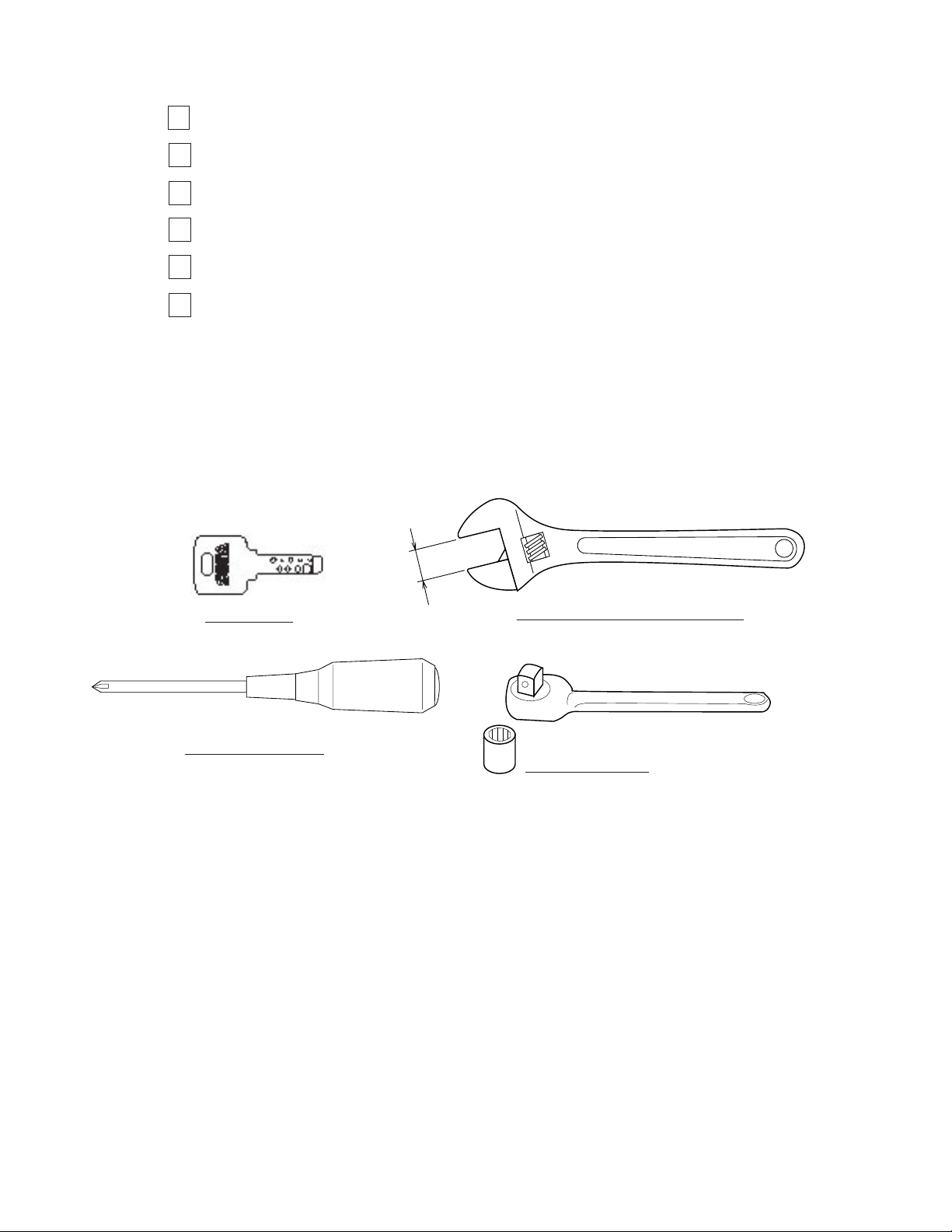
The master key (accessories) in addition to the tools such as a Phillips type screwdriver, wrench,
socket wrench and Ratchet Handle are required for the assembly work.
KEY MASTER
Phillips type screwdriver
24mm
WRENCH (for M16 hexagon-head bolt)
SOCKET WRENCH,(for M8 hexagon-head bolt)
RATCHET HANDLE
www.seuservice.com
16
Page 25
1
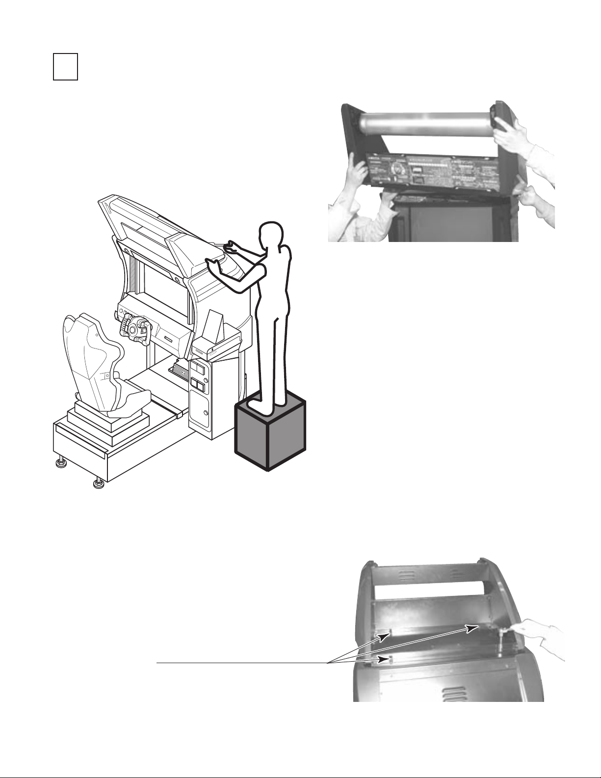
INSTALLING THE BILLBOARD AND POP CARD
Install the billboard on the
cabinet. This operation should be
performed by at least 2 people
working together.
PHOTO 6. 1 a
FIG. 6. 1 a
Secure the billboard with 4 hexagonal
bolts.
HEXAGONAL BOLT(4), black
M8×20, w/spring washer, at washer used
For performing work, prepare a step.
PHOTO 6. 1 b
17
www.seuservice.com
Page 26
19
www.seuservice.com
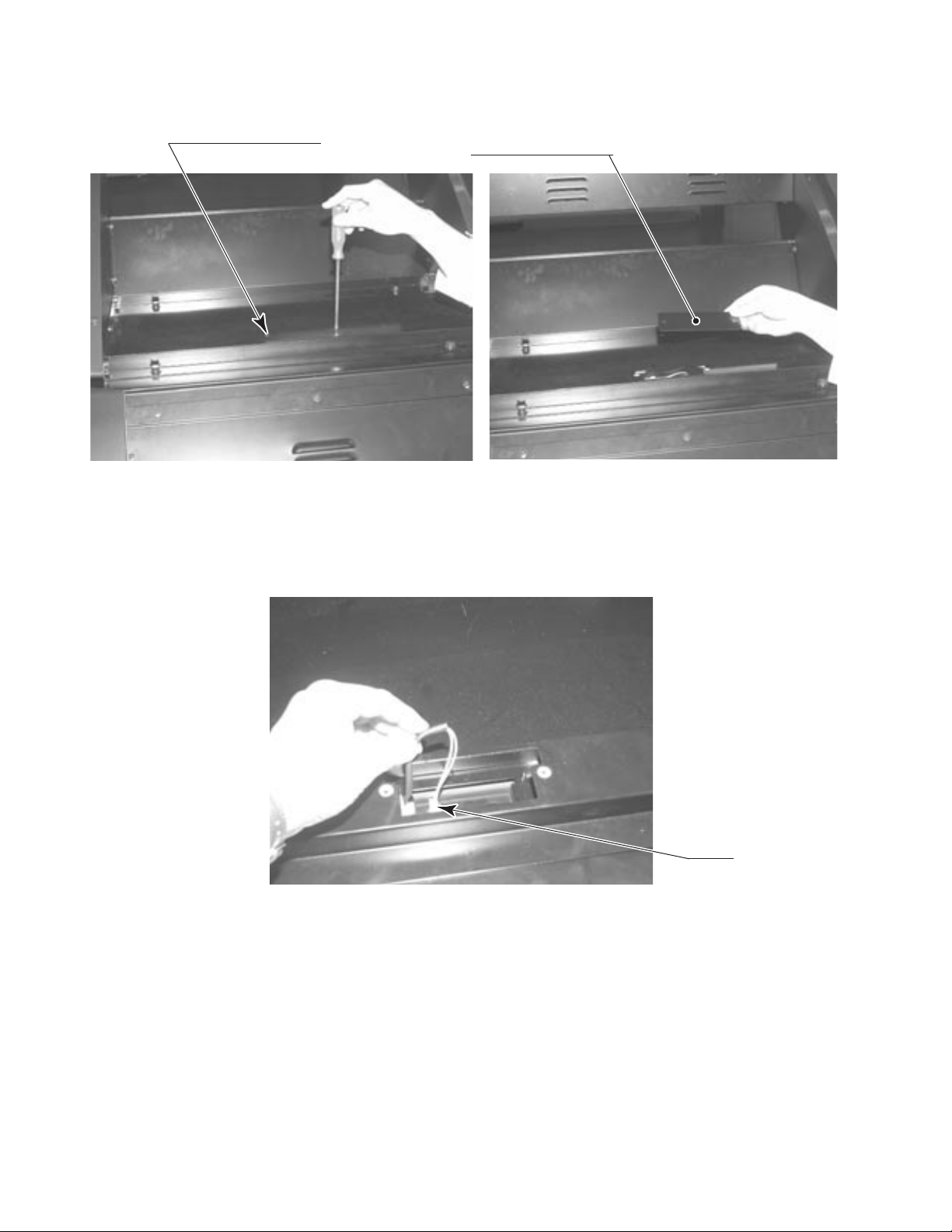
Remove the 2 truss screws from the connector lid and then remove the lid.
TRUSS SCREW (2), black
M4×8
Plug in the connectors.
CONNECTOR LID
PHOTO 6. 1 c
Re-install the 2 truss screws on the connector lid.
www.seuservice.com
PHOTO 6. 1 d
18
Connect
Page 27
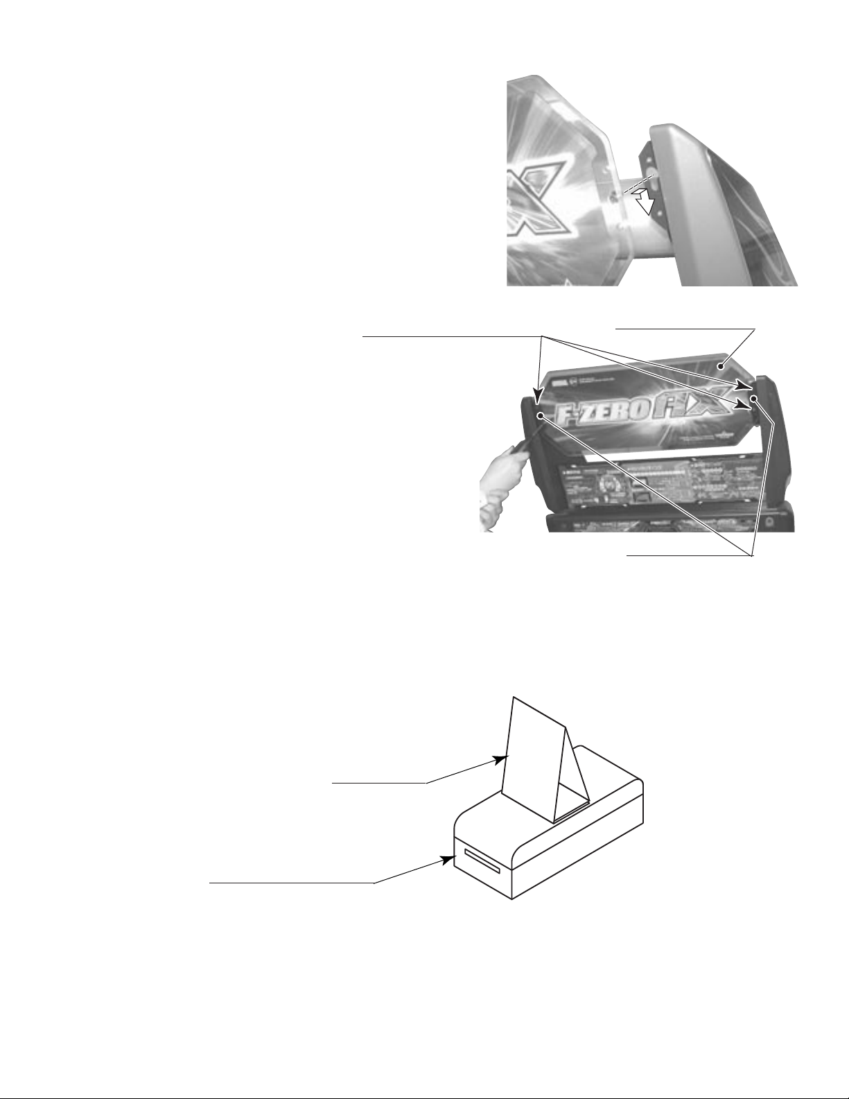
Attach the billboard plate to the billboard.
Secure each side of the billboard with 2 truss
screws and a plate sash.
TRUSS SCREW (2 ea.) black
M5×12
BILLBOARD PLATE
PLATE SASH
PHOTO 6. 1 e
Assembling the POP Card as shown in the gure and attach it to the top of the Card Reader/Writer.
POP CARD
CARD READER/WRITER
19
FIG. 6. 1
www.seuservice.com
Page 28
21
www.seuservice.com
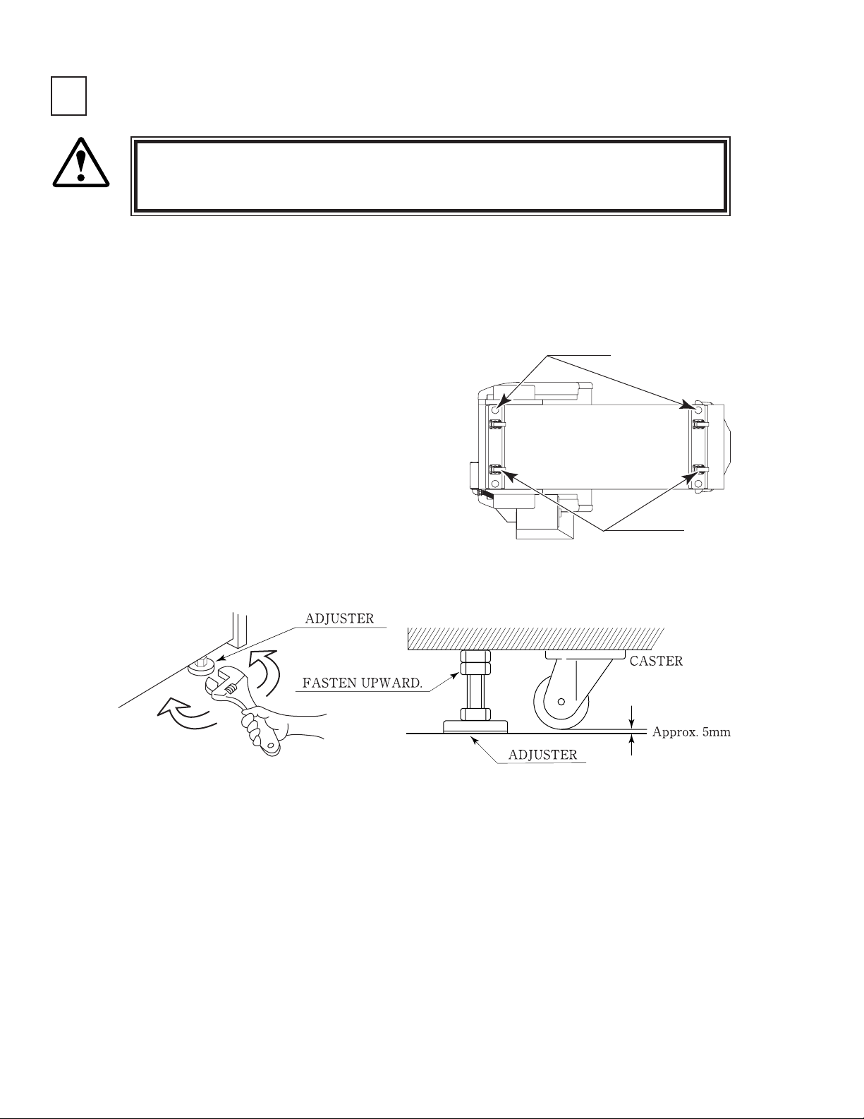
2
SECURING IN PLACE (ADJUSTER ADJUSTMENT)
Make sure that all of the adjusters are in contact with the oor. If they are not, the
cabinet can move and cause an accident.
WARNING!
This product has 4 casters and 4 Adjusters. (FIG. 6. 2 a) When the installation position is
determined, cause the adjusters to come into contact with the oor directly, make adjustments
in a manner so that the casters will be raised approximately 5 mm from the oor and make sure
that the machine position is level.
Transport the product to the installation position.
Have all of the Adjusters make contact with the
oor. Adjust the Adjuster's height by using a
wrench so that the machine position is kept level.
After making adjustment, fasten the Adjuster Nut
upward and secure the height of Adjuster.
ADJUSTER
CASTER
FIG. 6. 2 a BOTTOM VIEW
www.seuservice.com
FIG. 6. 2 b ADJUSTER
20
Page 29
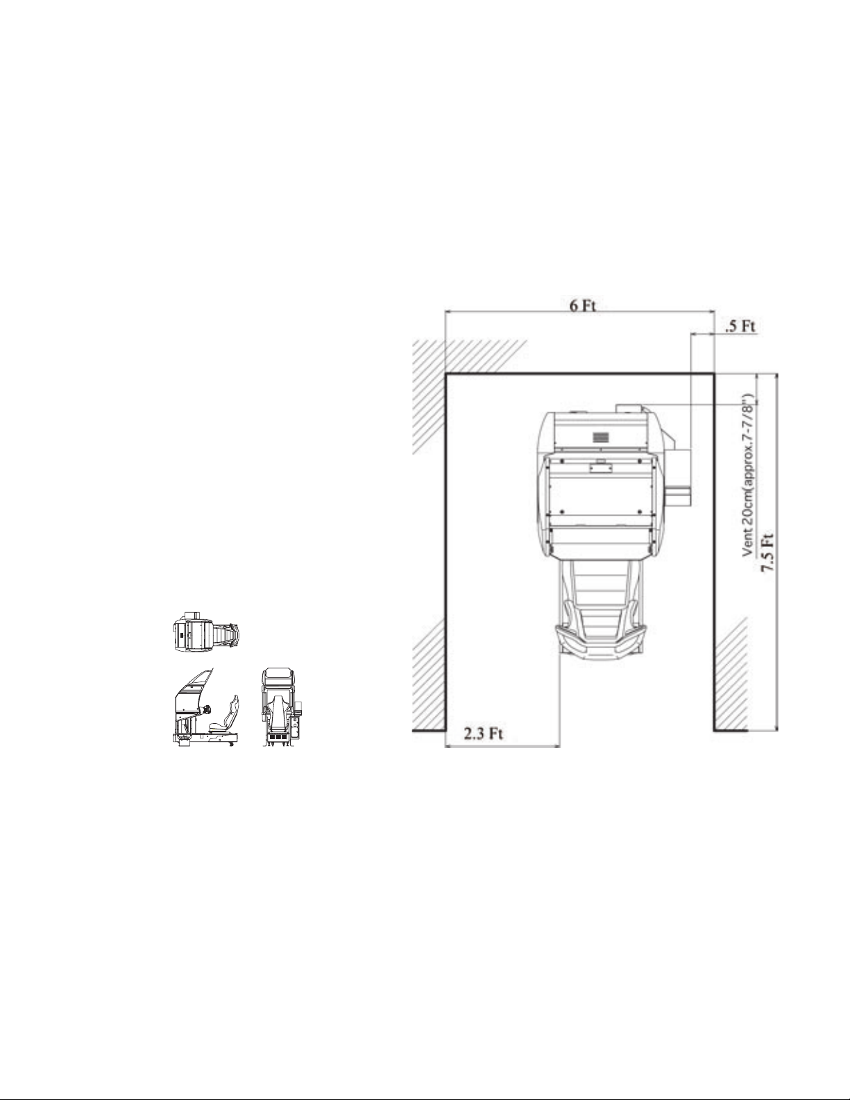
FIG. 6. 2 d
Refer to this Fig. (Scale:1/100)
for the layout of the place of
installation.
FIG. 6. 2 e
Provide ventilation space for the ventilation opening.
Allow more than 70 cm (approx. 28 in) of space for
customer trafc.
21
www.seuservice.com
Page 30
23
www.seuservice.com
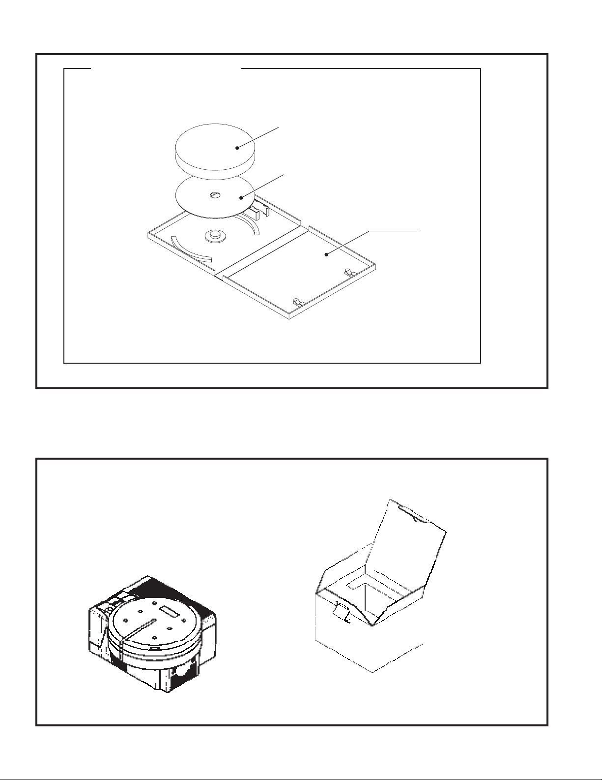
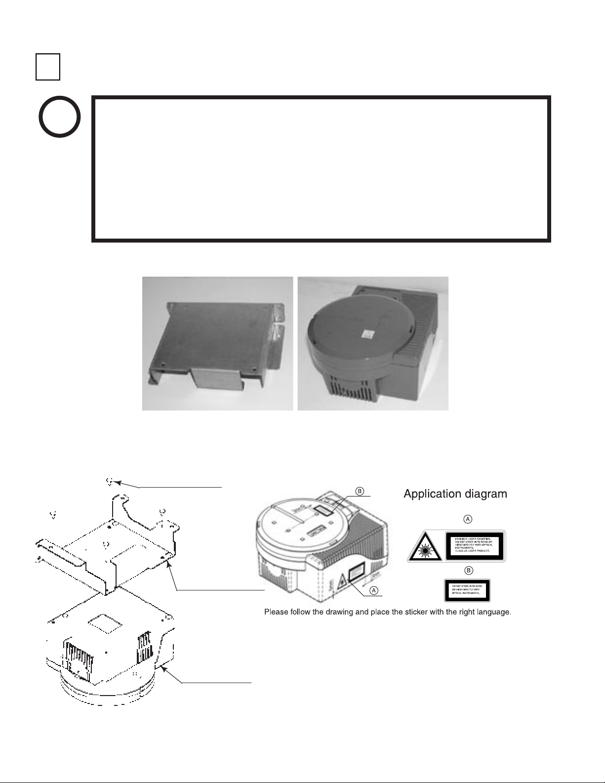
INSTALLING THE GD-ROM DRIVE (SETTING THE GD-ROM DISC)
3
STOP
IMPORTANT!
Unpack the shipping crate, and take out the GD-ROM drive, GD-ROM drive bracket, and GD-ROM
disc.
Carefully handle the GD-ROM drive so as not to contaminate the disc and the
readout lens with stains and dust particles.
Do not continue to use the scratched GD-ROM disc. The scratched GD-ROM disc
may cause the system to malfunction.
Set the GD-ROM disc onto the GD-ROM drive with its labeled side facing upward.
The key chip is a precision device. Handle it carefully and avoid exposure to heat,
shock and static electricity, as these may cause damage to the device.
The key chip is contained in the GD-ROM disc case. Always use them as a set.
GD DRIVE BRACKET GD-ROM DRIVE
PHOTO 6. 3 a
Use the 4 tapping screws to x the GD-ROM drive bracket onto the GD-ROM drive. Be careful about a
xing direction.
TAPPING SCREW (4)
M4×8
GD DRIVE BRACKET
FIG. 6. 3 b
CAUTION for U. S. A., Europe, and Australia:
GD-ROM DRIVE
Attach the 2 caution stickers for a laser ray onto
the GD-ROM drive.
FIG. 6. 3 a
www.seuservice.com
22
Page 31

Remove the 1 truss screw that xes the GD-ROM
drive lid (DISC LID). And turn clockwise the lid
to remove. Keep the screw to replace the disc lid
below.
TRUSS SCREW (1)
M3×8
PHOTO 6. 3 b
Set the GD-ROM disc onto the GD-ROM drive with its labeled side facing upward.
Return the lid to its original place, and x it with 1 truss screw. Be careful not to fasten the screw too
tightly.
PHOTO 6. 3 c
TRUSS SCREW (1)
M3×8
23
www.seuservice.com
Page 32

25
www.seuservice.com
Undo the lock on the side of the unit base and remove the Truss screws.
Turn the lock handle to open the lock, and lower the seat towards the backrest. Slowly lower the backrest
until it touches the oor to prevent damage to the seat components. Put a drop cloth on the oor to
prevent damaging the surface of the seat components.
LOCK HANDLE
Unlock.
DROP CLOTH TO PREVENT DAMAGE
TO SURFACE OF PARTS
TRUSS SCREW (2), black
M5×12
FIG. 6. 3 b
Attach the GD-ROM drive with 3 screws.
www.seuservice.com
PHOTO 6. 3 d
24
SCREW (3)
M4×16,
w/at & spring washers
Page 33

Connect the GD cable connector to TRIFORCE. Insert both the GD cable connector and the power cord
connector (JST NH6P) into the GD-ROM drive. Be careful about an inserting direction in this instance.
Make sure that the connectors are inserted rmly and completely. Secure the cable with the cord clamp.
GD CABLE CONNECTOR
Secure the cable.
POWER CORD CONNECTOR
JST NH6P
PHOTO 6. 3 e
TRIFORCE
GD CABLE CONNECTOR
25
www.seuservice.com
Page 34

27
www.seuservice.com
4
POWER SUPPLY, AND EARTH CONNECTION
Be sure to independently use the power supply socket outlet equipped with an Earth
WARNING!
Ensure that the "accurately grounded indoor earth terminal" and the earth wire
Ensure that the power cord and earth wire are not exposed on the surface (passage,
After wiring power cord on the oor, be sure to protect the power cord. Exposed
Leakage Breaker. Using a power supply without an Earth Leakage Breaker can
cause a re when electric leakage occurs.
cable are available (except in the case where a power cord plug with earth is used).
This product is equipped with the earth terminal. Connect the earth terminal and
the indoor earth terminal with the prepared cable. If the grounding work is not
performed appropriately, customers can be subjected to an electric shock, and the
product's functioning may not be stable.
etc.). If exposed, they can be caught and are susceptible to damage. If damaged,
the cord and wire can cause electric shock and short circuit accidents. Ensure that
the wiring position is not in the customer's passage way or the wiring has protective
covering.
power cord is susceptible to damage and causes an electric shock accident.
The AC Unit is located on one side of Cabinet. The AC Unit has Main SW, Earth Terminal and
the Inlet which connects the Power Cord.
Ensure that the Main SW is OFF.
MAIN SW
CIRCUIT PROTECTOR
Main SW off
AC Cable (Power Cord)
To the Power Supply
EARTH TERMINAL <For Taiwan>
Connect with the indoor earth terminal.
INLET
Socket outlet
www.seuservice.com
FIG. 6. 4 a AC UNIT
26
Page 35

Connect one end of the earth wire to
the AC Unit earth terminal, and the
other end to the indoor earth terminal.
The AC Unit earth terminal has a
Bolt and Nut combination. Take off
the Nut, pass the end of earth wire
through the Bolt, and fasten the Nut.
<For Taiwan>
*Note that the Earth Wire is
incorporated in the Power Cord for
the Areas of AC 120 V (USA) and
AC 220~240 V, and therefore, this
procedure is not necessary.
Firmly insert the power plug into the
socket outlet.
Insert the opposite side of Power
Cord plug to the AC Unit's connector
("INLET").
Connect the Earth Wire
to the Earth Terminal.
FIG. 6. 4 b *Earth Wire Connection
Perform wiring for the Power Cord
and Earth Wire. Install protective
covering for the Power Cord and
Earth Wire.
Wiring Cover
FIG. 6. 4 c Connecting Power Cord and Earth Wire
HOW TO USE THE CORD CLAMP
In case the Power Plug is apt to come out of place, secure the
Power Cord to the periphery of the AC Unit with the Cord
Clamp (an accessory).
27
www.seuservice.com
Page 36

29
www.seuservice.com
5
CAUTION!
TURNING THE POWER ON
Do not touch the machine until it has competed the initialization process and the
advertising screen has appeared. Doing so may cause the person touching the machine to
be struck by the seat. It may also prevent the machine from initializing properly. Failure
to initialize properly can lead to control malfunction and other problems.
Turn the main switch on the AC unit ON to turn on the power. The uorescent lamp inside the billboard
will light up when the power is turned on.
After displaying the system startup screen, the monitor will indicate that the card reader/writer and motor,
in that order, are being tested.
Next, the initialization screen will be displayed, and the initialization process will begin. Initialization
consists of the following steps, with each part moving and coming to rest in the preset position and
direction automatically.
1) The steering wheel rotates left and right.
2) The steering wheel comes to rest in a 12 o'clock position.
When the initialization process is complete, the machine will go into Advertising mode. The monitor will
display the demo screen, and the speakers to the left and right of the monitor and on the left and right of
the seat's headrest will begin sound output. If the "no sound during Advertising mode" option is selected,
sound output will be turned off.
When a sufcient number of credits have been inserted, the "Start" button on top of the control panel will
ash. After the race begins, the "View Change" button for the currently selected mode will light up. The
buttons will not be lit up during Advertising mode when no credits have been inserted.
After displaying the initialization screen, if the machine is set for network play, the monitor will indicate
that the network is being tested.
If there are no problems with the network play connection and settings, the machine will enter
Advertising mode.
If there is a problem with game board system, an error message will be displayed on the screen. If there
is a problem with steering unit response, an error message will be displayed. Refer to the on-screen error
message to locate and resolve the problem.
If, after the initialization process is complete, the seat comes to rest at an angle or the steering unit comes
to rest in a position other than straight, turn the power off and back on and have the machine go through
initialization again.
If the steering unit continues to come to rest at an angle after going through initialization again, there is
likely a problem such as bad VR settings or a glitch in the initialization process. Adjust the VR settings.
(See Sections 10, 11 and 12.)
If there are any defects or abnormalities in the network play connection or settings, the machine will
continue to display the network test screen. Check the network play cable connection and settings.
The machine will save the number of credits inserted and rankings data even when the power is turned
off. Fractions of credits (i.e. any coins inserted that do not add up to a full credit) and bonus adder count
data will not be saved.
www.seuservice.com
28
Page 37

FIG. 6. 5
29
www.seuservice.com
Page 38

31
www.seuservice.com
6
ASSEMBLY CHECK
In the TEST MODE, ascertain that the assembly has been made correctly and IC BD. is satisfactory
(refer to Section 10).
In the test mode, perform the following test:
(1)MEMORY TEST
Selecting RAM TEST or MEDIA BOARD
TEST from the menu screen in System Test
mode will cause the machine to automatically
perform a test of the memory on the game
boards. If "GOOD" is displayed next to the
number of each memory segment, the game
boards are working properly.
Select SYSTEM INFORMATION to display
information on the main game board and the
media board. If the information is displayed
correctly, this indicates that the game boards are
functioning properly.
���MEDIA�BOARD�TEST��1/2
����DOMM�BOARD(TYPE�3)
����VERSION��****
����STATUS���GOOD
����CHECKING�100%
����DIMM�TEST
����DIMM0�����-�GOOD
����DIMM1�����-�NONE
����GD-ROM����-�GOOD
��������RAM�TEST
����AUX�MEMORY����GOOD
PRESS�TEST�BUTTON�TO�EXIT
���MEDIA�BOARD�TEST��2/2
��NETWORK�BOARD
��VERSION��****
��STATUS���GOOD
��CHECKING�100%
��NETWORK�BOARD�TEST
��RAM�CHECK�_�GOOD
����--��COMPLETED��--
PRESS�TEST�BUTTON�TO�EXIT
����SYSTEM�INFORMATION
��MAIN�BOARD
����REGION���������****
����BOOT�VERSION���****
����FIRM�VERSION���****
����FPGA�VERSION���****
����SERIAL�NO.�***************
��MEDIA�BOARD
����DIMM�BOARD(TYPE�3)+�GDROM
����MEMORY�SIZE����512MB
����FIRM�VERSION���****
����SERIAL�NO.�***************
����NETWORK�BOARD
����FIRM�VERSION���*****
PRESS�TEST�BUTTON�TO�EXIT
www.seuservice.com
30
PRESS�TEST�BUTTON�TO�EXIT
Page 39

(2)INPUT TEST
Select INPUT TEST from the menu screen in either System Test mode or Game Test mode to
bring up a test screen for the input devices.
Test the input on each device. If "ON" is displayed next to each device as it is tested and the
numbers change smoothly in accordance with the input, the input devices and their wiring
connections are working properly.
��������������JVS�TEST
�������������INPUT�TEST
����NODE�������1/1
������SYSTEM�����00
������PLAYER�1���0000
������PLAYER�2���0000
������COIN�1�����0000
������COIN�2�����0000
������ANALOG�1���0000
������ANALOG�2���0000
������ANALOG�3���0000
������ANALOG�4���0000
������ANALOG�5���0000
������ANALOG�6���0000
������ANALOG�7���0000
������ANALOG�8���0000
PRESS�TEST�AND�SERVICE�BUTTON�TO�EXIT
�����������������������INPUT�TEST
STEERING��X�����0(~FF)�������SERVICE��������OFF(ON)
STEERING��Y�����0(~FF)�������TEST�����������OFF(ON)
PADDLE��LEFT����OFF(ON)
PADDLE��RIGHT���OFF(ON)
BOOST�����������OFF(ON)
GAS�������������0(~FF)
BRAKE�����������0(~FF)
START�BUTTON
VIEW�CHANGE�1���OFF(ON)
VIEW�CHANGE�2���OFF(ON)
VIEW�CHANGE�3���OFF(ON)
VIEW�CHANGE�4���OFF(ON)
�������PRESS�TEST�AND�SERVICE�BUTTON�TO�EXIT
31
www.seuservice.com
Page 40

33
www.seuservice.com
(3)SOUND TEST
��������SOUND�TEST
��OUTPUT�TYPE�������STEREO
��RIGHT�SPEAKER�����OFF
��LEFT��SPEAKER�����OFF
→EXIT
SELECT�WITH�SERVICE�BUTTON
��AND�PRESS�TEST�BUTTON
(4)C.R.T. TEST
�����������������C.R.T.�TEST�1/2
���������������������EDIT
�����1�������������→NEXT���������������32
RED
GREEN
BLUE
WHITE
����������SELECT�WITH�SERVICE�BUTTON
������������AND�PRESS�TEST�BUTTON
In the system test mode, selecting SOUND
TEST causes the screen (on which sound
related BD and wiring connections are
tested) to be displayed.
Check if the sound is satisfactorily emitted
from each speaker and the sound volume is
appropriate.
In the system test mode menu, selecting
C.R.T. TEST allows the screen (on which the
monitor is tested) to be displayed. Although
the monitor adjustments have been made
at the time of shipment from the factory,
color deviation, etc., may occur due to the
effect caused by geomagnetism, the location
building's steel frames and other game
machines in the periphery. By watching the
system test mode screen, make judgment as
to whether an adjustment is needed. If it is
necessary, adjust the monitor by referring to
Chapter 15.
C.R.T.�TEST�2/2
PRESS�TEST�BUTTON�TO�EXIT
www.seuservice.com
32
Page 41

(5)OUTPUT TEST
�����������OUTPUT�TEST�
���START�BUTTON������������OFF(ON)
���VIEW�CHANGE�1�����������OFF(ON)
���VIEW�CHANGE�2�����������OFF(ON)
���VIEW�CHANGE�3�����������OFF(ON)
���VIEW�CHANGE�4�����������OFF(ON)
���BOOST�������������������OFF(ON)
���STEERING
�����CENTER����������������OFF(ON)
�����LEFT������������������OFF(ON)
�����RIGHT�����������������OFF(ON)
->�EXIT�
���SELECT�WITH�SERVICE�BUTTON
�����AND�PRESS�TEST�BUTTON
Select OUTPUT TEST from the menu
screen in Game Test mode to bring up a test
screen for the output devices (lamps, etc.)
If each output device activates correctly, the
output devices and their wiring connections
are working properly.
Perform the above inspections also at the time of monthly inspection.
33
www.seuservice.com
Page 42

35
www.seuservice.com
7. CARD READER/WRITER
7-1 SETTING DEDICATED CARDS
STOP
IMPORTANT!
When the unit is out of cards, a message will be displayed at the center of the screen. Follow the
instructions below to restock the system with cards. Cards may be stocked when the unit is on or off.
Remove the truss screw.
Unlock and open the cover to nd the card reader/writer.
The dispenser on which you should place the cards is located at the rear of the reader/writer.
Be sure to use dedicated cards available for this product.
Use of ones other than such dedicated cards may cause a malfunction or failure of
the machine.
Be sure to set the specied number of card in the specied orientation by using the
specied procedure. Wrong setting of the cards may cause the machine to fail.
This machine allows you to set up to 100 cards at a time. You must not set over 101
cards at a time. If you do so, a trouble such as card jamming may occur.
Set virgin cards taken out from a container that was unpacked immediately before
use.
Use of any deformed or deteriorated card may cause a trouble.
Do not include a corrugated, bent, or used card in the card deck.
From the card reader/writer, take out the dispenser upward in a straight line.
Unlock.
www.seuservice.com
TRUSS SCREW(1), black
M4×8
PHOTO 7. 1
34
DISPENSER
Page 43

Remove the dispenser's cover.
Dedicated
Cards
Close the cover, and reinstall
the dispenser.
Be sure to set the cards orientation.
Be careful of instructions
of the sticker.
Remove the cover from the back of the dispenser.
FIG. 7. 1 a
Place the cards into the dispenser according to the instructions on the sticker annexed to the dispenser.
Refer to the diagram shown on the sticker attached to the Dispenser and insert the cards into the
Dispenser. Be careful not to insert the cards in the wrong direction or with the wrong side facing up.
The Dispenser can only hold 100 cards. Do not attempt to insert more than 100 cards. Too many cards
may cause the Dispenser to jam or result in other problems.
Insert magnetic cards into the Dispenser in complete packs of 100 or after carefully counting the number
of cards (not to exceed 100).
Reinstall the cover to the dispenser.
Insert the dispenser into the card reader/writer. The dispenser can be inserted only in the predetermined
Close and lock the cover.
Secure with the truss screw
orientation.
FIG. 7. 1 b
35
www.seuservice.com
Page 44

37
www.seuservice.com
7-2 HEAD CLEANING
The unit enters Head Cleaning Mode when any of the following conditions are met:
• At power-up if the Card Reader/Writer has operated 150 times or more
• At boot time after performing Backup Data Clear
Once the unit enters Head Cleaning Mode, follow the on-screen instructions and
perform Head Cleaning. The unit will not exit Cleaning Mode (i.e. games may not be
played) until head cleaning is complete.
Always use the designated Cleaning Card. Using anything other than the designated
card or carrying out any other procedure other than the one outlined in the manual
may cause faulty printing, faulty operation and/or unit failure.
Cleaning Cards may only be used once. Dispose of them after use.
Cleaning Cards should be used immediately after removal from the package.
Cleaning Cards will not clean effectively if dried out.
Perform head cleaning only when there are cards in the Card Reader/Writer
Dispenser. If the Dispenser is empty, the part that secures the cards inside the
Dispenser may touch the rotating part of the Card Reader/Writer and cause noise.
Always remember to remove the Cleaning Card after completing head cleaning.
After head cleaning, wait for the "SEGA LOGO" to be displayed at least twice
before resuming gameplay.
This machine records the number of times the Card Reader/Writer is used.
The Card Reader/Writer writes data to and reads data from cards. Each write and read is counted, so the
Card Reader/Writer usage count will not be the same as the number of times the game is played.
Once head cleaning of the Card Reader/Writer is complete, the unit will exit this mode.
Follow the on-screen instructions to carry out cleaning.
CLEANING CARD
Insert the CLEANING CARD.
Insert the Cleaning Card into the card slot.
(NO MESSAGE)
The unit is undergoing cleaning. Wait for cleaning to be completed.
Retrieve the CLEANING CARD.
Do not forget to remove the Cleaning Card.
The unit exits to normal mode after cleaning is complete.
PHOTO 7. 2
Wait for the "SEGA LOGO" to be displayed at least twice before
resuming gameplay after cleaning.
The Card Reader/Writer usage count described above is reset when cleaning is performed.
Manual head cleaning may also be performed from Test Mode. Refer to Test Mode <10-3F> for more
details.
www.seuservice.com
36
Page 45

7-3 CLEARING CARD JAMS
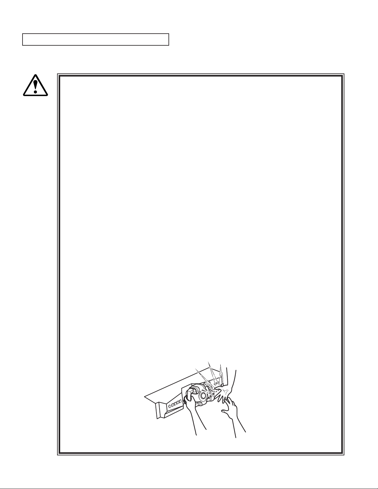
When attempting to perform this operation without powering down so that gameplay can
be restored, exercise extreme caution. Machine parts may move unexpectedly when the
power is ON. This may result in ngers being caught or severed and other injuries.
CAUTION!
Verify the Stay Lock on the top cover before attempting this procedure. If the top cover
closes during the procedure, it may result in serious injury.
If a trouble such as card jamming occurs on the card reader/writer, you are notied of the trouble on the
screen. You cannot proceed to a play unless you resolve the trouble at this time. First identify the trouble
before you begin to take action.
An error message is displayed at the top of the screen when cards become jammed.
When not discharging a card, follow the instructions below to remove the card. Removing the card may
force the game to shut down. If the game shuts down, existing customer game data will not be saved.
Remove the truss screw.
Unlock and open the cover.
Unlock.
TRUSS SCREW(1), black
M4×8
PHOTO 7. 3 a
37
www.seuservice.com
Page 46

39
www.seuservice.com
Unlock the hatch by drawing the green shaft attached to the top cover on the card reader/writer. While
drawing the shaft, open the cover up.
Remove the card jammed in the card reader/writer.
Remove the card jammed.
PHOTO 7. 3 b
While drawing the shaft, close the cover. With the top cover closed, release the green shaft. Check that
the top cover has been locked securely.
Close and lock the cover.
Secure with the truss screw.
www.seuservice.com
38
Page 47

8. PRECAUTIONS WHEN MOVING THE MACHINE
When moving the machine, be sure to unplug the power plug. Moving the machine
with the plug as is inserted can damage the power cord and cause re and electric
WARNING!
shock hazards.
When moving the machine on the oor, retract the Adjusters and ensure that Casters
make contact with the oor. During transportation, pay careful attention so that
Casters do not tread power cords and earth wires. Damaging the power cords can
cause electric shock and short circuit hazards.
Do not push the cabinet from the left/right when attempting to move the unit.
Pushing from the sides may cause the unit to tip and result in injury and damage to
parts.
Do not push on any parts made of glass (e.g. CRT screen) or plastic, as these parts may
break and result in bodily injury.
CAUTION!
FIG. 8 a
Do not push the
cabinet from the
left/right direction.
39
www.seuservice.com
Page 48

41
www.seuservice.com
In locations with low ceilings,
remove the Billboard before
moving the machine.
Place the machine on casters.
FIG. 8 b
Remove the Support Brackets
from both sides.
www.seuservice.com
40
Page 49

9. GAME DESCRIPTION
MONITOR
SPEAKER
SPEAKER
COIN INLET
STEERING WHEEL
FLUORESECT LAMP
CARD READER/WRITER
CONTROL PANEL
The following explanations apply to the case the product is functioning satisfactorily. Should there be
any moves different from the following contents, some sort of faults may have occurred. Immediately
look into the cause of the fault and eliminate the cause thereof to ensure satisfactory operation.
Whenever power is owing to the machine, the uorescent lamp is lit up. While in Advertising mode,
the monitor will go through an advertising display loop, explaining the game's content and card system,
displaying the rankings, and so on.
Sound is output from the speakers to the left and right of the monitor and on the left and right of the seat's
headrest. Sound output during Advertising mode can be turned on or off by adjusting the corresponding
setting in test mode.
The "Start" button and the 4 "View Change" buttons on top of the control panel are able to light up. They
are not lit during Advertising mode.
The "Start" button will blink when enough credits have been inserted to play the game, and cease to blink
when it is pressed to start the game. If there are still enough credits to play again after the game ends,
the button will begin to blink again. After the race starts, the "View Change" button corresponding to the
currently selected view will light up; all the others will remain unlit.
FIG. 9 a
41
www.seuservice.com
Page 50

43
www.seuservice.com
①
⑨
⑧
⑦
⑥
⑤
④
③
②
Left/Right
Forward/Backward
Game Outline
(1) START BUTTON: start game
(2) STEERING UNIT: control direction
(3) BOOST BUTTON: accelerate
(4) LICENSE CARD SLOT
(5) VIEW CHANGE BUTTON (1 - 4)
(6) PADDLE LEVER: control center of
gravity (while driving)
(7) MEMORY CARD SLOT
(8) BRAKE PEDAL: brake
(9) GAS PEDAL: control speed
FIG. 9 b CONTROL PANEL
This product is a racing game. It has two modes, RACE MODE and TIME ATTACK MODE. When the
cabinets are connected (up to four cabinets), VERSUS PLAY is available. The game features six courses
from which the players can choose freely. Each course has a time limit, and if you don't reach the goal
within the time limit, your time is up and the race will end. Passing through checkpoints and control lines
increases your time. Each course has a different number of checkpoints. A time penalty occurs when the
player leaves the course and when his car explodes (energy goes to zero).
F-ZERO LICENSE CARD
You can receive your very own machine by purchasing a license card at the start of play. You can save
player data to the card, including your name, pilot rank, pilot points, and time attack records. 1st-place
data and numbers of wins are also recorded on the card.
Pilot Points
Use your license card to earn pilot points based on your play in Race and Time Attack Modes. Once
you've collected enough points, you can get custom parts to customize your machine with!
Pilot Rank
Your pilot rank increases based on your play. Your rank can never decrease in this game.
Nintendo GameCube Memory Card
Use your Memory Card to link the game with F-ZERO GX for Nintendo GameCube. But in order to use
this special feature you must have F-ZERO GX game data on your card. Please note that the game cannot
link with a Memory Card that does not contain F-ZERO GX game data.
www.seuservice.com
42
Page 51

Game Mode
Race Mode
A single-course race. Thirty machines go head to head for rst place. In linked play, players can go headto-head against other players.
When using a license card, the game ends when the player takes rst place on every course.
Time Attack Mode
Race a set number of laps in time-trial format and ght for the best total time record. Ghost play is also
available.
Internet rankings via PC are also planned. A license card is needed for Internet rankings.
Internet Rankings
When PASSWORD DISP is set to OFF, the Internet Rankings guide is not shown during advertising.
When it is set to ON, a password is shown after playing Time Attack. Enter this password with a PC to
join the F-ZERO Internet Rankings.
The rankings will be available on the F-ZERO Ofcial Home Page (http://f-zero.jp/).
Playing the Game
(1) The Card Check Screen
If you already have a license card, place it in the License Card Slot to continue automatically to the next
screen. You can insert the Memory Card in this screen as well, but if you do not insert the Memory Card
before the license card, it will not work properly.
43
www.seuservice.com
Page 52

45
www.seuservice.com
(2) The F-ZERO LICENSE CARD Screen
Press down on the accelerator in the Card Check Screen to move to the Purchase Screen. When creating
a new card, insert the required number of coins to make a new license card. When your license card's
credits have been used up, you will be moved to the Renewing Purchase Screen.
You can insert the Memory Card in this screen as well, but if you do not insert the Memory Card before
the license card, it will not work properly.
<Creating a new card> <Renewing>
(3) The NAME ENTRY Screen (Shown the rst time a license card is purchased)
When you purchase a new license card, you are moved to the Name Entry Screen.
(Inappropriate words will be changed into asterisks.)
(4) The LICENSE CARD Screen
(Not shown if a license card is not used)
Shows your personal car and play information.
www.seuservice.com
44
Page 53

(5) The MODE SELECT Screen
Choose either RACE MODE or TIME ATTACK MODE. Different descriptions will appear below based
on the cabinet and Test Mode settings. In Versus Play, select the race mode while holding down the brake
to bypass the Versus Screen.
(6) The VERSUS Screen
(When linked and playing Race Mode.)
When you choose Race Mode in the usual way, you will be taken to the Versus Screen. Empty cabinets
will display a similar screen.
If you are using a license card, Race Mode-related data will appear. If others are also using license cards,
you can take a look at their data. The layout of the screen differs according to the number of linked
cabinets (though the information shown is the same).
* You cannot skip this screen.
<2 cabinets linked> <3-4 Cabinets linked>
45
www.seuservice.com
Page 54

47
www.seuservice.com
(7) The COURSE SELECT Screen
Select your favorite course from the six available. In Time Attack Mode, you can also congure Ghost
settings. (Use the pedal lever to choose a ghost.) If you are using a License Card, you can look at
information on each course. In Race Mode, wins, win percentage, and other data appear. In Time Attack
Mode, total time, best lap, and max speed are shown.
< Race Mode> <Time Attack Mode>
(8) The MACHINE SELECT Screen
Select your machine. You always get to choose machines, regardless of your card.
The machines you can choose from change based on the card(s) you've inserted.
- No Card: Select from the default 14 machines.
- License Card: Select from 15 machines, including your own on the far left.
- Memory Card: Adds machines from your F-ZERO GX garage on the far right.
If there are no cars in your F-ZERO GX garage, no machines will appear.
www.seuservice.com
46
Page 55

(9) The MACHINE SETTING Screen
Time Left
Laps
Energy Meter
Time
Lap Time
Rank
Top 6
You
Course Radar
Your speed
Use the graph to congure your machine.
In multiplayer Race Mode, you can view other players' machines. If you are using a License Card in
Time Attack Mode, you can look at best total times, machines used and settings.
If there is no data, NO DATA appears.
<Race Mode> <Time Attack Mode>
(10) Race
This is the racing screen. The basic controls of the machine are the steering wheel and the accelerator.
You can use the booster after the second lap, so feel free to press the button in the center of the steering
wheel. When the booster is used, the energy drain rate increases. If energy reaches zero and your machine
takes damage, your machine will ash red, you will be unable to move, and an ofcial car will come with
extra energy. If you leave the course, an ofcial car will come to return your machine to the course.
47
<Race Mode>
<Time Attack Mode>
www.seuservice.com
Page 56

49
www.seuservice.com
(11) VS RESULT Screen
When you complete the race, the results of the race appear. Results do not appear when you retire. The
display for COM races and multiplayer races are different in Race Mode. In Time Attack Mode, your
personal best and other data are also shown if you use a license card.
<Race Mode: COM> <Race Mode: Multiplayer> <Time Attack Mode>
(12) RESULTS Screen (Race Mode), TIME ATTACK RANKING Screen (Time Attack Mode)
The Results Screen shows the results of the race, while the Time Attack Ranking Screen shows the best
times recorded in the cabinet. When using a License Card, your username is automatically entered. If you
are not using a License Card, you can enter a three-letter rankings name.
<Race Mode> <Time Attack Mode>
(13) The PILOT POINTS Screen
(Only with License Card)
Gives you Pilot Points based on your race performance.
Points are added and totaled for each category.
When your Pilot Points exceed the required value, you are congratulated and moved to the Conguration
Screen. This screen also informs you of Pilot Rank promotions.
www.seuservice.com
48
Page 57

(14) The CONFIGURATION Screen
(Only with a License Card and sufcient Pilot Points)
Lets you switch out your personal machine's parts and change pilots. Changing parts and pilots costs
Pilot Points. When you change machine parts, the old parts are disposed of.
(15) Memory Card Screen
(Only with a Nintendo GameCube Memory Card inserted)
If you play with a Memory Card inserted and satisfy certain conditions, you can download special F-
ZERO AX data to your Memory Card. You can then use the downloaded data in F-ZERO GX.
49
www.seuservice.com
Page 58

(16) The PASSWORD Screen
(Only with a License Card, when playing Time Attack Mode, and when the course has completed data)
Once you complete a course in Time Attack Mode, you are taken to the Password Screen and given a
password. This password is for your best total time. It is shown every time, but it is not necessarily the
password for the race.
Enter the ID and name written to your License Card and the password shown on this screen into the
F-ZERO Ofcial Home Page to join the Internet Rankings. The Internet Rankings are announced on the
F-ZERO Ofcial Home Page (http://f-zero.jp/).
Set PASSWORD DISP to OFF in GAME ASSIGNMENTS in Test Mode to hide this screen.
You cannot continue to the next screen until the License Card is removed.
(17) The GAME OVER Screen
This screen is shown when the game is over. A reminder regarding your card is shown.
And if your license card will need to be renewed next time, this screen will indicate that.
www.seuservice.com
50
Page 59

Other Warnings
Error Display
Basic errors related to magnetic cards and memory cards cause detailed instructions to appear on the
screen. Mechanical errors in the cabinet, however, are displayed with error numbers. The following is a
description of those errors. (See 18-3.)
Error 05: Steering : I/O Error
Error 06: Steering : Overheat/Overload Error
Error 07: Steering : Encoder Error
Error 08: Steering : Excess Current Error
Secret Codes
Race Mode: "No Versus"
• Description: Play by yourself, with no VERSUS screen.
• To access: Hold down the brake when selecting a race mode in the MODE SELECT screen. This is
explained in the MODE SELECT Screen help.
Note:No Versus cannot be used when there is only one cabinet.
Race Mode: "VS BATTLE" (Human-only race)
• Description: A race with only human competitors. COM machines cannot join the race. For two to
four players.
• To access: Each participant must hold down the brake when selecting their machine in the MACHINE
SELECT screen.
Note: Cannot be used with only one cabinet or in one-player play. COM machines will always join.
Race Mode: "No Handicap"
• Description: In Race Mode, cars in the rear are given supplemental speed and can go faster (playercontrolled machines only). To turn off supplemental speed, use No Handicap.
• To access: All players (even in one-player races) must hold down the brake when selecting a machine
from the Machine Settings Screen.
Note: In Race Mode, even one-player games are handicapped, so use the above to turn handicapping
OFF.
Time Attack: Racing Staff Ghosts
• Description: Lets you race against Staff Ghosts
• To access: Hold down the brake with the cursor on "Champion Ghost" in the Course Selection Screen
and select a course.
51
www.seuservice.com
Page 60

53
www.seuservice.com
10. TEST AND DATA DISPLAY
Do not touch the machine until it has competed the initialization process and the
advertising screen has appeared. Doing so may cause the person touching the machine to
be struck by the seat. It may also prevent the machine from initializing properly. Failure
to initialize properly can lead to control malfunction and other problems.
By operating the switch unit, periodically perform the tests and data check. When installing the machine
initially or collecting cash, or when the machine does not function correctly, perform checking in
accordance with the explanations given in this section.
The following shows tests and modes that should be utilized as applicable.
This product's basic system consists of the TRIFORCE game board and the GD-ROM drive.
The product supports, therefore, the following 2 test modes:
(1) System test mode for an automatic self-diagnostic test (generally used by every product that contains
the basic system) and a coin assignment (specically used by this product) and
(2) Game test mode for testing the input/output control devices and setting the difculty level
(specically used by this product).
TABLE 10 EXPLANATION OF TEST MODE
ITEMS DESCRIPTION
INSTALLATION
OF MACHINE
MEMORY TEST
PERIODIC
SERVICING
CONTROL
SYSTEM
MONITOR
When the machine is installed, perform the following:
1. Check to ensure each is the standard setting at shipment.
2. Check each Input equipment in the INPUT TEST mode.
3. Check each Output equipment in the OUTPUT TEST mode.
4. Test on-IC-Board IC's in the SELF-TEST mode.
This test is automatically executed by selecting MEDIA BOARD
TEST, or SYSTEM INFORMATION in the Menu mode.
Periodically perform the following:
1. MEMORY TEST
2. Ascertain each setting.
3. To test each Input equipment in the INPUT TEST mode.
4. To test each Output equipment in the OUTPUT TEST mode.
1. To check each Input equipment in the INPUT TEST mode.
2. Adjust or replace each Input equipment.
3. If the problem still remains unsolved, check each equipment's
mechanism movements.
In the Monitor Adjustment mode, check to see if Monitor (Projector) adjustments are appropriate.
IC BOARD
DATA CHECK
www.seuservice.com
MEMORY TEST
Check such data as game play time and histogram to adjust the
difculty level, etc.
52
Page 61

10-1 SWITCH UNIT AND COIN METER
Never touch places other than those specied. Touching places not specied can cause
electric shock and short circuit accidents.
WARNING!
STOP
IMPORTANT!
SWITCH UNIT
Open the coin chute door, and the switch unit shown will
appear.
The functioning of each SW is as follows:
(1)TEST BUTTON: For the handling of the test button, refer to the following pages.
(TEST)
(2)SERVICE BUTTON: Gives credits without registering on the coin meter.
(SERVICE)
(3)DEMAGNETIZER SWITCH: Eliminates the on-screen color unevenness due to magnetization
(DEMAG)
Adjust the sound to the optimum volume, taking into consideration the environmental
requirements of the installation location.
Removing the Coin Meter circuitry renders the game inoperable.
FIG. 10. 1 a SWITCH UNIT
of CRT. First use this SW before performing the monitor's color
adjustment.
(4)VOLUME CONTROL: Adjusts the volume of the speakers on the left and right sides of the
(FRONT SP. VOL)
(5)VOLUME CONTROL: Adjusts the volume of the speakers on the left and right of the seat
(REAR SP. VOL)
COIN METER
Open the Cashbox Door by using the key to have
the Coin Meter appear underneath the Cashbox.
monitor.
headrest.
53
COIN METER
FIG. 10. 1 b
www.seuservice.com
Page 62

55
www.seuservice.com
10-2 SYSTEM TEST MODE
STOP
Any settings that are changed by users during TEST MODE are saved upon
exiting TEST MODE with the EXIT command in the SYSTEM MENU. If the
IMPORTANT!
unit is powered off prior to exiting, changes to settings will not take effect.
You may not enter GAME TEST MODE while the unit is reading from or
checking the GD-ROM. If error messages are displayed when exiting TEST
MODE, you should power the unit off and on again.
The following settings should be set as indicated for this product.
Coin Chute Type: Common
Service Type: Common
Network Type: Ether
10-2A SYSTEM TEST MENU
SYSTEM TEST MODE is used primarily to check if boards are functioning properly, to adjust monitor
colours and change coin/credit settings.
Press the TEST Button after powering on the unit to display the following SYSTEM MENU.
SYSTEM MENU
RAM TEST
MEDIA BOARD TEST
SYSTEM INFORMATION
JVS TEST
SOUND TEST
C.R.T. TEST
COIN ASSIGNMENTS
CLOCK SETTING
NETWORK SETTING
ENTER GAME TEST
[*******************]
→EXIT
SELECT WITH SERVICE BUTTON
AND PRESS TEST BUTTON
Press the SERVICE Button to move the cursor to the desired test item.
Move the cursor to the desired item and press the TEST Button to display each test screen.
Move the cursor to ENTER GAME TEST and press the TEST Button to enter the individual test menus
for each game. Refer to "10-3 GAME TEST MODE".
When testing is complete, move the cursor to EXIT and press the TEST Button. The game advertisement
screen should be displayed.
www.seuservice.com
54
Page 63

10-2B RAM TEST
Use RAM TEST to run a check of the TRIFORCE MAIN BOARD memory IC.
RAM TEST begins immediately upon entering this test mode.
��������RAM�TEST
����AUX�MEMORY����GOOD
PRESS�TEST�BUTTON�TO�EXIT
If "GOOD" is displayed at the right-hand side of the screen, memory IC is functioning properly.
After the test is complete, move the cursor to EXIT and press the TEST Button to return to the SYSTEM
MENU screen.
55
www.seuservice.com
Page 64

57
www.seuservice.com
10-2C MEDIA BOARD TEST
STOP
IMPORTANT!
MEDIA BOARD TEST is used to check the memory and IC on the MEDIA BOARD connected to the
TRIFORCE. Test screens and test times may differ depending on the type of MEDIA BOARD connected
to the unit.
Powering off the system during the MEDIA BOARD TEST with a DIMM BOARD will
erase the game programme data. It may be necessary to reload the data.
Always wait for the test to complete before attempting to exit.
���MEDIA�BOARD�TEST��1/2
����DIMM�BOARD(TYPE�3)
����VERSION��****
����STATUS���GOOD
����CHECKING�100%
����DIMM�TEST
����DIMM0�����-�GOOD
����DIMM1�����-�NONE
����GD-ROM����-�GOOD
PRESS�TEST�BUTTON�TO�EXIT
FIG 10. 2 c a MEDIA BOARD TEST Screen (1/2)
MEDIA BOARD TEST begins immediately upon entering this test mode.
If "GOOD" is displayed to the right of each item, the MEDIA BOARD components are functioning
properly.
Press the TEST Button to move to Screen 2/2.
Press the TEST Button on Screen 2/2 to return to the SYSTEM MENU screen.
���MEDIA�BOARD�TEST��2/2
��NETWORK�BOARD
��VERSION��****
��STATUS���GOOD
��CHECKING�100%
��NETWORK�BOARD�TEST
��RAM�CHECK�_�GOOD
����--��COMPLETED��--
PRESS�TEST�BUTTON�TO�EXIT
www.seuservice.com
FIG 10. 2 c a MEDIA BOARD TEST Screen (2/2)
56
Page 65

10-2D SYSTEM INFORMATION
Use SYSTEM INFORMATION to check version and other information for system programmes.
Screens may differ depending on the type of MEDIA BOARD connected to the unit.
����SYSTEM�INFORMATION
��MAIN�BOARD
����REGION���������****
����BOOT�VERSION���****
����FIRM�VERSION���****
����FPGA�VERSION���****
����SERIAL�NO.�***************
��MEDIA�BOARD
���DIMM�BOARD(TYPE�3)�+�GDROM
����MEMORY�SIZE����512MB
����FIRM�VERSION���****
����SERIAL�NO.�***************
���NETWORK�BOARD
����FIRM�VERSION���*****
PRESS�TEST�BUTTON�TO�EXIT
Press the TEST Button to return to the SYSTEM MENU screen.
(A) REGION
The COUNTRY CODE of the MAIN BOARD.
(B) BOOT VERSION, FIRM VERSION, FPGA VERSION
Version information for the MAIN BOARD system programmes.
(A)
(B)
(B)
(B)
(C)
(D)
(E)
(F)
(G)
(F)
(C) SERIAL NO.
Serial number of the MAIN BOARD.
(D) DIMM BOARD + GDROM
Type of MEDIA BOARD. This example shows a DIMM BOARD (TYPE 3) with a
GD-ROM DRIVE connected.
(E) MEMORY SIZE
Capacity of DIMM memory installed on the DIMM BOARD.
(F) FIRM VERSION
Version information for the DIMM BOARD system programme.
(G) SERIAL NO.
Serial number of the DIMM BOARD.
57
www.seuservice.com
Page 66

59
www.seuservice.com
10-2E JVS TEST
JVS TEST is used to verify the specs of the I/O BOARD connected to the TRIFORCE and to run input
tests.
I/O BOARD specs are displayed initially.
�����������JVS�TEST
����������INPUT�TEST
����������NEXT�NODE
��������→EXIT
NODE�������1/1
NAME�������****************
�����������I/O�BD�JVS
�����������*********
�����������Ver****
CMD�VER����1.1
JVS�VER����2.0
COM�VER����1.0
SWITCH�����2�PLAYER(S)��12�BITS
COIN�������2�SLOT
ANALOG�����8�CH
ROTARY�����0�CH
KEYCODE����0
SCREEN�����X:0�Y:0�CH:0
CARD�������0�SLOT
HOPPER�OUT�0�CH
DRIVER�OUT�22�CH
ANALOG�OUT�0�CH
CHARACTER��CHARA:0�LINE:0
BACKUP�����0
��SELECT�WITH�SERVICE�BUTTON
����AND�PRESS�TEST�BUTTON
Use the SERVICE Button to move the cursor to the desired test item.
Move the cursor to INPUT TEST and press the TEST Button to enter the INPUT TEST screen for the I/O
BOARD currently displayed.
When 2 or more I/O BOARDS are connected, move the cursor to NEXT NODE and press the TEST
Button to enter the test screen for the next I/O BOARD. The lower the NODE number, the further away
the node is from the TRIFORCE.
Move the cursor to EXIT and press the TEST Button to return to the SYSTEM MENU screen.
www.seuservice.com
58
Page 67

INPUT TEST Screen
��������������JVS�TEST
�������������INPUT�TEST
����NODE�������1/1
������SYSTEM�����00
������PLAYER�1���0000
������PLAYER�2���0000
������COIN�1�����0000
������COIN�2�����0000
������ANALOG�1���0000
������ANALOG�2���0000
������ANALOG�3���0000
������ANALOG�4���0000
������ANALOG�5���0000
������ANALOG�6���0000
������ANALOG�7���0000
������ANALOG�8���0000
PRESS�TEST�AND�SERVICE�BUTTON�TO�EXIT
(A)
(A)
(A)
(B)
(B)
(C)
(C)
(C)
(C)
(C)
(C)
(C)
(C)
On-screen values change according to the input from switches and the volume.
(A) SYSTEM, PLAYER
Values change with input from control panel/other switches.
(B) COIN
Increases with input from the COIN SWITCH. The count is cleared when exiting TEST MODE.
(C) ANALOG
Displays analog values from "0000" to "FF00".
Press the SERVICE and TEST Buttons simultaneously to return to the JVS TEST main screen.
59
www.seuservice.com
Page 68

61
www.seuservice.com
10-2F SOUND TEST
Use SOUND TEST to test sound output and to toggle the stereo/mono setting.
��������SOUND�TEST
��OUTPUT�TYPE�������STEREO
��RIGHT�SPEAKER�����OFF
��LEFT��SPEAKER�����OFF
→EXIT
SELECT�WITH�SERVICE�BUTTON
��AND�PRESS�TEST�BUTTON
(A)
(B)
(B)
Use the SERVICE Button to move the cursor to the desired test item.
Press the TEST Button to enter the selected item.
(A) OUTPUT TYPE(STEREO, MONO)
Toggle the sound output from the I/O PANEL audio output interface setting between STEREO and
MONO.
Set to STEREO in this game machine.
(B) RIGHT/LEFT SPEAKER(ON, OFF)
When set to "ON", the test sends a beep to each right and left audio output interface. Only the
word "SPEAKER" is displayed when the OUTPUT TYPE is set to "MONO", and when set to
"ON", the test sends the same beep to both the left/right audio output interfaces.
Move the cursor to EXIT and press the TEST Button to return to the SYSTEM MENU screen.
www.seuservice.com
60
Page 69

10-2G C.R.T. TEST
Use the C.R.T. TEST to adjust monitor colours and verify screen size.
COLOUR CHECK Screen
Monitor COLOUR CHECK screen is displayed initially.
Each of the colours (red, green and blue) is darkest at the far left and gets progressively lighter (32 steps)
towards the right.
Monitor brightness is set correctly if the white colour bar is black at the left edge and white at the right
edge.
�����������������C.R.T.�TEST�1/2
���������������������EDIT
�����1�������������→NEXT���������������32
RED
GREEN
BLUE
WHITE
����������SELECT�WITH�SERVICE�BUTTON
������������AND�PRESS�TEST�BUTTON
Use the SERVICE Button to move the cursor to the desired test item.
Move the cursor to EDIT and press the TEST Button to enter COLOUR ADJUST mode.
Move the cursor to NEXT and press the TEST Button to enter the SIZE CHECK screen.
SIZE CHECK Screen
C.R.T.�TEST�2/2
PRESS�TEST�BUTTON�TO�EXIT
Adjust the CHECK GRID so that the entire GRID is displayed on the screen.
Press the TEST Button to return to the SYSTEM MENU screen.
61
www.seuservice.com
Page 70

63
www.seuservice.com
COLOUR ADJUST MODE Screen
This mode is for monitors that do not have colour adjustment features.
Normally the colour should be adjusted through the monitor.
Use the SERVICE Button to move the cursor to the item to be adjusted.
Press the TEST Button to enter the selected item.
��������������C.R.T.�TEST�1/2
������������VIDEO�PARAMETER�EDIT
�����1���������������������������������32
������������BRIGHTNESS��14
������������CONTRAST����26
������������CONTRAST_R�255
������������CONTRAST_G�255
������������CONTRAST_B�255
������������AUTO�ADJUST
����������→EXIT
���������SELECT�WITH�SERVICE�BUTTON
�����������AND�PRESS�TEST�BUTTON
(A)
(B)
(C)
(D)
(E)
(F)
(A) BRIGHTNESS(10-60)
Adjust the brightness of the screen.
(B) CONTRAST(10-44)
Adjust the colour contrast.
(C) CONTRAST_R(155-255)
Adjust the RED contrast.
(D) CONTRAST_G(155-255)
Adjust the GREEN contrast.
(E) CONTRAST_B(155-255)
Adjust the BLUE contrast.
(F) AUTO ADJUST
Adjust colour settings automatically.
Move the cursor to EXIT and press the TEST Button to enter the SIZE CHECK screen.
www.seuservice.com
62
Page 71

10-2H COIN ASSIGNMENTS
Use COIN ASSIGNMENTS to set the credit rate for each coin inserted.
Use the SERVICE Button to move the cursor to the desired test item.
Press the TEST Button to change the setting or to open the detailed settings.
Move the cursor to EXIT and press the TEST Button to return to the SYSTEM MENU screen.
���������COIN�ASSIGNMENTS
��COIN�CHUTE�TYPE�������COMMON
��SERVICE�TYPE����������COMMON
��COIN�CHUTE�#1�COIN�TO�CREDIT�RATE
��1�COIN(S)�COUNT�AS�1�CREDIT(S)
��COIN�CHUTE�#2�COIN�TO�CREDIT�RATE
��1�COIN(S)�COUNT�AS�1�CREDIT(S)
��DETAIL�SETTING
��GAME�COST�SETTING
→EXIT
����SELECT�WITH�SERVICE�BUTTON
������AND�PRESS�TEST�BUTTON
COIN CHUTE TYPE…COMMON COIN CHUTE TYPE…INDIVIDUAL
(A)
(B)
(C)
(C)
(D)
(H)
���������COIN�ASSIGNMENTS
��COIN�CHUTE�TYPE�������INDIVIDUAL
��SERVICE�TYPE����������INDIVIDUAL
��COIN�CHUTE�#1�COIN�TO�CREDIT�RATE
��1�COIN(S)�COUNT�AS�1�CREDIT(S)
��DETAIL�SETTING
��GAME�COST�SETTING
→EXIT
����SELECT�WITH�SERVICE�BUTTON
������AND�PRESS�TEST�BUTTON
(A) COIN CHUTE TYPE(COMMON, INDIVIDUAL)
Adjust settings according to the specs of the cabinet COIN CHUTE.
Set to COMMON in this game machine.
COMMON
This is for cabinets where a single COIN CHUTE is used by multiple players.
Coins inserted by each player are treated as common credits.
Up to 2 COIN CHUTES (#1 and #2) may be used. The (C) COIN TO CREDIT RATE setting for COIN
CHUTE #1 and #2 may be set differently.
INDIVIDUAL
This is for cabinets with individual COIN CHUTES for each player.
Coins inserted by each player are treated as individual player credits.
The (C) COIN TO CREDIT RATE setting is used by all COIN CHUTES.
(B) SERVICE TYPE(COMMON, INDIVIDUAL)
Use this to set the function of each SERVICE Button when there is more than one SERVICE Button.
Set to COMMON in this game machine.
COMMON
Pressing any SERVICE Button enters service credits for all players.
INDIVIDUAL
Pressing the SERVICE Button enters service credits only for the corresponding player.
63
www.seuservice.com
Page 72

65
www.seuservice.com
(C) COIN TO CREDIT RATE
Set the CREDIT RATE for each coin inserted.
The "x COIN(S) COUNT AS y CREDIT(S)" setting indicates that "Inserting x coins equals y credits".
Set this to "FREE PLAY" to allow game play without credits.
When (A) COIN CHUTE TYPE is set to "COMMON", COIN CHUTE #2 settings are restricted to some
extent by the settings for COIN CHUTE #1.
(D) DETAIL SETTING
This mode allows for more detailed credit rate settings than the (C) COIN TO CREDIT RATE setting.
Changes made in DETAIL SETTING override any (C) COIN TO CREDIT RATE settings.
DETAIL SETTING Screen
���������COIN�ASSIGNMENTS
����������DETAIL�SETTING
��COIN�CHUTE�#1�MULTIPLIER
����1�COIN�COUNT�AS�1�COIN(S)
��COIN�CHUTE�#2�MULTIPLIER
����1�COIN�COUNT�AS�1�COIN(S)
��BONUS�ADDER���������NO�BONUS�ADDER
��COIN�TO�CREDIT���1�COIN(S)�1�CREDIT
→EXIT
�COIN�CHUTE�#1�OPERATION
�COIN���1��2��3��4��5��6��7��8��9
�CREDIT�1��2��3��4��5��6��7��8��9
�COIN�CHUTE�#2�OPERATION
�COIN���1��2��3��4��5��6��7��8��9
�CREDIT�1��2��3��4��5��6��7��8��9
����SELECT�WITH�SERVICE�BUTTON
������AND�PRESS�TEST�BUTTON
(E)
(E)
(F)
(G)
���������COIN�ASSIGNMENTS
����������DETAIL�SETTING
��COIN�CHUTE�#1�MULTIPLIER
����1�COIN�COUNT�AS�1�COIN(S)
��BONUS�ADDER���������NO�BONUS�ADDER
��COIN�TO�CREDIT���1�COIN(S)�1�CREDIT
→EXIT
�COIN�CHUTE�#1�OPERATION
�COIN���1��2��3��4��5��6��7��8��9
�CREDIT�1��2��3��4��5��6��7��8��9
����SELECT�WITH�SERVICE�BUTTON
������AND�PRESS�TEST�BUTTON
COIN CHUTE TYPE…COMMON COIN CHUTE TYPE…INDIVIDUAL
(E) COIN CHUTE MULTIPLIER
Use this to set how many coins will be counted for each coin inserted.
The "1 COIN COUNT AS x COIN(S)" setting indicates that "Each coin will be counted as x coins".
When the (A) COIN CHUTE TYPE is set to "COMMON", the setting may be set individually for COIN
CHUTE #1 and #2.
(F) BONUS ADDER
Use this to set the number of coins calculated with the (E) COIN CHUTE MULTIPLIER setting that
need to be inserted to get 1 bonus coin. When the (A) COIN CHUTE TYPE is set to "COMMON", the
sum of the coins for COIN CHUTE #1 and #2 is used for the calculation.
The "x COINS GIVE 1 EXTRA COIN" setting indicates that "For every x coins, 1 bonus coin is given".
Set this to "NO BONUS ADDER" to disable bonus coins entirely.
(G) COIN TO CREDIT
Use this to set how many coins calculated with the (F) BONUS ADDER setting count as 1 credit.
The "x COIN(S) 1 CREDIT" setting indicates that "Every x coins equals 1 credit."
www.seuservice.com
64
Page 73

(H) GAME COST SETTING
Use this mode to set the number of credits required to start a game.
���������COIN�ASSIGNMENTS
���������GAME�COST�SETTING
��2�CREDIT�TO�START
��1�CREDIT�TO�BUY�A�LICENSE�CARD
→EXIT
����SELECT�WITH�SERVICE�BUTTON
������AND�PRESS�TEST�BUTTON
(I) Set the number of credits required to start a game.
(J) Set the number of credits required to buy a license card.
(I)
(J)
65
www.seuservice.com
Page 74

67
www.seuservice.com
10-2I CLOCK SETTING
Use CLOCK SETTING to set the TRIFORCE internal clock.
Use the SERVICE Button to move the cursor to the item to be set.
Move the cursor to the desired item and press the TEST Button to increase values.
The max value for YEAR is "2099"; further increases return the value to "2000".
������CLOCK�SETTING
2003/06/20(FRI)��05:10:34
���������YEAR
���������MONTH
���������DAY
���������HOUR
���������MINUTE
�������→EXIT
SELECT�WITH�SERVICE�BUTTON
��AND�PRESS�TEST�BUTTON
Move the cursor to EXIT and press the TEST Button to return to the SYSTEM MENU screen.
www.seuservice.com
66
Page 75

10-2J NETWORK SETTING
STOP
IMPORTANT!
Use NETWORK SETTING to establish and test network connections.
Use the SERVICE Button to move the cursor to the desired test item.
Press the TEST Button to change the setting or to open the detailed settings.
Move the cursor to EXIT and press the TEST Button to return to the SYSTEM MENU screen.
This product should only be used with the factory settings indicated in this manual.
Selecting certain options from the screens listed below may alter settings or bring up
other screens. However, since these functions are not used by this machine, they are not
described in this manual.
In the event that settings are altered on a screen not mentioned in this manual, the
machine may cease to function properly. Restore the settings to the values shown on the
screens below.
Refer to "10-3E Network Settings" for actual network play settings.
�������NETWORK�SETTING
��NETWORK�TYPE�������ETHER
��SET�IP�ADDRESS
��CLEAR�NETWORK�SETTING
(A)
(B)
��NETWORK�TEST
->EXIT
��SELECT�WITH�SERVICE�BUTTON
����AND�PRESS�TEST�BUTTON
(A) NETWORK TYPE
Choose a type of the communication network.
Set to ETHER in this game machine.
NONE: Sets that the communication system does not perform. Sets to NONE when you
don't set the network system.
ETHER: Sets ETHER for the communication network.
MOBILE: Sets a mobile communication terminal for the communication network.
ETHER/MOBILE
DEFAULT ETHER: Set ETHER or MOBILE automatically for the communication network.
Priority is given to ETHER.
ETHER/MOBILE
DEFAULT MOBILE: Set ETHER or MOBILE automatically for the communication network.
Priority is given to MOBILE.
67
www.seuservice.com
Page 76

69
www.seuservice.com
(B) SET IP ADDRESS
This sets up the details of the communication network. Depending on the NETWORK TYPE setting, the
contents of setting vary. If setting to NONE, it does not appear.
ETHER Setting
����SET�IP�ADDRESS�1/1
REMOTE�����������DISABLE����������(C)
������IP�ADDRESS(E)
������
������SUBNET�MASK(E)
----.----.----.--- GATEWAY(E)
----.----.----.--- PRIMARY�DNS
----.----.----.--- SECONDARY�DNS
----.----.----.----
->EXIT
SELECT�WITH�SERVICE�BUTTON
AND�PRESS�TEST�BUTTON
��*******
(C) REMOTE
This option determines whether network settings will be handled automatically.
For this machine, the option should be set to DISABLE.
The other items are set up automatically. It's not necessary to change anything.
www.seuservice.com
68
Page 77

10-3 GAME TEST MODE
STOP
When changing the game conguration, changes will not be enabled until the Game
Test Mode has been completed. Be sure to exit the Game Test Mode properly after
IMPORTANT!
conguration changes.
Do not congure the game in ways not described in this text, as this may lead to
game malfunctions.
10-3A GAME TEST MENU
Select GAME TEST MODE from the System Menu screen to display the Game Test Menu screen as
follows.
Use the SERVICE Button to move the cursor to the desired test item. Press the TEST Button to enter the
selected item.
After selecting an item, read the explanations below regarding operation.
��F-ZERO�AX�TEST�MENU
��������INPUT�TEST����������������������� (10-3B)
��������OUTPUT�TEST���������������������� (10-3C)
��������GAME�ASSIGNMENTS����������������� (10-3D)
��������NETWORK�SETTING������������������ (10-3E)
��������CARD�TEST������������������������ (10-3F)
��������CALIBRATION���������������������� (10-3G)
��������RACE�RECORD���������������������� (10-3H)
��������BOOKKEEPING���������������������� (10-3I)
��������BACKUP�DATA�CLEAR���������������� (10-3J)
����->EXIT
SELECT�WITH�SERVICE�BUTTON
����AND�PRESS�TEST�BUTTON
FIG. 10. 3 a GAME TEST MENU Screen
After making changes, be sure to select EXIT and press the TEST Button in order to enable the new
settings.
Move the cursor to EXIT and press the TEST Button to return to the System Menu screen.
69
www.seuservice.com
Page 78

71
www.seuservice.com
10-3B INPUT TEST
BOOST
PADDLE RIGH T
VIEW C HANGE 1~4
ME MORY CARD SLOT
START BU TTON
STEERI NG X
GAS
BRAKE
PADDLE LE FT
MAGNE TIC CARD R /W
STEERI NG Y
L/R
F/B
Select INPUT TEST to display the following screen and check the status of input devices.
This test should be used periodically to check that each input device is functioning correctly.
�����������������������INPUT�TEST
STEERING��X�����0(~FF)�������SERVICE��������OFF(ON)
STEERING��Y�����0(~FF)�������TEST�����������OFF(ON)
PADDLE��LEFT����OFF(ON)
PADDLE��RIGHT���OFF(ON)
BOOST�����������OFF(ON)�
GAS�������������0(~FF)
BRAKE�����������0(~FF)
START�BUTTON
VIEW�CHANGE�1���OFF(ON)
VIEW�CHANGE�2���OFF(ON)
VIEW�CHANGE�3���OFF(ON)
VIEW�CHANGE�4���OFF(ON)
�������PRESS�TEST�AND�SERVICE�BUTTON�TO�EXIT
FIG. 10. 3 b a INPUT TEST Screen
Test the STEERING, GAS and BRAKE controls to ensure that they are functioning properly and that the
parameters change smoothly as each input device is operated.
If the other input devices (switches, buttons) switch from "OFF" to "ON" when operated, they are
functioning normally.
Press the SERVICE and TEST Buttons simultaneously to return to the Game Test Menu screen.
www.seuservice.com
FIG. 10. 3 b b
70
Page 79

10-3C OUTPUT TEST
BOOST
VIEW CHANGE 1 ~4
START BU TTON
STEE RING
L/R
Select STEERING and press the TEST Button to make the steering wheel turn. To
avoid injury, rst make sure that no one is touching the wheel.
CAUTION!
To avoid injury, rst check that no one is touching the steering wheel. Select
OUTPUT TEST and press the TEST Button. After initialization the steering wheel
will turn.
Selecting OUTPUT TEST and pressing the TEST Button will cause the next screen to initialize and load.
This allows you to check the status of each output device.
This test should be used periodically to check that the lamps are functioning correctly.
�����������OUTPUT�TEST�
���START�BUTTON������������OFF(ON)
���VIEW�CHANGE�1�����������OFF(ON)
���VIEW�CHANGE�2�����������OFF(ON)
���VIEW�CHANGE�3�����������OFF(ON)
���VIEW�CHANGE�4�����������OFF(ON)
���BOOST�������������������OFF(ON)
���STEERING
�����CENTER����������������OFF(ON)
�����LEFT������������������OFF(ON)
�����RIGHT�����������������OFF(ON)
->�EXIT�
���SELECT�WITH�SERVICE�BUTTON
�����AND�PRESS�TEST�BUTTON
FIG. 10. 3 c a OUTPUT TEST Screen
FIG. 10. 3 c b
71
www.seuservice.com
Page 80

73
www.seuservice.com
The START BUTTON, VIEW CHANGE 1-4, and BOOST allow you to check the status of the lights on
top of the control panel. Select each item and press the TEST Button to turn the respective light on and
off as indicated by the display to the right of the item.
Come to this screen periodically to check that the lamps light up with ON and turn off with OFF.
When you select STEERING and press the TEST Button, it will move in the selected direction for a set
period of time and stop.
Move the cursor to EXIT and press the TEST Button to return to the Game Test Menu screen.
www.seuservice.com
72
Page 81

10-3D GAME ASSIGNMENTS
Select GAME ASSIGNMENTS to display the current game settings and make changes.
Periodically come to this screen to check game settings.
������������������GAME ASSIGNMENTS
�����ADVERTISE�SOUND��������ON(OFF)
�����FORCE�FEEDBACK���������2(1~3)
�����MAGNETIC�CARD�R/W�USE��ON(ON→OFF→OUT�OF�SERVICE)
�����MEMORY�CARD�SLOT�USE���ON(ON→OFF→OUT�OF�SERVICE)
�����GAME�DIFFICULTY��������NORMAL(VERY�EASY→EASY→NORMAL→HARD→HARDEST)
�����HANDICAP���������������ON(OFF)
�����VS�BATTLE�MODE���������OFF(ON)
�����PASSWORD�DISP����������ON(OFF)
�����RACE�MODE�LAPS���������NORMAL(SET1~5)
�������1[Sonic�Oval]��������8(10→15→20→30→40)
�������2[Screw�Drive]�������6(�8→10→15→20→30)
�������3[Meteor�Stream]�����4(�6→�8→10→15→20)
�������4[Cylinder�Wave]�����3(�5→�7→�9→10→15)
�������5[Thunder�Road]������3(�5→�7→�9→10→15)
�������6[Spiral]������������3(�5→�7→�9→10→15)
->��EXIT
������������SELECT WITH SERVICE BUTTON
��������������AND PRESS TEST BUTTON
FIG. 10. 3 d GAME ASSIGNMENTS
Press the SERVICE Button and move the cursor to the setting you wish to change. Press the TEST
Button to cycle the parameters on the left of the item through its various settings.
Note that GAME DIFFICULTY, HANDICAP, VS BATTLE MODE, PASSWORD DISP and RACE
MODE LAPS are shown on the machine whose NUMBER on the NETWORK SETTING screen is set to
1.
Changing the conguration of the NUMBER 1 machine automatically follows the settings of the other
numbered machines.
ADVERTISE SOUND
Turn advertising sound output ON and OFF.
(Default setting: ON)
FORCE FEEDBACK
There are three settings for steering resistance. (Default setting: 2)
1: Weak
2: Normal
3: Strong
MAGNETIC CARD R/W USE
Congure the usability of the card reader/writer. Turn the card reader/writer on and off. (Default setting:
ON)
Set it to ON if you want to activate card reader/writer, and to OUT OF SERVICE or OFF if a malfunction
or other factor makes the card reader/writer unusable.
• If you set this option to OUT OF SERVICE, the advertising loop (demo screen) will display the
message, "The F-ZERO LICENSE CARD can not be used or purchased at this time," and users will
be unable to play with license cards.
• If you set this option to OFF, no message regarding license cards will be shown during the advertising
loop.
73
www.seuservice.com
Page 82

75
www.seuservice.com
MEMORY CARD SLOT USE
Congure Nintendo GameCube Memory Card usage. This option lets you enable or disable the memory
card slot. (Default setting: ON)
• Set this option to ON to enable compatibility with F-ZERO GX for the Nintendo GameCube.
Note that this option cannot be used if the player does not have F-ZERO GX game data.
• If you set this option to OUT OF SERVICE, the advertising loop will display the message, "Can not
use Nintendo GameCube Memory Card."
• If you set this option to OFF, no message regarding the Memory Card will be shown during the
advertising loop.
NOTES:
• If both license cards and memory cards are set to OUT OF SERVICE, the advertising loop will
display the message, "Cards cannot be used."
• If both are set to OFF, no message will be shown.
• If one of the two is set to OUT OF SERVICE, the message specic to that card will be shown.
• If one is set to OUT OF SERVICE and the other to OFF, no card instructions will be shown during the
advertising loop.
GAME DIFFICULTY
Set the game's difculty level to ve settings: VERY EASY, EASY, NORMAL, HARD, and HARDEST.
(Default setting: NORMAL)
This changes the amount of bonus time given at checkpoints and the speed of COM machines (Race
Mode only).
HANDICAP
Turns the Race Mode (COM battles, player battles) handicap ON or OFF.
(Default setting: ON)
VS BATTLE MODE
Sets COM machine participation in Race Mode ON or OFF. (Default setting: OFF)
When set to ON, players race only against other players.
However, note that COM machines will join in Single Mode and Play Solo Even when in Linked Mode.
PASSWORD DISP
Turn password display during Time Attack Mode ON and OFF. When set to ON, the password screen is
shown after racing in Time Attack Mode. This password lets users join the F-ZERO Internet Rankings
via their home computers. Please set this to OFF if Internet Rankings are not being listed. The Internet
Rankings are announced on the Ofcial F-ZERO Home Page, http://f-zero.jp/. (Default setting: ON)
RACE MODE LAPS
In Race Mode, there are six setting levels for the number of laps; Normal and Settings 1 to 5. (Default
setting: NORMAL). The game features six courses, and the number to the left of each course is its
number of laps. The number of laps in Time Attack Mode cannot be changed.
Changes to settings are not enabled until Test Mode is exited. After changing settings, be sure to exit Test
Mode.
After changing the settings, select EXIT and press the TEST Button to return to the Game Test Menu screen.
www.seuservice.com
74
Page 83

10-3E NETWORK SETTING
Select NETWORK SETTING to display the following screen and congure linked play settings.
��������NETWORK�SETTING
���LINK�NUM������2(2~4)
���GROUP���������A(A~Z)
���NUMBER��������1(1~4、
->�EXIT
���SELECT�WITH�SERVICE�BUTTON
�����AND�PRESS�TEST�BUTTON�
��������NETWORK�SETTING
���LINK�NUM�������1
LINK�NUM�NO.
)�
->�EXIT
���SELECT�WITH�SERVICE�BUTTON
�����AND�PRESS�TEST�BUTTON
FIG. 10. 3 e NETWORK SETTING Screen
Press the SERVICE Button and move the cursor to select an option to change. Press the TEST Button to
cycle through the settings shown to the left of the item.
LINK NUM
Set the number of game machines to link. Set this to "1" for the single setting. "2" or more allows
linked play. You will need to set up groups and congure the NUMBER to enable linked play.
GROUP
Used to set groups among the linked machines. For instance, if four machines are connected and you
want two groups of two, set two to "A" and the other two to "B." Ensure that you always have a group
"A".
NUMBER
Assigns a number for each machine within a group. Do not use the same number twice in one group.
Also note that you must set one machine as "1."
Changing the GAME DIFFICULTY, HANDICAP, VS BATTLE MODE, PASSWORD DISP, and
RACE MODE LAPS settings of the "1" machine will automatically change the settings of machines
numbered "2" to "4."
After changing the settings, select EXIT and press the TEST Button to return to the Game Test Menu
screen.
75
www.seuservice.com
Page 84

77
www.seuservice.com
10-3F CARD TEST
Test the functionality of or clean the card read/writer. The card read/writer should be tested and cleaned
periodically.
Clean the card reader/writer periodically.
Set the TRIFORCE's internal clock to the correct time (see section 10-2I). If the
internal clock is not set to the correct time, card play may be turned off at a different
time from the one intended.
����������CARD�TEST�
�->MAGNETIC�CARD�R/W�CHECK
���MAGNETIC�CARD�CLEANING
���MEMORY�CARD�R/W�CHECK
���CARD�CLOSE�SETTING
���EXIT
SELECT�WITH�SERVICE�BUTTON�
��AND�PRESS�TEST�BUTTON
FIG. 10. 3 f a CARD TEST Screen
MAGNETIC CARD R/W CHECK
Checks the card reader/writer.
When checking, the message "Checking the card reader/writer" is shown and a read test, write test,
and print test are automatically performed. Checking uses up one magnetic card.
If the test is completed without an error, the machine dispenses the card from the card reader/writer
slot and posts a message asking you to remove the card. When the card has been taken, the screen
reads "Succeeded to read/write."
If an error occurs, the screen produces an error display (see 18-1). If the error persists, try cleaning the
read/write heads.
MAGNETIC CARD CLEANING
This allows you to clean the card reader/writer head. For instructions on handling the cleaning card,
see "7-2 Head Cleaning".
1- Select MAGNETIC CARD CLEANING and press the TEST Button. The message "Insert the
CLEANING CARD." will appear on the screen.
2- Insert the cleaning card into the card slot.
3- When cleaning is complete, the cleaning card will be automatically ejected and the user will be
instructed to "Retrieve the CLEANING CARD."
4- Remove the cleaning card and throw it away. When the card has been removed, the screen reads
"Succeeded to cleaning."
www.seuservice.com
76
Page 85

MEMORY CARD R/W CHECK
MEMORY�CARD�R/W�CHECK
INSERT�A�MEMORY�CARD�WITH
AT�LEAST�4�EMPTY�BLOCKS.
�WRITE:[-]
�READ�:[-]
DO�NOT�INSERT�THE�MEMORY�CARD�WITH�AN
IMPORTANT�DATA.�IT�CAN�GET�DAMAGED.
EXIT:TEST�BUTTON
FIG. 10. 3 f b MEMORY CARD SLOT CHECK Screen (1)
This checks the Memory Card slot. To perform the check, you will need a Nintendo GameCube Memory
Card with four blocks of free space.
Note that there is a chance of data loss. Do not use a Memory Card that contains important information.
MEMORY CARD R/W CHECK
NOW CHECKING…(SUCCEEDED TO READ/WRITE OR FAILED TO READ/WRITE.)
WRITE:[-]
READ :[-]
DO NOT INSERT THE MEMORY CARD WITH AN
IMPORTANT DATA. IT CAN GET DAMAGED.
EXIT:TEST BUTTON
FIG. 10. 3 f b MEMORY CARD SLOT CHECK Screen (2)
Insert the Memory Card to automatically begin reading and writing tests.
Re-insertion is directed when the Card is already inserted.
If all goes well, "NOW CHECKING..." will switch to "SUCCEEDED TO READ/WRITE." and a circle
[] will appear by each item.
If there is a problem, the message "FAILED TO READ/WRITE" will appear and an "×" will be displayed
by each item.
If the "×" continues to appear after repeated tests with different memory cards, check the wiring. If you
cannot nd anything wrong with the wiring, you will need to replace the Memory Card slot.
77
www.seuservice.com
Page 86

79
www.seuservice.com
CARD CLOSE SETTING
STOP
IMPORTANT!
This allows you to assign the "card close" times. Players will not be able to use their cards from the time
that you set; cards will remain unusable until the power is reset.
Be sure to set the appropriate time given the circumstances. For instance, if you close at midnight, try
setting the time to fteen minutes before closing, at 11:45.
If you have set RACE MODE LAPS to SET5, the large number of laps may take some time to complete,
so 30 minutes before closing time (11:30) might be more appropriate.
There are three ways to set the "card close": WEEK, DAY, and OFF. Set the cursor to DAY and press the
TEST Button to change the type.
Day Time Settings
Use this to set the "card close" time to be the same every day. Congure in the same way as with WEEK.
(The default setting is 23:45.)
Users will be unable to use their cards during the time(s) that you set. Be sure to set the
appropriate time(s) based on the circumstances.
�������CLOSE�SETTING
���DAY
���TIME���23:45
��
��
��
��
�
��
->�EXIT�
SELECT�WITH�SERVICE�BUTTON�
��AND�PRESS�TEST�BUTTON
FIG. 10. 3 f d CLOSE SETTING (DAY) Screen
www.seuservice.com
78
Page 87

Weekly Time Settings
Set the "card close" time for each day. Press the SERVICE Button to select the day and the TEST Button
to change the time. Times can be changed in fteen-minute intervals. (The default setting is 0:45 for
Friday, Saturday and Sunday, and 23:45 for other days.)
������CLOSE�SETTING
���WEEK
���SU�00:45
���MO�23:45
���TU�23:45
���WE�23:45
���TH�23:45
���FR�00:45
���SA�00:45
->�EXIT�
SELECT�WITH�SERVICE�BUTTON�
��AND�PRESS�TEST�BUTTON�
FIG. 10. 3 f c CLOSE SETTING (WEEK) Screen
The OFF Setting
Disable "card close" setting.
������CLOSE�SETTING
���OFF
��
��
��
��
��
��
��
->�EXIT�
SELECT�WITH�SERVICE�BUTTON�
��AND�PRESS�TEST�BUTTON
FIG. 10. 3 f e CLOSE SETTING (OFF) Screen
After changing the settings, select EXIT and press the TEST Button to return to the Game Test Menu
screen.
79
www.seuservice.com
Page 88

81
www.seuservice.com
10-3G CALIBRATION
STOP
IMPORTANT!
To calibrate the input devices, be sure to move them to their maximum extent. The input
devices will not be calibrated unless the number displayed exceeds "10".
Calibration adjusts the controls to eliminate inconsistencies.
PULL/PUSH�HANDLE
LEFT/RIGHT�HANDLE
AND�STEP�PEDALS
STEERING�PULLING���0(~255)
STEERING�PUSHING���0(~255)
STEERING�LEFT������0(~255)
STEERING�RIGHT�����0(~255)
GAS����������������0(~255)
BRAKE��������������0(~255)
�PRESS�TEST�BUTTON�TO�CANCEL
FIG. 10. 3 g CALIBRATION Screen
This calibrates the input magnitudes for the steering wheel, accelerator (GAS), and brake.
To calibrate the steering wheel, move the handle all the way up, down, right and left, and press the pedal
all the way down. The adjustments made to the values with this program are reected in the game's
controls.
After the input devices have been moved and their input values adjusted, the screen display will change
from "PRESS TEST BUTTON TO CANCEL" to "PRESS TEST BUTTON TO EXIT". Press the TEST
Button to return to the menu screen; the input devices will be calibrated to reect the input values.
If the TEST Button is pressed while the screen displays "PRESS TEST BUTTON TO CANCEL", the
input devices will not be calibrated.
Press the TEST Button to return to the Game Test Menu screen.
www.seuservice.com
80
Page 89

10-3H RACE RECORD
Select RACE RECORD to display the twelve screens of play data.
Press the TEST Button to cycle through each screen from (1/12) to (12/12). Pressing the TEST Button
while the (12/12) screen is displayed returns you to the Game Test Menu.
NUMBER OF GAMES: Total number of games
������RACE�RECORD�1/12
��NUMBER�OF�GAMES�������00
��LICENSE�CARD�PLAY�����00
��LICENSE�CARD�BUY������00
��MEMCARD�PLAY����������00
��LINK�VS�PLAY����������00
PRESS�TEST�BUTTON�TO�CONTINUE
FIG. 10. 3 h a RACE RECORD (1/12) Screen
LICENSE CARD PLAY: Number of times license cards have been used
LICENSE CARD BUY: Number of license cards sold
MEMCARD PLAY: Number of times players have played using the Memory Card
LINK VS PLAY: Number of times link play has been played
���������������RACE�RECORD�2/12
���������MACHINE�DATA
Machine�����Play��Col�1��Col�2��Col�3��Col�4
�ORIGINAL�����0������0������0������0������0
�BFALCON������0������0������0������0������0
�GFOX���������0������0������0������0������0
�WGOOSE�������0������0������0������0������0
�FSTING�������0������0������0������0������0
�RAINP��������0������0������0������0������0
�SMOON��������0������0������0������0������0
�RTURTLE������0������0������0������0������0
�CDOLPHIN�����0������0������0������0������0
�SRAT���������0������0������0������0������0
�PINKS��������0������0������0������0������0
�BFLASH�������0������0������0������0������0
�MGULL��������0������0������0������0������0
�GTAXI��������0������0������0������0������0
�FATS���������0������0������0������0������0
������PRESS TEST BUTTON TO CONTINUE
FIG. 10. 3 h b RACE RECORD (2/12) Screen
Shows the machines and colors chosen by the players.
81
www.seuservice.com
Page 90

83
www.seuservice.com
RACE�RECORD�3/12
�����������VS�COURSE�DATA
�Course��Play��Runall���destroy��courseout�����burst
�����������������������AVG��MAX���AVG��MAX���AVG���MAX
���1�������0����0������0.0���0����0.0���0����0.0���0
���2�������0����0������0.0���0����0.0���0����0.0���0
���3�������0����0������0.0���0����0.0���0����0.0���0
���4�������0����0������0.0���0����0.0���0����0.0���0
���5�������0����0������0.0���0����0.0���0����0.0���0
���6�������0����0������0.0���0����0.0���0����0.0���0
������������PRESS�TEST�BUTTON�TO�CONTINUE
FIG. 10. 3 h c RACE RECORD (3/12) Screen
Race Mode play data by course.
• Course: Course number
• Play: Times played
• Runall: Number of times completed
• destroy: Number of rival cars which have been destroyed in a single game (shows average and
maximum)
• courseout: Number of times the player has run off course in a single game (shows average and
maximum)
• burst: Number of times the player's machine has been destroyed in a single game (shows
average and maximum)
RACE�RECORD�4/12
VS�COURSE�RANK�DATA
�
�COURSE������1�����2�����3�����4�����5�����6
�RANK�1������0�����0�����0�����0�����0�����0
�RANK�2������0�����0�����0�����0�����0�����0
�RANK�3������0�����0�����0�����0�����0�����0
�RANK�4������0�����0�����0�����0�����0�����0
�RANK�5������0�����0�����0�����0�����0�����0
�RANK�6������0�����0�����0�����0�����0�����0
�RANK�7������0�����0�����0�����0�����0�����0
�RANK�8������0�����0�����0�����0�����0�����0
�RANK�9������0�����0�����0�����0�����0�����0
�RANK�10�����0�����0�����0�����0�����0�����0
�RANK�11�����0�����0�����0�����0�����0�����0
�RANK�12�����0�����0�����0�����0�����0�����0
�RANK�13�����0�����0�����0�����0�����0�����0
�RANK�14�����0�����0�����0�����0�����0�����0
�RANK�15�����0�����0�����0�����0�����0�����0
�RANK�16�����0�����0�����0�����0�����0�����0
�RANK�17�����0�����0�����0�����0�����0�����0
�RANK�18�����0�����0�����0�����0�����0�����0
�RANK�19�����0�����0�����0�����0�����0�����0
�RANK�20�����0�����0�����0�����0�����0�����0
�RANK�21�����0�����0�����0�����0�����0�����0
�RANK�22�����0�����0�����0�����0�����0�����0
�RANK�23�����0�����0�����0�����0�����0�����0
�RANK�24�����0�����0�����0�����0�����0�����0
�RANK�25�����0�����0�����0�����0�����0�����0
�RANK�26�����0�����0�����0�����0�����0�����0
�RANK�27�����0�����0�����0�����0�����0�����0
�RANK�28�����0�����0�����0�����0�����0�����0
�RANK�29�����0�����0�����0�����0�����0�����0
�RANK�30�����0�����0�����0�����0�����0�����0
����������PRESS�TEST�BUTTON�TO�CONTINUE
Shows rank information by course for Race Mode.
www.seuservice.com
FIG. 10. 3 h d RACE RECORD (4/12) Screen
82
Page 91

RACE�RECORD�5/12(~10/12)
TIME�ATTACK�COURSE�1�(1~6)�DATA
�play�num�����:���0
�all�run�num��:���0
�courseout�avg��:���0.0��max�:��0
�burst�avg������:���0.0��max�:��0
Machine�����fastest�time���fastest�lap
ORIGINAL�����0'00''000������0'00''000
BFALCON������0'00''000������0'00''000
GFOX���������0'00''000������0'00''000
WGOOSE�������0'00''000������0'00''000
FSTING�������0'00''000������0'00''000
RAINP��������0'00''000������0'00''000
SMOON��������0'00''000������0'00''000
RTURTLE������0'00''000������0'00''000
CDOLPHIN�����0'00''000������0'00''000
SRAT���������0'00''000������0'00''000
PINKS��������0'00''000������0'00''000
BFLASH�������0'00''000������0'00''000
MGULL��������0'00''000������0'00''000
GTAXI��������0'00''000������0'00''000
FATS���������0'00''000������0'00''000
����PRESS�TEST�BUTTON�TO�CONTINUE
FIG. 10. 3 h e RACE RECORD (5/12) Screen
This is play data by course for Time Attack Mode. Course-specic information is shown on screens
(5/12) through (10/12). Press the TEST Button to change the screen (the number "X" will change in the
TIME ATTACK COURSE "X" DATA title).
• play num: The number of times each course has been played
• all run num: The number of times races have been completed
• courseout: The number of times players have run off the course (shows average and maximum)
• burst: The number of times machines have exploded (shows average and maximum)
83
www.seuservice.com
Page 92

85
www.seuservice.com
RACE�RECORD�11/12
GARAGE�GET�PARTS�
���NAME���������BUY/DISP��RATE
Brave�Eagle�������0/0������0%
Giant�Planet������0/0������0%
Megalo�Cruiser����0/0������0%
Splash�Whale������0/0������0%
Wild�Chariot������0/0������0%
Holy�Spider�������0/0������0%
Optical�Wing������0/0������0%
Dread�Hammer������0/0������0%
Silver�Sword������0/0������0%
Space�Cancer������0/0������0%
Wonder�Worm�������0/0������0%
Combat�Cannon�����0/0������0%
Cyber�Fox���������0/0������0%
Heat�Snake��������0/0������0%
Rave�Drifter������0/0������0%
Spark�Bird��������0/0������0%
Dank�Chaser�������0/0������0%
Crystal�Egg�������0/0������0%
Red�Rex�����������0/0������0%
Sonic�Soldier�����0/0������0%
Euros-01����������0/0������0%
Triangle-GT�������0/0������0%
Bluster-X���������0/0������0%
Devilfish-RX������0/0������0%
Extreme-ZZ��������0/0������0%
Punisher-4X�������0/0������0%
Impulse�220�������0/0������0%
Meteor-RR���������0/0������0%
Jupiter-Q���������0/0������0%
Comet-V�����������0/0������0%
PRESS�TEST�BUTTON�TO�CONTINUE
FIG. 10. 3 h f RACE RECORD (11/12) Screen
Shows information regarding parts swapped in the Conguration Screen. The denominator is the number
of times the part has appeared, and the numerator is the number of times it has been acquired.
RACE�RECORD�12/12
PILOT�POINT
COURSE���AVG�POINT���MAX�POINT���MIN�POINT
�1��������000��������0000��������100
�2��������000��������0000��������100
�3��������000��������0000��������100
�4��������000��������0000��������100
�5��������000��������0000��������100
�6��������000��������0000��������100
�����PRESS�TEST�BUTTON�TO�EXIT
FIG. 10. 3 h g RACE RECORD (12/12) Screen
Shows pilot points earned by course.
www.seuservice.com
84
Page 93

10-3I BOOKKEEPING
Select BOOKKEEPING to display three screens of operating status data.
Press the TEST Button to cycle through each screen from (1/3) to (3/3). Pressing the TEST Button while
the (3/3) screen is displayed returns you to the Game Test Menu.
• COIN CHUTE 1: Number of coins inserted into Coin Slot 1.
• COIN CHUTE 2: Number of coins inserted into Coin Slot 2.
BOOKKEEPING�1/3
COIN�CHUTE�1������������0
COIN�CHUTE�2������������0
TOTAL�COINS�������������0
COIN�CREDITS������������0
SERVICE�CREDITS���������00
TOTAL�CREDITS�����������00
PRESS�TEST�BUTTON�TO�CONTINUE
FIG. 10. 3 i a BOOKKEEPING (1/3) Screen
• TOTAL COINS: Total number of coins inserted into the coin slots.
• COIN CREDITS: Number of credits for the coins inserted.
• SERVICE CREDITS: Number of credits input by the SERVICE Button.
• TOTAL CREDITS: Total credits from coins and the SERVICE Button.
BOOKKEEPING�2/3
NUMBER�OF�GAMES�����������00
TOTAL�TIME�������������0D�00H�00M�00S
PLAY�TIME�����������������00H�00M�00S
AVERAGE�PLAY�TIME�������������00M�00S
LONGEST�PLAY�TIME���������00H�00M�00S
SHORTEST�PLAYTIME�������������00M�00S
PRESS�TEST�BUTTON�TO�CONTINUE
FIG. 10. 3 i b BOOKKEEPING (2/3) Screen
• NUMBER OF GAMES: Total number of games played
• TOTAL TIME: Powered-up time (length of time the machine has been on)
• PLAY TIME: Total playing time
• AVERAGE PLAY TIME: Average game play time
• LONGEST PLAY TIME: Longest game play time
• SHORTEST PLAY TIME: Shortest game play time
85
www.seuservice.com
Page 94

87
www.seuservice.com
BOOKKEEPING�3/3
TIME�HISTOGRAM
�0M00S�~�0M29S�����00
�0M30S�~�0M59S�����00
�1M00S�~�1M29S�����00
�1M30S�~�1M59S�����00
�2M00S�~�2M29S�����00
�2M30S�~�2M59S�����00
�3M00S�~�3M29S�����00
�3M30S�~�3M59S�����00
�4M00S�~�4M29S�����00
�4M30S�~�4M59S�����00
�5M00S�~�5M29S�����00
�5M30S�~�5M59S�����00
�6M00S�~�6M29S�����00
�6M30S�~�6M59S�����00
�OVER�����7M00S�����00
PRESS�TEST�BUTTON�TO�EXIT
FIG. 10. 3 i c BOOKKEEPING (3/3) Screen
TIME HISTOGRAM shows the number of plays and the respective play times.
This histogram should be referred to when setting the Game Difculty.
www.seuservice.com
86
Page 95

10-3J BACKUP DATA CLEAR
Select BACKUP DATA CLEAR to clear the contents of RACE RECORD and BOOKKEEPING. Game
settings and other data besides RACE RECORD and BOOKKEEPING will not be affected.
����BACKUP�DATA�CLEAR�
��������YES(CLEAR)�
�����->�NO�(CANCEL)�
SELECT�WITH�SERVICE�BUTTON�
��AND�PRESS�TEST�BUTTON�
FIG. 10. 3 j BACKUP DATA CLEAR Screen
To clear data, use the SERVICE Button to move the cursor to YES (CLEAR) and then press the TEST
Button. When the data has been cleared, the message "COMPLETED" will be displayed.
Press the TEST Button again to return to the Game Test Menu screen.
Move the cursor to NO (CANCEL) and press the TEST Button to return to the Game Test Menu screen
without clearing the data.
Note that when you clear this data, information about the number of times the card reader/writer has
been used will also be cleared. After data clearing the machine moves directly to card reader/writer head
cleaning mode. Refer to "7-2 Head Cleaning", when performing head cleaning.
87
www.seuservice.com
Page 96

89
www.seuservice.com
11. STEERING UNIT
In order to prevent an electric shock and short circuit, be sure to turn power off
before performing work by touching the interior parts of the product.
WARNING!
Be careful not to damage the wires. Damaged wires may cause electric shock or short
circuit or present a re risk.
Do not touch undesignated places. Touching places not designated can cause electric
shock or short circuit.
This work should be performed by the site maintenance individual or other skilled
professional. Performing work by non-technical personnel can cause electric shock
hazard.
Do not perform work other than those specied in this Manual in order to prevent
accidents during performing work and operation after performing work. Performing
work not specied in this Manual may require special training for this product. If
performing work other than those stated in this manual is required for repair, contact
the ofces herein stated in this manual or where you purchased the product from and
ask for repair or inquire how to repair.
Be very careful when soldering. Handling a soldering iron carelessly may result in a
re or a burn.
Be extremely careful when heating the heat-shrinkable tube. Failure to do so may
result in a re or burns.
CAUTION!
STOP
IMPORTANT!
Exercise extreme caution when handling the internal parts of the Steering Unit.
Watch out for damage, warping and loss. The loss of just one piece may result in
damage to or lead to faulty operation of the entire unit.
When securing the plastic-made parts, do not excessively fasten screws and nuts.
Failure to observe this may damage the parts and cause injury due to fragments
resulting from damage.
When adjusting or changing the variable resistor, set the variable resistor values on
the Volume Settings screen and check the values on the Input Test screen in Test
mode.
After adjusting or replacing a microswitch, be sure to verify that the switch turns on
and off correctly on the Input Test screen in Test mode.
www.seuservice.com
88
Page 97

If steering unit response is less than ideal and adjusting the settings on the Volume Settings screen in Test
mode has no effect, the problem is most likely due to an incorrectly engaged gear, an improperly placed
microswitch, or a broken variable resistor or microswitch.
Follow the steps listed below to correct the gear engagement, adjust the position of the switch, or replace
the variable resistor or switch.
Refer to Section 12, "Control Panel", for instructions on how to: adjust and replace the direction control
variable resistor.
11-1 ADJUSTING AND REPLACING THE Y-AXIS VR
The variable resistor that detects the forward and backward tilting operation of the steering unit is called
the Y-axis steering VR. Follow the steps listed below to adjust the gear engagement or replace the VR.
In this machine, the VR will not be damaged as long as its axle is rotating within its range of motion
when the handles on the machine are tilted to their maximum extent. Secure the VR so that its axle points
in the indicated direction and the gear is properly engaged when the handles are not being tilted.
The recommended value of the VR is within the range 70H ~ 80H when the steering unit is in the
horizontal position (see 10-3B).
The following tools and instruments are required to perform these operations:
- 3mm diameter hexagonal screwdriver or wrench
- M4-size Phillips screwdriver
- 1.5mm diameter hexagonal screwdriver or wrench
- 10mm diameter spanner
- Soldering iron
ADJUSTMENT PROCEDURE
Turn off the power.
Remove the 4 hexagon socket screws
around the boost button.
HEXAGON SOCKET SCREW (4)
M4×10, chrome
Remove the 4 truss screws holding the top
and bottom of the front steering cover in
place.
PHOTO 11. 1 a
STEERING COVER FRONT
TRUSS SCREW (4), black
M4×6
89
PHOTO 11. 1 b
www.seuservice.com
Page 98

91
www.seuservice.com
Remove the 4 truss screws holding the left and
right sides of the front steering cover in place.
TRUSS SCREW (4), black
M4×4
Detach the front steering cover. There are
several wires connected to the inside of the
cover. Remove the cover slowly and unplug
the connectors, taking care not to damage the
wiring.
PHOTO 11. 1 c
CONNECTOR (1)
Remove the 4 truss screws holding the top and
bottom of the rear steering cover in place.
STEERING COVER REAR
PHOTO 11. 1 d
TRUSS SCREW (4), black
M4×6
www.seuservice.com
90
PHOTO 11. 1 e
Page 99

Remove the 4 truss screws holding the
left and right sides of the rear steering
cover in place.
TRUSS SCREW (4), black
M4×6
PHOTO 11. 1 f
Push the rear steering cover towards the interior of the machine, pressing down on the accordion-fold
behind the cover. The Y-axis VR should now be visible inside the cover, on the left side when facing the
monitor.
NOTE: The steering unit has been removed in this photograph for better visibility. It is not necessary to
remove the steering unit when performing the actual operation.
D CUT SIDE
Installed horizontally.
SCREW (2)
M4×8, w/at & spring washers
PHOTO 11. 1 g
91
www.seuservice.com
Page 100

93
www.seuservice.com
Loosen the 2 screws holding the variable
resistor bracket in place, move the variable
resistor bracket, and adjust the gear
engagement for angle and positioning.
PHOTO 11. 1 h
Engage and secure the gear at such an angle that the D-cut side of the VR axle is horizontal and facing
downward when the steering unit is not tilted.
Manipulate the steering unit and make sure the gear is turning smoothly.
Repeat the above steps in reverse to replace the front and rear steering covers. Take care not to pinch the
wires or overtighten screws.
Note that the screws used to secure the left and right sides of the front steering cover have different
dimensions from the others. Check the screw sizes before installing them.
Adjust the variable resistor settings on the Volume Settings screen. (see 10-3G.)
Check to make sure the "STEERING Y" value on the Input Test screen is within the range 78H±8H.
REPLACEMENT PROCEDURE
Perform the steps under "Adjustment Procedure" to detach the front and rear steering covers.
Unplug the Y-axis VR wire connectors and
unfasten the harness lug holding the wiring in
place.
CONNECTOR
www.seuservice.com
HARNESS LUG
92
PHOTO 11. 1 i
 Loading...