

Page 1

1ST PRINTING FEB. 01
www.seuservice.com
TWIN TYPE
OWNER’S MANUAL
SEGA ENTERPRISES, INC. USA
MANUAL NO. 420-6507-05
Page 2
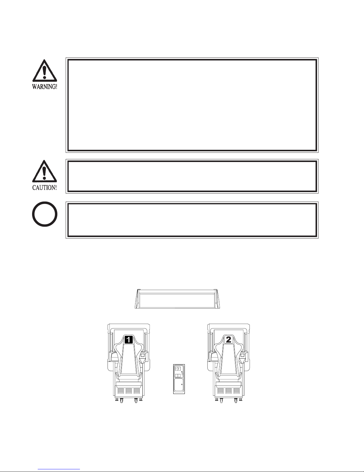
BEFORE USING THE PRODUCT, BE SURE TO READ THE FOLLOWING:
To maintain the safety:
To ensure the safe usage of the product, be sure to read the following before using the product. The following
instructions are intended for the users, operators and the personnel in charge of the operation of the product.
After carefully reading and sufficiently understanding the warning displays and cautions, handle the product
appropriately. Be sure to keep this manual nearby the product or elsewhere convenient for referring to it
when necessary.
Herein, explanations which require special attention are enclosed with dual lines. Depending on the potentially hazardous degrees, the terms of WARNING, CAUTION, etc. are used. Be sure to understand the
contents of the displays before reading the text.
Indicates that mishandling the
product by disregarding this
warning will cause a potentially
hazardous situation which can
result in death or serious injury.
For the sage usage of the product, the following pictographs are used:
Indicates “HANDLE WITH CARE.” In order to protect the human body an equipment, this
display is attached to places where the Owner’s Manual and or Service Manual should be referred
to.
Perform work in accordance with the instructions herein stated.
Instructions for work are explained by paying attention to the aspect of accident prevention. Failing to
perform work as per the instructions can cause accidents. In the case where only those who have technical expertise should perform the work to avoid hazardous situation, the instructions herein state that the
serviceman should perform such work.
Be sure to turn off power before working on the machine.
To prevent electric shock, be sure to turn off power before starting the work in which the worker touches
the interior of the product. If the work is to be performed in the power-on status, the Instruction Manual
herein always states to that effect.
Indicates that mishandling the product
by disregarding this caution will cause
a slight hazardous situation which can
result in personal injury and or material
damage.
Be sure to ground the Earth Terminal (this, however, is not required in the case where a power cord
with earth is used).
This product is equipped with the Earth Terminal. When installing the product, Connect the Earth Terminal to the “accurately grounded indoor earth terminal” by using an earth wire. Unless the product is
grounded appropriately, the user can be subject to electric shock. After performing repair, etc. for the
Control equipment, ensure that the Earth Wire is firmly connected to the Control equipment.
Ensure that the Power Supply used is equipped with an Earth Leakage Breaker.
This product does not incorporate the Earth Leakage Breaker. Using a power supply which is not
equipped with the Earth Leakage Breaker can cause a fire when earth leakage occurs.
Be sure to use fuses which meet the specified rating. (only for the machines which use fuses).
Using fuses exceeding the specified rating can cause a fire and electric shock.
Page 3

Specification changes (removal of equipment, conversion and addition) not designated by SEGA
are not allowed.
The parts of the product include warning labels for safety, covers for personal protection, etc. It is very
hazardous to operate the product by removing parts and or modifying the circuits. Should doors, lids
and protective parts be damaged or lost, refrain from operating the product, and contact where the
product was purchased from or the office herein stated. SEGA shall not be held responsible for any
accidents, compensation for damage to a third party, resulting from the specifications not designated by
SEGA.
Ensure that the product meets the requirements of appropriate Electrical Specifications.
Before installing the product, check for Electrical Specifications. SEGA products have a nameplate on
which Electrical Specifications are described. Ensure that the product is compatible with the power
supply voltage and frequency requirements of the location. Using any Electrical Specifications different
from the designated Specifications can cause a fire and electric shock.
Install and operate the product in places where appropriate lighting is available, allowing warning
labels to be clearly read.
To ensure safety for the customers, labels and printed instructions describing potentially hazardous
situation are applied to places where accidents can be caused. Ensure that where the product is operated
has sufficient lighting allowing the warnings to be read. If any label is peeled off, apply it again immediately. Please place an order with where the product was purchased from or the office herein stated.
When handling the Monitor, be very careful. (Applies only to the product w/monitor.)
Some of the monitor (TV) parts are subject to high tension voltage. Even after running off power, some
portions are still subject to high tension voltage sometimes. Monitor repair and replacement should be
performed only be those technical personnel who have knowledge of electricity and technical expertise.
Be sure to adjust the monitor (projector) properly. (Applies only to the product w/monitor.)
Do not operate the product leaving on-screen flickering or blurring as it is. Using the product with the
monitor not properly adjusted may cause dizziness or a headache to an operator, a player, or the customers.
When transporting or reselling this product, be sure to attach this manual to the product.
In the case where commercially available monitors and printers are used in this product, only the
contents relating to this product are explained herein. Some commercially available equipment has
functions and reactions not stated in this manual. Read this manual together with the specific Instruction Manual of such equipment.
•
Descriptions herein contained may be subject to improvement changes without notice.
•
The contents described herein are fully prepared with due care. However, should any question arise or
errors be found, please contact SEGA.
INSPECTIONS IMMEDIATELY AFTER TRANSPORTING THE PRODUCT TO THE LOCATION.
Normally, at the time of shipment, SEGA products are in a status allowing for usage immediately after
transporting to the location. Nevertheless, an irregular situation may occur during transportation. Before
turning on power, check the following points to ensure that the product has been transported in a satisfactory status.
Are there any dented portions or defects (cuts, etc.) on the external surfaces of the cabinet?
Are Casters and Adjusters, damaged?
Do the power supply voltage and frequency requirements meet with those of the location?
Are all wiring connectors correctly and securely connected? Unless connected in the correct direction,
connector connections can not be made accurately. Do not insert connectors forcibly.
Do power cords have cuts and dents?
Do the fuses used meet specified rating? Is the Circuit Protector in an energized status?
Are all accessories available?
Can all Doors and Lids be opened with the Accessory keys? Can Doors and Lids be firmly closed?
Page 4

TABLE OF CONTENTS
BEFORE USING THE PRODUCT, BE SURE TO READ THE FOLLOWING:
TABLE OF CONTENTS
INTRODUCTION OF THE OWNER’S MANUAL
1. HANDLING PRECAUTIONS ................................................................................................
2. PRECAUTIONS CONCERNING INSTALLATION LOCATION ........................................
3. OPERATION ...........................................................................................................................
4. NAME OF PARTS ...................................................................................................................
5. ACCESSORIES .......................................................................................................................
6. ASSEMBLING AND PRECAUTIONS...................................................................................
7. PRECAUTIONS TO BE HEEDED WHEN MOVING THE MACHINE .............................
8. CONTENTS OF GAME............................................................................ ..............................
9. EXPLANATION OF TEST AND DATA DISPLAY................................................................
9 - 1 SWITCH UNIT AND COIN METER...................................................................
9 - 2 SYSTEM TEST MODE.........................................................................................
9 - 3 GAME TEST MODE.............................................................................................
10. CONTROL PANEL.................................................................................................................
10- 1 REMOVING THE CONTROL PANEL................................................................
10- 2 ADJUSTING AND REPLACING
THE HANDLE’S (STEERING WHEEL’S) V.R. .................................................
10- 3 GREASING............................................................................................................
11. ACCELERATOR & BRAKE.................................................................................................
11- 1 ADJUSTING AND REPLACING THE V.R. .....................................................
11- 2 GREASING...........................................................................................................
12. PADDLE (WING) SHIFT.......................................................................................................
13. COIN SELECTOR..................................................................................................................
14. MONITOR...............................................................................................................................
14- 1 CAUTIONS AND WARNINGS CONCERNING THE SAFETY FOR
HANDLING THE MONITORS...........................................................................
14- 2 CAUTIONS TO BE HEEDED WHEN CLEANING THE CRT SURFACES.....
14- 3 ADJUSTMENT METHOD...................................................................................
15. REPLACING THE FLOURESCENT LAMP.........................................................................
16. PERIODIC INSPECTION TABLE.........................................................................................
17. TROUBLESHOOTING..........................................................................................................
18. GAME BOARD......................................................................................................................
18- 1 REMOVING THE BOARD.................................................................................
18- 2 FILTER BOARD..................................................................................................
18- 3 ERROR DISPLAY (DRIVE CONTROL BOARD)..............................................
19. DESIGN RELATED PARTS...................................................................................................
20. COMMUNICATION PLAY....................................................................................................
20 - 1 INSTALLATION PRECAUTIONS....................................................................
20 - 2 CONNECTING THE COMMUNICATION CABLES.......................................
20 - 3 SETTING FOR COMMUNICATION PLAY......................................................
20 - 4 CAUTIONS TO BE HEEDED WHEN USING THE TEST MODE..................
21. PARTS LIST............................................................................................................................
22. WIRE COLOR CODE TABE..................................................................................................
23. WIRING DIAGRAM..............................................................................................................
1 - 2
3 - 4
5 - 6
7
8 - 10
11 - 23
24 - 25
26 - 32
33 - 54
34
35 - 47
48 - 54
55 - 57
55
56
57
58 - 59
58 - 59
59
60 - 61
62 - 65
66 - 70
66 - 67
68
69 - 70
71 - 72
73 - 74
75 - 77
78 - 82
78 - 79
80
81 - 82
83 - 84
85 - 88
85
85 - 88
89
89
90 - 134
135
136 - 140
Page 5
SPECIFICATIONS
Installation Space : 1,632 mm (W) X 1,700 mm (D)
(64.3 in. X 66.9 in.)
Height : 1,864 mm (73.3 in.)
Weight : Approx 507 kg. ( 1,117.7 lbs.)
Power, maximum current : 555 W 6.50 A (AC 110V 50 Hz AREA)
558 W 6.50 A (AC 110V 60 Hz AREA)
536 W 5.70 A (AC 120V 60 Hz AREA)
558 W 3.30 A (AC 220V 50 Hz AREA)
547 W 3.20 A (AC 220V 60 Hz AREA)
568 W 3.30 A (AC 230V 50 Hz AREA)
544 W 3.10 A (AC 230V 60 Hz AREA)
563 W 3.10 A (AC 240V 50 Hz AREA)
533 W 2.90 A (AC 240V 60 Hz AREA)
For TAIWAN
Power, current : 575 W 7.00 A (MAX.)
440 W 5.30 A (MIN.)
MONITOR : 29 TYPE COLOR MONITOR
INTRODUCTION OF THE OWNERS MANUAL
This Owner's Manual is intended to provide detailed descriptions together with all
the necessary information covering the general operation of electronic assemblies,
electromechanicals, servicing control, spare parts, etc. as regards the product,
F355 challenge TWIN TYPE.
This manual is intended for the owners, personnel and managers in charge of
operation of the product. Operate the product after carefully reading and sufficiently
understanding the instructions. If the product fails to function satisfactorily, nontechnical personnel should under no circumstances touch the internal system. Please
contact where the product was purchased from.
Use of this product is unlikely to cause physical injuries or damages to property. However,
where special attention is required this is indicated by a thick line, the word "IMPORTANT"
and its sign in this manual.
STOP
Indicates that mishandling the product by disregarding this display can cause the
product's intrinsic performance not to be obtained, resulting in malfunctioning.
IMPORTANT
SEGA ENTERPRISES, INC. (U.S.A.)/CUSTOMER SERVICE
45133 Industrial Drive, Fremont, California 94538, U.S.A.
Phone : (415) 701-6580
Fax : (415) 701-6594
Page 6
DEFINITION OF LOCATION MAINTENANCE MAN AND SERVICEMAN
Non-technical personnel who do not have technical knowledge and expertise should
refrain from performing such work that this manual requires the location's
maintenance man or a serviceman to carry out, or work which is not explained in
this manual. Failing to comply with this instruction can cause a severe accident
such as electric shock.
Ensure that parts replacement, servicing & inspections, and troubleshooting are performed by the
location's maintenance man or the serviceman. It is instructed herein that particularly hazardous
work should be performed by the serviceman who has technical expertise and knowledge.
The location's maintenance man and serviceman are herein defined as follows:
"Location's Maintenance Man" :
Those who have experience in the maintenance of amusement equipment and vending machines,
etc., and also participate in the servicing and control of the equipment through such routine work
as equipment assembly and installation, servicing and inspections, replacement of units and
consumables, etc. within the Amusement Facilities and or locations under the management of the
Owner and Owner's Operators of the product.
Activities of Location's Maintenance Man :
Assembly & installation, servicing & inspections, and replacement of units & consumables as
regards amusement equipment, vending machines, etc.
Serviceman :
Those who participate in the designing, manufacturing, inspections and maintenance service of
the equipment at an amusement equipment manufacturer.
Those who have technical expertise equivalent to that of technical high school graduates as regards electricity, electronics and or mechanical engineering, and daily take part in the servicing &
control and repair of amusement equipment.
Serviceman's Activities :
Assembly & installation and repair & adjustments of electrical, electronic and mechanical parts of
amusement equipment and vending machines.
LISTED
U
®
L
5K92
AMUSEMENT MACHINE
Page 7
1. HANDLING PRECAUTIONS
When installing or inspecting the machine, be very careful of the following points and pay
attention to ensure that the player can enjoy the game safely.
Non-compliance with the following points or inappropriate handling running counter to the
cautionary matters herein stated can cause personal injury or damage to the machine.
Before performing work, be sure to turn power off. Performing the work
without turning power off can cause an electric shock or short circuit. In the
case work should be performed in the status of power on, this manual always
states to that effect.
To avoid electric shock or short circuit, do not plug in or unplug quickly.
To avoid electric shock, do not plug in or unplug with a wet hand.
Do not expose Power Cords and Earth Wires on the surface, (floor, passage,
etc.). If exposed, the Power Cords and Earth Wires are susceptible to damage.
Damaged cords and wires can cause electric shock or short circuit.
To avoid causing a fire or electric shock, do not put things on or damage
Power Cords.
When or after installing the product, do not unnecessarily pull the power cord.
If damaged, the power cord can cause a fire or electric shock.
In case the power cord is damaged, ask for replacement through where the
product was purchased from or the office herein stated. Using the cord as is
damaged can cause fire, electric shock or leakage.
Be sure to perform grounding appropriately. Inappropriate grounding can
cause an electric shock.
Be sure to use fuses meeting specified rating. Using fuses exceeding the
specified rating can cause a fire or electric shock.
Completely make connector connections for IC BD and others. Insufficient
insertion can cause an electric shock.
To avoid causing a fire or electric shock, do not make Specification changes
by removing, converting and making additions unless otherwise designated by
SEGA.
Be sure to perform periodic maintenance inspections herein stated.
STOP
IMPORTANT!
For the IC board circuit inspections, only the logic tester is allowed. The use
of a multiple-purpose tester is not permitted, so be careful in this regard.
When cleaning the CRT surfaces, use a soft, dry cloth. Do not apply
chemicals such as thinner, benzine, etc.
The electronic parts on the IC Board could be damaged due to human body's
static electricity. Before performing IC Board related work, be sure to
discharge physically accumulated statics by touching grounded metallic
surfaces, etc.
1
www.seuservice.com
Page 8
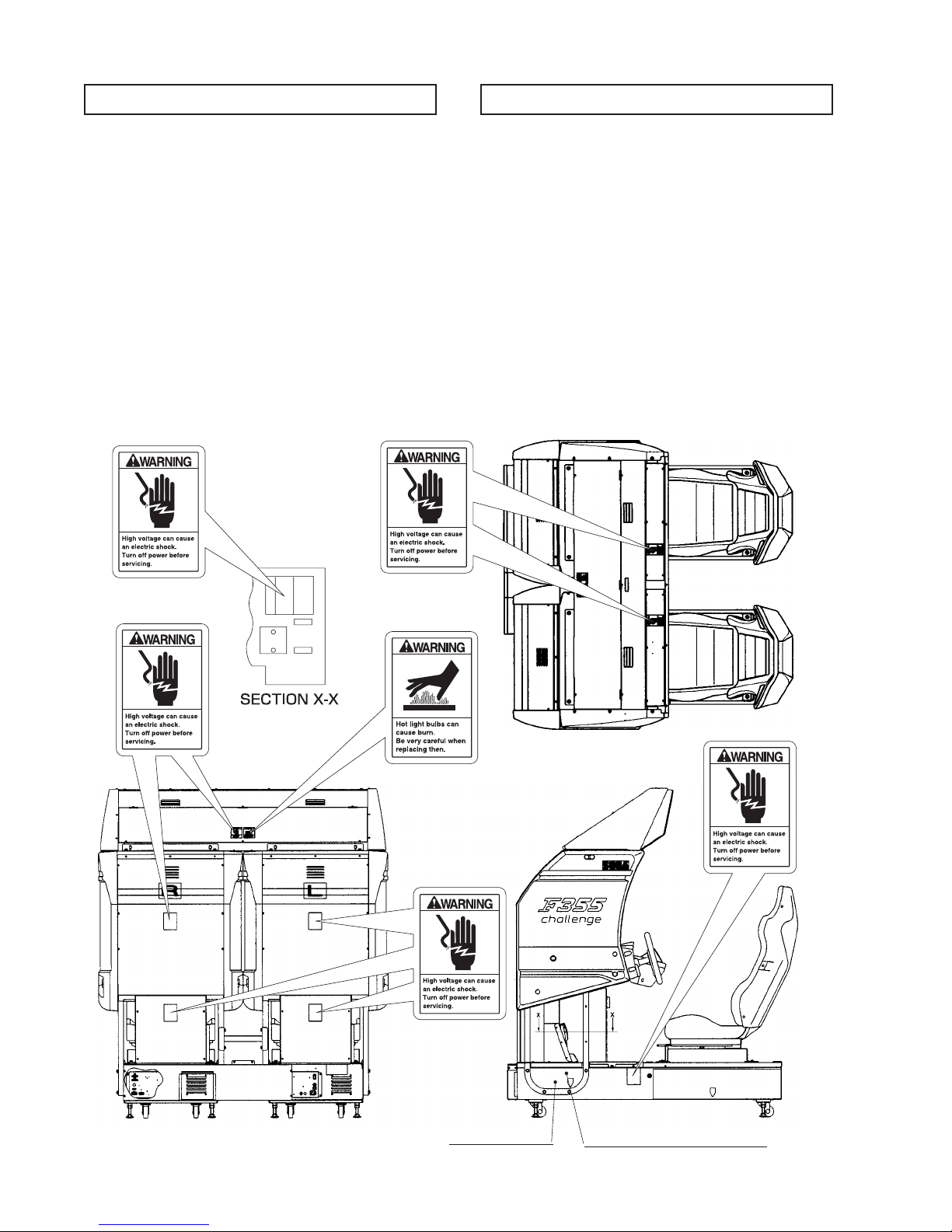
CONCERNING THE STICKER DISPLAY CONCERNING WARNING DISPLAYS
SEGA product has Stickers describing the product
manufacture No. (Serial No.) and Electrical
Specifications. Also it has a Sticker describing where to
contact for repair and for purchasing parts.
When inquiring about or asking for repair, mention the
Serial No. and Name of Machine indicated on the
Sticker. The Serial No. indicates the product register.
Identical machines could have different parts depending
on the date of production. Also, improvements and
modifications might have been made after the
publication of this Manual. In order to meet the above
situations, mention the Serial No. when contacting the
applicable places.
440-WS0002XEG
440-WS0002XEG
SEGA product has warning displays on Stickers, Labels
and or printed instructions adhered / attached to or
incorporated in the places where a potentially hazardous
situation can arise. The warning displays are intended
for accident prevention for the customers and for
avoiding hazardous situation relating to maintenance
and servicing work. There are some portions in the
Cabinet, which are subject to high tension voltage, etc.
where accidents can be caused merely by touching.
When performing the servicing work , be very careful of
the warning displays. Especially, any complex repair
and replacement work not mentioned herein, should be
performed by those technical personnel who have
knowledge of electricity and technical expertise.
For the prevention of accidents, caution any customer
whose act runs counter to the warnings, as to the effect
that he must stop the act.
440-WS0002XEG
440-WS0012XEG
440-WS0002XEG
440-WS0002XEG
www.seuservice.com
Serial No. Display
2
Electrical Specifications Display
Page 9
2. PRECAUTIONS CONCERNING INSTALLATION
LOCATION
This product is an indoor game machine. Do not install it outside. Even indoors,
avoid installing in places mentioned below so as not to cause a fire, electric shock,
injury and or malfunctioning.
Places subject to rain or water leakage, or places subject to high humidity in
the proximity of an indoor swimming pool and or shower, etc.
Places subject to direct sunlight, or places subject to high temperatures in the
proximity of heating units, etc.
Places filled with inflammable gas or vicinity of highly inflammable/volatile
chemicals or hazardous matter.
Dusty places.
Sloped surfaces.
Places subject to any type of violent impact.
Vicinity of anti-disaster facilities such as fire exits and fire extinguishers.
The operating (ambient) temperature range is from 5° C to 40° C.
Only in the case a projector is employed, the temperature range is from 5° C
to 30° C.
LIMITATIONS OF USAGE REQUIREMENTS
Be sure to check the Electrical Specifications.
Ensure that this product is compatible with the location's power supply,
voltage and frequency requirements.
A plate describing Electrical Specifications is attached to the product.
Non-compliance with the Electric Specifications can cause a fire and electric
shock.
This product requires the Breaker and Earth Mechanisms as part of the
location facilities. Using them in a manner not independent can cause a fire
and electric shock.
Ensure that the indoor wiring for the power supply is rated at 10A or higher
(AC single phase 100 ~ 120V area), and 5A or higher (AC 220 ~ 240V area).
Non-compliance with the Electrical Specifications can cause a fire and
electric shock.
Be sure to independently use the power supply equipped with the Earth
Leakage Breaker. Using a power supply without the Earth Leakage Breaker
can cause an outbreak of fire when earth leakage occurs.
Putting many loads on one electrical outlet can cause generation of heat and a
fire resulting from overload.
When using an extension cord, ensure that the cord is rated at 10A or higher
(AC 100 ~ 120V area) and 5A or higher (AC 220 ~ 240V area). Using a cord
rated lower than the specified rating can cause a fire and electric shock.
3
www.seuservice.com
Page 10
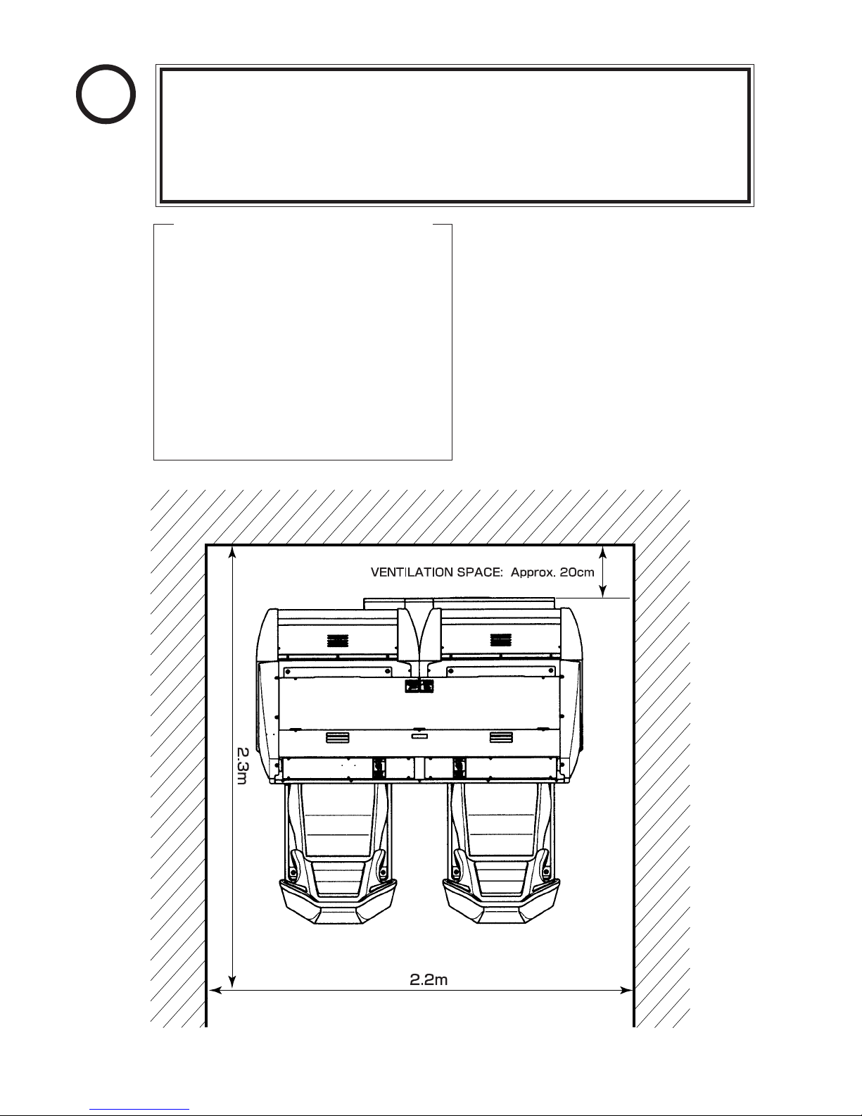
STOP
IMPORTANT!
For transporting the machine into the location's building, the minimum
For the operation of this machine, secure a minimum area of 2.2m (W) X 2.3m
MAX. 6.50 A (AC 110V 50 Hz)
MAX. 6.50 A (AC 110V 60 Hz)
MAX. 5.70 A (AC 120V 60 Hz)
MAX. 3.30 A (AC 220V 50 Hz)
MAX. 3.20 A (AC 220V 60 Hz)
MAX. 3.30 A (AC 230V 50 Hz)
MAX. 3.10 A (AC 230V 60 Hz)
MAX. 3.10 A (AC 240V 50 Hz)
MAX. 2.90 A (AC 240V 60 Hz)
necessary dimensions of the opening (of doors, etc.) are 0.85m(W) and
1.55m(H).
(D). For ventilation, provide an approximately 20cm. space between the rear
part of the cabinet and the wall.
Electric current consumption
MAX. 7.00 A (For TAIWAN)
www.seuservice.com
FIG. 2
4
Page 11
3. OPERATION
4
4
PRECAUTIONS TO BE HEEDED BEFORE STARTING THE OPERATION
To avoid injury and trouble, be sure to constantly give careful attention to the behavior and
manner of the visitors and players.
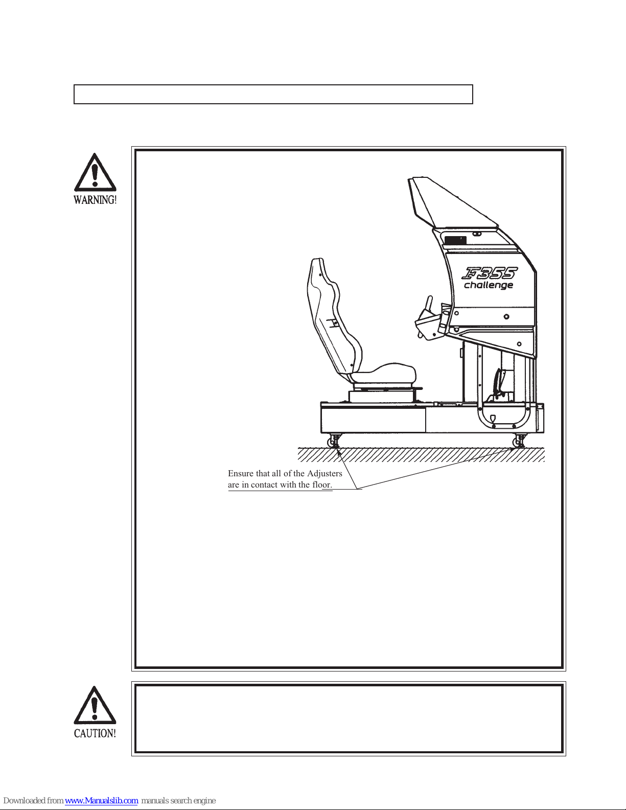
In order to avoid accidents, check the following
before starting the operation:
Check if all of the adjusters are in contact
with the surface. If they are not, the
Cabinet can move and cause an accident.
23456789012345678901234567890121234567890123
23456789012345678901234567890121234567890123
Ensure that all of the Adjusters
are in contact with the floor.
Do not put any heavy item on this product. Placing any heavy item on the
product can cause a falling down accident or parts damage.
Do not climb on the product. Climbing on the product can cause falling down
accidents. To check the top portion of the product, use a step.
To avoid electric shock, check to see if door & cover parts are damaged or
omitted.
To avoid electric shock, short circuit and or parts damage, do not put the
following items on or in the periphery of the product.
Flower vases, flowerpots, cups, water tanks, cosmetics, and receptacles/
containers/vessels containing chemicals and water.
To avoid injury, be sure to provide sufficient space by considering the potentially
crowded situation at the installation location. Insufficient installation space can
cause the customers to come into contact with or hit the others and result in injury
or trouble.
5
www.seuservice.com
Page 12

PRECAUTIONS TO BE HEEDED DURING OPERATION (PAYING ATTENTION TO CUSTOMERS)
To avoid injury and trouble, be sure to constantly give careful attention to the behavior and
manner of the visitors and players.
To avoid injury and accidents, those who fall under the following categories
are not allowed to play the game.
• Those who need assistance such as the use of an apparatus when walking.
• Those who have high blood pressure or a heart problem.
• Those who have experienced muscle convulsion or loss of consciousness when
playing video game, etc.
• Those who have a trouble in the neck and or spinal cord.
•Intoxicated persons.
•Pregnant women or those who are in the likelihood of pregnancy.
• Persons susceptible to motion sickness.
• Persons whose act runs counter to the product's warning displays.
To avoid injury resulting from falling down, and electric shock due to spilled
drinks, instruct the player not to place heavy items or drinks on the product.
To avoid electric shock and short circuit, do not allow customers to put hands
and fingers or extraneous matter in the openings of the product or small
openings in or around the doors.
To avoid falling down and injury resulting from falling down, immediately
stop the customer's leaning against or climbing on the product, etc.
To avoid electric shock and short circuit, do not allow the customers to
unplug the power plug without a justifiable reason.
Immediately stop such violent acts as hitting and kicking the product. Such
violent acts can cause parts damage or falling down, resulting in injury due to
fragments and falling down.
Instruct the Player to take firm hold of the Steering Wheel when in play. The
Steering Wheel is equipped with reaction mechanism. Holding the Steering
Wheel lightly while playing the game can cause a contingent accident.
Instruct the customer, other than the Player, not to touch the operation device
when in play. Touching the operation device during play can cause accidents
and trouble between customers.
This product has a difference in grade. To avoid falling down accident,
instruct the player to watch his/her step when getting on/off the Floor Base.
Instruct the Player to adjust the seat before playing the game. Playing the
game in a forcible posture can cause a contingent accident.
This product is designed for players taller than 130cm and shorter than
210cm. To avoid accidents, instruct the customers who do not meet the
height requirements to refrain from playing the game.
www.seuservice.com
6
Page 13
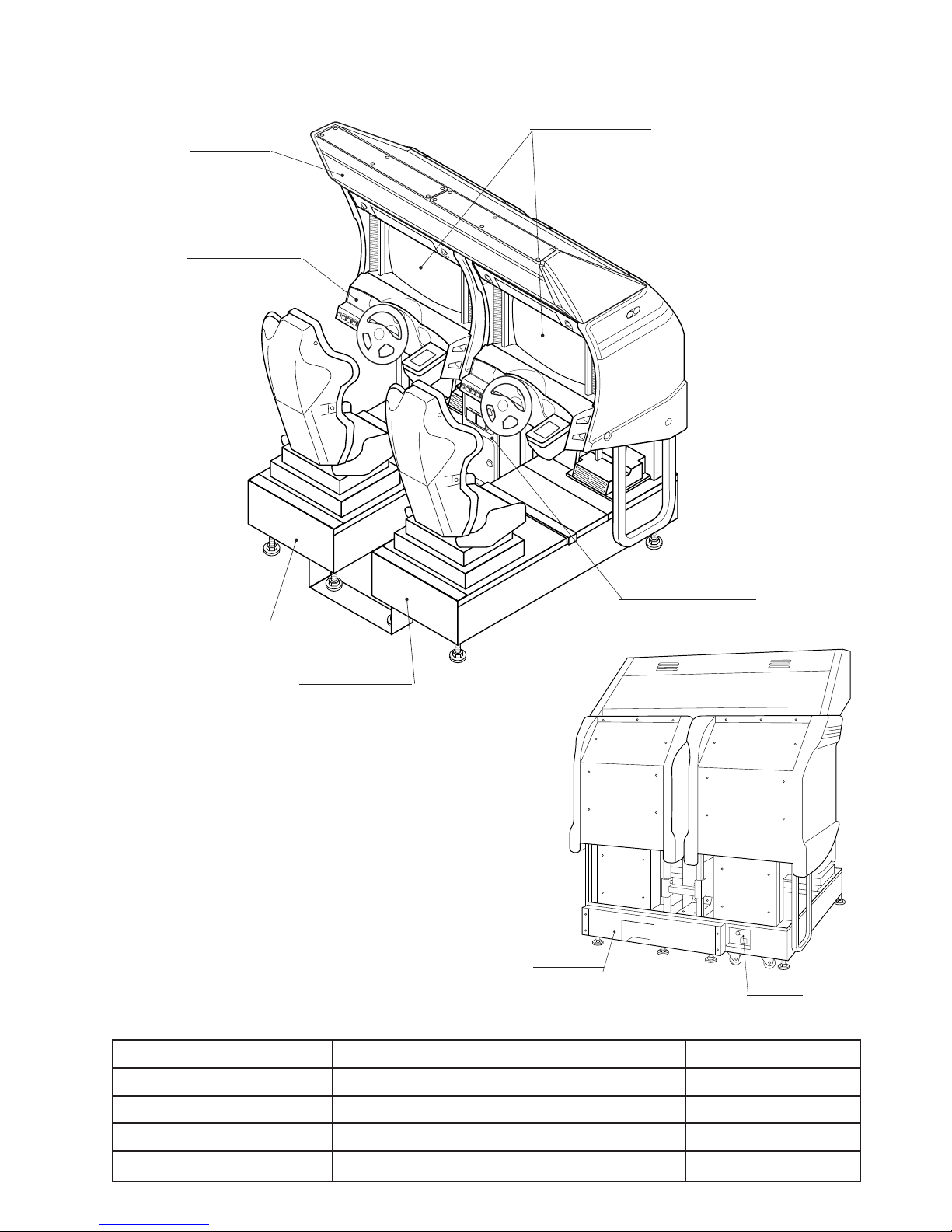
4. NAME OF PARTS
BILLBOARD
CONTROL PANEL
29 TYPE MONITOR
1P SIDE COCKPIT
TABLE 4
COIN CHUTE TOWER
2P SIDE COCKPIT
FIG. 4 a OVERVIEW
AC COVER
AC UNIT
FIG. 4 b REAR VIEW
COCKPIT (per seat) 820 mm X 1,645 mm X 1,520 mm 228 kg
COIN CHUTE TOWER 305 mm X 515 mm X 570 mm 15 kg
BILLBOARD 1,609 mm X 617 mm X 354 mm 36 kg
When assembled 1,632 mm X 1,700 mm X 1,864 mm Approx. 507 kg
Width X Length X Height Weight
7
www.seuservice.com
Page 14
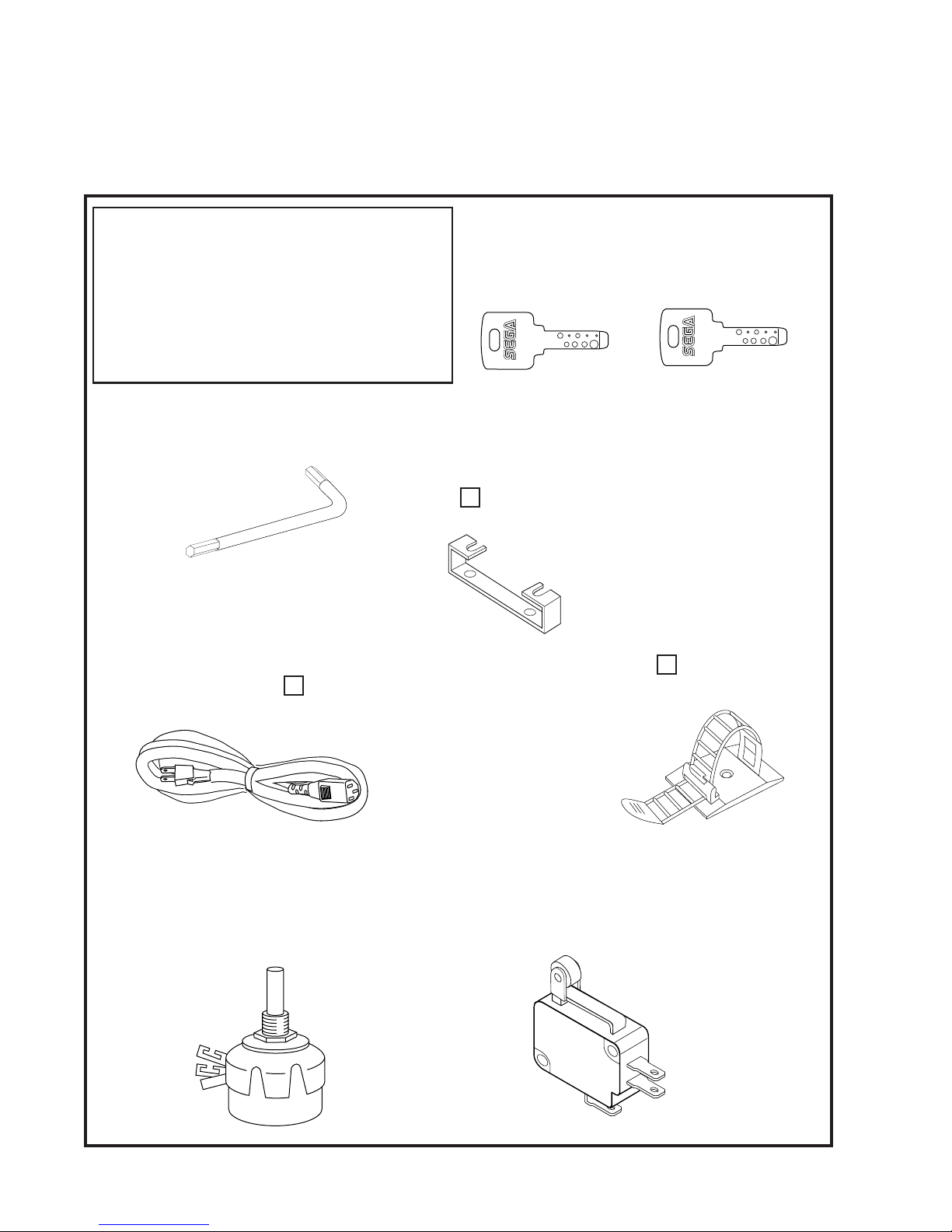
5. ACCESSORIES
When transporting the machine, make sure that the following parts are supplied.
TABLE 5 ACCESSORIES
DESCRIPTION OWNERS MANUAL
Part No. (Qty.)
420-6507-05 (1)
Note
Figures
If Part No. has no description, the Number has not been
registered or can not be registered. Such a part may not
be obtainable even if the customer desires to purchase it.
Therefore, ensure that the part is in safekeeping with you.
TAMPERPROOF†WRENCH
M8 540-0009-01 (1)
TOOL
AC Cable (Power Cord)
600-6724
600-6729
600-6618 (1) AC 220 ~ 240V AREA
Used for installation, see 5 of Section 6.
(1) AC 110V AREA
KEY MASTER
220-5576 (2)
For opening/closing
the doors
JOINT PLATE
DYN-0020 (1)
Used for installation,
see 2 of Section 6.
KEY
(2)
For the CASHBOX DOOR
The Keys are inside the Coin
Chute Door at the time of
shipment from the factory.
CORD CLAMP
280-5009-01 (1)
Used for securing the
power cord.
see 5 of Section 6.
VOL CONT B-5K OHM
220-5373
220-5484
Spare, see Section 10, 11.
www.seuservice.com
(1)
SW MICRO TYPE
509-5357 (1)
For spare, refer to Section 12.
8
Page 15
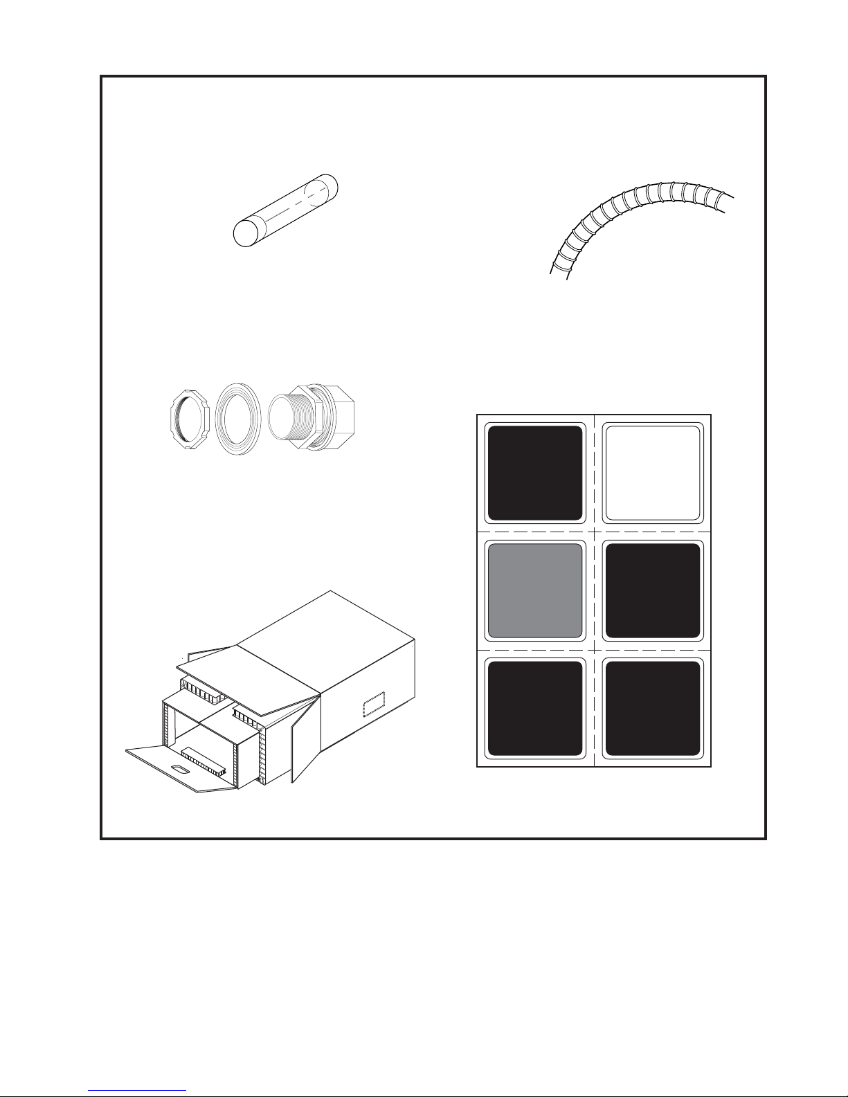
FUSE 7A
514-5036-7000 (2)
Spare, see Section 17.
CONN 22
310-5051-22 (2)
For communication play, refer to Section 20.
FLEX TUBE
310-5050-220090 (1)
For communication play, refer to Section 20.
STICKER NO.OPTION
421-11210 (1)
For communication play, refer to Section 20.
CARTON BOX
601-10835 (1)
Used for transporting the Game Board.
Refer to the following.
C
H
E
C
K
S
ID
E
3
5
7
4
6
8
9
www.seuservice.com
Page 16
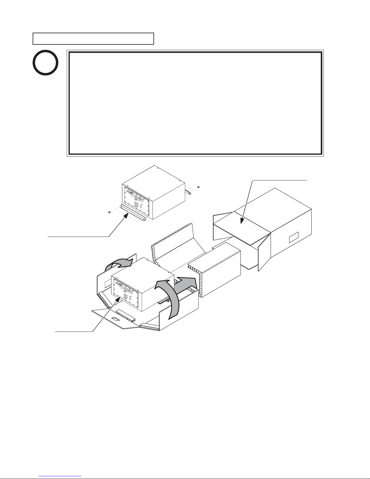
HOW TO USE THE CARTON BOX
STOP
When requesting for the replacement/repair of this product's Game Board
(NAOMI BOARD), follow the instructions below. Transporting the Game Board
in an undesignated status is unacceptable. An erroneous handling can cause parts
IMPORTANT!
damage.
• Put the Game Board in the Carton Box together with the Shield Case. Do not
• By paying careful attention to the following Figure and the direction shown
• When putting the Shield Case in the Carton Box, do not remove Leg Brackets.
• The projected portions of the packing material is intended for cushioning.
SHIELD CASE BRACKET
unnecessarily disassemble nor remove parts.
by on-Carton-Box printing, put the Shield Case in the Carton Box.
Therefore, do not bend the projected portions.
"CHECK SIDE" Display
C
H
EC
K
SID
E
FILTER BOARD
Fold the packing material shown in the Figure, enfold the Shield Case and put it in the Carton
Box. Positioning the Shield Case upside down or packing in the manner different from what is
shown in this Figure can cause the Game Board and other parts to be damaged.
www.seuservice.com
10
Page 17
6. ASSEMBLING AND PRECAUTIONS
Perform assembly work by following the procedure herein stated. Failing to
comply with the instructions can cause electric shock hazard.
Assembling should be performed as per this manual. Since this is a complex
machine, erroneous assembling can cause an electric shock, machine damage
and or not functioning as per specified performance.
Perform connector connection securely. Insufficient insertion can cause
electric shock and short circuit hazards.
This work should be performed by the Location's Maintenance Man or
Serviceman. Working by those who do not have technical expertise can cause
such severe accidents as electric shock. Failing to perform work in
accordance with the explanations given in this manual can cause such severe
accidents as electric shock to the player during operation.
Be careful so as not to damage wiring. Damaged wiring can cause electric
shock and short circuit hazards.
When carrying out the assembly work, follow the procedure in the following 7-item sequence:
ASSEMBLING THE COCKPIT
1
SECURING IN PLACE (ADJUSTER ADJUSTMENT)
2
INSTALLING THE BILLBOARD
3
INSTALLING THE AC COVERS (WIRING CONNECTION)
4
POWER SUPPLY, AND EARTH CONNECTION
5
TURNING POWER ON
6
ASSEMBLING CHECK
7
11
www.seuservice.com
Page 18
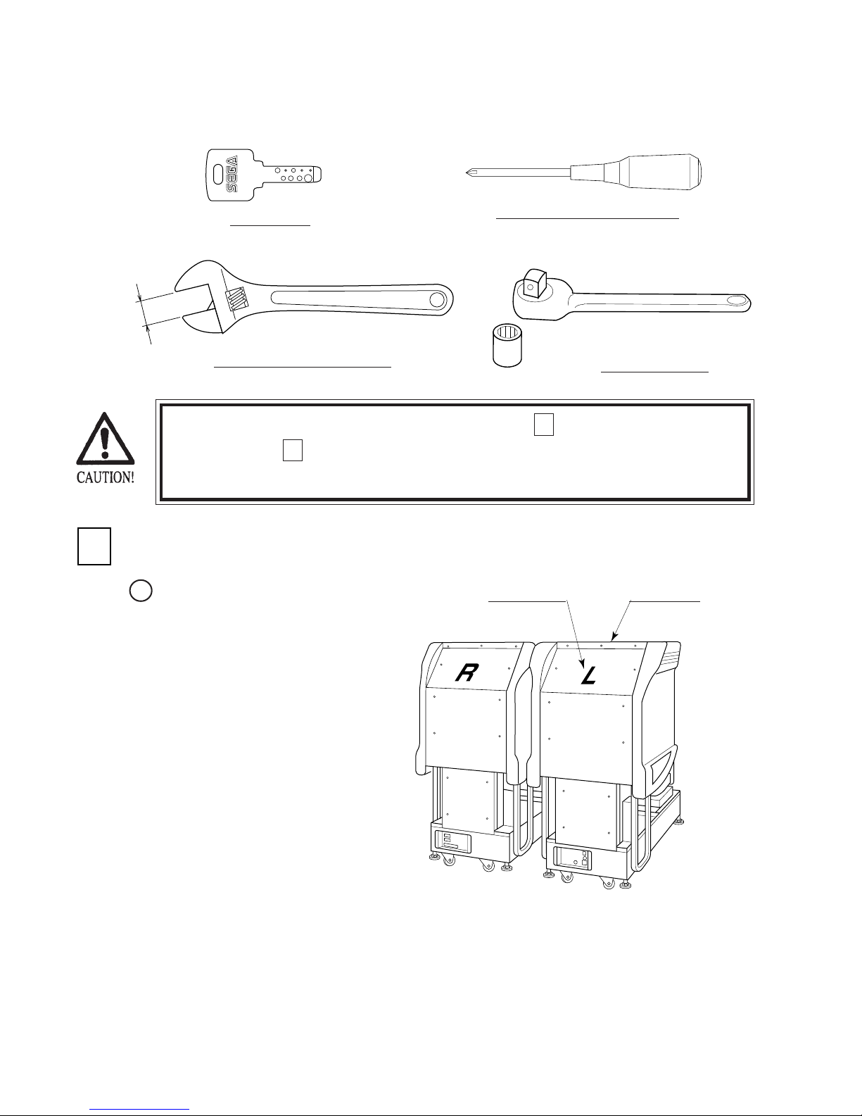
Note that the master key and the cashbox door key (accessories) in addition to the tools such as
1
a Phillips type screwdriver, wrench for M16 hexagon bolt and socket wrench are required for
the assembly work.
MASTER KEY
24mm
WRENCH (for M16 hexagon bolt)
Perform the tightening of hexagon bolts described in 1 above after adjusting the
adjusters as per 2 . Make sure that until the adjuster adjustments are made, keep
the hexagon bolts tightened temporarily.
ASSEMBLING THE COCKPIT
Place the two cockpits side by
1
side. Position the 1P cabinet at the
left-hand side as viewed facing the
monitor. STICKER "L" is attached
on the back of 1P cabinet, and
STICKER "R" on the back of 2P
cabinet.
PHILLIPS TYPE SCREWDRIVER
SOCKET WRENCH
STICKER "L"
1P COCKPIT
www.seuservice.com
FIG. 6. 1 a
12
Page 19

Install the coin chute tower in
2
between both cabinets. Open the
coin chute door and the cashbox
door to secure with the 4 hexagon
bolts from inside the doors. At this
time, make sure that the bolts are
fastened temporarily.
COIN CHUTE DOOR
HEXAGON BOLT (4)
M8 X 20, w/spring washer,
flat washer used.
Install the joint pipe on to the
3
backside of both cabinets by
securing with 4 hexagon bolts
(at this time, temporarily).
HEXAGON BOLT (black) (4)
M8 X 25, w/spring washer,
flat washer used.
COIN CHUTE TOWER
FIG. 6. 1 b
JOINT PIPE
FIG. 6. 1 c
Attach the blind cap to the head of
4
each hexagon bolt (6 bolts on each
side of the monitor ... a total of 12)
by pressing it in.
BLIND CAP (12)
SPG-0005
13
FIG. 6. 1 d
www.seuservice.com
Page 20
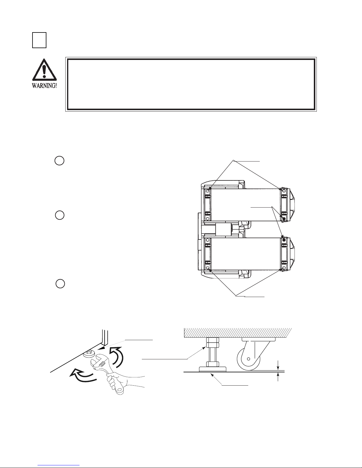
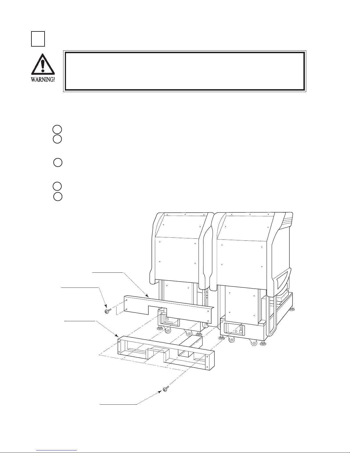
SECURING IN PLACE (ADJUSTER ADJUSTMENT)
2
Make sure that all of the adjusters are in contact with the floor. If they are
not, the cabinet can move and cause an accident.
Be sure to use plural workers to perform work. Depending on the specific
work, there are some cases in which working by one person alone can cause
personal injury and parts damage.
This machine has 8 casters and 8 adjusters (Fig. 6.2a). When the installation position is
determined, cause the adjusters to come into contact with the floor directly, make adjustments in
a manner so that the casters will be raised approximately 5mm. from the floor and make sure
that the machine position is level.
1
Move the machine to the
installation position. When
installing the machine against or
close to a wall, be sure to secure a
passage space to enable the player
to take a ride in the machine.
Attach the joint plate for the 2
2
internal adjusters shown. First,
cause the other 6 adjusters to come
into contact with the floor. Make
adjuster adjustments with a wrench
in a manner to ensure the
machine's position is level
(Fig.6.2b).
After making adjustments, fasten
3
the adjuster nut upward and secure
the height of the adjuster
(Fig.6.2b).
ADJUSTER
Attach the
joint plate
CASTER
FIG. 6. 2 a BOTTOM VIEW
www.seuservice.com
ADJUSTER
CASTER
FASTEN UPWARD.
Approx.5mm
ADJUSTER
FIG. 6. 2 b ADJUSTER
14
Page 21
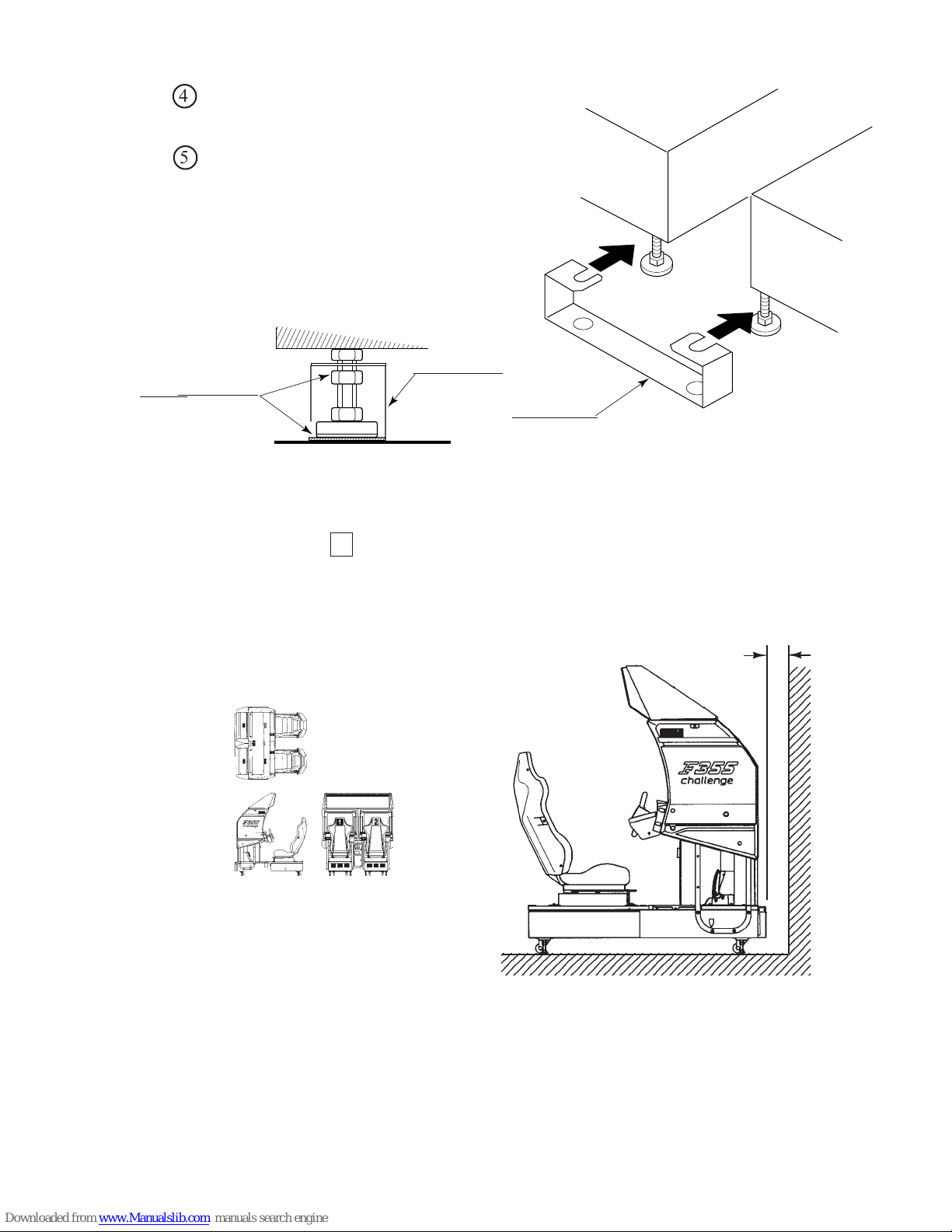
Insert the notch portions of the joint
6
123
123
123
123
123
123
123
123
123
123
123
123
123
123
123
123
123
123
123
123
123
123
123
123
123
123
123
123
123
123
123
123
123
123
123
123
4
plate to the 2 adjuster bolt portions.
Lower the adjuster and fasten the
5
nut upward. Secure the joint plate
with the nuts and the bottom of
adjuster.
Secure the joint plate
by fastening the nuts
and the bottom of
adjuster.
After securing the height of the adjusters, tighten all of the hexagon bolts which were fastened
temporarily as per 1 above.
JOINT PLATE
JOINT PLATE
FIG. 6. 2 c JOINT PLATE
FIG. 6. 2 d
Refer to this Fig. (Scale:1/100)
for the layout of the place of
installation.
Approx. 20cm
234567890123456789012345678901212345
FIG. 6. 2 e
Provide sufficient space so as to
allow for ventilation by the
ventilation fan.
15
www.seuservice.com
Page 22
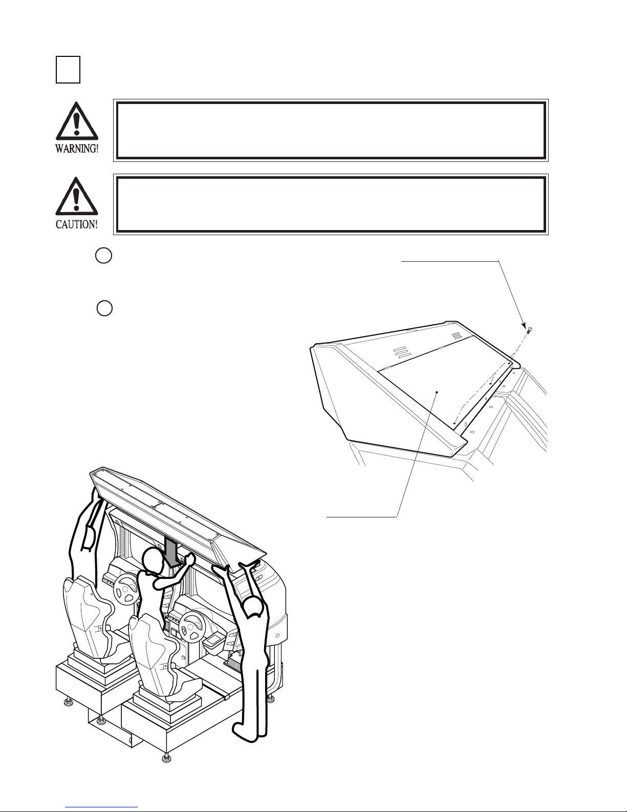
INSTALLING THE BILLBOARD
3
The Billboard is extremely heavy, weighing approximately 36kg. When installing
it, be sure to use plural workers. Performing work by one person can cause an
accident.
To perform work safely and securely, be sure to prepare a step which is in a
secure and stable condition. Performing work without using the step can cause
violent falling down accidents.
Mount the BILLBOARD over the
1
cabinet. When performing work, be
sure to use 3 or more workers.
Take out 3 Truss Screws to open the
2
BILLBOARD LID.
TRUSS SCREW (3) black
M4 X 8
BILLBOARD LID
FIG. 6. 3 a
www.seuservice.com
For performing work,
use 3 or more workers.
16
Page 23
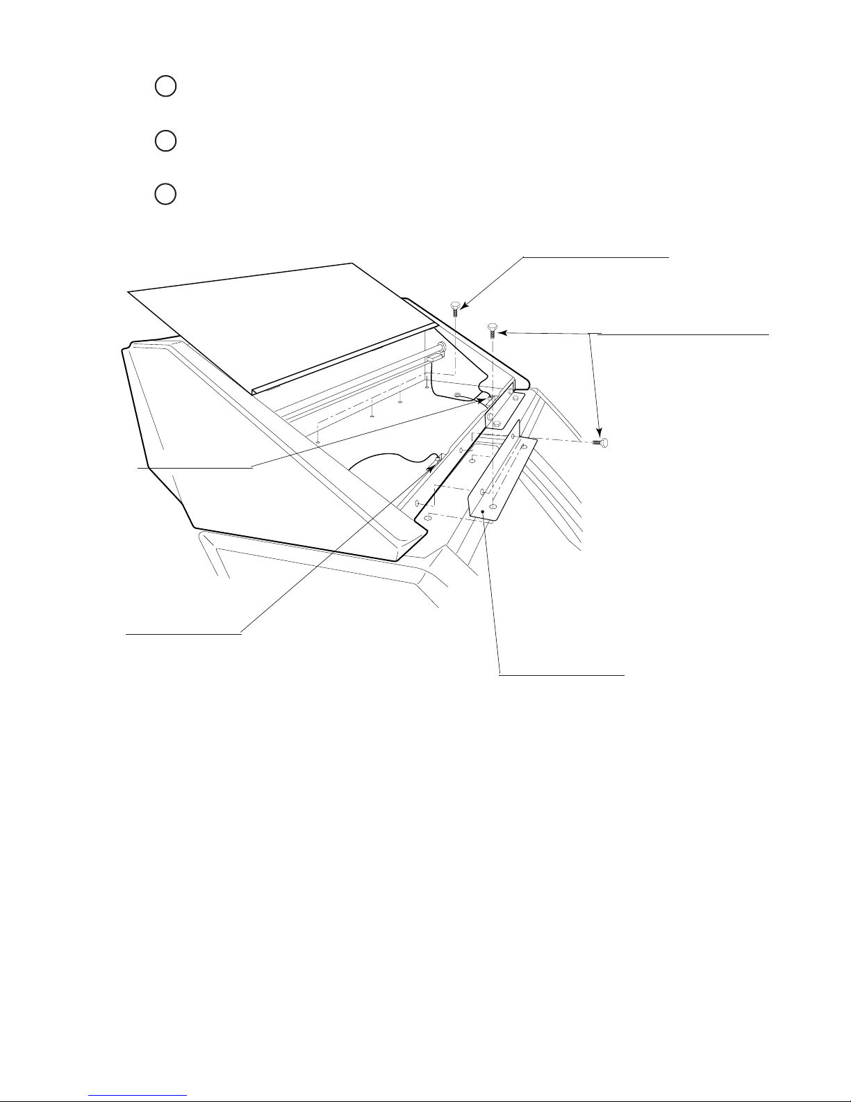
By fastening 3 Hexagon Bolts to the inner part of the BILLBOARD inside, secure the
3
BILLBOARD to the cabinet.
Secure the 2 BILLBOARD HOLDERs with 4 Hexagon Bolts for each to secure the cabinet and
4
BILLBOARD.
5
Connect the left & right connectors. Close the BILLBOARD LID and secure with 3 Truss
Screws.
Connect the connector.
HEXAGON BOLT (4) black
M8 X 25, w/spring washer,
flat washer used
HEXAGON BOLT (4 each) black
M8 X 25, w/spring washer,
flat washer used
Connect the connector.
BILLBOARD HOLDER
FIG. 6. 3 b
17
www.seuservice.com
Page 24
INSTALLING THE AC COVERS (WIRING CONNECTION)
4
Before starting to work, ensure that the Power SW is OFF. Failure to observe
this can cause electric shock and short circuit hazards.
Use care so as not to damage wirings. Damaged wiring can cause electric
shock and short circuit hazards.
The AC cover is used for protecting the wiring and optic fiber cables. When performing the work,
be very careful so as not to cause damage by catching them. Pay due attention to handling optic
fiber cables in particular. Ensure not to cause breakage to the cables due to excessive bending.
1
Attach AC COVER A to the back of the cabinet (Fig. 6.4) by securing with 5 screws.
Make wiring connections between both cabinets & the coin chute tower. Insert the supplied
2
wiring connectors to the corresponding ones which have an identical color and the same number
of pins.
3
Insert the optic fiber cables to the optic fiber connectors in a manner as applicable. There are
"TX" and "RX" connectors. Make sure to connect the "TX" connector of one cabinet to the
"RX" connector of the other cabinet (see Sec. 20).
4
Secure the wiring and optic fiber cable with cord clamps in AC COVER A.
Install AC COVER B. Insert AC COVER B to AC COVER A from above and secure with 4
5
screws.
AC COVER B
SCREW (2) black
M4 X 8, w/flat &
spring washers
AC COVER A
SCREW (5) black
M4 X 8, w/flat & spring washers
FIG. 6. 4
www.seuservice.com
18
Page 25
POWER SUPPLY, AND EARTH CONNECTION
5
Be sure to independently use the power supply socket outlet equipped with an
Earth Leakage Breaker. Using a power supply without an Earth Leakage
Breaker can cause a fire when electric leakage occurs.
Ensure that the "accurately grounded indoor earth terminal" and the earth wire
cable are available (except in the case where a power cord plug with earth is
used). This product is equipped with the earth terminal. Connect the earth
terminal and the indoor earth terminal with the prepared cable. If the
grounding work is not performed appropriately, customers can be subjected to
an electric shock, and the product's functioning may not be stable.
Ensure that the power cord and earth wire are not exposed on the surface
(passage, etc.). If exposed, they can be caught and are susceptible to damage.
If damaged, the cord and wire can cause electric shock and short circuit
accidents. Ensure that the wiring position is not in the customer's passage
way or the wiring has protective covering.
After wiring power cord on the floor, be sure to protect the power cord.
Exposed power cord is susceptible to damage and causes an electric shock
accident.
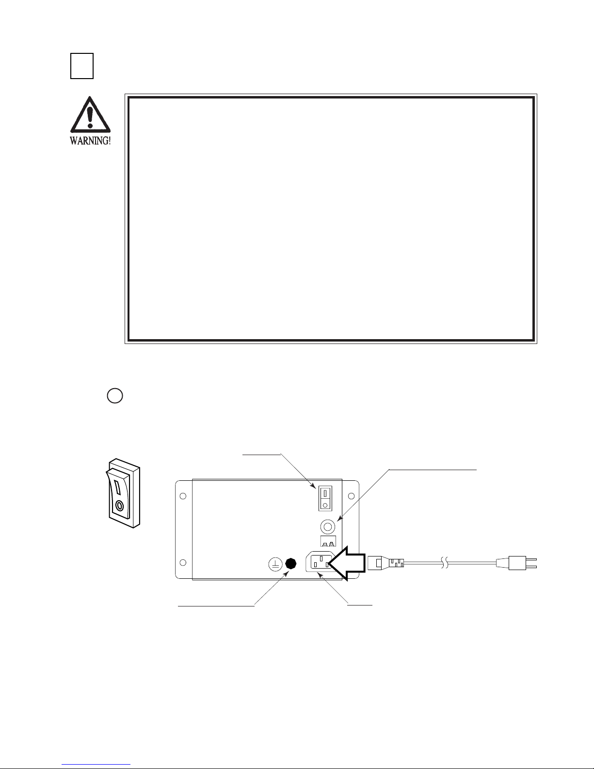
The AC Unit is mounted on the 1P COCKPIT. The AC Unit incorporates the Main SW, earth
terminal and Inlet.
1
Ensure that the Main SW is OFF.
MAIN SW
CIRCUIT PROTECTOR
Main SW off
EARTH TERMINAL
Connect with the
indoor earth terminal.
INLET
To the Power Supply
Socket outlet
FIG. 6. 5 a AC unit
19
www.seuservice.com
Page 26
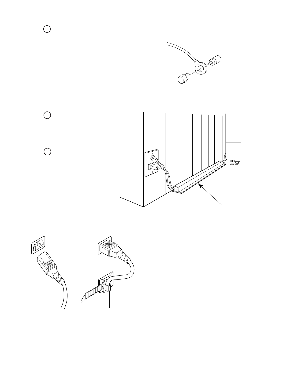
Connect one end of the earth wire to the
2
AC Unit earth terminal, and the other end
to the indoor earth terminal. The AC
Unit earth terminal has a Bolt and Nut
combination. Take off the Nut, pass the
earth wire through the Bolt, and fasten
the Nut.
Note that the Earth Wire is incorporated
in the Power Cord for the Areas of AC
120V (USA) and AC 220 ~ 240V, and
therefore, this procedure is not necessary.
Firmly insert the power plug into the
3
socket outlet.
Insert the opposite side of Power Cord
plug to the AC Unit's connector
("INLET").
4
Perform wiring for the Power Cord
and Earth Wire. Install protective
covering for the Power Cord and
Earth Wire.
Connect the Earth Wire
to the Earth Terminal.
FIG. 6. 5 b Earth Wire Connection
HOW TO USE THE CORD CLAMP
Wiring Cover
FIG. 6. 5 c Connecting Power Cord and Earth Wire
In case the Power Plug is apt to come out of place, secure the
Power Cord to the periphery of the AC Unit with the Cord
Clamp (an accessory).
www.seuservice.com
20
Page 27
TURNING POWER ON
6
Turning the AC UNIT's MAIN SW on will cause the machine to start the POWER ON check
and GAME BOARD SYSTEM check automatically.
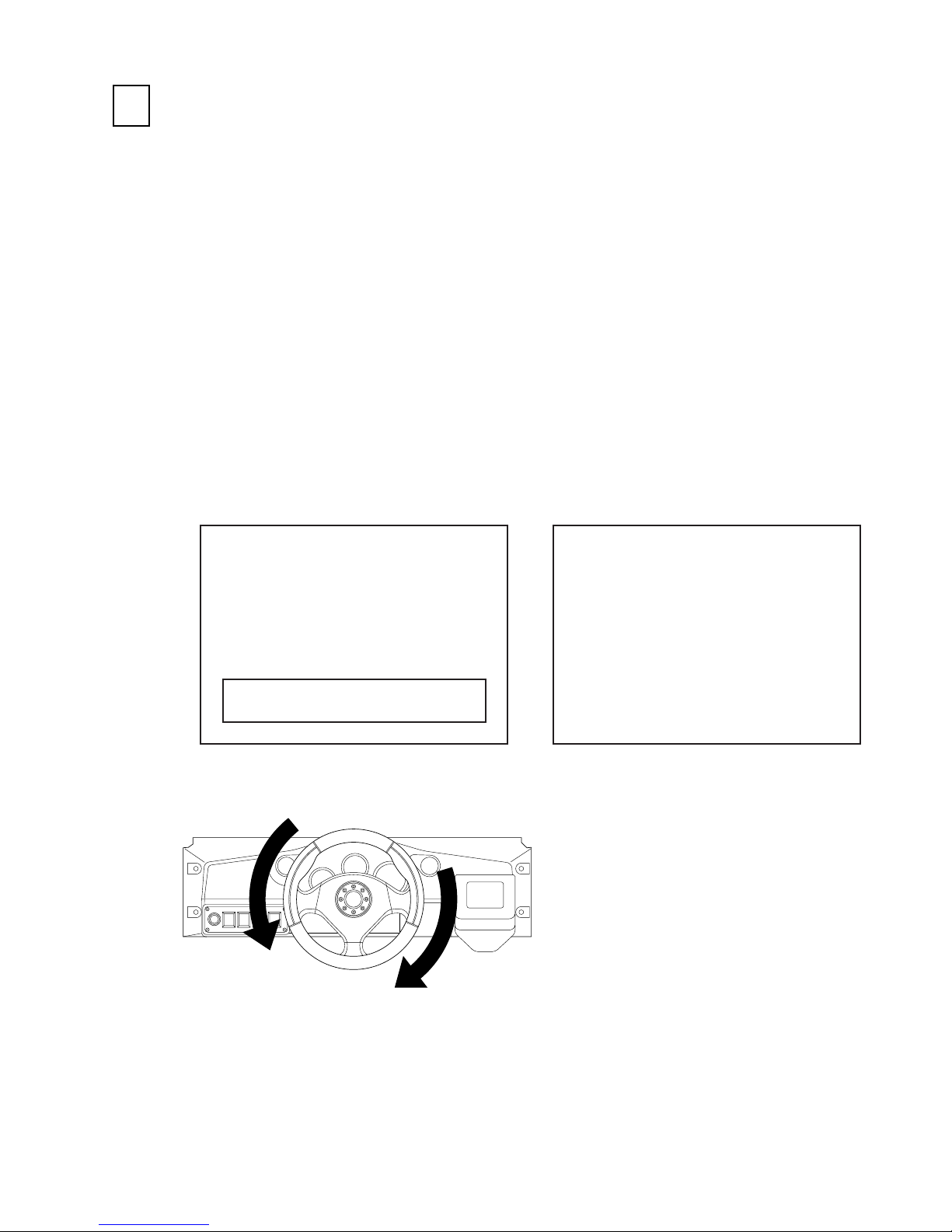
In the POWER ON check, the steering wheel turns left and right, then returns to the centering
position and stops. In this check, the values of V. R. inside the control panel are corrected.
Until the check is finished (the steering wheel stops automatically), do not touch the steering
wheel or play the game.
If you do, the steering wheel reaction during the game (reaction at the time of a course-out or
crashing) can not be obtained correctly.
In a case of an abnormal reaction during the game, turn the power on again from the beginning
and complete the power-on check.
Note that turning power on when the Steering Wheel is fully turned right or left may sometimes
not allow for performing power on check satisfactorily. Ensure the Steering Wheel is in the
centering position, and then turn on power.
During game board system checking, the check mode will appear on the monitor. After one
minute, the screen proceeds to the network check.
During network checking, "CHECKING NETWORK NOW" is displayed on the screen. When
the network checking is finished, the DEMO mode will appear on the monitor screen.
After 30 seconds, if the network check is not finished, check connections for Communication.
MODE : MASTER
naomi multi system.
The steering wheel turns left/right automatically.
CHECKING NETWORK NOW
NETWORK CHECK SCREENGAME BOARD SYSTEM CHECK SCREEN
FIG. 6. 6
21
www.seuservice.com
Page 28
ASSEMBLING CHECK
7
In the TEST MODE, ascertain that the assembly has been made correctly and IC BD. is
satisfactory (refer to Section 9).
In the test mode, perform the following test:
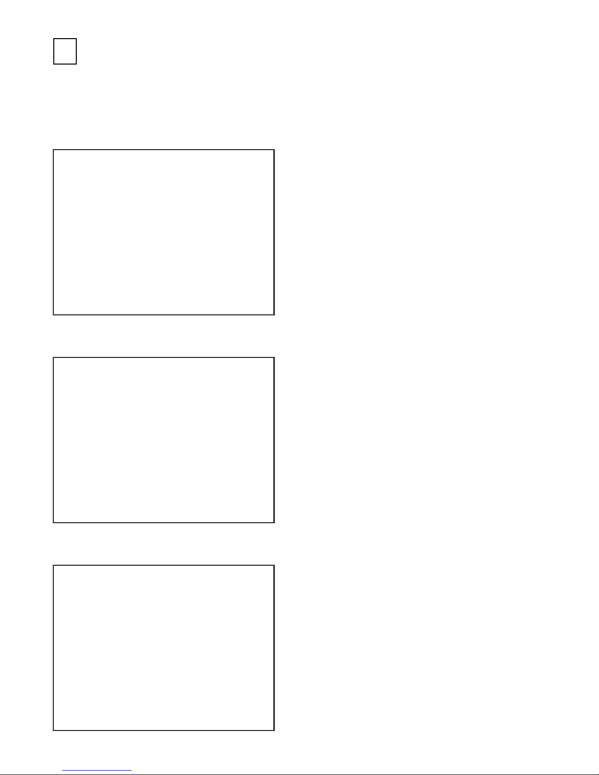
(1) MEMORY TEST
RAM TEST
IC29 GOOD
IC35 GOOD
IC16 GOOD IC18 GOOD
IC20 GOOD IC22 GOOD
IC09 GOOD IC10 GOOD
IC11 GOOD IC12 GOOD
PRESS TEST BUTTON TO EXIT
(2) INPUT TEST
Å° INPUT TEST Å°
- SYSTEM SWITCH CHUTE #1 OFF CHUTE #2 OFF
TEST OFF B TEST OFF
SERVICE OFF B SERVICE OFF
- GAME SWITCH START OFF
SC OFF TC OFF
ABS OFF IBS OFF
- WING SHIFT WING L ON WING R OFF
- ANALOG DEVICE HANDLE 7B H ACCEL 2E H
BRAKE 2F H
- OTHER DEVICE VISUAL MEMORY UNCONNECTED
Selecting the RAM TEST on the system test mode
menu screen causes the on-board memory to be tested
automatically. The game board is satisfactory if the
display beside each IC No. shows GOOD.
Selecting the INPUT TEST on the game test mode
menu screen causes the screen (on which each switch
and V.R. are tested) to be displayed. Press each
switch. For the coin switch test, insert a coin from the
coin inlet with the coin chute door open. If the
display beside each switch indicates "ON," the switch
and wiring connections are satisfactory.
Check the display of V. R. value for the steering
wheel and accelerator & brake. If the V. R. values are
not satisfactory, refer to Sections 10 & 11.
PRESS SERVICE + TEST BUTTON TO EXIT
(3) OUTPUT TEST
Å° OUTPUT TEST MENU Å°
LAMP TEST
DRIVE BOARD TEST
-> EXIT TO SYSTEM TEST MODE
SELECT WITH SERVICE BUTTON
AND PRESS TEST BUTTON
www.seuservice.com
The OUTPUT TEST menu screen in the game test
mode allows Lamp and Motor to be checked. Check
if Lamp and Motor are satisfactory.
22
Page 29
3
3
3
3
3
3
3
3
3
3
3
3
3
3
3
3
3
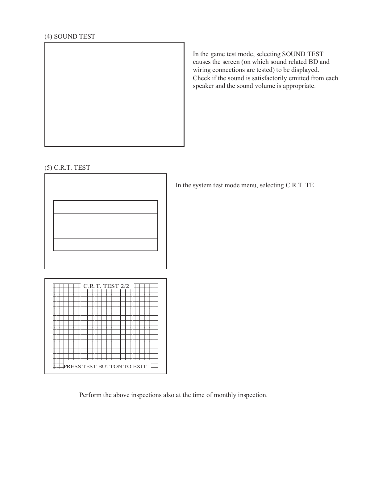
(4) SOUND TEST
Å° SOUND TEST Å°
TITLE '-------'
MUSIC STOP
MUSIC FADEOUT
SE-M0 No.0
SE-M1 No.0
SE-M2 No.0
SE-S0 No.0
-> EXIT
SELECT WITH SERVICE BUTTON
AND PRESS TEST BUTTON
(5) C.R.T. TEST
C.R.T. TEST 1/2
1 32
RED
GREEN
BLUE
WHITE
PRESS TEST BUTTON TO CONTINUE
In the game test mode, selecting SOUND TEST
causes the screen (on which sound related BD and
wiring connections are tested) to be displayed.
Check if the sound is satisfactorily emitted from each
speaker and the sound volume is appropriate.
In the system test mode menu, selecting C.R.T. TEST allows
the screen (on which the monitor is tested) to be displayed.
Although the monitor adjustments have been made at the
time of shipment from the factory, color deviation, etc., may
occur due to the effect caused by geomagnetism, the location
building's steel frames and other game machines in the
periphery. By watching the test mode screen, make
judgment as to whether an adjustment is needed. If it is
necessary, adjust the monitor by referring to Section 14.
Use the DEMAG SW to remove color deviation due to
magnetization. (see Sec. 9)
234567890123456789012
C.R.T. TEST 2/2
234567890123456789012
234567890123456789012
234567890123456789012
234567890123456789012
234567890123456789012
234567890123456789012
234567890123456789012
234567890123456789012
234567890123456789012
234567890123456789012
234567890123456789012
234567890123456789012
234567890123456789012
234567890123456789012
234567890123456789012
234567890123456789012
PRESS TEST BUTTON TO EXIT
Perform the above inspections also at the time of monthly inspection.
23
www.seuservice.com
Page 30
7.
PRECAUTIONS TO BE HEEDED WHEN MOVING THE MACHINE
When moving the machine, be sure to unplug the power plug. Moving the
machine with the plug as is inserted can damage the power cord, and cause
fire and electric shock hazards.
When moving the machine on the floor, retract the Adjusters and ensure that
Casters make contact with the floor. During transportation, pay careful
attention so that Casters do not tread power cords and earth wires. Damaging
the power cords can cause electric shock and short circuit hazards.
When moving the machine, do not push the cabinet from the left/right
direction. Pushing the cabinet from the left/right direction can cause the
cabinet to fall down, resulting in injury and or parts damage.
Do not push glass parts (CRT, etc.) or plastic parts. Failure to observe this may
damage parts and cause injury due to an accident or fragments resulting from
damage.
STOP
When transporting the product in places with steps, disassemble into each unit
before transporting. Inclining the product in an as is assembled condition or
placing the cabinet in places with steps can damage the unit's joining portions.
IMPORTANT!
When transporting the product in places with steps or steplike differences in grade, disassemble into each unit before
transporting.
www.seuservice.com
FIG. 7 a
24
Page 31

Do not push an
independent
(detached)
cockpit from the
left/right
direction.
FIG. 7 b
Have casters make contact with the floor.
FIG. 7 c
25
www.seuservice.com
Page 32

8. CONTENTS OF GAME
The following explanations apply to the case the product is functioning satisfactorily. Should
there be any moves different from the following contents, some sort of faults may have occurred.
Immediately look into the cause of the fault and eliminate the cause thereof to ensure satisfactory
operation.
STEERING WHEEL
PADDLE SHIFT
START BUTTON
ASSIST FUNCTION BUTTONS
BRAKE PEDAL
From GAME START up to the end of SELECT
Insert a credit worth number of coins. Inserting one play worth of coins causes the Start button
to flash. When the Start button is pressed, the credit is consumed. In case the credit is less than
one play worth, the Start button goes off.
ACCEL. PEDAL
www.seuservice.com
26
Page 33

• In case of single play >
Select Game Contents
1) Select the course from
among the 6 courses in
the Course Select screen.
2) Select the level from the
2 levels in the Level
Select screen.
Turn the Steering Wheel left and right to choose and decide the
selection by stepping on the Accelerator Pedal.
27
www.seuservice.com
Page 34

The following levels are available in single play.
About Assist Functions
NOVICE • Automatic
•All Assist functions are offered.
INTERMEDIATE • Semi-Automatic (Paddle-shift)
•All Assist functions except IBS
are offered.
SC
Stability Control
Stabilizes and controls position
of the car in a cornering.
TC
Traction Control
Controls the powertrain in a wheelspin,
and stabilizes the control of the car.
ABS
Anti-lock Brake System
Prevents your tires from locking
when you brake.
IBS
Intelligent Brake System
Automatic braking before a curve.
Each Assist Function can be turned ON
and OFF while driving.
www.seuservice.com
28
Page 35

3) Select the mode from
among the 3 modes in the
Mode Select screen.
The following game modes are available in single play.
TRAINING MODE:
DRIVING MODE:
RACE MODE:
*Additional 100 seconds per one credit is added when continued.
The course is navigated by the screen displays & voices and suitable
for beginners to learn how to drive, the characteristics of the car, and
to remember the course. In this mode, finishing the predetermined
laps within the time limit to goal results in a game over.
This mode is single run in the circuit and is suitable for the player to
brash up his driving technique. No navigation is available. In this
mode, the game is over when the time is up and can be continued by
inserting additional coins.
This mode is suitable for the player who wishes to experiment in
driving technique in the practical race. In this mode, finishing the
predetermined raps within the time limit to goal results in a game
over.
29
www.seuservice.com
Page 36

< In case of communication play >
Press START button during the entry acceptance to enter the Communication Play mode.
Select Game Contents
1) Select the course from among the 6 courses in the Course Select screen.
www.seuservice.com
30
Page 37

During the Communication Play, the following communication conditions are available. Setting of the communication conditions can be changed in the GAME TEST mode.
HEAT : An exciting, nip-and tuck race from the game start to the end.
AID : By taking advantage of the Assist Functions, the NOVICE (AT) player can run the
advanced player close.
PRO : Offers a hotly contested game under the equal condition among all cars.
2) Select the level from among 3 levels in the Level Select screen.
< In case of HEAT >
NOVICE • Automatic
INTERMEDIATE • Semi-Automatic (Paddle-shift)
PROFESSIONAL • Semi-Automatic (Paddle-shift)
•All Assist functions are offered.
•All Assist functions except IBS are offered.
•All Assist functions except IBS are offered.
•In this mode, Handicap is not given.
31
www.seuservice.com
Page 38

< In case of AID or PRO >
In case of AID
NOVICE • Automatic
•All Assist functions are offered.
INTERMEDIATE • Semi-Automatic (Paddle-shift)
•All Assist functions except IBS are offered.
•In this mode, Handicap is not given.
In case of PRO
NOVICE • Automatic
•All Assist functions are offered.
•In this mode, Handicap is not given.
INTERMEDIATE • Semi-Automatic (Paddle-shift)
•All Assist functions except IBS are offered.
•In this mode, Handicap is not given.
www.seuservice.com
32
Page 39

9. EXPLANATION OF TEST AND DATA DISPLAY
By operating the switch unit, periodically perform the tests and data check. When installing the
machine initially or collecting cash, or when the machine does not function correctly, perform
checking in accordance with the explanations given in this section.
The following shows tests and modes that should be utilized as applicable.
NAOMI GAME BOARD is used for the product. The Test Mode of this system consists of the
System Test Mode for the system to execute SELF-TEST, COIN ASSIGNMENTS, etc. used in
common for the machines employing the NAOMI BOARD, and the Game Test Mode for the
specific product to execute Input/Output test for the operation equipment, difficulty setting, etc.
TABLE 9 EXPLANATION OF TEST MODE
ITEMS DESCRIPTION
REFERENCE
SECTIONS
INSTALLATION
OF MACHINE
MEMORY
PERIODIC
SERVICING
CONTROL
SYSTEM
MONITOR
When the machine is installed, perform the following:
1. Check to ensure each is the standard setting at shipment.
2. Check each Input equipment in the INPUT TEST mode.
3. Check each Output equipment in the OUTPUT TEST mode.
4. Test on-IC-Board IC's in the SELF-TEST mode.
This test is automatically executed by selecting RAM TEST, or
ROM BOARD TEST in the Menu mode.
Periodically perform the following:
1. MEMORY TEST
2. Ascertain each setting.
3. To test each Input equipment in the INPUT TEST mode.
4. To test each Output equipment in the OUTPUT TEST mode.
1. To check each Input equipment in the INPUT TEST mode.
2. Adjust or replace each Input equipment.
3. If the problem still remains unsolved, check each equipment's
mechanism movements.
In the Monitor Adjustment mode, check to see if Monitor (Projector) adjustments are appropriate.
9 - 2
9 - 3A
9 - 2/2, 9 - 3D
9 - 3 F, G
9 - 2/1, 9 - 2/10
9 - 2/1, 9 - 2/10
9 - 2/1, 9 - 2/10
9 - 2/2, 9 - 3 A
9 - 3 A
9 - 3 B
9 - 2/2, 9 - 3 A
10, 11, 12
9 - 3 E
9 - 2/4
14
IC BOARD
1. MEMORY TEST
2. In the SOUND TEST mode, check the sound related ROMs.
DATA CHECK
Check such data as game play time and histogram to adjust the
difficulty level, etc.
33
9 - 2/1, 9 - 2/10
9 - 3 C
9 - 2/7
9 - 3 E
www.seuservice.com
Page 40

9 - 1 SWITCH UNIT AND COIN METER
Never touch places other than those specified. Touching places not specified can
cause electric shock and short circuit accidents.
STOP
Adjust to the optimum sound volume by considering the environmental
requirements of the installation location.
If the COIN METER and the game board are electrically disconnected, game
IMPORTANT!
SWITCH UNIT
Open the coin chute door, and the
switch unit shown will appear. The
function of each SW is as follows:
play is not possible.
SWITCHES FOR THE
LEFT SIDE PLAYER
SWITCHES FOR THE
RIGHT SIDE PLAYER
Sound Volume for left/right
Speakers (Seat Backrest)
SPEAKER
Sound Volume for woofer.
WOOFER
WOOFERSPEAKER
LEFT PLAYER
TEST
RIGHT PLAYER
FIG. 9. 1 a SWITCH UNIT
DEMAG.SERVICE
421-9482
TEST BUTTON: For the handling of the test button, refer to the following pages.
TEST
SERVICE BUTTON: Gives credits without registering on the coin meter.
SERVICE
DEMAGNETIZER BUTTON: Eliminates the on-screen color unevenness due to magnetization of
DEMAG
CRT. First use this SW before performing the monitor's color
adjustment.
COIN METER
Open the Cashbox Door by using the key
to have the Coin Meter appear
underneath the Cashbox.
COIN METER1 (Left side)
Counts the number of coins
into 1P side.
FIG. 9. 1 b COIN METER
COIN METER2 (Right side)
Counts the number of coins
into 2P side.
www.seuservice.com
34
Page 41
9 - 2 SYSTEM TEST MODE
STOP
The contents of setting changes in SYSTEM ASSIGNMENTS, COIN
ASSIGNMENTS, and GAME TEST MODE are stored when the test mode is
EXITed. If the power is turned off before EXITing, the contents of setting
IMPORTANT!
TEST ITEM SELECT
1) After turning power on, press the TEST button to have the following test item menu displayed.
changes are ineffective. Be very careful of this point.
This test mode mainly allows the IC Board to be checked for accurate functioning, monitor
color to be adjusted as well as COIN ASSIGNMENTS and GAME ASSIGNMENTS to be
adjusted.
Although the menu is displayed on all of the 3 monitors (front, left and right), perform work by
watching the front monitor only.
SYSTEM MENU
XXXXX VERSION
RAM TEST
JVS TEST
SOUND TEST
C.R.T. TEST
SYSTEM ASSIGNMENTS
COIN ASSIGNMENTS
BOOKKEEPING
BACKUP DATA CLEAR
CLOCK SETTING
ROM BOARD TEST
GAME TEST MODE
[XXXXX XXXXX XXXXX XXXXX]
-> EXIT
SELECT WITH SERVICE BUTTON
AND
PRESS TEST BUTTON
2) Press the SERVICE button to move the arrow. Bring the arrow to the desired item and press the
TEST button.
3) Upon finishing the test, bring the arrow to EXIT and press the TEST button to return to the
Game mode.
35
www.seuservice.com
Page 42

RAM TEST
1
This allows for checking the functioning of the RAM on the NAOMI Main BD.
"GOOD" is displayed for satisfactory RAMs, and "BAD" is indicated for irregular RAMs, if
any.
RAM TEST
IC29 GOOD
IC35 GOOD
IC16 GOOD IC18 GOOD
IC20 GOOD IC22 GOOD
IC09 GOOD IC10 GOOD
IC11 GOOD IC12 GOOD
PRESS TEST BUTTON TO EXIT
During test, "TESTING NOW" is displayed.
Press the TEST button to return to the menu mode.
www.seuservice.com
36
Page 43

JVS TEST
2
In this test, Specifications of the I/O Board connected to NAOMI can be checked, and INPUT
TEST can be performed. First, I/O Board Specifications are displayed.
JVS TEST
INPUT TEST (A)
NEXT NODE (B)
-> EXIT (C)
NODE 1/1
NAME SEGA ENTERPRISES,LTD.
837-13741 I/O CONTROL BD
Ver0.15
99/06
CMD VER 1.1
JVS VER 2.0
COM VER 1.0
SWITCH 2PLAYER(S) 12BITS
COIN 2SLOT
ANALOG 8CH
ROTARY 0CH
KEYCODE 0
SCREEN X:0 Y:0 CH:0
CARD OSLOT
HOPPER OUT 0CH
DRIVER OUT 22 SLOT
ANALOG OUT 0 CH
CHARACTER CHARA:0 LINE:0
BACKUP 0
SELECT WITH SERVICE BUTTON
AND
PRESS TEST BUTTON
Select with the SERVICE button and press the TEST button.
(A) INPUT TEST : Proceeds to the INPUT TEST of I/O BOARD being displayed.
(B) NEXT NODE : In the case where more than 2 I/O Boards are connected, proceeds to
(C) EXIT : Returns to the menu mode.
INPUT TEST SCREEN
JVS TEST
INPUT TEST
NEXT NODE
-> EXIT
NODE 1/1
SWITCH
SYSTEM 00000000
PLAYER1 00000000
00000000
PLAYER2 00000000
00000000
COIN
0000 0000
ANALOG
0000 0000 0000 0000
0000 0000 0000 0000
SELECT WITH SERVICE BUTTON
AND
PRESS TEST BUTTON
the next I/O Board. Note that it does not function in this product.
When INPUT is performed for the switches
of Control Panel, etc., the value changes to
1 from 0.
If the Coin SW is inputted, the value
momentarily changes to 1 from 0.
The Coin Meter counts.
Analogue values are displayed between
0000 and FF00.
37
www.seuservice.com
Page 44

3
3
3
3
3
3
3
3
3
3
3
3
3
3
3
3
3
SOUND TEST
3
Sound Output test can be performed. Beep sounds can be emitted from each of left/right Speakers.
SOUND TEST
C.R.T. TEST
4
A) RGB COLOR ADJUSTMENT SCREEN
In this page, monitor color can be checked.
RIGHT SPEAKER OFF
LEFT SPEAKER OFF
-> EXIT
SELECT WITH SERVICE BUTTON
AND
PRESS TEST BUTTON
C.R.T. TEST 1/2
1 32
RED
GREEN
BLUE
WHITE
fEmitted from the right-hand side Speaker.
fEmitted from the left-hand side Speaker.
fReturns to the menu mode.
Each of red, green, and blue is the darkest at the
leftmost end, and becomes brighter towards the
right-hand end in 31 gradations. Monitor
brightness is satisfactory if the white color bar
is black at the left end and if it is white at the
right end.
Press the TEST button to proceed to the next
page.
PRESS TEST BUTTON TO CONTINUE
B) MONITOR SIZE ADJUSTMENT SCREEN
In this page, monitor size can be checked.
C.R.T. TEST 2/2
234567890123456789012
234567890123456789012
234567890123456789012
234567890123456789012
234567890123456789012
234567890123456789012
234567890123456789012
234567890123456789012
234567890123456789012
234567890123456789012
234567890123456789012
234567890123456789012
234567890123456789012
234567890123456789012
234567890123456789012
234567890123456789012
234567890123456789012
www.seuservice.com
PRESS TEST BUTTON TO EXIT
Adjust so that the checkered patterns do not go
beyond the screen.
Press the TEST button to return to the menu
mode.
38
Page 45

SYSTEM ASSIGNMENTS
5
STOP
If the settings of CABINET TYPE and MONITOR TYPE are not suitable for the
connected game, Error Message is displayed after turning power on and upon
finishing the TEST mode, and in this case, game is not playable.
IMPORTANT!
The setting of cabinet and board can be changed. Game related assignments such as game
difficulty, etc. are performed in 2-3 GAME TEST MODE.
1) Press the SERVICE button to move the arrow. Bring the arrow to the desired item.
2) Press the TEST button to change the setting.
3) Upon finishing the setting, move the arrow to EXIT and press the TEST button.
SYSTEM ASSIGNMENTS
CABINET TYPE 1PLAYER(S) (A)
ADVERTISE SOUND ON (B)
MONITOR TYPE HORIZONTAL (C)
SERVICE TYPE COMMON (D)
-> EXIT
SELECT WITH SERVICE BUTTON
AND
PRESS TEST BUTTON
(A) CABINET TYPE (1PLAYER(S), 2PLAYER(S), 3PLAYER(S), 4PLAYER(S))
Sets number of players between 1 and 4. Set to 1 PLAYER(S).
(B) ADVERTISE SOUND (ON, OFF)
Sets whether ADVERTISE sound is to be emitted or not. Normally, set to ON.
(C) MONITOR TYPE (HORIZONTAL, VERTICAL)
Fix setting to HORIZONTAL.
(D) SERVICE TYPE (COMMON, INDIVIDUAL)
Set to COMMON.
39
www.seuservice.com
Page 46

COIN ASSIGNMENTS
6
In this mode, the setting of incremental credit increase as against coin insertion can be changed.
1) Press the SERVICE button to move the arrow. Bring the arrow to the desired item.
2) Press the TEST button to change the setting.
3) Upon finishing the setting, bring the arrow to EXIT and press the TEST button.
COIN ASSIGNMENTS
COIN CHUTE TYPE COMMON (A)
COIN/CREDIT SETTING #1 (B)
COIN CHUTE #1
1 COIN 1 CREDIT
COIN CHUTE #2
1 COIN 1 CREDIT
MANUAL SETTING (C)
SEQUENCE SETTING (G)
->EXIT
SELECT WITH SERVICE BUTTON
AND
PRESS TEST BUTTON
(COMMON SETTING)
(A) COIN CHUTE TYPE (COMMON, INDIVIDUAL)
Set to COMMON.
Up to 2 Coin Chutes (#1 and #2) can be used and also, (B) COIN/CREDIT SETTING ratio can
be set separately for #1 and #2.
(B) COIN/CREDIT SETTING (#1 ~ #27)
Sets the credit increase increment per coin insertion. There are 27 settings from #1 to #27,
expressed in OO credit(s) as against OO coins inserted. #27 refers to FREE PLAY.
For details, refer to Table 1 (COMMON).
www.seuservice.com
40
Page 47

(C) MANUAL SETTING
The Credit's incremental increase settings as against a coin insertion are shown in further details
than in (B) above (refer to Table 3). Also, note that when this MANUAL SETTING is
performed, (B) COIN CREDIT setting becomes ineffective.
COIN ASSIGNMENTS
MANUAL SETTING
COIN TO CREDIT 1 (D)
BONUS ADDER NO BONUS ADDER (E)
COIN CHUTE #1 MULTIPLIER (F)
1 COIN COUNT AS 1 COIN
COIN 1 2 3 4 5 6 7 8 9
CREDIT 1 2 3 4 5 6 7 8 9
COIN CHUTE #2 MULTIPLIER (F)
1 COIN COUNT AS 1 COIN
COIN 1 2 3 4 5 6 7 8 9
CREDIT 1 2 3 4 5 6 7 8 9
SEQUENCE SETTING (G)
MANUAL SETTING
->EXIT
SELECT WITH SERVICE BUTTON
AND
PRESS TEST BUTTON
(D) COIN TO CREDIT
Determines COIN/CREDIT setting.
(E) BONUS ADDER
This sets how many coins should be inserted to obtain one SERVICE COIN.
(F) COIN CHUTE (#1 / #2) MULTIPLIER
This sets how many tokens one coin represents.
41
www.seuservice.com
Page 48

Table 1: COIN/CREDIT SETTING (COIN CHUTE COMMON TYPE)
NAME OF SETTING COIN CHUTE 1 COIN CHUTE 2
SETTING #1 1 COIN 1 CREDIT 1 COIN 1 CREDIT
SETTING #2 1 COIN 2 CREDITS 1 COIN 1 CREDIT
SETTING #3 1 COIN 3 CREDITS 1 COIN 1 CREDIT
SETTING #4 1 COIN 4 CREDITS 1 COIN 1 CREDIT
SETTING #5 1 COIN 5 CREDITS 1 COIN 1 CREDIT
SETTING #6 1 COIN 2 CREDITS 1 COIN 2 CREDITS
SETTING #7 1 COIN 5 CREDITS 1 COIN 2 CREDITS
SETTING #8 1 COIN 3 CREDITS 1 COIN 3 CREDITS
SETTING #9 1 COIN 4 CREDITS 1 COIN 4 CREDITS
SETTING #10 1 COIN 5 CREDITS 1 COIN 5 CREDITS
SETTING #11 1 COIN 6 CREDITS 1 COIN 6 CREDITS
SETTING #12 2 COINS 1 CREDIT 2 COINS 1 CREDIT
SETTING #13 1 COIN 1 CREDIT 2 COINS 1 CREDIT
SETTING #14 1 COIN 2 CREDITS 2 COINS 1 CREDIT
SETTING #15 1 COIN 1 CREDIT 1 COIN 1 CREDIT
2 COINS 3 CREDITS 2 COINS 3 CREDITS
SETTING #16 1 COIN 3 CREDITS 1 COIN 1 CREDIT
SETTING #17 3 COINS 1 CREDIT 3 COINS 1 CREDIT
SETTING #18 4 COINS 1 CREDIT 4 COINS 1 CREDIT
SETTING #19 1 COIN 1 CREDIT 1 COIN 1 CREDIT
2 COINS 2 CREDITS 2 COINS 2 CREDITS
3 COINS 3 CREDITS 3 COINS 3 CREDITS
4 COINS 5 CREDITS 4 COINS 5 CREDITS
SETTING #20 1 COIN 5 CREDITS 1 COIN 1 CREDIT
SETTING #21 5 COINS 1 CREDIT 5 COINS 1 CREDIT
SETTING #22 1 COIN 2 CREDITS 3 COINS 1 CREDIT
SETTING #23 2 COINS 1 CREDIT 2 COINS 1 CREDIT
4 COINS 2 CREDITS 4 COINS 2 CREDITS
5 COINS 3 CREDITS 5 COINS 3 CREDITS
SETTING #24 1 COIN 3 CREDITS 2 COINS 1 CREDIT
SETTING #25 1 COIN 1 CREDIT 1 COIN 1 CREDIT
2 COINS 2 CREDITS 2 COINS 2 CREDITS
3 COINS 3 CREDITS 3 COINS 3 CREDITS
4 COINS 4 CREDITS 4 COINS 4 CREDITS
5 COINS 6 CREDITS 5 COINS 6 CREDITS
SETTING #26 1 COIN 6 CREDITS 1 COIN 1 CREDIT
SETTING #27 FREE PLAY FREE PLAY
2 COINS 3 CREDITS
2 COINS 2 CREDITS
3 COINS 3 CREDITS
4 COINS 5 CREDITS
5 COINS 2 CREDITS
4 COINS 2 CREDITS
5 COINS 3 CREDITS
2 COINS 2 CREDITS
3 COINS 3 CREDITS
4 COINS 4 CREDITS
5 COINS 6 CREDITS
www.seuservice.com
42
Page 49

Table 2: MANUAL SETTING
C O I N TO C R E D I T 1 COIN 1 CREDIT
2 COIN 1 CREDIT
3 COIN 1 CREDIT
4 COIN 1 CREDIT
5 COIN 1 CREDIT
6 COIN 1 CREDIT
7 COIN 1 CREDIT
8 COIN 1 CREDIT
9 COIN 1 CREDIT
B O N U S A D D E R N O B O N U S A D D E R
2 COINS GIVE 1 EXTRA COIN
3 COINS GIVE 1 EXTRA COIN
4 COINS GIVE 1 EXTRA COIN
5 COINS GIVE 1 EXTRA COIN
6 COINS GIVE 1 EXTRA COIN
7 COINS GIVE 1 EXTRA COIN
8 COINS GIVE 1 EXTRA COIN
9 COINS GIVE 1 EXTRA COIN
C O I N C H U T E ( # 1 / # 2 ) 1 COINS COUNTS AS 1 COIN
M U L T I P L I E R 1 COINS COUNTS AS 1 COIN
1 COINS COUNTS AS 1 COIN
1 COINS COUNTS AS 1 COIN
1 COINS COUNTS AS 1 COIN
1 COINS COUNTS AS 1 COIN
1 COINS COUNTS AS 1 COIN
1 COINS COUNTS AS 1 COIN
1 COINS COUNTS AS 1 COIN
43
www.seuservice.com
Page 50

(G) SEQUENCE SETTING
Number of credits required for starting game, etc. can be set.
Each sequence can be set between 1Å`5 credit(s).
COIN ASSIGNMENTS
SEQUENCE SETTING
SEQUENCE 1 2 CREDIT(S)
SEQUENCE 2 1 CREDIT(S)
SEQUENCE 3 1 CREDIT(S)
SEQUENCE 4 1 CREDIT(S)
SEQUENCE 5 1 CREDIT(S)
SEQUENCE 6 1 CREDIT(S)
SEQUENCE 7 1 CREDIT(S)
SEQUENCE 8 1 CREDIT(S)
-> EXIT
[XXXXX XXXXX XXXXX XXXXX]
DESCRIPTION OF SEQUENCE
1 CREDIT TO START
2 CREDIT TO CONTINUE
3 CREDIT TO PRINTOUT
4 NO USE
5 NO USE
6 NO USE
7 NO USE
8 NO USE
SELECT WITH SERVICE BUTTON
AND PRESS TEST BUTTON
SEQUENCE 1 : Number of credits required for game start.
SEQUENCE 2 : Number of credits required for CONTINUE.
SEQUENCE 3 ~ 8 : NOT USED.
www.seuservice.com
44
Page 51

BOOKKEEPING
7
• BOOKKEEPING 1/2
This allows such data as operating time/No. of coins inserted/ No. of credits to be checked.
Perform work by watching the front monitor only.
BOOKKEEPING 1/2
TOTAL TIME
0D 00H 00M 00S
CREDIT 0
COIN 1 0
COIN 2 0
COIN 3 0
COIN 4 0
TOTAL COIN 0
COIN CREDIT 0
SERVICE CREDIT 0
TOTAL CREDIT 0
PRESS TEST BUTTON TO CONTINUE
Press the TEST button to proceed to BOOKKEEPING 2/2.
• BOOKKEEPING 2/2
Each sequence displays the frequency of functioning.
BOOKKEEPING 2/2
P1 SEQ 1 0
P1 SEQ 2 0
P1 SEQ 3 0
P1 SEQ 4 0
P1 SEQ 5 0
P1 SEQ 6 0
P1 SEQ 7 0
P1 SEQ 8 0
PRESS TEST BUTTON TO EXIT
P1 SEQ 1 : Frequency of Game Start by the player.
P1 SEQ 2 : Frequency of CONTINUE by Player (Player 2)
P1 SEQ 3 ~ 8 : NOT USED.
45
www.seuservice.com
Page 52

BACKUP DATA CLEAR
8
Clears the contents of BOOKKEEPING (SYSTEM TEST MODE).
The data regarding the coins, the credits, and the total time in the BOOKKEEPING in the GAME
TEST Mode are also cleared.
BACKUP DATA CLEAR
YES(CLEAR)
-> NO(CANCEL)
SELECT WITH SERVICE BUTTON
AND
PRESS TEST BUTTON
When clearing, bring the arrow to YES by using the SERVICE button and press the TEST
button. Bring the arrow to NO and press the TEST button to have the menu mode return
without clearing the data. COMPLETED is displayed when clearing is completed. Press the
TEST button to return to the menu mode.
9
CLOCK SETTING
Set YEAR, MONTH, DAY, HOUR, and MINUTE for NAOMI Main BD.
Select the desired item with the SERVICE button and press the TEST button to increase the
value. Upon finishing the SETTING, bring the arrow to EXIT and press the TEST button to
return to the menu mode.
CLOCK SETTING
1998 12/02 14:30 33 WED
YEAR 1998 ~ 2030
MONTH
DAY
HOUR
MINUTE
-> EXIT
SELECT WITH SERVICE BUTTON
AND
PRESS TEST BUTTON
www.seuservice.com
46
Page 53

ROM BOARD TEST
10
In this test, on-ROM-BD ROM check is executed. If GOOD is displayed, it is satisfactory.
However, Program ROMs (IC22) do not display GOOD or BAD.
BYTE and WORD refers to the check sum of each unit.
ROM BOARD TEST
[XXXXX XXXXX XXXXX]
NO. TYPE RESULT BYTE WORD
IC22 32M ---- XXXX XXXX
IC1 64M GOOD XXXX XXXX
IC2 64M GOOD XXXX XXXX
IC3 64M GOOD XXXX XXXX
IC4 64M GOOD XXXX XXXX
IC5 64M GOOD XXXX XXXX
IC6 64M GOOD XXXX XXXX
IC7 64M GOOD XXXX XXXX
IC8 64M GOOD XXXX XXXX
IC9 64M GOOD XXXX XXXX
IC10 64M GOOD XXXX XXXX
IC11 64M GOOD XXXX XXXX
• • • • •
• • • • •
IC21 64M GOOD XXXX XXXX
PRESS TEST BUTTON TO EXIT
Press the TEST button to return to the menu mode.
47
www.seuservice.com
Page 54

9 - 3 GAME TEST MODE
Press TEST Button to display the SYSTEM TEST MODE MENU.
SYSTEM MENU
XXXXX VERSION
RAM TEST
JVS TEST
SOUND TEST
C.R.T. TEST
SYSTEM ASSIGNMENTS
COIN ASSIGNMENTS
BOOKKEEPING
BACKUP DATA CLEAR
CLOCK SETTING
ROM BOARD TEST
GAME TEST MODE
[F355 CHALLENGE XXXXX]
-> EXIT
SELECT WITH SERVICE BUTTON
AND
PRESS TEST BUTTON
• By pressing SERVICE Button, move the arrow (->) to select the GAME TEST MODE.
Press TEST Button to enter GAME TEST MODE.
• The screen displays the GAME TEST MODE MENU.
F355 Challenge APPLICATION TEST MENU
INPUT TEST
OUTPUT TEST
SOUND TEST
GAME ASSIGNMENTS
BOOKKEEPING
F355 BACKUP DATA CLEAR
-> EXIT TO SYSTEM TEST MODE
SELECT WITH SERVICE BUTTON
AND PRESS TESS BUTTON
• By pressing SERVICE Button, move the arrow (->) to select the desired item and press TEST
Button to execute the selected item. Use the same procedure for selecting/executing the item in
the following GAME TEST MODE.
• Select EXIT and press TEST Button to exit from the GAME TEST MODE and return to the
SYSTEM TEST MODE MENU. Further, select EXIT and press TEST Button to finish
SYSTEM TEST MODE and return to the normal mode.
www.seuservice.com
48
Page 55

A) INPUT TEST
Selecting INPUT TEST displays the following screen on the monitor.
INPUT TEST
- SYSTEM SWITCH CHUTE #1 OFF CHUTE #2 OFF
TEST OFF B TEST OFF
SERVICE OFF B SERVICE OFF
- GAME SWITCH START OFF
SC OFF TC OFF
ABS OFF IBS OFF
- WING SHIFT WING L ON WING R OFF
- ANALOG DEVICE HANDLE 7B H ACCEL 2E H
BRAKE 2F H
- OTHER DEVICE VISUAL MEMORY UNCONNECTED
PRESS SERVICE + TEST BUTTON TO EXIT
This test checks the satisfactory operation of each input device (SW or VR). When testing each
input device, if the display changes from OFF to ON (or displays smoothly varying number for
the VR inputs), operation is satisfactory. Pull WING L and R toward you to check if the display
changes to ON. The B-TEST and the B SERVICE are on the filter BD. of Shield Case in which
Game BD is put.
The Input devices that can be checked include COIN CHUTE, each button, Paddle Shift,
Steering Wheel, each pedal (Acceleration, and Brake).
Press SERVICE Button and TEST Button simultaneously to return to the GAME TEST MODE
MENU screen.
49
www.seuservice.com
Page 56

B) OUTPUT TEST
This test displays the following screen on the monitor.
OUTPUT TEST MENU
LAMP TEST
DRIVE BOARD TEST
-> EXIT TO SYSTEM TEST MODE
SELECT WITH SERVICE BUTTON
AND PRESS TEST BUTTON
• The OUTPUT TEST displays the following screen on the monitor.
a) LAMP TEST
b) DRIVE BOARD TEST
a) LAMP TEST
Selecting LAMP TEST displays the following screen on the monitor.
LAMP TEST
SC BUTTON LAMP OFF
TC BUTTON LAMP OFF
ABS BUTTON LAMP OFF
IBS BUTTON LAMP OFF
START BUTTON LAMP OFF
LEADER LAMP OFF
PRESS TEST BUTTON TO EXIT
Upon entering the LAMP TEST, each lamp's display automatically changes to ON from OFF.
At this time, if each lamp lights up, operation is satisfactory. Press TEST Button to return to
GAME TEST MODE MENU screen.
www.seuservice.com
50
Page 57

b) DRIVE BOARD TEST
Selecting DRIVE BOARD TEST causes the following to be displayed.
DRIVE BOARD TEST
STOP MOTOR
ROLL RIGHT
ROLL LEFT
SET CENTER OF STEER 7bH(80H)
-> EXIT
SELECT WITH SERVICE BUTTON
AND PRESS TEST BUTTON
In ROLL RIGHT and ROLL LEFT, check to see if the motor turns the Steering Wheel
clockwise and counterclockwise. After having confirmed satisfactory motor operation, stop the
motor by selecting STOP MOTOR. Set the center values of the Steering Wheel in the SET
CENTER OF STEER. With the Steering Wheel in the centering position, press TEST Button to
set the Volume value as the center value. Ensure that the value can be set within 80H
+ 10H.
C) SOUND TEST
Selecting SOUND TEST displays the following screen on the monitor.
Bring the arrow (->) to TITLE and press TEST Button to emit each sound. To stop the sound,
select "MUSIC STOP / MUSIC FADE OUT." Bring the arrow (->) to SE and press TEST
Button to have play the sound effects.
SOUND TEST
TITLE '-------'
MUSIC STOP
MUSIC FADEOUT
SE-M0 No.0
SE-M1 No.0
SE-M2 No.0
SE-S0 No.0
-> EXIT
SELECT WITH SERVICE BUTTON
AND PRESS TEST BUTTON
Select EXIT and press TEST Button to return to the GAME TEST MODE MENE screen.
51
www.seuservice.com
Page 58
D) GAME ASSIGNMENTS
When GAME ASSIGNMENTS is selected, the following menu screen appears on the monitor.
GAME ASSIGNMENTS
LINK ID SINGLE
CABINET TWIN
CAR NUMBER 1
DIFFICULTY NORMAL
GAME MODE NORMAL(SPRINT)
HANDICAP HEAT
CONTINUE ANY NUMBER OF TIMES
MOTOR POWER 80%
VISUAL MEMORY OFF
LOCATION NAME ENTRY
-> EXIT
SELECT WITH SERVICE BUTTON
AND PRESS TEST BUTTON
LINK ID : Communication play setting. Set to either SINGLE, MASTER, or SLAVE.
When operating the machines independently, set to SINGLE. For communication play, one of the linked seats needs to be set to MASTER. Set all other
seats to SLAVE.
CABINET : Set to TWIN.
CAR NUMBER : Car Number setting. Set the Car Numbers sequentially to 1, 2, 3, 4 starting
from the leftmost machine, when facing the monitor.
DIFFICULTY : Time Difficulty Setting. Select from among EASY, NORMAL, HARD,
and HARDEST.
GAME MODE : Laps setting. The standard type of NORMAL (SPRINT) or GRAND PRIX
can be selected. Note that GRAND PRIX is for some sorts of special events
and therefore not appropriate for a normal operation as it makes the game
last a long time.
HANDICAP : Communication condition setting. Select from among HEAT, AID, or PRO.
Normal setting is HEAT.
CONTINUE : Sets if the game can be continued. Sets the number of laps if continued.
OFF: No continue.
ONLY ONCE: 1 lap.
ANY NUMBER OF TIMES: Unlimited.
Normal setting is ANY NUMBER OF TIMES.
MOTOR POWER : Sets the feedback stiffness of the STEERING WHEEL. Select from among
60%, 80%, 90%, and 100%. Standard setting is 80%.
VISUAL MEMORY : Set to OFF.
LOCATION
NAME ENTRY : Location name setting. Outputs the Location Name set in the Visual Memory.
EXIT : Select EXIT to return to the GAME TEST MENU mode.
52www.seuservice.com
Page 59

E) BOOKKEEPING
Selecting BOOKKEEPING causes the following to be displayed on the monitor.
BOOKKEEPING PAGE 1/2
COIN/CREDIT & TIME DATA
1999 YEAR 9 MONTH 19 DAY 16:27 41
CHUTE #1 XXX
CHUTE #2 XXX
TOTAL COIN XXX
COIN CREDIT XXX
SERVICE CREDIT XX
TOTAL CREDIT XXX
TOTAL PLAY GAMES XXX
TOTAL CONTINUE GAMES X
CONTINUE RATIO X.XX
TOTAL TIME XD XXH XXM XXS
PLAY TIME XD XXH XXM XXS
AVERAGE TIME XD XXH XXM XXS
PRESS TEST BUTTON TO NEXT PAGE
CHUTE #X: Total number of coins put in.
TOTAL COIN: Total number of coins inserted.
COIN CREDIT: Number of credits registered by inserting coins.
SERVICE CREDIT: Total number of credits given by Service Button.
TOTAL CREDIT: Total number of credits.
TOTAL PLAY GAMES: Total number of plays.
TOTAL CONTINUE GAMES: Total number of continue.
CONTINUE RATIO: Displays the ratio of Total Continue Game to Total Play Games.
TOTAL TIME: The total energized time.
PLAY TIME: Total play time.
AVERAGE TIME: Displays the average play time.
53
www.seuservice.com
Page 60

Press TEST Button to display the play time list in each course on the monitor.
BOOKKEEPING PAGE 2/2
PLAY TIME HISTOGRAM
1999 YEAR 9 MONTH 19 DAY 16:38 20
COURSE MOTEGI SUZU SH MONZA SUGO SUZUKA LG LONGBEACH
UNDER 1M29S 22 0 3 0 0 0
1M30S-1M59S 1 0 2 0 0 0
2M00S-2M29S 1 0 0 0 0 0
2M30S-2M59S 2 0 0 0 0 0
3M00S-3M29S 0 1 1 0 0 0
3M30S-3M59S 0 0 1 0 0 0
4M00S-4M29S 0 0 3 0 0 0
4M30S-4M59S 0 0 0 0 0 0
5M00S-5M29S 0 0 0 0 0 0
5M30S-5M59S 0 0 0 0 0 0
6M00S-6M29S 0 0 0 0 0 0
6M30S-6M59S 0 0 0 0 0 0
7M00S-7M29S 0 0 0 0 0 0
OVER 7M30S 0 0 0 0 0 0
PRESS TEST BUTTON TO EXIT
Press TEST Button to return to the GAME TEST MODE MENU.
F) F355 BACKUP DATA CLEAR
Selecting F355 BACKUP DATA CLEAR displays the following screen on the monitor.
F355 BACKUP DATA CLEAR
YES(CLEAR)
-> NO(CANCEL)
SELECT WITH SERVICE BUTTON
AND PRESS TEST BUTTON
Select YES (CLEAR) to clear the contents of BOOKKEEPING that can not be cleared by
BACKUP DATA CLEAR in the SYSTEM Mode, the ranking, and the name entry data.
Selecting and executing YES causes the aforementioned data to be cleared. When the data has
been cleared, COMPLETELD will be displayed. Press TEST Button after the COMPLETED is
disappeared, and the screen returns to the GAME TEST MODE MENU. Bring the arrow to NO
( CANCEL) and press TEST Button to return to the MENU mode without clearing the data.
54www.seuservice.com
Page 61

10. CONTROL PANEL (HANDLE MECHA)
Before starting to work, ensure that the Power SW is OFF. Failure to observe
this can cause electric shock or short circuit.
Use care so as not to damage wirings. Damaged wiring can cause electric
shock or short circuit.
Do not touch undesignated places. Touching places not designated can cause
electric shock or short circuit.
This work should be performed by the Location's Maintenance Man or
Serviceman. Performing work by non-technical personnel can cause electric
shock hazard.
This unit is a heavy item weighing approximately 22kg. and therefore, be very
careful when performing the work. Use plural workers.
Immediately after the game is finished, the motor may still be very hot. When
performing the removal work, wait until the motor cools off.
When securing the Control Panel, be careful so as not to get your fingers or hands
pinched in.
In cases the Steering operability is poor and the adjustment of VOLUME SETTING in the
TEST mode has no effect, the causes may be the volume gear's mesh failure and or volume
malfunctioning. Adjust volume gear mesh or replace the volume as per the following
procedure. In this product, when the steering wheel is moved fully left/right, if the volume shaft
is rotating within the movable range, the volume is not feared to be damaged. Secure the
volume in the manner the volume shaft is oriented as shown and the gears are appropriately
engaged when the steering wheel is in the centering position allowing the car to go straight
forward.
10 - 1 REMOVING THE CONTROL PANEL
1
Turn the power switch off.
2
Remove a total of 4 Tamperproof
Screws from both sides of the
Control Panel's front part.
Remove the 2 Tamperproof
3
Screws from the underside of the
Control Panel.
Wiring Connectors are connected
4
inside the Control Panel. Carefully
draw the Control Panel in the
manner not to damage the wiring.
5
Disconnect the wiring connector.
TAMPERPROOF SCREW (4) black
M8 X 30, w/flat & spring washers.
55
TAMPERPROOF SCREW (2) black
M8 X 30, w/flat washer
FIG. 10. 1
www.seuservice.com
Page 62

10 - 2 ADJUSTING AND REPLACING THE HANDLE's (STEERING WHEEL's) V.R.
STOP
After the replacement or adjustment of Volume (V. R.), be sure to set the
centering value of Steering Wheel's V.R. in the Test Mode.
IMPORTANT!
ADJUSTlNG THE VOLUME
1
Loosen the 2 screws which secure the Volume Bracket to disengage gear mesh.
2
With the Steering Wheel in the centering position, cause gears to be engaged in the manner so
that the Volume Shaft is in the status shown as per FIG. l0.2.
3
Fasten the screws which secure the Volume Bracket.
4
Perform Volume setting as per the Volume Setting mode.
VR BRACKET
"D"CUT FACE
V.R.
220-5473,220-5484
SCREW (2)
M4 X 8, w/flat and
spring washers
REPLAClNG THE VOLUME
1
Take out the 2 screws which secure the VOLUME BRACKET and remove the VOLUME
BRACKET.
2
Take out the 2 screws to remove the volume gear and replace the volume.
After replacing the volume, perform volume setting in the volume setting mode.
3
FIG. 10. 2
56www.seuservice.com
Page 63

10 - 3 GREASING
STOP
Be sure to use the designated grease. Using undesignated grease can cause
Do not apply greasing to undesignated places. Failure to observe this can
IMPORTANT!
Apply greasing to gear mesh portions once every 3 months.
Use GREASE MATE (SEGA PART NO. 090-0066).
VOLUME GEAR MESH PORTION
parts damage.
cause malfunctioning or quality deterioration of parts.
FIG. 10. 3
57
www.seuservice.com
Page 64

11. ACCELERATOR & BRAKE
Before starting to work, ensure that the Power SW is OFF. Failure to observe
this can cause electric shock or short circuit.
Use care so as not to damage wirings. Damaged wiring can cause electric
shock or short circuit.
Do not touch undesignated places. Touching places not designated can cause
electric shock or short circuit.
This work should be performed by the Location's Maintenance Man or
Serviceman. Performing work by non-technical personnel can cause electric
shock hazard.
When performing work such as parts replacement other than those specified
in this manual, be sure to contact where you purchased the product from.
Confirm the work procedures and obtain precautions from where you
purchased the product prior to performing work. Inappropriate parts
replacement and/or installation with erroneous adjustment can cause an
overload or the parts to come into contact, resulting in an electric shock, a
short circuit, and a fire.
STOP
Be sure to perform volume's move value setting in the Volume Setting in the Test
Mode after replacing or adjusting the Volume.
IMPORTANT!
If Accel. and Brake operation is not satisfactory, adjustment of volume installation position or
volume replacement is needed. Also, be sure to apply greasing to the gear mesh portion once
every 3 months.
11 - 1 ADJUSTING OR REPLACING THE VOLUME
The appropriate value for both ACCEL. Volume and Brake Volume is under 30H when released
and over C0H when stepped on. Check Volume values in the TEST mode. Since work is
performed inside the energized cabinet, be very careful so as not to touch undesignated places.
Touching places not specified can cause electric shock or short circuit.
Take out the 2 truss screws and remove
1
the Front Cover from the Accel. & Brake
Unit (FIG. 11. 1 a).
TRUSS SCREW(2)
M4 X 8, chrome
FIG. 11. 1 a
FRONT COVER
58www.seuservice.com
Page 65

V.R.
220-5484
220-5373
FIG. 11. 1 b
REPLACING THE VOLUME
SCREW
M5 X 12, w/flat &
spring washers
POTENTIOBASE
2
Loosen the screw which secure
the Potentiobase, and adjust the
Volume value by moving the
Base. (FIG. 11. 1 b)
3
Secure the Potentiobase.
Perform volume setting in the
4
volume setting mode.
TRUSS SCREW(2)
M4 X 8
1
Turn the power off.
Take out the 2 screws and remove the
2
Potentiocover (FIG. 11. 1 c).
Disconnect the connector of the
3
volume to be replaced.
Remove the screw which secures the
4
Potentiobase (FIG. 11. 1 b).
Remove the Potentiobase together
5
with the volume as is attached.
(FIG. 11. 1 c)
Remove the base and the gear to
6
replace the volume.
Adjust the volume as per the previous
7
page after replacing.
11 - 2 GREASING
POTENTIOCOVER
FIG. 11. 1 c
POTENTIOBASE
STOP
Be sure to use the designated
grease. Using undesignated grease
can cause parts damage.
IMPORTANT!
Once every 3 months, apply greasing
to the Spring and gear mesh portion.
For spray greasing, use GREASE
MATE (PART No. 090-0066).
59
GREASING
FIG. 11. 2
www.seuservice.com
Page 66

12. PADDLE (WING) SHIFT
Before starting to work, ensure that the Power SW is OFF. Failure to observe
this can cause electric shock or short circuit.
Use care so as not to damage wirings. Damaged wiring can cause electric
shock or short circuit.
Do not touch undesignated places. Touching places not designated can cause
electric shock or short circuit.
This work should be performed by the Location's Maintenance Man or
Serviceman. Performing work by non-technical personnel can cause electric
shock hazard.
When performing work such as parts replacement other than those specified
in this manual, be sure to contact where you purchased the product from.
Confirm the work procedures and obtain precautions from where you
purchased the product prior to performing work. Inappropriate parts
replacement and/or installation with erroneous adjustment can cause an
overload or the parts to come into contact, resulting in an electric shock, a
short circuit, and a fire.
SWITCH REPLACEMENT
In case the Paddle Shift operability is poor, malfunctioning of or a damage to the Microswitch
inside the Paddle Shift can be considered.
1
Turn off power.
2
Take out 4 Truss screws for each to remove Boss Cover Upper and Lower.
Disconnect the wiring connected to the Microswitch.
3
TRUSS SCREW (4 each)
M4 X 8
BOSS COVER
PHOTO 12 a
60www.seuservice.com
Page 67

Take out 2 screws to replace the
4
Microswitch.
Adjust Microswitch's actuator
5
to an angular position so as not
to touch the Switch when
operating the Shift Lever.
Fasten 2 screws to secure the
6
Microswitch.
7
Check to ensure that the Switch
goes ON and OFF in
consistency with the operation.
SCREW (2)
M3 X 16
MICROSWITCH
509 - 5387
PHOTO 12 b
61
www.seuservice.com
Page 68

62www.seuservice.com
Page 69

63
www.seuservice.com
Page 70

Guardian Hasp
30-2400-200
Tom Happ Ph: 847-593-6161 ext. 107
tom.happ@happcontrols.com Fx: 847-956-2091
Happ Controls, 106 Garlisch Drive, Elk Grove, IL 60007
Visit our website http://www.happcontrols.com
64www.seuservice.com
Page 71

OPTIONAL DOLLAR BILL ACCEPTOR
THE COIN DOOR ASSEMBLY USED ON F355 challenge TWIN TYPE
COMES EQUIPPED TO ACCEPT A DOLLAR BILL ACCEPTOR. ALL
NEEDED WIRING CONNECTIONS ARE CONVIENENTLY LOCATED
INSIDE THE GAME FOR THIS APPLICATION.
THE COIN DOOR CAN ACCCOMMODATE THE FOLLOWING
VALIDATOR(S):
FORWARD-MOST Mars 2000 series
HOLE POSITION
**42-1155-00 MARS VALIDATOR $1, 2, 5 300 CAP
The frame and cashbox enclosure on this coindoor has been modified to accomodate
a Mars 2000 series upstacker. A 2000 series stacker can be added by simply removing the cut-out plate. This one entry door can be ordered through Happ Controls or
one of Happ Controls authorized distributors. The part number is 40-6000-10EX.
The Mars stacker can be obtained through an autherized Mars distibutor.
Note: Your game may have either Happ Controls Coin Door Assembly or the Wells
Gardner Coin Door Assembly (not shown).
**Happ part number
Security Locking Bar/Bracket Set Part No.# 999-0966
Modified Cash Box (For use when DBA installed)
Part No. # 999-1106
Plastic Cash Box - Full Size Part No. # 999-1177
65
www.seuservice.com
Page 72

14. MONITOR
14 - 1
CAUTIONS AND WARNINGS CONCERNING THE SAFETY FOR HANDLING THE MONITORS
Before handling the monitors, be sure to read the following explanations and comply with the
caution/warning instructions given below. Note that the caution/warning symbol marks and
letters are used in the instructions.
Indicates that handling the monitors
erroneously by disregarding this warning may
cause a potentially hazardous situation,
which could result in death or serious injury.
Indicates that handling the monitors by
disregarding this caution may cause a
potentially hazardous situation, which could
result in personal injury and or material
damage.
Indicates that access to a specific part of the
equipment is forbidden.
Indicates the instruction to disconnect a
power connector or to unplug.
When performing such work as installing and removing the monitor, inserting and disconnecting
the external connectors to and from monitor interior and the monitor, be sure to disconnect the
power connector (plug) before starting the work. Proceeding the work without following this
instruction can cause electric shock or malfunctioning.
Using the monitor by converting it without obtaining a prior permission is not allowed. SEGA
shall not be liable for any malfunctioning and accident caused by said conversion.
Primary side and Secondary side
The monitor's circuit which is divided into the Primary side
and Secondary side, is electrically isolated. Do not touch the
SECONDARY SIDE
(Chassis, CRT)
primary side, or do not touch both the primary side and the
secondary side simultaneously. Failing to observe the
instruction can cause electric shock and this is very
PRIMARY
SIDE
dangerous. When making monitor adjustments, use a nonconductive driver and make adjustment without touching any
part other than the Adjustment V. R. and knob. Also, be sure
not to cause a short-circuit to the Primary side and Secondary
side. If short-circuited, it can cause electric shock or
malfunctioning, which is very dangerous.
High-tension Voltage
Some of the parts inside monitor are subject to high-tension voltage in excess of 20,000 volts and
very dangerous. Therefore, do not touch the monitor interior. Should soldering & paper wastes,
etc. be mixed in the monitor interior, turn the power off so as not to cause malfunctioning or fire
hazard.
ANODE CAP
ANODE LEAD
Approx. 29 kV
PRIMARY SIDE
MAIN BD
DEMAGNETIZER
COIL
REAR PART
DEMAGNETIZER
COIL
SECONDARY SIDE
(Chassis, sheet metal work, CRT, etc.)
Connecting the CRT and PCB
For combining the CRT and PCB, use the specified part No. to maintain the status of adjustments
made at the factory. The anode of the CRT itself will be accumulatively charged as time elapses,
generating high-tension voltage which is very dangerous. The monitor should be used with the
Chassis, CRT and PCB assembled. When repair, etc. is required at the time of malfunctioning,
be sure to send it in an "as is assembled" condition. If these are disassembled, what's charged to
said high tension voltage can be discharged, causing a very hazardous situation. Therefore, under
no circumstances should it be disassembled.
FOCUS LEAD
(black)
Approx. 10 kV
Disconnect or unplug
66www.seuservice.com
FBT Approx.
29 kV
NECK PCB
Approx.
10 kV
Page 73

Static Electricity
Touching the CRT surface sometimes causes you to slightly feel electricity. This is because the
CRT surfaces are subject to static and will not adversely affect the human body.
Installation and removal
Ensure that the Magnetizer Coil, FBT (Fly-Back Transformer), Anode Lead and Focus Lead are
not positioned close to the sheet metal work's sharp edges, etc. and avoid damaging the insulated
portions so as not to cause electric shock and malfunctioning. (For the name of parts, refer to the
above Figures).
67
www.seuservice.com
Page 74

For the purpose of static prevention, special coating is applied to the CRT face of
this product. To protect the coating, pay attention to the following points.
Damaging the coating film can cause electric shock to the customers.
Do not apply or rub with a
hard item (a rod with
pointed edge, pen, etc.) to
or on the CRT surfaces.
Avoid applying stickers,
seals, etc. on the CRT face.
Aluminum Foil
Do not remove aluminum
foils from the CRT corners.
Removing the aluminum
foils can cause static
prevention effects to be
lowered.
14 - 2 CAUTIONS TO BE HEEDED WHEN CLEANING THE CRT SURFACES
Static preventive coating is applied to the CRT surfaces. When cleaning, pay
attention to the following points. Peeling off of static preventive coat can cause
electric shock.
Remove smears by using a dry, soft cloth (flannels, etc.). Do not use a coarse
gauze, etc.
For smear removing solvent, alcohol (ethanol) is recommended. When using
chemical detergent, be sure to follow instructions below:
• Dilute chemical detergent with water and dip a soft cloth in and then
thoroughly wring it to wipe smears off.
• Do not use a chemical detergent containing an abradant, powder or bleaching
agent.
• Do not use alkaline chemical detergents such as "glass cleaner" available on
the market or solvents such as thinner, etc.
Do not rub or scratch the CRT face with hard items such as brushes, scrub
brush, etc.
Clean the CRT surfaces once a week. When cleaning, pay attention to the above caution so that
the antistatic coating will not come off.
68www.seuservice.com
l
Page 75

14 - 3 ADJUSTMENT METHOD
Monitor adjustments have been made at the time of shipment. Therefore, do
not make further adjustment without a justifiable reason. Adjusting the
monitor which contains high tension parts is a dangerous work. Also, an
erroneous adjustment can cause deviated synchronization and image fault,
resulting in malfunctioning.
When making adjustment, utilize a resinous Alignment Rod. Servicing with
bare hand or using conductive tools can cause electric shock.
To make monitor adjustment, take off the 2 Truss Screws from CRT ADJUST PANEL portion.
The Adjustment BD appears when the screws are removed.
FIG. 14. 3 a
For adjustment, use the Resinous Adjustment Rod.
TRUSS SCREW (2) black
M4 X 8
FIG. 14. 3 b
69
www.seuservice.com
Page 76

NANAO monitor: (24K mode)
1
R-GAIN ......
2
G-GAIN .......... Controls colors.
3
B-GAIN ...... \
4
BRIGHT .......... Controls screen brightness.
H. SIZE ........... Controls horizontal screen size.
5
7
H. POSI ........... Controls horizontal display position on screen.
8
V. SIZE ........... Controls vertical screen size.
10
V. POSI ........... Controls vertical display position on screen.
11
CONTRAST.... Adjusts image contrast.
○○○○○
70www.seuservice.com
Page 77

15.
REPLACING THE FLUORESCENT LAMP
When performing work, be sure to turn power off. Working with power on
The Fluorescent Lamp, when it gets hot, can cause burn. Be very careful
Be sure to use lamps of the designated rating. Using lamps of undesignated
To perform work safely and securely, be sure to prepare a step which is in a
secure and stable condition. Performing work without using the step can cause
violent falling down accidents.
FLUORESCENT LAMP
1
Turn off power.
2
Take out 3 truss screws to open the
BILLBOARD LID, and the
fluorescent lamp can be replaced.
can cause electric shock and short circuit hazards.
when replacing the Fluorescent Lamp.
rating can cause a fire or malfunctioning.
TRUSS SCREW (3) black
M4 X 8
When performing work,
be sure to use a step.
FLUORESCENT LAMP 40W: 390-5251-40-01
GLOW BULB: 390-5638-4P
71
BILLBOARD LID
FIG. 15 a
FIG. 15 b
www.seuservice.com
Page 78

CATHODE TUBE
1
Take off the 6 truss screws
to remove the UPPER LID.
Take off the 2 flange nuts
2
and 2 screws to remove the
HOLDER PLATE B. The
same can be applied to the
HOLDER PLATE A.
Remove the HOLDER
3
PLATE, and the CATHODE
TUBE appears. Disconnect
the connector to remove the
CATHODE TUBE.
TRUSS SCREW (6) black
M4 X 8
UPPER LID
FIG. 15 c
SCREW (2)
M4 X 8, w/flat & spring washers
FIG. 15 d
FLANGE NUT (2)
M4
HOLDER PLATE B
Disconnect the connector
CATHODE TUBE
390-5697-01
HOLDER PLATE A
72www.seuservice.com
Page 79

16. PERIODIC INSPECTION TABLE
The items listed below require periodic check and maintenance to retain the performance of this
machine and to ensure safe business operation.
Be sure to check once a year to see if Power Cords are damaged, the plug is
securely inserted, dust is accumulated between the Socket Outlet and the
Power Plug, etc. Using the product with dust as is accumulated can cause fire
and electric shock hazards.
Periodically once a year, request the place of contact herein stated or the
Distributor, etc. where the product was purchased from, as regards the internal
cleaning. Using the product with dust as is accumulated in the interior
without cleaning can cause a fire or accident. Note that cleaning the interior
parts can be performed on a pay-basis.
TABLE 16
Item Interval Reference
CABINET
HANDLE MECHA Check lamps. Monthly 9
ACCEL. & BRAKE Check VOLUME value. Monthly 9,11-1
PADDLE SHIFT Check switches. Monthly 9,12
COIN CHUTE TOWER Check COIN SW. Monthly 9
MONITOR Check adjustments.
SEAT Applying grease to Seat Rail Trimonthly
GAME BD MEMORY TEST. Monthly 9
Cabinet surfaces Cleaning As necessary. Next page
INTERIOR Cleaning Annually See above.
POWER SUPPLY PLUG Inspection and cleaning
Check Adjusters' contact with surface.
Check VOLUME VALUE. Monthly 9, 10-2
Check ADJUST GEAR engagement. Trimonthly 10-2
Greasing of GEAR. Trimonthly 10-3
Check ADJUST GEAR engagement. Trimonthly 11-1
Gear and Spring portion greasing. Trimonthly 11-2
Coin insertion test. Monthly 13
Cleaning of COIN SELECTOR. Trimonthly 13
Cleaning of CRT surfaces. Weekly 14-2
Check settings. Monthly 9
Daily 3
Monthly or when moving.
6,9,14
Next page (FIG.16)
73
www.seuservice.com
Page 80

SEAT (Greasing to Seat Rail Portion)
Move the Seat to the rearmost portion and apply spray greasing to the portion shown at the right
once every 3 months by using NOK KLUBER L60 or GREASE MATE SEGA PART No.
090-0066.
After greasing, move the Seat a few times forward and backward so as to allow the grease to be
applied all over uniformly. Be sure to wipe grease which attaches to the surfaces of the
PROTECT RUBBER on the Seat Rail, or any excess grease.
CLEANING THE CABINET SURFACES
When the cabinet surfaces are badly soiled, remove stains with a soft cloth dipped in water or
diluted (with water) chemical detergent and squeezed dry. To avoid damaging surface finish, do
not use such solvents as thinner, benzine, etc. other than ethyl alcohol, or abrasives, bleaching
agent and chemical dustcloth.
FIG. 16
74www.seuservice.com
Page 81

17. TROUBLESHOOTING
In order to prevent electric shock and short circuit, be sure to turn power off
before performing work.
Be careful so as not to damage wirings. Damaged wiring can cause electric
shock or short circuit.
After removing the cause of the functioning of the Circuit Protector, reinstate
the Circuit Protector. Depending on the cause of the functioning, using the
Circuit Protector as is without removing the cause can cause generation of
heat and fire hazard.
In case a problem occurs, first check wiring connector connections.
TABLE 17 a
PROBLEMS CAUSE COUNTERMEASURES
When the main SW is
turned ON, the
machine is not
activated.
The color of image on
MONITOR screen is
incorrect.
The on-screen image
of the monitor sways
and or shrinks.
Sound is not emitted.
The power is not ON.
Incorrect power source/voltage.
AC UNIT CIRCUIT PROTECTOR functioned
due to instantaneous overcurrent.
The Connect BD Fuse is blown due to
momentary overload.
Incorrect monitor adjustment.
The power source and voltage are not correct.
Sound volume adjustment is not correct.
Malfunctioning BD. and Amp.
Connector connection is incorrect.
Firmly insert the plug into the outlet.
Make sure that the power supply/voltage are correct.
First, remove the cause of overcurrent and reinstate
the circuit protector to its original status
(refer to Sec. 6).
Replace fuse (see PHOTO 17).
514-5036-7000
FUSE 6.4 X 30 7000mA 125V
Make appropriate adjustments (see Sec. 14).
Make sure that the power supply and voltage are
correct.
Adjust the SWITCH UNIT's sound adjustment
volume (control) (see Sec. 9).
Perform Sound Test to check it (see Sec. 9).
Check connector connection from Base to Speaker.
CIRCUIT PROTECTOR
CIRCUIT PROTECTOR
Functions due to the activation of
bimetal. To restore the function,
wait for approximately one minute
or longer until the bimetal cools
off. (Press the Button.)
75
www.seuservice.com
Page 82

TABLE 17 b
PROBLEMS CAUSE COUNTERMEASURES
Steering Wheel
reaction strength is
incorrect.
Deviation of Center.
Steering Wheel
reaction strength is
insufficient.
No Steering Wheel
Reaction.
Operation of Accel.
and Brake Pedals are
not satisfactory.
PADDLE SHIFT
doesn't operate
satisfactorily.
Power ON check not performed correctly.
V.R. position deviated.
V.R. malfunctioning.
Reaction Mecha's secular change.
Connector Connection is incorrect.
The Motor Drive BD fuse is blown due to
momentary overload.
V.R. position deviated.
V.R. malfunctioning.
ADJUST GEAR's engagement is not correct.
Switch malfunctioning.
Turn off power and then turn it back on again.
Complete the power on check.
Adjust V. R. value in the test mode (see Sec. 9).
Replace V.R. (see Sec. 10).
Adjust V. R. value in the Test mode (see Sec. 9).
Check connector connection from Base to Handle.
Contact where you purchased the product from.
Adjust V.R. value in the test mode (see Sec. 9).
Replace the V.R. (see Sec. 11).
Adjust the engagement of ADJUST GEAR
(see Sec. 11).
Replace the Switch (see Sec. 12).
Fluorescent lamp
doesn't light up.
Interactive play is not
possible.
The leader lamp does
not light up.
Fluorescent lamp needs replacement.
The connector is disconnected.
Cable connections are not correct.
Settings for communication play are not
correct.
Cathode Tube needs replacement.
The connector is disconnected.
Replace the fluorescent lamp (see Sec. 15).
Check connector connections in the billboard case
(see Sec. 6).
Connect the cable correctly (see Sec. 20).
Ensure that GAME ASSIGNMENTS settings in the
Test mode are correct (see Sec. 9).
Replace the Cathode Tube (see Sec. 15).
Part No. 390-5679-01
Check connector connections in the billboard case
(see Sec. 6).
76www.seuservice.com
Page 83

REPLACMENT OF FUSE
Fuse replacements other than those specified can cause accidents and are
strictly forbidden. In case fuse replacements other than those stated in this
manual are necessary, contact where you purchased the product from for
inquiries regarding this matter.
In order to prevent an electric shock, be sure to turn power off and unplug
from the socket outlet before performing work by touching the internal parts
of the product.
Be careful so as not to damage wirings. Damaged wiring can cause electric
shock and short circuit accidents.
Be sure to use fuses meeting specified rating. Using fuses exceeding the
specified rating can cause fire and electric shock accidents.
After eliminating the cause of the blowing of fuse, replace the fuse.
Depending on the cause of fuse blowing, continued use with the fuse as is
blown can cause generation of heat and fire hazard.
Incline the Seat and remove Base Lid F to view the Base interior. The composition of the Base
interior is as shown below. (See Section 18-1)
The fuse is provided as shown below. When replacing the fuse, be sure to use the specified one.
PHOTO 17
FUSE 125V 7A
514-5036-7000
77
www.seuservice.com
Page 84

18. GAME BOARD
In order to prevent electric shock and short circuit hazards, be sure to turn
power off before performing work.
Be careful so as not to damage wirings. Damaged wiring can cause fire,
electric shock and short circuit hazards.
Do not expose the Game BD, etc. without a good reason. Failure to observe
this can cause electric shock hazard or malfunctioning.
In this product, setting changes are made during the test mode. The Game BD
need not be operated. Use the Game BD, etc. as is with the same setting made at
the time of shipment so as not to cause electric shock and malfunctioning.
STOP
Put the Game Board in the Carton Box (an accessory) together with the Shield
Case when requesting for the replacement or repair. Transporting the Game
IMPORTANT!
18 - 1 REMOVING THE BOARD
Board in an undesignated status for replacement/repair is unacceptable.
To replace the IC BD (such as Game BD, Drive BD, etc.), take out the IC BD by using the
following procedure:
1
Turn the MAIN SW off.
2
Take out a truss screw to remove
the TOWER BRACKET.
TRUSS SCREW (1) black
M4 X 8
78www.seuservice.com
TOWER BRACKET
FIG. 18. 1 a
Page 85

NOT USED
Unlock and take off the 2 truss screws from
3
the side of the base as shown.
Turn the knob to unlock. The seat can be
4
inclined in the direction shown. When
inclining the seat, be careful so as not to
damage the seat parts. Carefully cause the
backrest portion of the seat to come into
contact with the floor.
If the floor has hard surfaces, protect the seat
from damage by using a cloth, etc. on the
floor surfaces.
Disconnect all connectors from the SHIELD
5
CASE and take off the 4 screws to remove
the SHIELD CASE.
PHOTO 18. 1 Disconnect all connectors
SHIELD CASE (GAME BOARD)
UNLOCK
SCREW(4)
M4 X 8,
w/flat & spring washers
FIG. 18. 1 b
TRUSS SCREW(2)black
M5 X 12
TRUSS SCREW(4)black
M5 X 12
BASE LID F
FIG. 18. 1 c
79
Take off a total of 4 screws from both
6
sides with the seat being in an inclined
state and remove BASE LID F.
Removing Base Lid F allows ELEC
BASE to be viewed.
www.seuservice.com
Page 86

18 - 2 FILTER BOARD
STOP
Ensure that the DIP SW setting is performed as designated. Failure to observe
this may cause functioning not suitable for the actual operation, or
malfunctioning.
IMPORTANT!
DIP SW see FIG.18.2 b
RGB1 (NOT USED)
FILTER BOARD
SHIELD CASE
DIP SW SETTING
Set all DIP SW on the FILTER BOARD to OFF.
Connect RGB CABLE to RGB2.
FIG. 18. 2 a
FIG. 18. 2 b
80www.seuservice.com
Page 87

18 - 3 ERROR DISPLAY (DRIVE CONTROL BOARD)
Be careful so as not to damage wirings. Damaged wiring can cause electric
shock and short circuit hazards.
Do not touch undesignated places. Touching places not specified can cause
electric shock and short circuit hazards.
If an irregularity occurs in the Drive Control Board, etc., the ERROR message is shown on the
screen and the 7-SEG display on the Drive Control BD. Take countermeasures in the manner
corresponding to the ERROR message. Note that even at the time of error occurrence, game
play is possible without Steering Wheel reaction.
Among the ERROR display as per Table 18.3, each of Er 01, 02, 20 and 22 is displayed before
the Advertise mode is displayed if an irregularity is found during initialization setting
movements when power is turned on and at the time the Test Mode is finished.
From among error displays as per Table 18.3, Er 23, 24, and 25 indicate On-Board 7-SEG error
display when an irregularity is found during game and ADVERTISE mode. If an irregularity is
found during game, game play can be continued without Steering Wheel reaction.
Table 18. 3 ERROR DISPLAY
7-SEG display on
Drive Control BD.
Er 01
Er 02
Er 20
Er 22
Er 23
ROM ERROR
RAM ERROR
Initialization
setting irregularity of motor
Steering Wheel's
centering error
ERROR of the
Encoder incorporated in the
motor.
ERROR
CAUSE/COUNTERMEASURES
Malfunctioning of Drive Control Board.
Replace Drive Control Board.
Irregularity during initialization setting movement.
Finish initialization setting movement by turning
power off and then on. Note that when ERROR is
displayed,the malfunctioning relates to the Motor
System (Motor, Drive Control BD which controls the
Motor, Drive BD., wirings in between, etc.)
Malfunctioning during initial setting movement.
Finish initialization setting movement by turning
power off and then on. Note that when ERROR is
displayed, the malfunctioning relates to the Steering
Wheel Volume system.
Malfunctioning which occurs during operation.
First turn the power off and after 10 min., turn it back
on again. Note that when this Error is displayed, the
malfunctioning relates to the Motor System.
Er 24
Er 25
Overcurrent
ERROR
Overheat
Overload
81
www.seuservice.com
Page 88

If Error display is shown on the screen, remove BASE LID F without turning power off to
check the 7-SEG display on the Drive Control Board. At this time, if the power is turned off,
each of Er 23, 24 and 25 which could have occurred during operation may not be displayed.
Perform the DIP SW setting on the DRIVE CONTROL BOARD and the ASSY MAIN BD
BASE as shown below.
DRIVE CONTROL BOARD
w/7-SEG DISPLAY
DIP SW setting as shown.
DIP SW SETTING
ASSY ELEC BASE
DIP SW SETTING
JAMPER SETTING
ASSY MAIN BD BASE
82www.seuservice.com
Page 89

19. DESIGN RELATED PARTS
For the Warning Display stickers, refer to Section 1.
OPPOSITE SIDE
OPPOSITE SIDE
83
www.seuservice.com
Page 90

No. PART No. DESCRIPTION
1 DYN-0011 DENOMI PLATE W/O ORIGINAL
2 421-7308-~ DENOMINATION SHEET 1 GAME Å`
3 DYN-0303X STICKER COIN ENTRY
4 421-8543 STICKER CABINET L
5 421-8544 STICKER CABINET R
6 422-0787-01 PLAY INSTR SH FRI TWIN ENG
7 422-0788-01 SUB INSTR SH FRI TWIN ENG
8 SPG-1201-E METER PANEL
9 DYN-1214-C DESIGN PL TACO MTR TWIN
10 DYN-1214-D DESIGN PL OIL METER TWIN
11 DYN-1214-E DESIGN PL WATER MTR TWIN
12 FRI-2002 STEERING EMBLEM FRI
13 FRI-1035-B STICKER FRI TWIN SIDE L
14 FRI-1036-B STICKER FRI TWIN SIDE R
15 421-9749-04 STICKER SEGA LOGO LUMI RED
16 FRI-1501-B STICKER BASE FRI TWIN L
17 FRI-1501-C STICKER BASE FRI TWIN R
18 FRI-1601-B STICKER SEAT FRI TWIN
19 FRI-1601-C STICKER NO.1 FRI TWIN
20 FRI-1601-D STICKER NO.2 FRI TWIN
21 423-0337 BILLBOARD PLATE FRI TWIN
84www.seuservice.com
Page 91

20. COMMUNICATION PLAY
For this game, 4 machines can be connected
to allow up to 8 players to play
simultaneously.
20 - 1 INSTALLATION PRECAUTIONS
1) When linking a number of machines, be sure
to supply sufficient power for the corresponding number of machines. The per unit
standard voltage/amperage is 100 X 120V/
10A and 220 X 240V/5A.
2) Due to the length of the communications
cable, the distance in between the machines
will be approximately 0.2 meters or less.
20 - 2 CONNECTING THE COMMUNICATION CABLES
The PROTECT TUBE is used to link plural machine units and the communication cables are
caused to pass through the PROTECT TUBE. Depending on the number of machine units to be
linked, connect the communication cables (optic fiber cables) in the manner shown in Figures
20. 2 f and 20. 2 g.
1
Take off the 4 screws and remove AC COVER B (Fig. 20. 2 a).
2
The HOLE LID is attached to the AC COVER HOLE into which the PROTECT TUBE is to be
installed. By taking off 2 screws, remove the HOLE LID of the side where the PROTECT
TUBE is to be installed.
TRUSS HEAD SCREW (2EA) M3 X 8, black
w/flat & spring washers
AC COVER B
APPROXIMATELY 0.2m
HOLE LID
SCREW, black (4)
M4 X 8,w/flat & spring washers
FIG. 20. 2 a
85
www.seuservice.com
Page 92

3
Attach CONNECTOR 22 to the both ends of FLEX TUBE, and assemble the PROTECT
TUBE. First, disassemble CONNECTOR 22 (Fig. 20. 2 b).
4
First pass the plastic nut through the flex tube. Otherwise, the following work can not be
performed and therefore, be very careful of this point.
5
Install the holder and then the "insert" to the end of the flex tube by turning them as in bolts and
nuts (Fig. 20. 2 c).
6
Tighten the plastic nut to the connector. At this time, pass the optic fiber cable through the flex
tube ahead of time so as to allow the following work to be performed easily (Fig. 20. 2 d).
7
Install the PROTECT TUBE into the AC COVER HOLE. Insert the connector into the AC
COVER HOLE, put the seal washer through and fasten the metal nut (Fig. 20. 2 e).
PLASTIC NUT
INSERT
HOLDER
INSERT
CONNECTOR
SEAL WASHER
METAL NUT
FLEX TUBE
FIG. 20. 2 b FIG. 20. 2 c FIG. 20. 2 d
HOLDER
PLASTIC NUT
CONNECTOR
FLEX TUBE
METAL NUT
SEAL WASHER
AC COVER
OPTIC FIBER CABLE
FIG. 20. 2 e
86www.seuservice.com
Page 93

Connect the communication cable. Redo the connection which is currently made for TWIN (for
8
2P LINK).
Depending on the number of units to be connected, communication connections are different.
Make connection correctly as shown below.
STOP
The communication cable is optic-fiber made and will break if excessively bent.
Handle with care.
IMPORTANT!
BLACK (TX)
RED (RX)
TX
RX
FIG. 20. 2 f AC UNIT
2P LINK 4P LINK
RXRXTX
TX
CAR NUMBER1CAR NUMBER
RXRXTX
TX
2
RXRXTX
TX
CAR NUMBER
1
FIG. 20. 2 g
87
PROTECT TUBE
RXRXTX
TX
CAR NUMBER
2
RXRXTX
TX
CAR NUMBER3CAR NUMBER
RXRXTX
TX
4
www.seuservice.com
Page 94

6 P LINK
RXRXTX
CAR NUMBER1CAR NUMBER
8P LINK
RXRXTX
TX
CAR NUMBER1CAR NUMBER
RXRXTX
TX
2
RXRXTX
TX
TX
2
RXRXTX
TX
CAR NUMBER3CAR NUMBER
RXRXTX
TX
CAR NUMBER3CAR NUMBER
RXRXTX
TX
4
RXRXTX
TX
4
RXRXTX
TX
CAR NUMBER5CAR NUMBER
RXRXTX
TX
CAR NUMBER5CAR NUMBER
RXRXTX
TX
6
RXRXTX
TX
6
RXRXTX
TX
CAR NUMBER7CAR NUMBER
RXRXTX
TX
8
FIG. 20. 2 h
Apply Seat No. Stickers in the manner corresponding to applicable seats. The seats are
9
numbered sequentially in order of 1, 2, 3, and 4 starting from the left facing the front of the
Monitor (refer to Section 19).
FIG. 20. 2 i
88www.seuservice.com
Page 95

20 - 3 SETTING FOR COMMUNICATION PLAY
STOP
During interactive play, if communication is interrupted due to some cause, the
Network Check screen appears after finishing the game.
IMPORTANT!
Cause all of the seats to enter the Test Mode and change the GAME ASSIGNMENTS of each
seat for communication play. For the changing procedure, refer to the explanations of Section 9.
Press TEST button to enter the test mode and proceed to GAME TEST mode. Choose GAME
1
ASSIGNMENTS in the GAME TEST mode.
2
Bring the arrow (->) to "LINK ID" and press TEST button to set one of the plural seats to
MASTER. Set other seats to SLAVE.
Bring the arrow to "CAR NUMBER", press TEST button and set the linked machines
3
sequentially to 1, 2, 3, and 4 as applicable starting from the extreme left facing the monitor's
front side. If the same number is assigned to the 2 or more cabinets, or if the sequential order is
incorrect, the game display, etc. will be confused (different from the actual status). Therefore,
be careful of this point.
In the case of communication play, the settings of DIFFICULTY, GAME MODE, HANDICAP,
CONTINUE, and LOCATION NAME ENTRY need to be performed by the MASTER seat.
The other settings are to be performed by each seat.
GAME ASSIGNMENTS
LINK ID MASTER
CABINET TWIN
CAR NUMBER 1
DIFFICULTY NORMAL
GAME MODE NORMAL(SPRINT)
HANDICAP HEAT
CONTINUE ANY NUMBER OF TIMES
MOTOR POWER 80%
VISUAL MEMORY OFF
LOCATION NAME ENTRY
-> EXIT
SELECT WITH SERVICE BUTTON
AND PRESS TEST BUTTON
FIG. 20. 3 GAME ASSIGNMENTS
20 - 4CAUTIONS TO BE HEEDED WHEN USING THE TEST MODE:
Exiting from the test mode causes the unit to perform the network check automatically. During
this time, all of the linked units will not allow the game to be played in normal status.
Therefore, be sure not to enter the test mode if any one of the units is in play. On the other
hand, if even one unit is in the test mode, make sure that other machines are not in play.
89
www.seuservice.com
Page 96

21. PARTS LIST
1TOP ASSY FRI TWIN (D-1/3)
Details of PART B
Details of PART A
90www.seuservice.com
Page 97

1TOP ASSY FRI TWIN (D-2/3)
ITEM NO. PART NO. DESCRIPTION NOTE
1 FRI-10001 ASSY COCKPIT 1P
2 FRI-11001 ASSY COCKPIT 2P
3 FRI-0200 ASSY BILLBOARD
4 FRI-0300 ASSY COINCHUTE TOWER
5 422-0788-01 SUB INSTR SH FRI TWIN ENG
8 421-8885 STICKER CAUTION FORK
9 440-WS0002XEG STICKER W POWER OFF ENG
10 440-CS0186-EG STICKER C EPILEPSY 40 ENG
15 421-8543 STICKER CABINET L
16 421-8544 STICKER CABINET R
17 421-7308-~ DENOMINATION SHEET 1GAME ~
18 SGM-3863 POLTHN COVER 950 X 1800 X 1700
19 SPG-0005 BLIND CAP
20 SPG-0006X AC COVER A
21 DYN-0006X AC COVER B
22 INY-0004 BACK LID INY
23 DYN-0008 BACK LID B
24 DYN-0009 HOLE LID
25 DYN-0011 DENOMI PLATE W/O ORIGINAL
26 DYN-0013 JOINT PIPE
27 SPG-0008 BILLBOARD HOLDER
101 600-6275-0500 ASSY FIBER CABLE 5 0500CM
102 280-5009-01 CORD CLAMP 21
103 601-0460 PLASTIC TIE BELT 100 MM
201 030-000820-S HEX BLT W/S M8 X 20
202 068-852216-0B FLT WSHR BLK 8.5-22 X 1.6
203 000-P00408-WB M SCR PH W/FS BLK M4 X 8
204 030-000825-SB HEX BLT W/S BLK M8 X 25
205 060-F00800-0B FLT WSHR BLK M8
206 000-T00416-0C M SCR TH CRM M4 X 16
207 000-T00512-0B M SCR TH BLK M5 X 12
208 000-P00308-WB M SCR PH W/FS BLK M3 X 8
209 010-P00408-F S-TITE SCR PH W/F M4 X 8
210 008-T00412-0B TMP PRF SCR TH BLK M4 X 12
211 SLC-0006 FLAT WASHER 8.4-25 X 2
212 050-H00400 HEX NUT M4
213 060-F00400 FLT WSHR M4
214 060-S00400 SPR WSHR M4
301 600-7076-071 WIRE HARN EXT AC LINE
302 FRI-61044 WIRE HARN EXT WOOFER VR L A
303 FRI-61045 WIRE HARN EXT WOOFER VR R A
304 FRI-61046 WIRE HARN EXT COIN L A
305 FRI-61047 WIRE HARN EXT COIN R A
91
www.seuservice.com
Page 98

1TOP ASSY FRI TWIN (D-3/3)
ITEM NO. PART NO. DESCRIPTION NOTE
401 601-6604-70 CARTON BOX 70
402 420-6507-05 OWNERS MNL FRI TWIN ENG
403 SGM-2675 POLYETHYLENE BAG, 240 X 370
404 220-5576 KEY MASTER FOR 220-5575
405 SGM-4111 KEY BAG (SGB-1035X)
407 540-0009-01 WRENCH FOR TAMP SCR M8
408 220-5484 VOL CONT B-5K OHM
220-5373 VOL CONT B-5K
409 310-5050-220090 FLEX TUBE 22-0090CM
410 310-5051-22 CONN 22
411 509-5387 SW MICRO TYPE (AH71557K)
412 DYN-0020 JOINT PLATE
414 514-5036-7000 FUSE 6.4 X 30 7000MA 125V
415 600-6724 AC CABLE CONNECT TYPE 15A
600-6729 AC CABLE CONNECT TYPE 15A
600-6618 AC CABLE CONNECT TYPE FOR EXP AC 220 ~ 240V AREA
416 421-11210 STICKER NO. OPTION FRI TWIN
417 NOA-1506 LID VM
418 421-11223 INSTR SH VMLID
AC 110V AREA
123
/ 421-6690-03 STICKER 220V AC 220V AREA
/ 421-6690-05 STICKER 240V AC 240V AREA
/ 421-6690-06 STICKER 110V AC 110V AREA
92www.seuservice.com
Page 99

2 ASSY BILLBOARD (FRI-0200) (D-1/2)
93
www.seuservice.com
Page 100

2 ASSY BILLBOARD (FRI-0200) (D-2/2)
ITEM NO. PART NO. DESCRIPTION NOTE
1 FRI-0201 BILLBOARD BOX
2 FRI-0202 SIDE COVER L
3 FRI-0203 SIDE COVER R
4 FRI-0204 BILLBOARD LID
5 FRI-0205 UPPER SASH
6 FRI-0206 LIGHT PLATE
7 FRI-0207 UPPER COVER
8 FRI-0208 UPPER LID
9 FRI-0209 SIDE SASH L
10 FRI-0210 SIDE SASH R
11 FRI-0220 ASSY LIGHT
12 VOT-0208 SIDE COVER BRKT
13 423-0337 BILLBOARD PLATE FRI TWIN
14 421-7501-10 STICKER FL 40W
15 440-WS0012XEG STICKER W HIGH TEMP ENG
16 440-WS0002XEG STICKER W POWER OFF ENG
17 FRI-0211 CUSHION SPONGE 40
18 253-5457 FL HOLDER
101 390-6659-40EX ASSY FL40W EX W/CONN HIGH S CE
390-6603-40EX ASSY FL40W EX W/CONN HIGH T CE
102 280-5277 CORD CLAMP 18
103 280-5275-SR10 CORD CLAMP SR10
201 000-F00410 M SCR FH M4 X 10
202 000-T00408-0B M SCR TH BLK M4 X 8
203 000-T00412-0B M SCR TH BLK M4 X 12
204 000-P00430-W M SCR PH W/FS M4 X 30
205 068-441616-0B FLT WSHR BLK 4.4-16 X 1.6
206 000-P00408-W M SCR PH W/FS M4 X 8
207 050-H00400 HEX NUT M4
208 060-F00400 FLT WSHR M4
209 060-S00400 SPR WSHR M4
301 FRI-61064 WIRE HARN INVERTER
302 FRI-61066 WIRE HARN FL
94www.seuservice.com
 Loading...