

Page 1

RND-0050 REV 1
SERVICE MANUAL
CASH CUBE
Before using this product, read this SERVICE MANUAL carefully to understand the contents stated herein.
After reading this manual, be sure to keep it available nearby the product or somewhere convenient in
order to be able to refer to it whenever necessary.
Manufactured in the UK by
Page 2

CONTENTS
1. BEFORE USING THIS PRODUCT.................................................................................................. 3
1.1. INSPECTIONS IMMEDIATELY AFTER TRANSPORTING THE PRODUCT TO THE LOCATION4
2. INTRODUCTION TO THIS SERVICE MANUAL.............................................................................. 6
3. INSTALLATION AND MAINTENANCE INSTRUCTIONS ................................................................. 7
3.1. HANDLING AND INSTALLATION PRECAUTIONS...................................................................... 7
3.2. NAME OF PARTS........................................................................................................................ 8
3.3. ACCESSORIES..........................................................................................................................10
3.4. ASSEMBLY INSTRUCTIONS.....................................................................................................12
3.4.1. INSTALLING THE POP PANEL.(PUB-5006)........................................................................13
3.4.2. SECURING IN PLACE (LEG ADJUSTER ADJUSTMENT)...................................................14
3.4.3. CONNECTION TO THE POWER SUPPLY..........................................................................15
3.5. MOVING THE MACHINE............................................................................................................16
3.6. ELECTRICAL ASSEMBLY..........................................................................................................17
3.6.1. REMOVING THE ELECTRICAL ASSEMBLY.......................................................................17
3.7. CONTROL PANEL......................................................................................................................18
3.7.1. REPLACING THE CONTROL PANEL..................................................................................18
3.8. ACCELERATOR AND BRAKE....................................................................................................20
3.8.1. REMOVING THE PEDALS ..................................................................................................20
3.8.2. ADJUSTING OR REPLACING THE VOLUME .....................................................................23
3.8.3. GREASING..........................................................................................................................24
3.9. GAME BOARD ...........................................................................................................................25
3.9.1. TAKING OUT THE GAME BOARD......................................................................................25
3.9.2. COMPOSITION OF GAME BOARD.....................................................................................26
3.10. MONITOR ADJUSTMENT .......................................................................................................27
3.11. TROUBLESHOOTING.............................................................................................................29
3.12. HOPPER ASSEMBLY.............................................................................................................30
3.12.1. HOPPER OPERATION ....................................................................................................30
3.12.2. HOPPER ASSEMBLY FAULT FINDING ...........................................................................30
3.13. COIN MECHANISMS ..............................................................................................................32
3.13.1. COIN MECHANISM OPERATION (FOR UK MACHINES)................................................32
3.13.2. COIN MECHANISM FAULT FINDING..............................................................................32
3.14. FUSES....................................................................................................................................33
4. REFILL MODE ...............................................................................................................................34
4.1. WHAT IS REFILL MODE?..........................................................................................................34
4.2. LANDLORD REFILL ...................................................................................................................34
4.3. COLLECTOR REFILL.................................................................................................................35
4.4. DEALING WITH A HOPPER EMPTY ERROR............................................................................36
4.5. METERS.....................................................................................................................................37
5. DATAPORT....................................................................................................................................38
5.1. WHAT IS THE DATAPORT? ......................................................................................................38
5.2. SETTING PROCEDURE.............................................................................................................38
5.3. DATAPORT SETTING................................................................................................................39
5.4. ERROR.......................................................................................................................................40
6. PERIODIC CHECK AND INSPECTION ..........................................................................................41
6.1. CLEANING THE CABINET SURFACES.....................................................................................41
7. CONTENTS OF GAME..................................................................................................................42
7.1. HOW TO PLAY: POUND SETTING............................................................................................42
8. EXPLANATION OF TEST AND DATA DISPLAY............................................................................45
8.1. SYSTEM TEST MODE ...............................................................................................................46
8.1.1. RAM TEST...........................................................................................................................47
8.1.2. JVS TEST............................................................................................................................49
8.1.3. INPUT TEST SCREEN ........................................................................................................50
8.1.4. SOUND TEST......................................................................................................................50
8.1.5. CRT TEST...........................................................................................................................51
8.1.6. SYSTEM ASSIGNMENTS ...................................................................................................52
8.1.7. COIN ASSIGNMENTS.........................................................................................................53
8.1.8. BOOKKEEPING...................................................................................................................54
8.1.9. BACKUP DATA CLEAR.......................................................................................................54
8.1.10. CLOCK SETTING.............................................................................................................55
i
Page 3

8.1.11. DIMM BOARD TEST........................................................................................................55
8.2. GAME TEST DESCRIPTION MODE ..........................................................................................56
8.2.1. INPUT TEST SCREEN ........................................................................................................56
8.2.2. OUTPUT TEST SCREEN ....................................................................................................57
8.2.3. GAME SETTING ..................................................................................................................57
8.2.4. HOPPER TEST MENU SCREEN .........................................................................................59
8.2.4.1. INPUT TEST SCREEN .................................................................................................60
8.2.4.2. OUTPUT TEST SCREEN .............................................................................................61
8.2.4.3. COIN TEST SCREEN...................................................................................................62
8.2.4.4. TROUBLE LOG SCREEN.............................................................................................64
8.2.4.5. MEMORY SETTING .....................................................................................................66
8.2.4.6. DATAPORT SETTING..................................................................................................66
8.2.4.7. COIN ASSIGNMENTS SETTING..................................................................................67
8.2.5. CREDIT SETTING...............................................................................................................68
8.2.6. VOLUME SETTING .............................................................................................................70
8.2.7. BOOKKEEPING SCREEN...................................................................................................70
8.2.7.1. BOOKKEEPING FOR POUND, DOLLAR, EURO, OR ANY CASH SETTINGS............71
8.2.7.2. BOOKKEEPING FOR TOKEN SETTING......................................................................75
8.2.8. BACKUP DATA CLEAR SCREEN........................................................................................81
9. DESIGN RELATED PARTS............................................................................................................82
10. APPENDIX A - ELECTRICAL SCHEMATIC....................................................................................83
10.1. WIRE COLOURS....................................................................................................................83
10.2. ELECTRICAL SCHEMATIC.....................................................................................................83
10.3. SCHEMATIC DRAWING 1......................................................................................................84
10.4. SCHEMATIC DRAWING 2......................................................................................................85
ii
Page 4
1. BEFORE USING THIS PRODUCT
To ensure the safe usage, be sure to read the following before using the product. The following instructions are
intended for the use of QUALIFIED SERVICE PERSONNEL ONLY.
If any activity is carried out on the product, this should be done only after carefully reading and sufficiently
understanding the instructions.
Only qualified service personnel should carry out maintenance on the product.
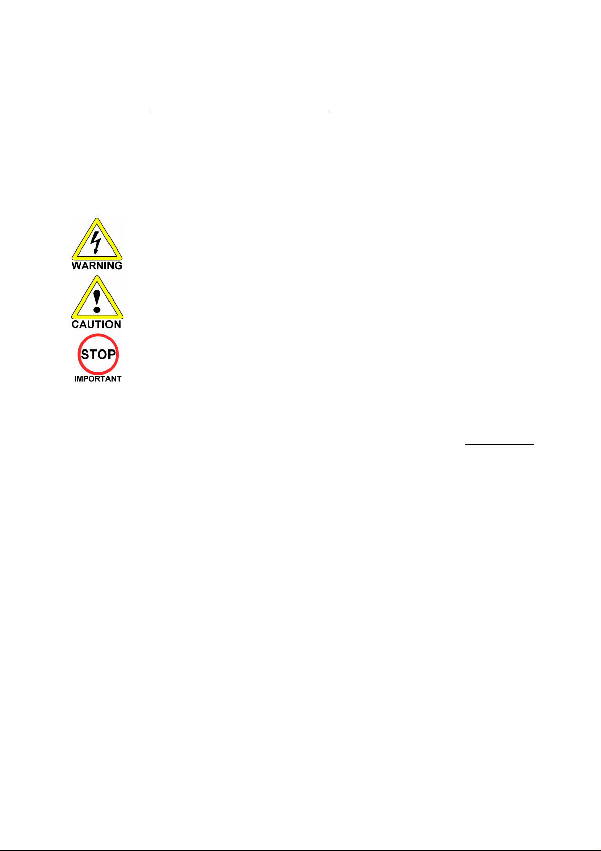
Depending on the potential risk, terms such as” WARNING!” “CAUTION” and “IMPORTANT!” are used where an
explanation is given that requires special attention. SEGA is not responsible for injury or damage caused by use in a
manner contrary to the instructions given in this document.
In order to prevent accidents warning stickers and printed instructions are applied in the places where a potentially
hazardous situation relating to the product could arise. Be sure to comply with these warnings.
Indicates that mishandling the product by disregarding this warning will cause a potentially
hazardous situation that can result in death or serious injury.
Indicates that mishandling the product by disregarding this caution will cause a potentially
hazardous situation that can result in personal injury and or material damage.
This is cautionary information that should be complied with when handling the product.
Indicates that mishandling the product by disregarding this will cause a potentially
hazardous situation that may not result in personal injury but could damage the product.
Be sure to turn off the power and disconnect from the mains supply before working on the machine.
Ensure that the correct fuses are fitted to the machine. Details of these are enclosed in the Service Manual.
Ensure that only qualified Service Engineers perform any maintenance work on the machine.
Specification changes, removal of equipment, conversion and/or additions not designated by SEGA are not permitted
and will invalidate this product’s CE conformity.
Warning labels or safety covers for personal protection etc, are component parts of the product. A potential hazard
will be created if the machine is operated while any parts have been removed. Do not operate the product if any
doors, lids or protective covers become damaged or lost. SEGA is not liable in any whatsoever for any injury and/or
damage caused by specification changes not designated by SEGA.
Before installing the product, check for the Electrical Specification Sticker, SEGA products have a sticker on which the
electrical specifications are detailed. Ensure that the product is compatible with the power supply voltage and
frequency requirements of the location in which the machine is to be installed.
Install and operate the machine only in places where appropriate lighting is available, allowing warning stickers to be
clearly read.
To ensure maximum safety for customers and operators, stickers and printed instructions describing potentially
hazardous situations are applied to potentially hazardous locations. Ensure that the product’s operating location has
sufficient lighting to allow any warnings to be read. If any sticker or printed warning is removed or defaced, do not
operate the machine until an identical item has replaced it.
Exercise great care when handling the monitor (applies only to product with monitor). Some of the monitor (TV) parts
are subject to high-tension voltage. Even after turning the power off some components are liable to high-tension
voltage. Only qualified service engineers should perform monitor repair and replacement.
In cases where commercially available monitors and printers are used, only the items relating to this product are
contained in this manual. Some commercially available equipment will have functions and reactions not referred to in
this manual. This manual should be read in conjunction with the specific manufacturer’s manual for such equipment.
Descriptions contained herein may be subject to change without prior notification.
The contents described herein are fully prepared with due care. However, should any question arise or errors be found
please contact SEGA AMUSEMENTS EUROPE LTD.
3
Page 5

1.1. INSPECTIONS IMMEDIATELY AFTER TRANSPORTING THE PRODUCT
TO THE LOCATION
• Only QUALIFIED SERVICE PERSONNEL should carry out inspection.
Normally, at the time of shipment, SEGA products are in a state to allowing usage immediately after
transporting to the location. Nevertheless, an irregular situation may arise during transportation preventing
this. Before turning on the power, check the following points to ensure that the product has been
transported safely.
• Are then any dented parts or defects (cuts, etc.) on the external surfaces of the product?
• Are castors and leg adjusters present and undamaged?
• Do the power supply voltage and frequency requirements meet with the local supply?
• Are all wiring connectors correctly and securely connected? Unless connected in the correct
direction, connector connections cannot be made successfully. Do not insert connectors forcibly.
• Are all IC’s of each IC BD firmly inserted?
• Does the power cord have any cuts or dents?
• Do fuses meet the specified rating?
• Are such units such as monitors, control equipment, IC BD, etc. firmly secured?
• Are all earth wires connected?
• Are all accessories available?
• Can all doors and lids be opened with the accessory keys and/or tools?
4
Page 6
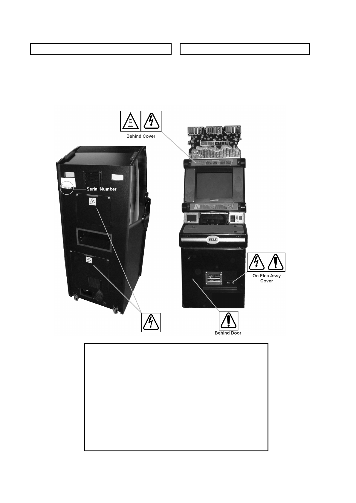
CONCERNING THE STICKER DISPLAY CONCERNING WARNING STICKERS
SEGA product has stickers describing the product
manufacture number (Serial Number) and
electrical specification. If you require service
assistance you will require the Serial Number.
Identical machines may have different parts fitted
internally. Only by quoting the Serial Number will
the correct parts be identified.
SEGA product has warning displays on
stickers, labels or printed instructions
adhered/attached to or incorporated in the
places where hazardous situations can arise.
The warning displays are intended for the
accident prevention of customers and service
personnel.
SPECIFICATIONS
Installation Space (mm): 650 (W) 940 (D)
Height (mm): 1576
Height with Pop Panel (mm): 1916
Weight (kg): 100 Kg (approx.)
Rated Voltage (VAC): 220 - 240
Rated Current (A): 1
Note: Descriptions in this manual are subject to change without prior notice.
5
Page 7

2. INTRODUCTION TO THIS SERVICE MANUAL
SEGA ENTERPRISES LTD., supported by its experience in electronic high technology of VLSI’s,
microprocessors etc. and with a wealth of experience, have for more than 30 years been supplying various
innovative and popular games to the world market. This Service Manual is intended to provide detailed
descriptions together with all the necessary information covering the general operation of electronic
assemblies, electro-mechanicals, servicing controls, spare parts, etc. as regards this new SEGA product.
This manual is intended for those who have knowledge of electricity and technical expertise especially in
IC’s, CRT’s, microprocessors etc. Carefully read this manual to acquire sufficient knowledge before
working on the machine. Should there be any malfunction, non-technical personnel should under no
circumstances touch the internal systems. Should such a situation arise contact the nearest branch listed
below, or our head office.
SEGA AMUSEMENTS EUROPE LTD./ SEGA SERVICE CENTRE
Suite 3a
Oaks House
12 - 22 West Street
Epsom
Surrey
United Kingdom
KT18 7RG
Telephone: +44 (0) 1372 731820
Fax: +44 (0) 1372 731849
6
Page 8
3. INSTALLATION AND MAINTENANCE INSTRUCTIONS
• Only QUALIFIED SERVICE PERSONNEL should carry out installation and
maintenance.
3.1. HANDLING AND INSTALLATION PRECAUTIONS
When installing or inspecting the machine, be very careful of the following points and pay attention to
ensure that the player can enjoy the game safely.
The game must NOT be installed under the following conditions:
• Outside, the game is designed for indoor use only.
• In areas directly exposed to sunlight, high humidity, dust, excessive heat or extreme cold.
• In locations that would present an obstacle in the case of an emergency i.e. near fire equipment or
emergency exits.
• On unstable surfaces or surfaces subject to vibration.
• Where liquids, other than routine cleaning, may come into contact with the game.
Important:
• Only Qualified Service Personnel should install this machine.
• Be sure to switch the supply power OFF and remove the mains supply plug from the machine
before any work is carried out on the machine.
• Do not attempt to repair the PCB’s (Printed Circuit Boards) yourself. This will void the warranty.
The PCB’s contain static sensitive devices that could be damaged.
• Always return a faulty part to your distributor with adequate packaging and protection.
• When removing the plug from the mains always grasp the plug not the cable.
• Do not use a fuse that does not meet the specified rating.
• Make sure all connections are secure before applying power.
• Ensure that the mains lead is not damaged. If the mains lead is damaged in any
way there could be a danger of electric shock or a fire hazard.
• Ensure that the power supply is fitted with circuit protection. Using the power
7
supply without circuit protection is a fire hazard.
Page 9
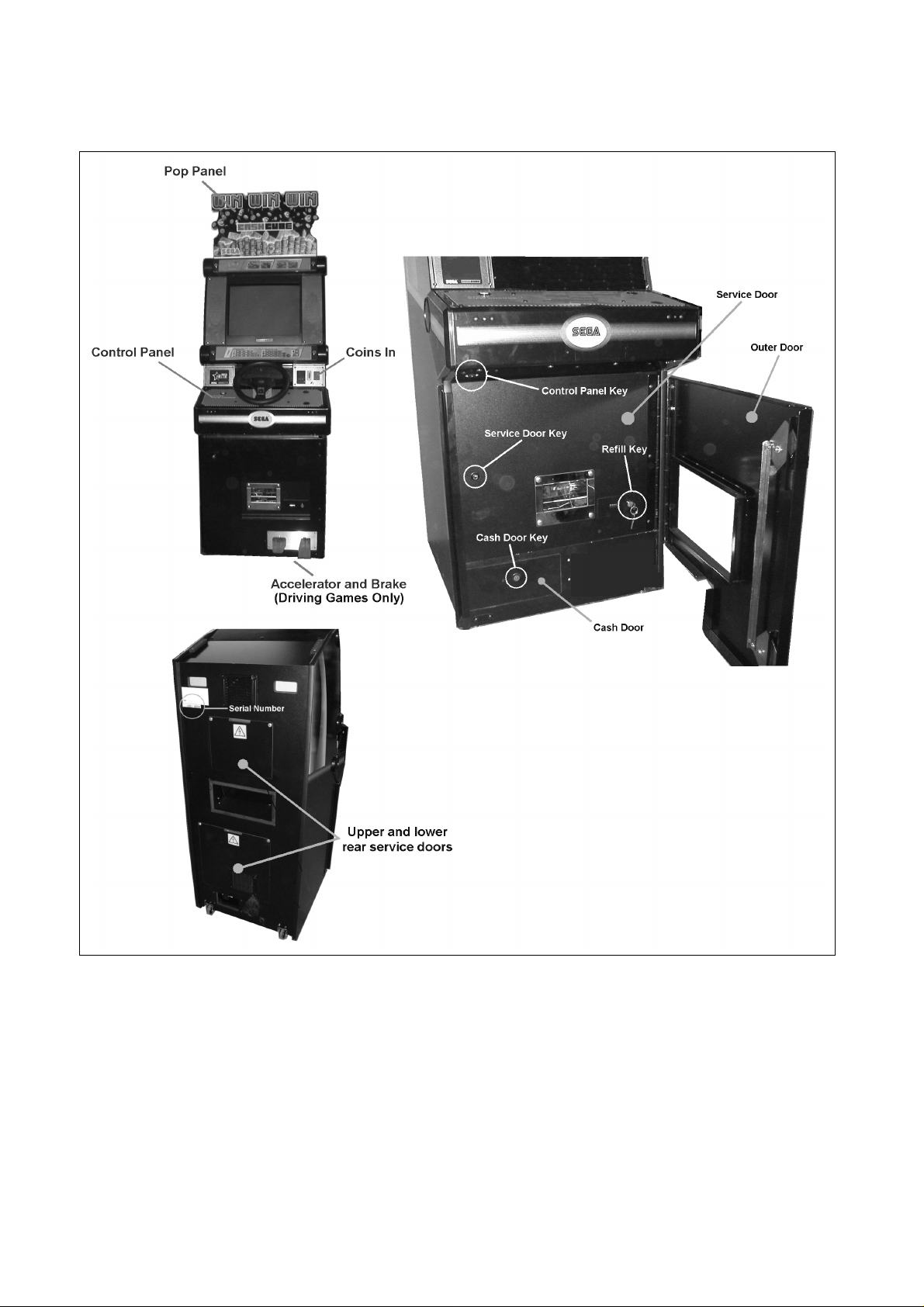
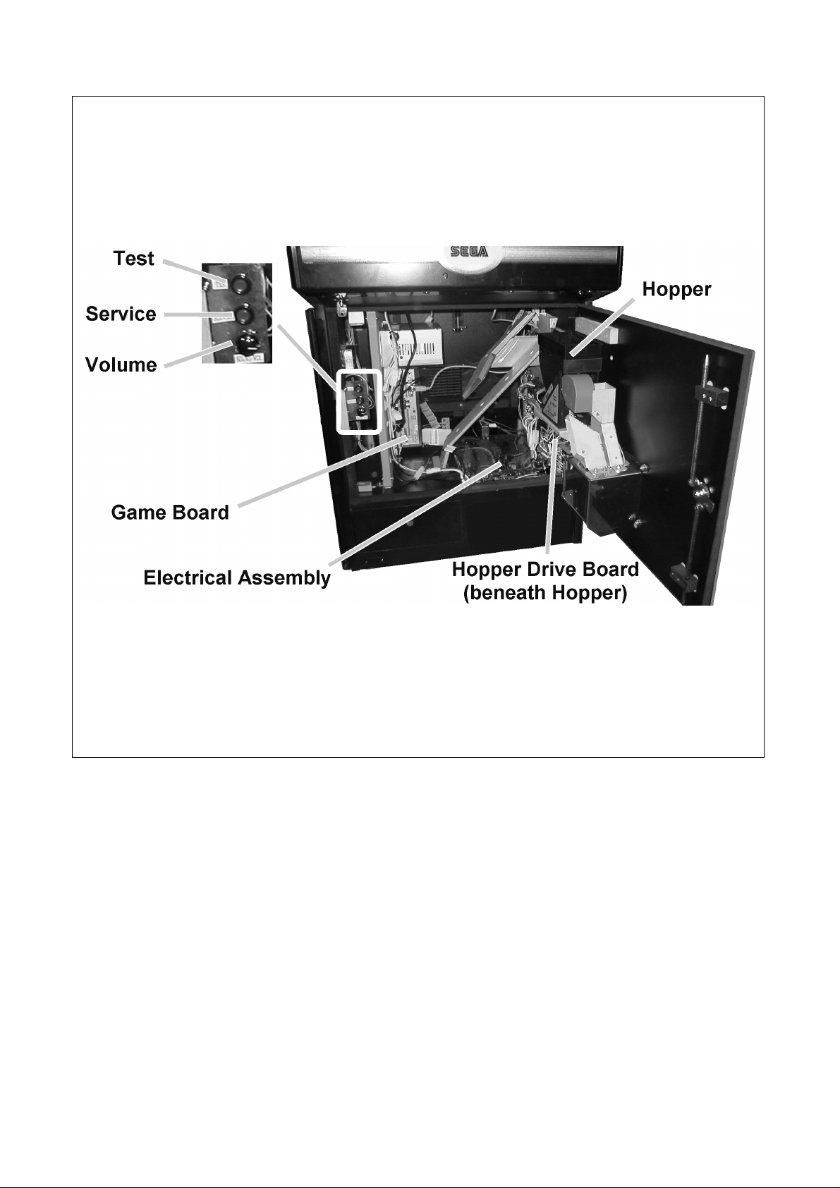
3.2. NAME OF PARTS
8
Page 10
9
Page 11
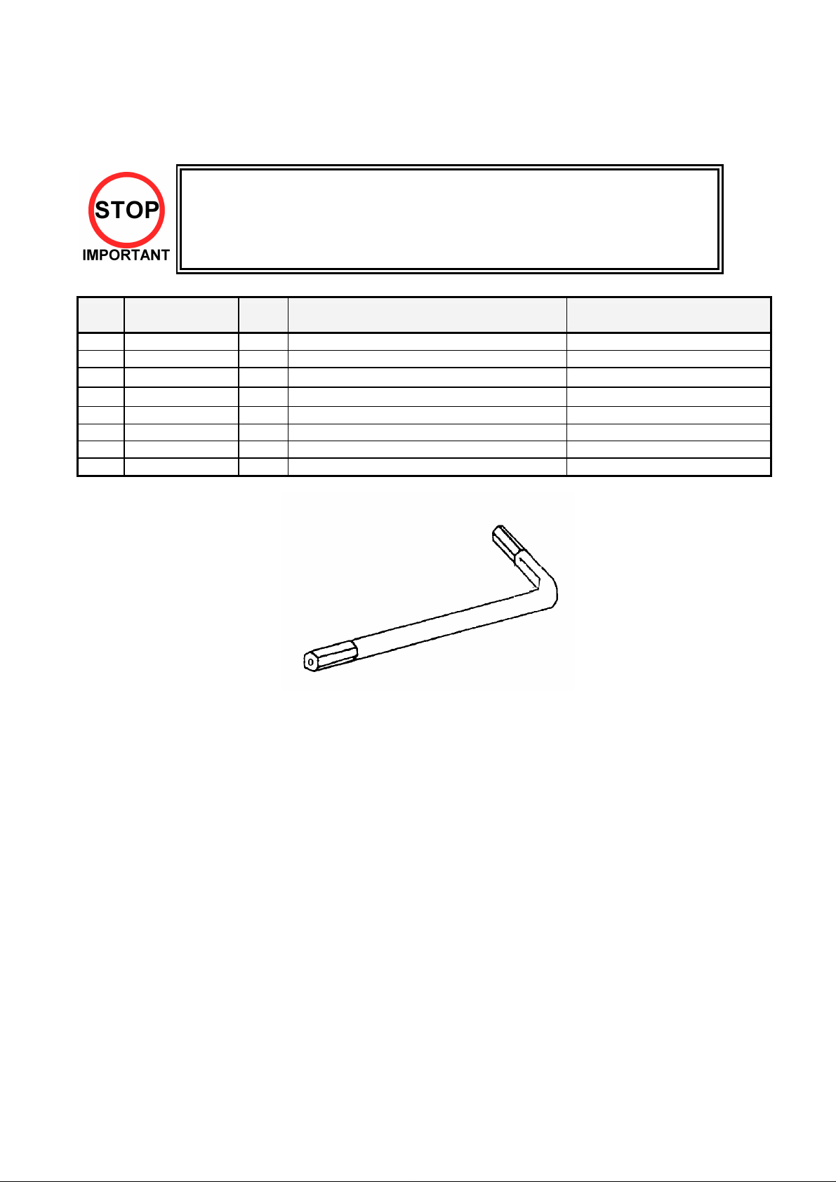
3.3. ACCESSORIES
The machine is supplied with an installation kit. Please ensure the following parts are supplied:
• The Installation Kit will be placed in the Cashbox. However larger items (e.g. the
Pop Panel) will be placed in the recess beneath the Test and Service buttons
inside the cabinet body.
• You must ensure that these items are removed before the machine is powered
up.
No. PART NUMBER QTY DESCRIPTION COMPONENT REFERENCE
1 PUB-5006 1 POP CASHCUBE
2 220-5753 1 VOL CONT B-5K OHM (TOCOS) spare
3 SAECE-122
401 RND-0050
402 OS1019 1 SELF SEAL BAG 9X12.3/4
404 PK0061 0.025 BUBBLE WRAP LARGE 1.5M X 45M
405 540-0006-01 1 WRENCH M4 TMP PRF
406 540-0015-01 1 WRENCH M6 TMP PRF
1
DECLARATION OF CONFORMITY CKP
1
SERVICE MANUAL CKP PUB SWP
Items 405 & 406 - Tamperproof TORX wrench.
10
Page 12
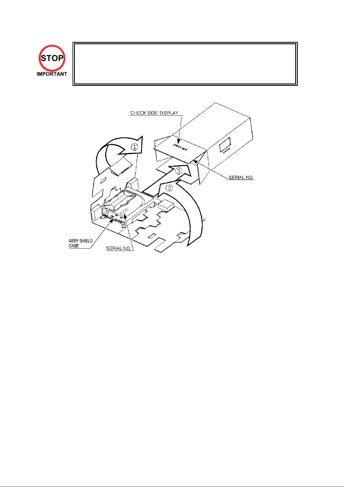
• When returning the GAME BOARD for repair or replacement, be sure to
package the entire ASSY SHIELD CASE in the original card transit box THERE ARE NO USER-SERVICEABLE PARTS INSIDE.
• Failure to return the GAME BOARD in this manner may invalidate the
warranty.
Wrap the ASSY SHIELD CASE with the packaging material and put it in the original transit box as shown.
Putting it upside down or packing other than as shown can damage the GAME BOARD and parts.
11
Page 13
3.4. ASSEMBLY INSTRUCTIONS
• Perform the assembly by following the procedure herein stated. Failure to
comply with the instructions, for example, inserting the plug into an outlet at
a stage not mentioned in this manual can cause an electric shock
• Assembling should be performed as per this manual. Since this is a
complex machine, erroneous assembling can cause damage to the
When carrying out the assembly work, follow the procedure in the following three item sequence:
machine, or malfunction to occur.
• Do not attempt to complete this work alone, a minimum of 2 people are
required.
• Only QUALIFIED SERVICE PERSONNEL should carry out assembly.
STEP 1
STEP 2
STEP 3
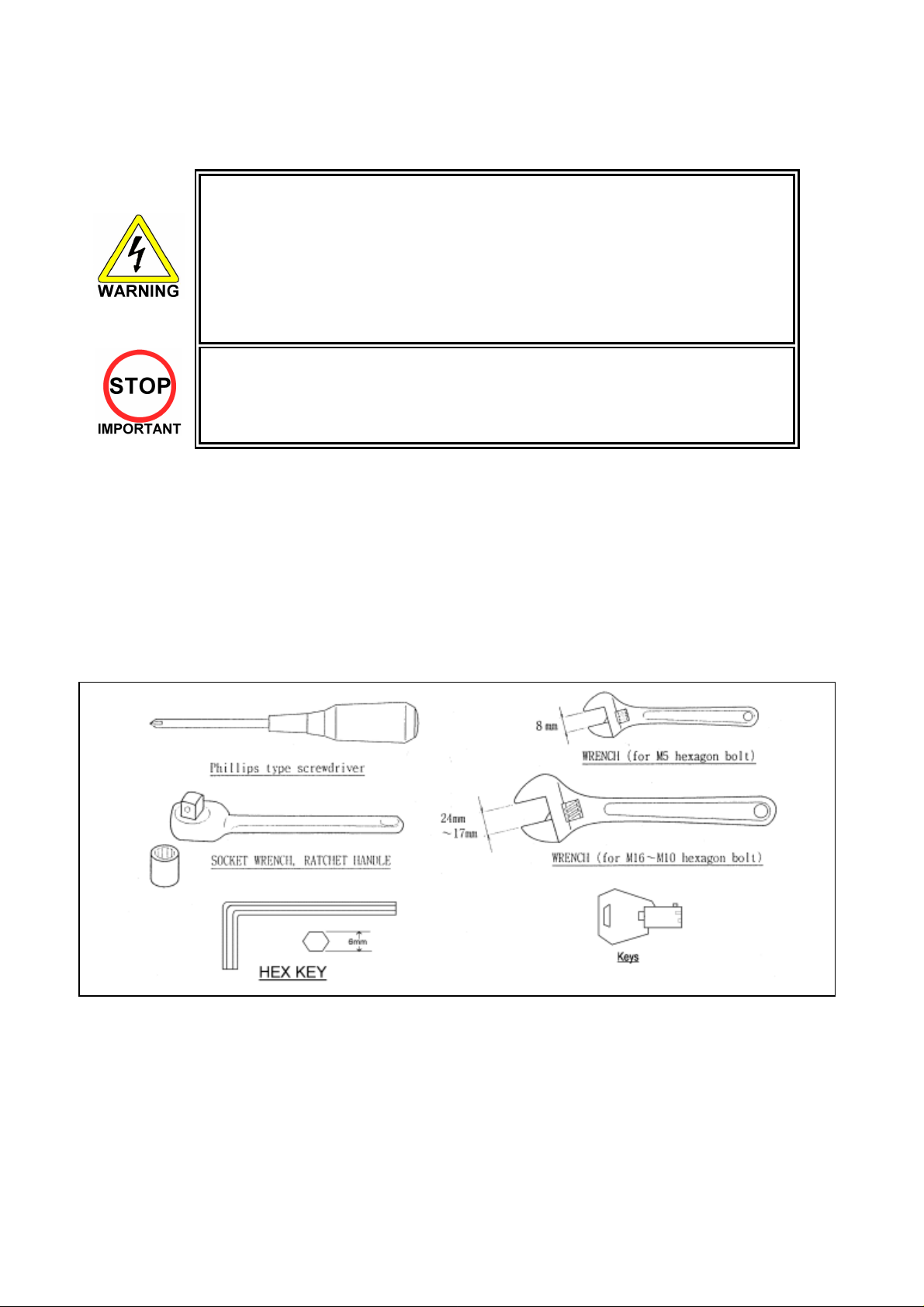
Note that the parts contained within the installation kit are required for the assembly work.
The following tools will be required when installing this machine:
INSTALLING THE POP PANEL
SECURING IN PLACE (LEG ADJUSTER ADJUSTMENT)
CONNECTION TO THE POWER SUPPLY
12
Page 14
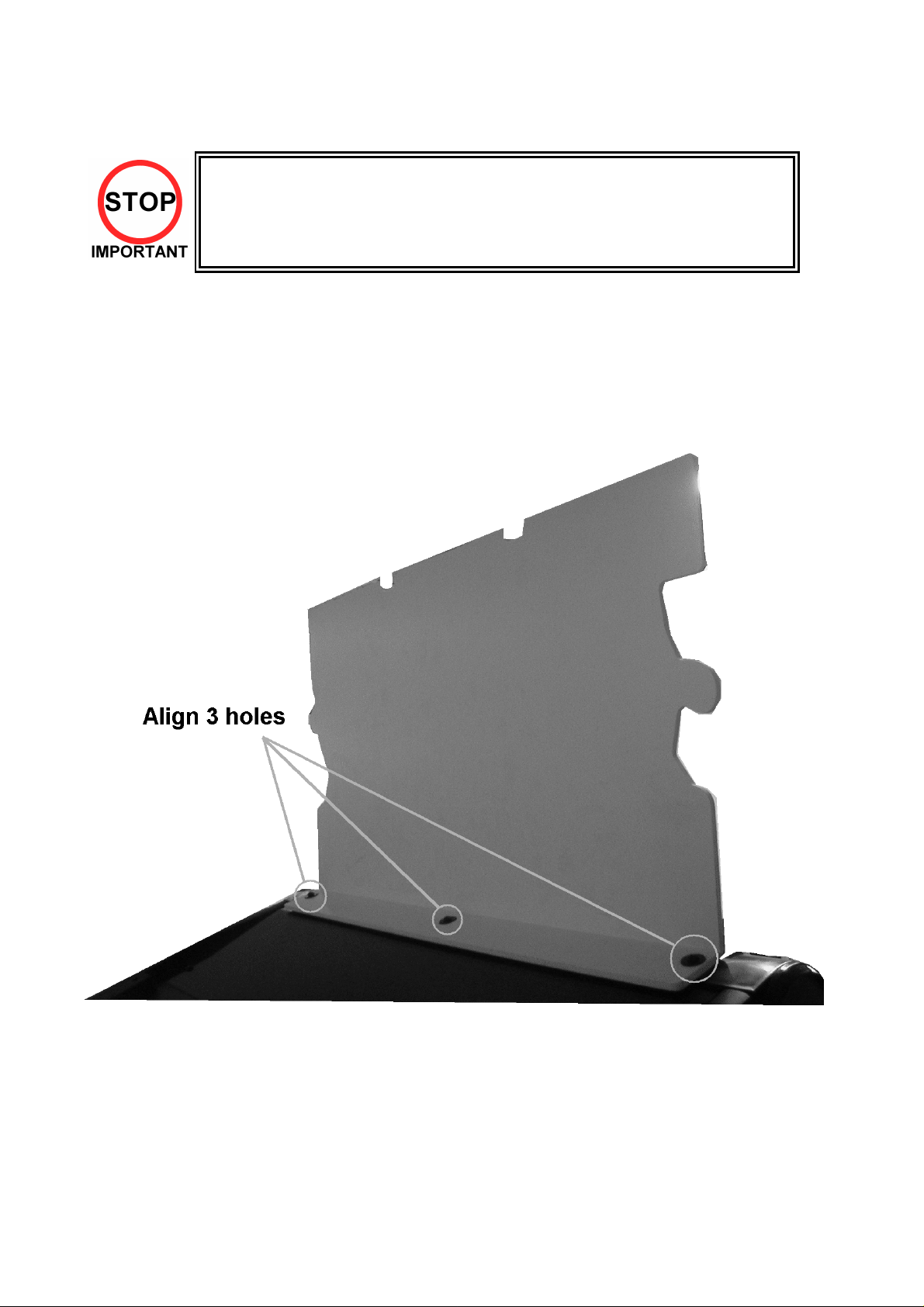
3.4.1. INSTALLING THE POP PANEL.(PUB-5006)
• QUALIFIED SERVICE PERSONNEL should only carry out this operation.
The Pop Panel picks up on the three top fixings of the Monitor Mask Moulding.
To fit:
1 Remove the three screws and washers on top of the Monitor Mask Moulding.
2 Offer up the Pop Panel and align over three fixing holes.
3 Re-fix the screws and washers.
4 Ensure the Monitor Mask Moulding is pushed back and seated properly to the cabinet.
13
Page 15
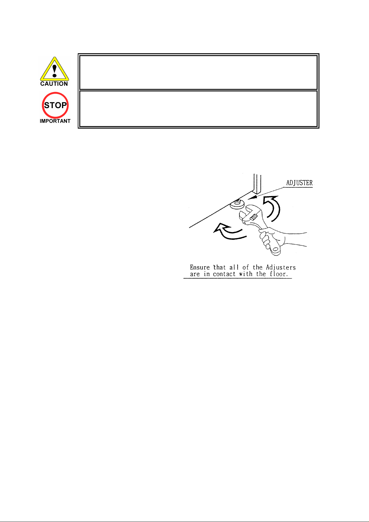
3.4.2. SECURING IN PLACE (LEG ADJUSTER ADJUSTMENT)
• The nominal position for the leg adjusters is fully retracted. Only
extend them if the machine is sited on an uneven surface.
• Only QUALIFIED SERVICE PERSONNEL should carry out this operation.
This machine has two castors (at rear) and two leg adjusters (at front). Where the installation is flat and
level, the adjuster should not need to be extended. Only extend the adjusters to prevent the machine from
rocking.
To extend the led adjusters:
1. Use a wrench to turn them until the machine is
stable and level.
Ensure adequate ventilation is maintained by ensuring there is at least a 150mm gap between the
back on the machine and any wall.
14
Page 16
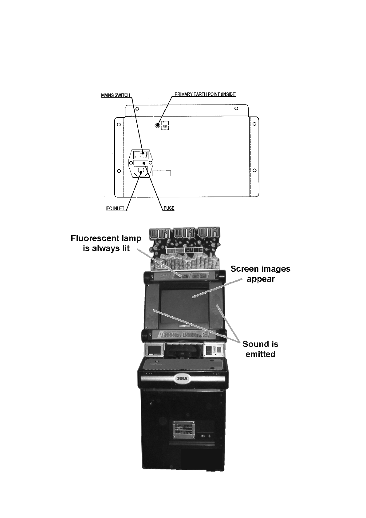
3.4.3. CONNECTION TO THE POWER SUPPLY
To connect the machine to the power supply:
1. With the Mains Switch in the ‘O’ position, insert the IEC mains lead plug into the IEC socket.
2. Turn the machine on by switching the Mains Switch to the ‘I’ position.
15
Page 17
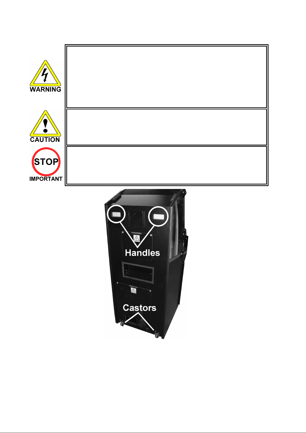
3.5. MOVING THE MACHINE
• When moving the machine, be sure to remove the plug from the power
supply. Moving the machine with the plug inserted can cause the power cord
to be damaged, resulting in a fire or electric shock.
• When moving the machine, retract the leg adjusters fully. During movement
pay careful attention so that the casters or leg adjusters do not damage any
other cabling laid on the floor. Such damage could result in a fire or electric
shock.
• Do not push the upper part of the cabinet. Failure to observe this can cause
the cabinet to fall forwards and result in accidents.
• When transporting the machine, be sure to hold the handles on the rear of
the cabinet. Inclining the machine by holding portions other than the handles
can damage the cabinet and/or the floor surface.
• Do not push the pop panel. Failure to observe this may damage the
installation portions and may cause unexpected accidents.
• The machine weighs approximately 100Kg and should only be moved by a
minimum of 2 people.
To move the machine:
1. Using the handles at the back of the cabinet, tilt the cabinet back until it is balanced safely on the
rear castors. EXTREME CARE SHOULD BE TAKEN DURING THIS OPERATION TO AVOID
INJURY OR DAMAGE TO THE MACHINE.
2. Carefully roll the machine to the desired position.
3. Tilt cabinet forward until front legs are in contact with the ground – CAUTION, THE MACHINE
MAY PULL FORWARDS.
4. Adjust the leg adjusters to ensure cabinet is square and steady if required.
16
Page 18
3.6. ELECTRICAL ASSEMBLY
• Before performing work, be sure to turn power off. Working with power on can
cause an electric shock or short circuit.
• Use care to ensure the wiring is not damaged. Damaged wiring can cause
electric shock or short circuit.
• Touching parts of the machine other than those specified here can cause electric
shock of short circuit.
• This procedure to be carried out only by QUALIFIED SERVICE PERSONNEL.
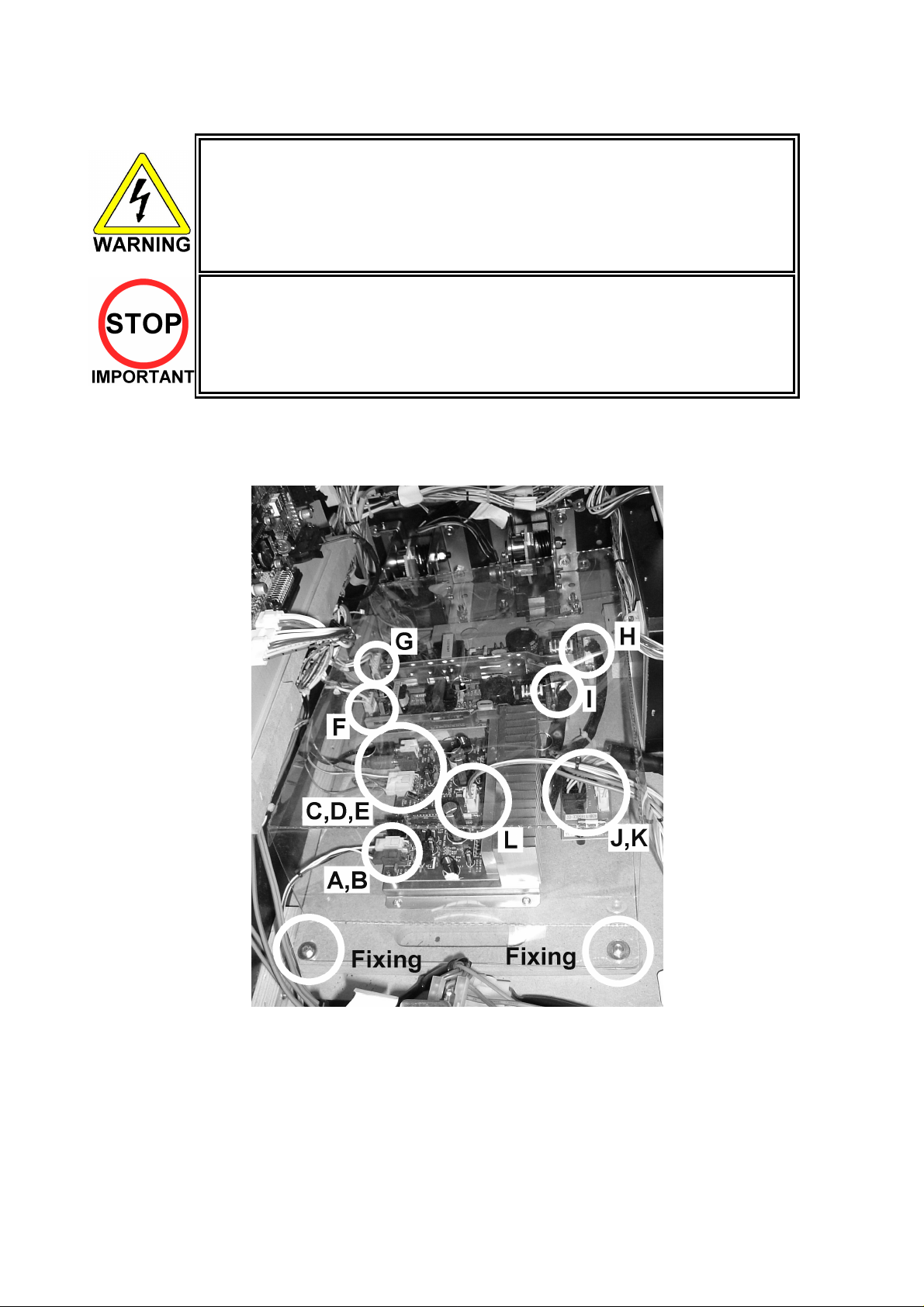
3.6.1. REMOVING THE ELECTRICAL ASSEMBLY
1. Remove the two fixings (bolt m4x30 and washer) securing the board.
2. Remove the plastic board cover.
3. Uncouple the loom connectors A to L.
4. Carefully slide the board out from the rear of the cabinet ensuring no damage takes place to the
board.
17
Page 19
3.7. CONTROL PANEL
• Before starting work, ensure that the cabinet is isolated from the mains by
switching off and removing the IEC mains lead from the wall outlet.
• Be careful not to damage wiring. Damaged wiring can cause electric shock
and short circuits.
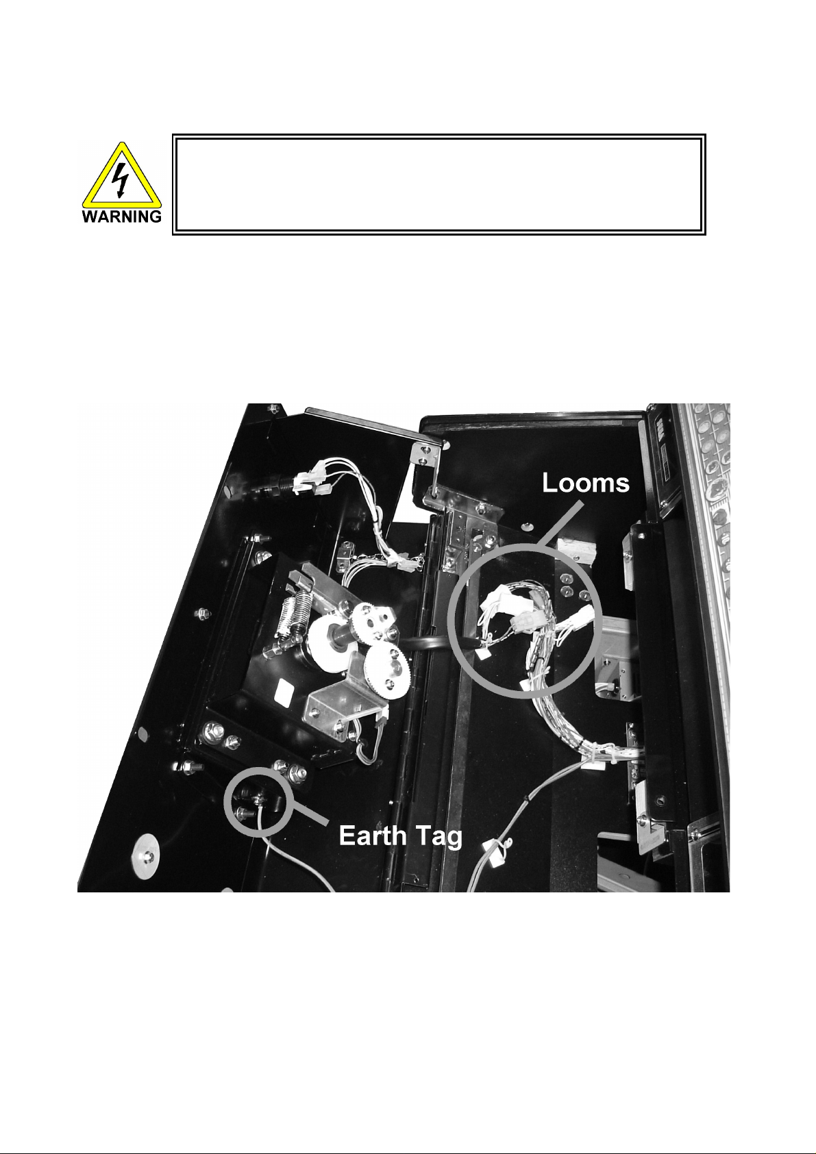
3.7.1. REPLACING THE CONTROL PANEL
1. Power OFF the machine and remove the IEC lead from the wall outlet.
2. Remove the 2 M6 security screws ion the top of the Panel.
3. Unlock the Control Panel using the Control Panel Key and open the Panel.
4. Disconnect the looms and the earth tag.
Note: This illustration may not reflect the actual control panel shipped.
18
Page 20
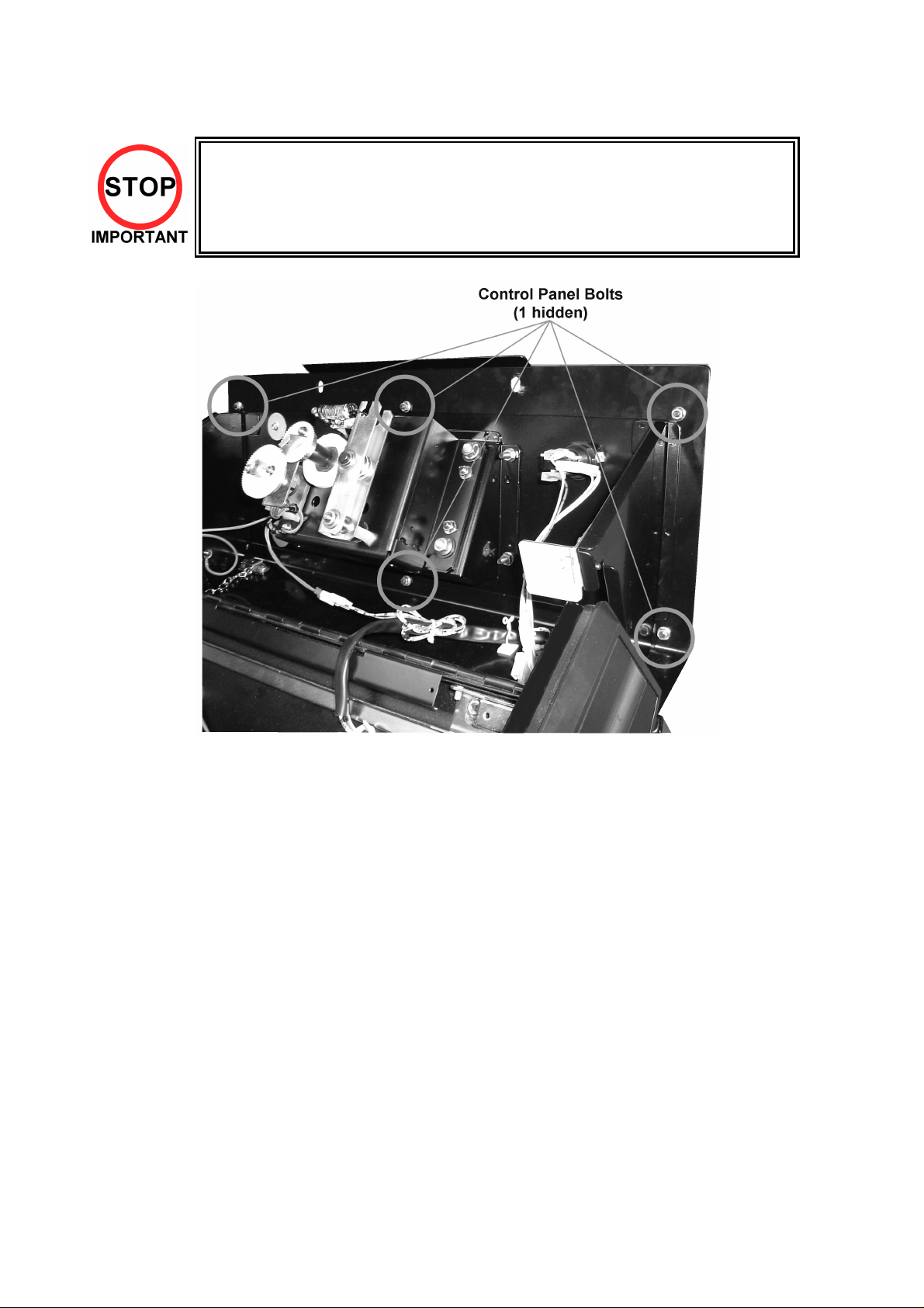
5. Remove the 6 bolts that secure the Control Panel in place.
Be sure to support the weight of the control panel when doing this!!
6. Remove the Control Panel
Note: This illustration may not reflect the actual control panel shipped.
19
Page 21
3.8. ACCELERATOR AND BRAKE
• Before performing work, be sure to turn power off. Working with power on can
cause an electric shock or short circuit.
• Use care to ensure the wiring is not damaged. Damaged wiring can cause
electric shock or short circuit.
• Touching parts of the machine other than those specified here can cause electric
shock of short circuit.
• Before starting this procedure, extend the leg adjusters far enough to enable
access to the bolts and bolt plates located beneath the cabinet. If the access gap
is not sufficient, the machine will have to be tilted or placed in its back
• Tilting or placing the machine on its back is a hazardous procedure and
should only be carried out by QUALIFIED SERVICE PERSONNEL.
• The Coin Hopper and Cash Box should be emptied before moving the machine
to prevent coins escaping into the cabinet body.
If the operation of the Accelerator and Brake pedals is unsatisfactory and not remedied by adjustment of
the VOLUME SETTING in the TEST MODE, the cause may be mesh failure of the Volume Gear or a
faulty Volume potentiometer. Follow the procedure below to adjust the Volume Gear mesh or replace the
Volume potentiometer.
When the pedals are depressed fully, if the Volume shaft is rotating within the movable range, the Volume
is not feared to be damaged. Use the procedure described herein to position the VR such that the correct
values are displayed at both extremes of pedal travel.
Note: It will be easier to remove the Pedals if the Electrical Assembly is removed
beforehand. See Section 3.6.1 for information on how to remove the assembly.
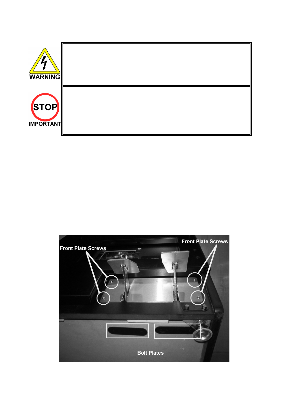
3.8.1. REMOVING THE PEDALS
Note: The pedals may differ slightly form those illustrated.
1. Turn the power switch OFF and remove the IEC cable.
2. Remove the four Front Plate screws then slide the Plate up and away from the pedals.
20
Page 22
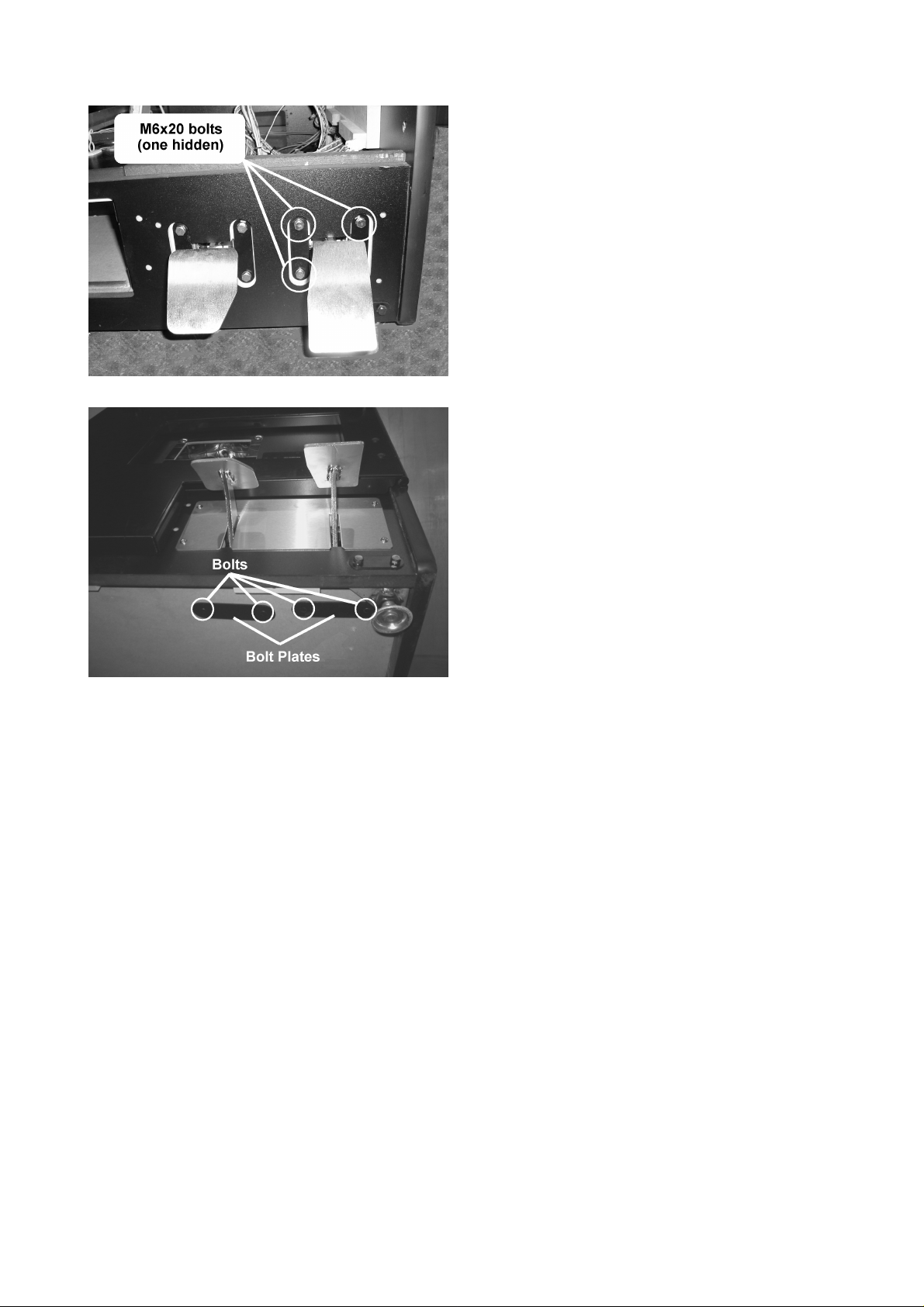
3. Remove the four pedal bolts (per pedal) securing
the pedal to the front of the cabinet.
4. Remove the bolts and bolt plate from beneath
the cabinet.
21
Page 23
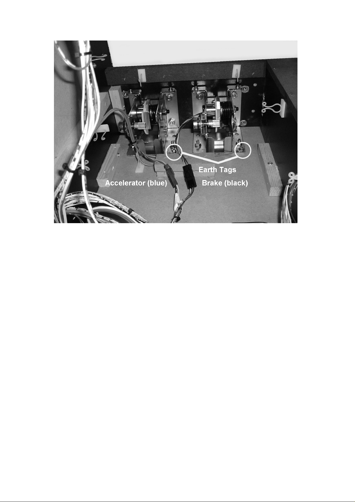
Note: In this illustration the Electrical Assembly is removed.
5. Disconnect the earth tag and connector block.
The connector block colours are as follows:
Blue = Accelerator, Black = Brake.
6. The Pedal can now be removed by sliding it into the cabi net.
22
Page 24
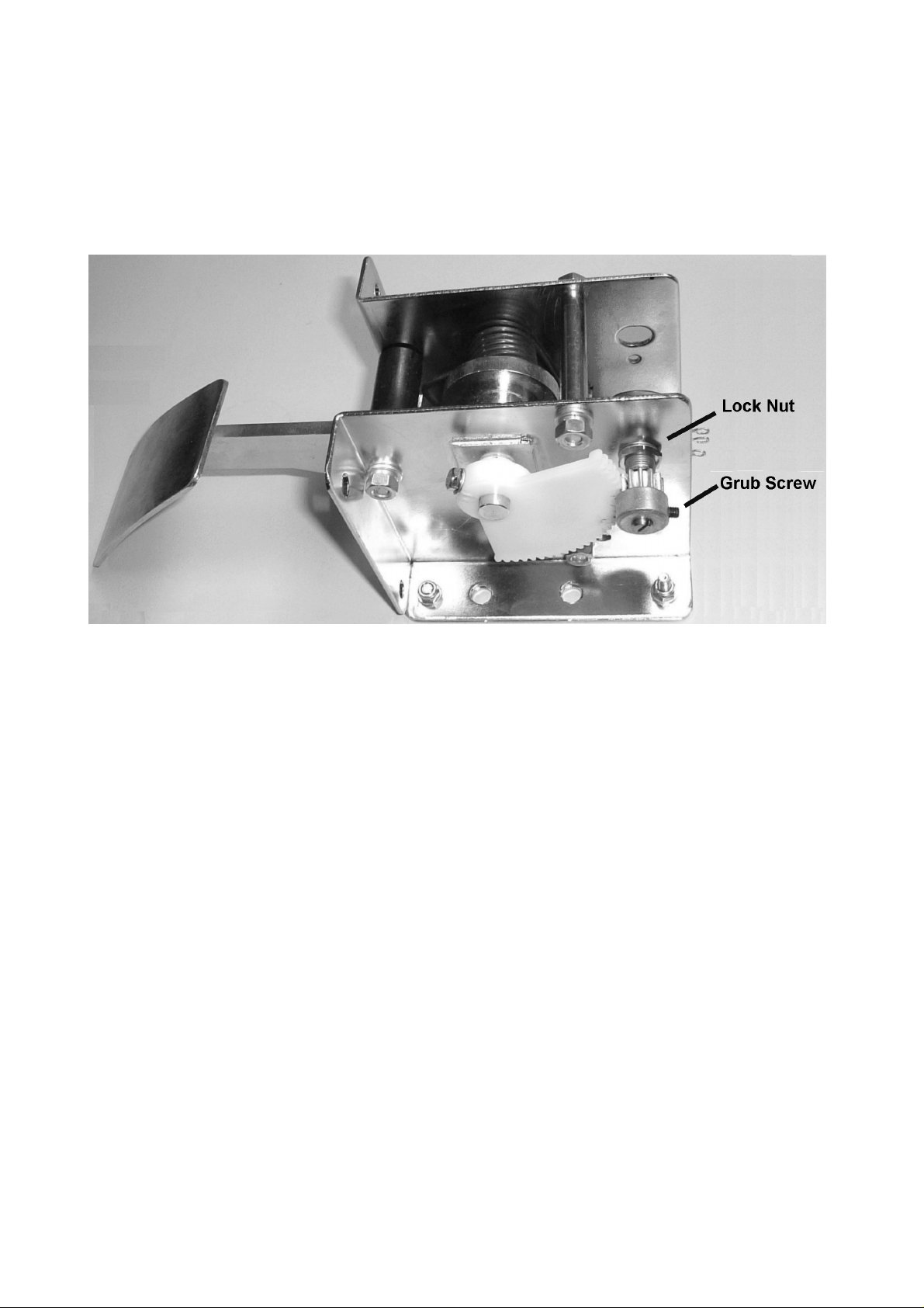
ADJUSTMENT:
1. Loosen the grub screw, and adjust the volume angle for optimum gear mesh.
2. Tighten the grub screw.
3. Check the volume setting in Section 8.2.6.
3.8.2. ADJUSTING OR REPLACING THE VOLUME
REPLACEMENT:
1. Loosen the grubscrew.
2. Slide off the gear cog.
3. Undo the lock nut.
4. Remove the volume.
5. Re-install in reverse order.
6. Check the volume setting in section 8.2.6
23
Page 25

3.8.3. GREASING
• When performing work, be sure to turn power off. Working with power on can
cause an electric shock or short circuit.
• Use only synthetic grease (grease or spray) as plastic parts are used. Do not
use mineral based greases.
• Applying grease to parts other than those specified can cause malfunctioning or
Apply grease to the gear mesh portions once every three months. Use a proprietary synthetic lubricant..
quality deterioration of parts.
24
Page 26
3.9. GAME BOARD
• When performing work, be sure to turn power off. Working with power on
can cause an electric shock or short circuit.
• Be careful not to damage wiring. Damaged wiring can cause an electric
shock or short circuit.
• The voltage/amperage ratings for the Game Board are 3.3V 12A, 5.0V 10A
and 12V 2A. To avoid risk of fire, never use any board with supply
requirements exceeding the above.
• When replacing the Game Board with one not of JAMMA standard, be sure
to use only the harness supplied by the manufacturer of the Game Board.
Using other harnesses constitutes a fire risk.
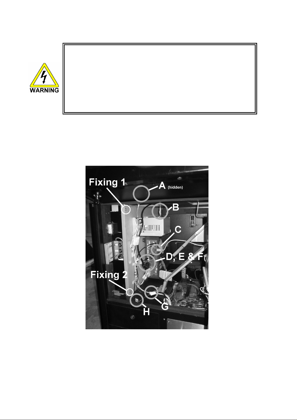
3.9.1. TAKING OUT THE GAME BOARD
To take out the game board, remove together with the wooden base on which the Game Board is mounted.
1. Turn power OFF by removing the IEC lead from the wall socket.
2. Disconnect all of the connectors A to H as shown below.
3. Remove fixings 1 and 2.
4. Slide the board assembly out from the cabinet being careful to avoid any damage during removal.
25
Page 27
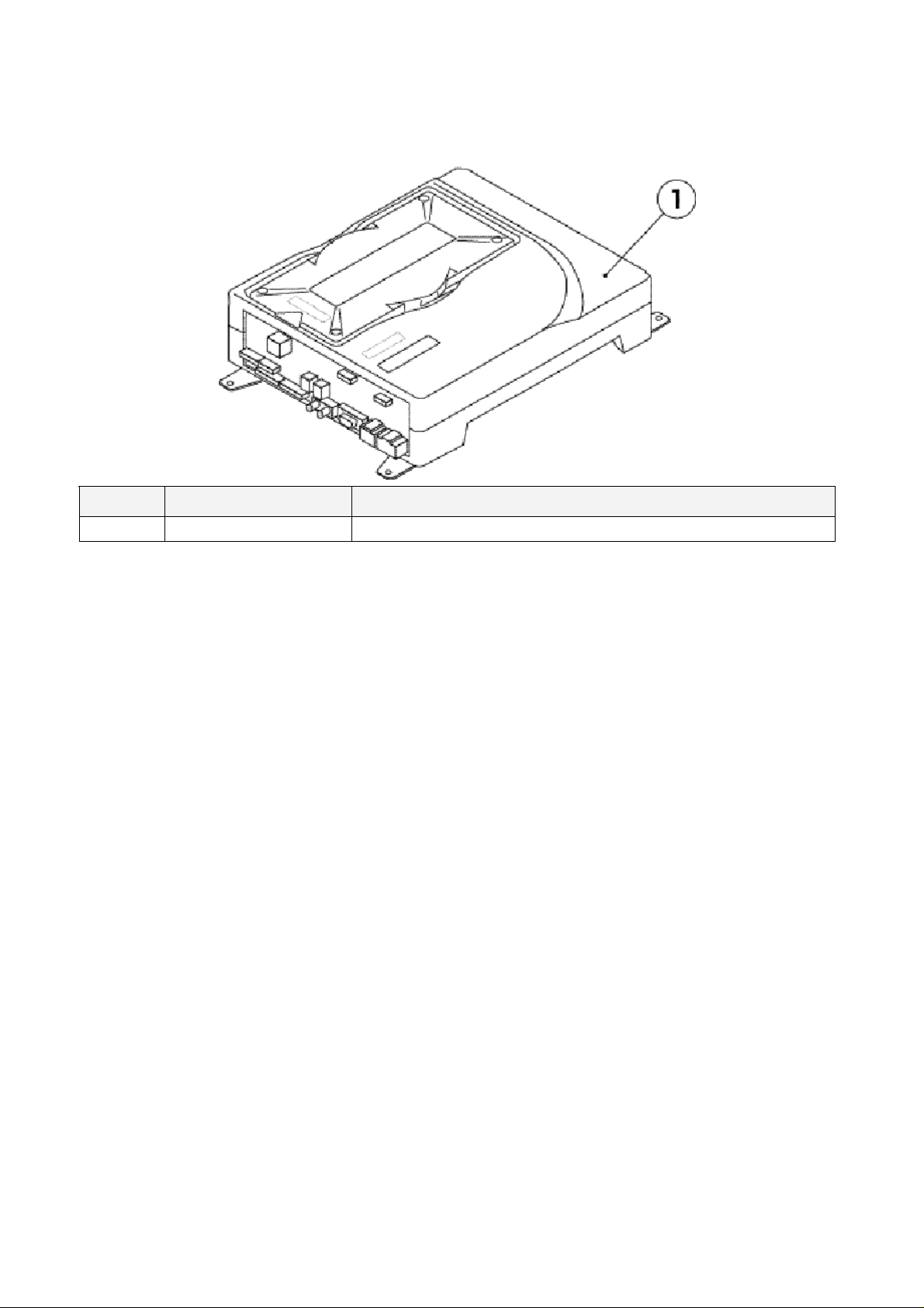
3.9.2. COMPOSITION OF GAME BOARD
PART NO. DESCRIPTION
1 840-0137D-02 ASSY CASE NAT CKT PUB EXP
26
Page 28

3.10. MONITOR ADJUSTMENT
The monitor adjustment pcb is located behind the logo plate on the opposite side to the coin entry bezel.
Rotate retaining
bracket to free
Logo Plate.
To gain access to the pcb:
1. Open the control panel after removing the two M6 security screws and using the Control Panel key
(see section 3.7.1).
2. Loosen the retaining bracket held on with 1 M4 screw to the lower right of the Logo Plate. This
allows the bracket to rotate enabling the Logo Plate to be removed.
3. The Monitor Adjustment pcb is located directly behind this plate.
27
Page 29

Note:
Problems with the monitor that cannot be corrected by simple adjustment using the pcb are beyond the
scope of this manual. Please refer to the monitor manufacturer for further information.
Pentranic Limited.
4 Michaelson Square
Kirkton Campus
Livingston
Scotland
UK
EH54 7DP
www.pentranic.com
28
Page 30

3.11. TROUBLESHOOTING
reinstate the circuit protection device to its original
Check all harness connections for loose wires and
• Only QUALIFIED SERVICE PERSONNEL should carry out these procedures.
If a problem occurs, first check the wiring connections.
PROBLEMS CAUSE COUNTERMEASURES
When the main switch is
turned ON, the machine is
not activated
Incorrect power source/voltage. Make sure that the power supply/voltage are
The colour image on
the screen is incorrect
The on-screen image of the
monitor sways and/or
shrinks
Sound is not emitted Sound volume adjustment is not
Malfunctioning BD and Amp.
The fluorescent lamp
does not light up
The connector is disconnected
No coin recognition.
Or
Poor coin acceptance rate
Machine not paying out.
The power is not ON. Firmly insert the plug into the outlet.
correct.
AC Unit CIRCUIT PROTECTION
DEVICE (i.e.; fuse) was activated due
to an instantaneous overcurrent.
Incorrect monitor adjustment. Make appropriate adjustments. Refer to section
The power source and voltage are not
correct.
correct.
Connector connection is incorrect Check connector connection from Base to
Fluorescent lamp needs replacement Replace the fluorescent lamp.
Coin mech dirty. Clean mech.
Coin mech faulty. Replace coin mech.
Bad loom connections.
Mech not programmed. Replace mech.
Payout Gameboard faulty. Replace Payout Gameboard.
No coins or coins jammed in Hopper. Add coins or clear jam.
Faulty Hopper or Hopper drive PCB Replace hopper or drive PCB
Faulty Hopper internal or external loom
to motherboard or drive PCB
First, remove the cause of overcurrent and
status.
Then identify the cause of the fault on the item
which caused the overcurrent & fix.
3.10.
Make sure that the power supply and voltage are
correct.
Adjust the volume setting located near the Test
and Service switches.
Perform Sound Test to check it.
Speaker
Check connector connections behind the monitor
mask.
fitments.
Check connectors.
24V DC fuse blown on hopper drive
board.
Payout Gameboard faulty. Replace Payout Gameboard.
29
Check fuse.
Page 31

3.12. HOPPER ASSEMBLY
b.
NB.
The machine uses a Coin Controls 24V DC hopper assembly.
3.12.1.HOPPER OPERATION
Each disc contains a number of holes in which coins are held in short stacks. The motor drives the disc via
a gear train. As the disc rotates, the coin at the bottom of one of the stacks will make contact with the
ejector fingers and start to push the fingers back. Further rotation of the disc will cause the coin to start to
move outwards into the exit slot. At this point the spring will be free to pull the ejector fingers forward and
push the coin through the exit slot.
A LED transmitter and opto-receiver form an optical detector. The infrared light beam is routed across the
exit slot via a light guide. When coin passes through the exit the light beam will be broken and coin output
signal will be generated.
The hopper will automatically brake when power is interrupted, or machine placed in the off state, thus
preventing overrun and excessive coin payout.
An over current detection circuit reverses the hopper momentarily in the event of a coin jam, and then
attempts to continue payout. This oscillation of the disc will continue until either the coins are freed, the
hopper is switched off, or the overload trip switches. Should the latter occur the hopper supply must be
disconnected, the fault condition must be corrected and the trip be allowed time to cool (Approx. 30
seconds) before the hopper will start.
3.12.2.HOPPER ASSEMBLY FAULT FINDING
Coins fail to unjam
1. Ensure coin exit clear.
2. Ensure no incorrect coins or foreign objects are in the hopper.
3. Ensure no badly bent coins in hopper.
Clearing a coin jam
1. Open the Outer and Service doors to gain access to the Hopper area..
2. Detach the metalwork surrounding the hopper by removing the 2 screws and 3 nuts that hold it in
place.
3. Remove all coins from bowl.
4. Remove motor assembly from base.
5. Clear the jammed coin by either:
a. Rotating the disc manually first anti-clockwise then clockwise to free the coin.
OR
6. Remove any debris from the disc bed assembly.
7. Clean the exit window opto with a clean dry cloth.
8. Reassemble as described earlier.
9. Refill and test the hopper.
Motor fails to run.
1. Check 24v 5A fuse on the Hopper Drive Board.
2. Hopper over-current protective device tripped (Wait 30 seconds while supply off).
Over payout of coins
Push the coin back in using the edge of similar coin.
Common cause is damaged or bent coins. Do not return damaged coins to bowl.
1. Check opto area/coin exit for dirt.
Under Payout of coins
1. Ensure hopper contains sufficient coins.
2. Poor connection (check common return wires) to hopper.
30
Page 32

Dismantling the Hopper
1. Gently pull outwards the securing clips on the back of the base.
2. Tilt the bowl forward until it is clear of the clips.
3. Slide the bowl forward until the locating lugs, at the front of the bowl, are clear of the slots in the
base.
4. Lift the motor assembly out of the base.
5. Disconnect the cable from the motor assembly.
Hopper Assembly
1. Connect the cable to the motor assembly, ensuring that the 4-pin connector is the correct way
round.
2. Lower the motor assembly into the base, ensuring that the coin exit is in the rear exit position.
(Towards Coin exit position).
3. Locate the lugs, on the front of the bowl, into the slots at the front of the base.
4. Gently press down until the securing clips, on the base, click into the slots in the bowl.
Routine cleaning:
All accessible parts of the coin route should be cleaned periodically using a mild detergent on a damp
cloth. No spray solvents should be used. Particular attention should be paid to the opto sensor at the coin
exit to remove any build up of dirt.
31
Page 33

3.13. COIN MECHANISMS
The machine uses a Coin Controls SR5 Coin Mechanism.
3.13.1.COIN MECHANISM OPERATION (FOR UK MACHINES).
COINS ACCEPTED: 5P, 10P, 20P, 50P, £1, £2
COIN ROUTING
The coin mech automatically routes all coins
other than £1 coins to the cash box (exit C). £1
coins are routed to the hopper (exit A) until the
float is achieved, afterwards they are diverted to
the cash box (exit B). The float is maintained by
software counting the number of £1 coins
entered.
The coin mech exits are as follows:
A Hopper
B Cash Box
C Cas h Box
D Not Used.
SR5 – COIN CONTROL
ROUTING PLUG: 18 WAY
Pt No PUB-64101UK
5-7,8-15,1à13, 10à13, 12à13, 16à13, 17à13,
18à13
The diode direction is shown as ‘à’.
Note: Cash Payout - £1 Hopper only fitted.
3.13.2.COIN MECHANISM FAULT FINDING
There is a green diagnostic LED used to provide a visual indication of the mechanisms current operation
and error condition.
1. LED ON = Power ON
2. LED OFF = Power OFF
3. LED will flash OFF once when Coins or Tokens are accepted or if reject Lever is pressed.
4. LED will flash OFF twice if Coin or Token is unrecognised.
5. LED will flash OFF three times if validator or machine has inhibited Coin or Token.
6. LED will flash continuously when in Token Teaching Mode.
For further information on the operation of the coin mechanism, please refer to the Money Controls
website:
www.moneycontrols.com/support/
32
Page 34

3.14. FUSES
• Never touch places other than those specified. Touching places other than
those specified can cause electric shock and short circuit. Disconnect the
machine from the supply before attempting the replacement of any fuse.
• Only QUALIFIED SERVICE PERSONNEL should replace FUSES.
• Only replace fuses with ones of the same value and type.
There are a number of fuses used on this machine to protect the user and the machine from damage. Only
replace the fuse once you have removed the cause of its failure. Detailed below is a list of the fuses used,
their location and if relevant PCB reference:
PART NUMBER LOCATION TYPE & DETAILS QTY
514-5078-3150 STEREO AMP REF. F1, F2 5x20mm CERAMIC SB 3.15A 2
514-5078-4000 SWITCH REG REF. F1 5x20mm CERAMIC SB 4A 1
514-5078-5000 IEC INLET REF. F1 5x20mm CERAMIC SB 5A 1
514-5078-6300 CONN. BD. REF. F1 5x20mm CERAMIC SB 6.3A 1
There are also fuses located on the Monitor PCB. Refer to the monitor manufacturer for further
information.
33
Page 35

4. REFILL MODE
4.1. WHAT IS REFILL MODE?
The REFILL MODE is used to refill the Hopper with coins or to pay out coins from the Hopper. To enter
REFILL MODE, hold the Key Switch in the "ON" position for around one second. Setting the Key Switch
back to "OFF" will then exit REFILL MODE. Except during game play or in Test Mode, REFILL MODE can
be accessed at any time. However, it is possible to enter REFILL MODE during game play if a "HOPPER
EMPTY" error occurs.
There are two different submodes used in REFILL MODE, depending on the status of the machine doors.
When the doors are closed, "LANDLORD REFILL" is used, and when the front door or cash door are open,
"COLLECTOR REFILL" is used.
4.2. LANDLORD REFILL
During LANDLORD REFILL, a screen like the one below will be displayed.
LANDLORD REFILL Screen
Display Meaning
LAST WIN The number of wins in the last game.
FLOAT
During LANDLORD REFILL, the Hopper coin stock can be replenished by inserting coins into the coin slot.
It is possible to fill the Hopper up to the FLOAT maximum value setting (shown as 70 in the above table).
LAST WIN and FLOAT values will not be displayed under the default settings. To display these values,
change the display option in the MEMORY SETTING section of the HOPPER BOARD TEST Menu.
The number of coins in the Hopper. (current number / maximum number) Any coins
inserted beyond the maximum number will be diverted to the Cash Box.
34
Page 36

4.3. COLLECTOR REFILL
During COLLECTOR REFILL, a Screen like the one below will be displayed.
COLLECTOR REFILL Screen
Display Meaning
IN Total number of coins inserted.
OUT Total number of coins paid out.
REFILL Total number of coins refilled.
LAST WIN Same as LAST WIN in LANDLORD.
FLOAT Same as FLOAT in LANDLORD.
DUMP Number of coins paid out with Dump Switch.
In COLLECTOR REFILL mode, the Hopper coin stock can be replenished just like in LANDLORD, only in
COLLECTOR REFILL mode, coins can be added directly into the Hopper.
After refilling coins directly into the Hopper, be sure to press the Top Up Switch and set the FLOAT current
coin number to the maximum coin number. Neglecting to set the current coin number could result in a coin
overflow.
Also note that pressing the Dump Switch will release the entire Hopper coin stock.
35
Page 37

4.4. DEALING WITH A HOPPER EMPTY ERROR
Following is the procedure for dealing with a HOPPER EMPTY/JAM error:
1. Get a WIN in the game.
2. Payout will commence.
3. The error occurs (as shown in the figure below).
4. Set the Key Switch to ON and enter REFILL MODE.
5. Refill the coin stock.
6. Setting the Key Switch to OFF will exit REFILL MODE and return to payout.
7. End the game.
HOPPER EMPTY / JAM Error Occurrence 1
HOPPER EMPTY / JAM Error Occurrence 2
36
Page 38

4.5. METERS
The machine is fitted with three mechanical meters that record the following information:
• Total Coin In
Total of all the coins fed in through the coin mechanism.
• Total Coin Out
Total of all the coins paid out from the hopper.
• Total Coin Refill
Total of all the coins refilled through the coin mechanism
Note: These meters cannot be reset and therefore record the totals since the machine was delivered.
37
Page 39

5. DATAPORT
5.1. WHAT IS THE DATAPORT?
The DATAPORT is a data organization device used to aid U.K. AWP/SWP income collection. The
DATAPORT, when connected to the game unit, can exchange information with the HOPPER BOARD
machine regarding settings and states, coin IN/OUT quantities, etc. via serial data transfer.
The DATAPORT and HOPPER BOARD share information, and typically when there is no response from
the DATAPORT an error will occur, but settings can be changed to prevent this from happening.
This change is made in the DATAPORT SETTING of the HOPPER BOARD TEST Menu (see section
8.2.4.6). The Menu item, however, is not normally displayed among the other setting selection items.
Displaying the Menu item requires a special dongle, explained in the next section (SETTING
PROCEDURE).
DATAPORT SETTING Menu.
5.2. SETTING PROCEDURE
The following procedure explains how to use a dongle to access the DATAPORT SETTING Menu and
change the aforementioned error display setting:
1. Make sure power is off and connect dongle.
2. Turn on power.
3. Enter HOPPER BOARD TEST Menu.
4. Change setting in DATAPORT SETTING.
5. Turn off power.
6. Disconnect dongle.
7. Turn on power.
38
Page 40

5.3. DATAPORT SETTING
In the DATAPORT SETTING Menu, two setting values can be changed.
The OPTION setting determines whether or not the HOPPER BOARD watches over communications from
the DATAPORT, and the CONDITION setting controls whether the OPTION setting is active perpetually or
temporarily.
Menu Item Content Setting Type
OPTION PROTOCOL setting PROTOCOL (watches over DATAPORT) / NON-PROT (does
not watch over DATAPORT)
CONDITION OPTION setting type FOREVER (perpetual) / TEMP (temporary)
Setting the CONDITION to TEMP will not eliminate the DATAPORT SETTING Menu item, however setting
CONDITION to FOREVER will render it hidden. The Menu item will remain hidden until connecting the
dongle as mentioned above.
DATAPORT SETTING Menu
Setting CONDITION to TEMP will result in the following screen (blue window) coming up whenever
restarting an application. Turning the Key Switch ON and OFF again will allow the application to startup.
Startup Screen with TEMP Setting
39
Page 41

5.4. ERROR
With CONDITION set to PROTOCOL, an error (#202) will result when there is no response from the
DATAPORT. This error will be cancelled when there is a normal response from the DATAPORT.
Error #202 Screen
40
Page 42

6. PERIODIC CHECK AND INSPECTION
The items listed below require periodic check and maintenance to retain the performance of the machine
and ensure safe operation:
• Be sure to check annually to see if the power cords are damaged, the plug
is securely inserted and that there is no dust in the interior of the machine or
between the socket and the power cord. Using the product in an unclean
condition may cause a fire or electric shock.
DESCRIPTION WHAT TO CHECK INTERVAL
CABINET Check Adjusters’ contact with surface Daily
MONITOR Cleaning CRT face
Check settings
GAME BD Setting check Monthly
CONTROL PANEL Input test Monthly
Speaker, sound Sound test, check volume adjustment Monthly
COIN SELECTOR Coin insertion test
Cleaning
POWER SUPPLY CORD Check condition Annually
INTERIOR
CABINET SURFACE
Clean (Do Not use water jet)
Clean (Do Not use water jet)
Weekly
Monthly
Monthly
Tri-Monthly
Annually
As required
6.1. CLEANING THE CABINET SURFACES
When the cabinet surfaces are badly soiled, remove stains with a soft cloth dipped in water or chemical
detergent (diluted with water) and squeezed dry. To avoid damaging surface finish, do not use such
solvents as thinner, benzene, etc. (other than ethyl alcohol), abrasives or bleaching agents. DO NOT USE
A WATER JET.
41
Page 43

7. CONTENTS OF GAME
7.1. HOW TO PLAY: POUND SETTING
1. Insert Coin
2. Press START BUTTON
3. Select the difficulty level between; novice, intermediate, difficult by using the steering, and then
confirm by pressing ACCELERATOR UNIT or START BUTTON.
4. DOSH DASH RACE
If you fail to reach goal within the time restriction it will be GAME OVER.
There are many items within the circuit. Aim for
star mark, avoid for skull mark, and then attempt
to reach the goal within the time restriction.
Time bonus will be added when reaching goal, try
for further bonus time by reaching goal in certain
time period.
42
Page 44

5. ALL OR NOTHING STAGE
Please press BRAKE UNIT in proper time,
taking wind gauge in account, to stop KART
within STOP AREA.
The ACCELERATOR UNIT will NOT be used.
If you succeed, you can win the prize achieved
in “4.DOSH DASH RACE”.
If you fail, it will be GAME OVER.
6. Continue
If you fail in 5. ALL OR NOTHING STAGE, you can retry ONCE.
If you wish to continue, please insert coin within time restriction.
43
Page 45

7. DOUBLE UP CHALLENGE
• For UK operation, this stage should not be enabled (see section 8.2.3). This
stage will be factory defaulted to OFF .
If you succeeded in both above 5 & 6, you
have a chance of doubling up the prize.
Look carefully for WIN and LOSE door, and
aim for WIN gate.
This “7. DOUBLE UP CHALLENGE” feature can be either set ON or OFF.
If you WIN prize doubles, but if you LOSE it
will be GAME OVER and no prize paid out.
44
Page 46

8. EXPLANATION OF TEST AND DATA DISPLAY
Use the switches on the VTS to enter the TEST MODE. This will allow you to carry out post installation and
periodic checks and adjustments. The following section details the function of each of the tests:
ITEM DESCRIPTION INTERVAL
INSTALLATION OF
THE MACHINE
MEMORY
PERIODIC CHECKS Periodically perform the following
CONTROL SYSTEM
MONITOR
IC BOARD MEMORY TEST
DATA CHECK
EXTERIOR
MAINTENANCE
COIN MECHANISM
When the machine is installed perform the following
checks:
• Check to see that each setting is as per the
standard settings input at the time of shipment.
• In the INPUT TEST mode, check each switch and
V.R.
• In the OUTPUT TEST mode, check each of the
lamps.
• In the MEMORY TEST mode check all of the IC’s
on the IC BD.
• On the TEST MENU screen choosing the MEMORY
TEST allows self-test to be performed. In this test
RAM & ROM are tested.
• MEMORY TEST.
• Ascertain each setting.
• In the INPUT TEST mode, test the control devices.
• In the OUTPUT TEST mode, check each of the
lamps.
• In the INPUT TEST mode, check each switch and
V.R.
• Adjust or replace each switch and V.R.
• In the C.R.T. TEST mode, check to ensure the
monitor is adjusted correctly
• Clean screen (switch off machine and remove the
plug)
• In the SOUND TEST mode, check the sound
related ROMs
• Check such data as held in the bookkeeping
screens, relating to number and length of plays
• Clean surfaces
• Lubricate seat sliders
• Check switch operation (if fitted)
Monthly
Monthly
Monthly
Monthly
Monthly
Weekly
Monthly
Monthly
Monthly
Monthly
45
Page 47

8.1. SYSTEM TEST MODE
• Setting changes made in SYSTEM ASSIGNMENTS, COIN ASSIGNMENTS and
GAME TEST MODE are stored only when the TEST mode is exited properly. If
the power is turned off before exiting, and changes made will be ineffectual.
• Do not activate any system test mode while the system is reading the GD-ROM
(if fitted), otherwise error messages may appear.
• Only QUALIFIED SERVICE PERSONNEL should carry out these procedures.
The SYSTEM TEST MODE allows the IC Board to be checked for correct operation, monitor colour to be
adjusted, and COIN and GAME ASSIGNMENTS to be adjusted.
The Test and Service button are located on the left-hand side of the cabinet behind the service door.
46
Page 48

To enter the Test mode:
1. After turning power ON, press the TEST Button to display the following menu:
2. Press the SERVICE Button to move the arrow to the desired item, and press TEST to select.
3. Select GAME TEST MODE to display the test menu for that specific game. For further information
about GAME TEST MODE, refer to the service manual for the game.
4. Upon finishing the test, select EXIT to return to the game.
8.1.1. RAM TEST
This screen carries out a test on the RAM on the NAOMI Main Board. The test begins immediately that the
screen appears.
TESTING NOW is displayed while the system is testing.
GOOD should appear next to each IC number if the RAM is satisfactory. BAD will appear next to
abnormal IC’s. The test takes about two and a half minutes to complete testing on all IC’s.
After testing, press TEST to return to the system menu screen.
47
Page 49

48
Page 50

8.1.2. JVS TEST
Use this test to check specifications of the I/O Board connected to the NAOMI Main Board, while INPUT
TEST can be performed on the input switches. First, I/O Board specifications are displayed.
Select from the following:
INPUT TEST: Proceed to the INPUT TEST of the I/O BOARD displayed.
NEXT NODE: In the case of more than two I/O Boards being connected, this proceeds to the
next I/O Board.
EXIT: Returns to the Menu Mode.
49
Page 51

8.1.3. INPUT TEST SCREEN
8.1.4. SOUND TEST
Select the sound test to check the status of the amplifiers, sound boards and speakers.
Press the SERVICE button or view change button to move the arrow to the desired test item.
Press TEST button to output the sound.
• Select the sound source with SERVICE.
• On pressing TEST, the test sound is
emitted from the selected source.
Front speakers are located on the Control Panel.
Rear speakers are located in the seat back.
Select EXIT to return to MENU screen.
50
Page 52

8.1.5. CRT TEST
C.R.T. TEST 1/2
C.R.T TEST
PAGE 1/2
RED
GREEN
BLUE
WHITE
PRESS TEST BUTTON TO CONTINUE
Selecting CRT test allows the projector adjustment
to be checked for colour and distortion.
Press the test or start button to have the second
CRT test screen appear.
C.R.T. TEST 2/2
PRESS TEST BUTTON TO EXIT
51
Page 53

8.1.6. SYSTEM ASSIGNMENTS
• If the settings of CABINET and MONITOR TYPE are not suitable for the
connected game, an ERROR message is displayed when the game is
turned on and TEST mode has finished, and the game cannot be played.
Refer to the game’s service manual for the correct settings, or enter settings
corresponding to the cabinet and control panel specifications.
• Only QUALIFIED SERVICE PERSONNEL should carry out these
procedures.
This mode configures the cabinet and board settings. For settings relating to game difficulty, etc., refer to
the dedicated service manual for the game software.
1. Select the setting to be changed using SERVICE and TEST.
2. Select EXIT after settings have been performed.
• CABINET TYPE [1PLAYER(S), 2PLAYER(S), 3PLAYER(S), 4PLAYER(S)]
Sets the number of players between one and four.
• ADVERTISE SOUND (ON, OFF)
Sets whether ADVERTISE sound is emitted or not.
• MONITOR TYPE (HORIZONTAL, VERTICAL)
Sets the on-screen display according to the orientation of the monitor.
• SERVICE TYPE (COMMON, INDIVIDUAL)
If several SERVICE buttons exist, this setting decides the function.
COMMON: Service credit is obtained for all players when any SERVICE button is pressed.
INDIVIDUAL: Service credit is obtained for the player corresponding to the SERVICE button
used.
52
Page 54

8.1.7. COIN ASSIGNMENTS
Ensure machine is set to 1 Coin 1 Credit.
Go to Game Test menu for further coin test
settings.
53
Page 55

8.1.8. BOOKKEEPING
BOOKKEEPING 2/2
P1 SEQ 1 0
P1 SEQ 2 0
P1 SEQ 3 0
P1 SEQ 4 0
P1 SEQ 5 0
P1 SEQ 6 0
P1 SEQ 7 0
P1 SEQ 8 0
This mode consists of 2 pages that allow the data
relating to credit and game play time to be checked.
In page 1 mode press SERVICE to proceed to page
2, in page 2 mode press TEST to return to the test
menu.
• Total time is displayed as XXH XXM XXS
and no date will be displayed after
exceeding 24 hours.
• The displays for number of coin and
number of service vary depending on the
CABINET TYPE set in SYSTEM
ASSIGNMENTS. Number of credit displays
1 if COIN CHUTE TYPE is set to COMMON
in COIN ASSIGNMENTS. If COIN CHUTE
TYPE is set to INDIVIDUAL, the applicable
number in CABINET TYPE setting will be
displayed.
• On the second screen, each sequence
displays the frequency of functioning.
8.1.9. BACKUP DATA CLEAR
Clears the contents of bookkeeping. When clearing
bring the arrow to “YES (CLEAR)” and press the test
button. When the data has been cleared
“COMPLETED” will be displayed. Bring the arrow to
“NO (CANCEL)” and press the test button to return
to the menu mode.
Note that this does not clear the contents of
BOOKKEEPING in GAME TEST MODE. For this,
use the BACKUP DATA CLEAR in GAME TEST
MODE (see dedicated service manual for the game
software).
54
Page 56

8.1.10.CLOCK SETTING
YEAR, MONTH, DAY, HOUR and MINUTE are changed in this mode. Select the desired item with
SERVICE button and press TEST to increase the value. Select EXIT to return to MENU mode.
8.1.11.DIMM BOARD TEST
This mode appears only if a DIMM Board is connected to the NAOMI. If not, ROM BOARD TEST will
appear.
In this test, the DIMM memory and IC’s are checked. If GOOD is displayed, it is satisfactory. Press TEST
to exit.
55
Page 57

8.2. GAME TEST DESCRIPTION MODE
Test menu Flow is: System test è Game test è Hopper Board test
Select GAME TEST MODE from the System Menu screen to display the Game Test Menu screen as
shown below.
Use the SERVICE Button to move the cursor to the desired test item. Press the TEST Button to enter the
selected item.
GAME TEST MENU Screen
------------------------------------------- CLUBKART TEST MENU
INPUT TEST
OUTPUT TEST
GAME SETTING
HOPPER BOARD TEST
CREDIT SETTING
VOLUME SETTING
BOOKKEEPING
BACKUP DATA CLEAR
-> EXIT
SELECT WITH SERVICE BUTTON
AND PRESS TEST BUTTON
--------------------------------------------
After the test is complete, move the cursor to EXIT and press the TEST Button to return to the System
Menu screen.
8.2.1. INPUT TEST SCREEN
Select INPUT TEST to display the following screen and check the status of input devices.
This test should be used periodically to check that each input device is functioning correctly.
Confirm the status of each switch/button and controller sensitivity levels.
Press the switch/button. If it is functioning correctly, the indicator will switch from OFF to ON.
INPUT TEST Screen
------------------------------------------- INPUT TEST
STEERING : ****
ACCEL. : ****
BRAKE : ****
START SW : OFF
(*)BET SW : OFF
SERVICE : OFF
TEST : OFF
PRESS TEST AND SERVICE BUTTON TO EXIT
--------------------------------------------
(*) This option will only be displayed when CURRENCY is set to TOKEN and BET BUTTON is set to
USED.
Press the SERVICE and TEST Buttons simultaneously to return to the Game Test Menu screen.
56
Page 58

8.2.2. OUTPUT TEST SCREEN
Select OUTPUT TEST to display the following screen and check the status of each lamp.
Use the SERVICE Button to move the cursor to the desired test item. Press the TEST Button to test the
selected lamp. ON will light the lamp, and OFF will turn it off.
Doing so will confirm that the lamp and its wiring are functioning properly.
OUTPUT TEST Screen
------------------------------------------- OUTPUT TEST
START LAMP : OFF
(*)BET LAMP : OFF
-> EXIT
SELECT WITH SERVICE BUTTON
AND PRESS TEST BUTTON
--------------------------------------------
(*) This option will not be displayed when CURRENCY is set to a monetary currency, such as POUND, or
when the BET BUTTON of the TOKEN settings is set to NOT USED.
Move the cursor to EXIT and press the TEST Button to return to the Game Test Menu screen.
8.2.3. GAME SETTING
Select GAME SETTING to display the current game settings and make changes.
GAME SETTING Screen
------------------------------------------- GAME SETTING
CAR NO. : 1
CURRENCY : POUND
(*)LANGUAGE : ENGLISH
PAYOUT SETTING : 90%
(*)RISK & RETURN : ON
DOUBLE UP : ON
CONTINUE : ON
(*)ITEM FEATURE : ON
(*)ITEM ODDS : x5
(*)JACKPOT ODDS : x40
-> EXIT
SELECT WITH SERVICE BUTTON
AND PRESS TEST BUTTON
--------------------------------------------
57
Page 59

• CAR NO.
Colour setting for cars appearing in the game. Choose from 1 to 8.
• CURRENCY
Setting for currency used in the game. Choose from POUND, DOLLAR, EURO, ANY CASH, or
TOKEN.
• (*) LANGUAGE
Language setting. RUSSIAN, as well as ENGLISH, is available, except when CURRENCY is set to
POUND.
• PAYOUT SETTING
Payout ratio setting, which can be adjusted in 5% increments within the range of 30 – 100%.
• (*) RISK & RETURN
Game’s balance setting.
HIGH: Within a given game, the payout size = large, and the payout frequency = few.
MIDDLE: Between HIGH and LOW.
LOW: Within a given game, the payout size = small, and the payout frequency =
When CURRENCY is set to TOKEN, however, only HIGH and LOW are available.
• CONTINUE
Determines whether or not the CONTINUE option is available during game play.
• DOUBLE UP
Determines whether or not the DOUBLE UP CHALLENGE option is available during game play.
• (*) ITEM FEATURE
Determines whether or not the ITEM FEATURE option is available during game play when
CURRENCY is set to TOKEN.
• (*) ITEM ODDS
Determines the probability of “hitting” an ITEM. A setting of “10” equates to the highest probability
of hitting, “1” the lowest.
This option will only be available when ITEM FEATURE is set to ON.
• (*) JACKPOT ODDS
JACKPOT odds settings, displaying odds multiplication values for a wide range of play units.
frequent.
58
Page 60

8.2.4. HOPPER TEST MENU SCREEN
Select HOPPER BOARD TEST to display the following screen and adjust Hopper-related settings.
---------------------------------------------------HOPPER BOARD TEST Screen
---------------------------------------------------HOPPER BOARD TEST
INPUT TEST
OUTPUT TEST
COIN TEST
TROUBLE LOG
MEMORY SETTING
DATAPORT SETTING
COIN ASSIGNMENTS
EXIT
SELECT WITH SERVICE BUTTON
AND PRESS TEST BUTTON
----------------------------------------------------
a) INPUT TEST: Executes INPUT TEST.
b) OUTPUT TEST: Executes OUTPUT TEST.
c) COIN TEST: Executes Hopper COIN TEST.
d) TROUBLE LOG: Displays error data encountered.
e) MEMORY SETTING: Enters MEMORY SETTING menu.
f) DATAPORT SETTING: Enters DATAPORT SETTING menu. This will only be displayed under
particular setting conditions.
g) COIN
ASSIGNMENTS:
Allows adjustment of coin value. This will not be displayed when set to
POUND.
59
Page 61

8.2.4.1.INPUT TEST SCREEN
Select INPUT TEST to display the following screen and check the status of input devices.
Press the switch/button. If it is functioning correctly, the START indicator will switch from OFF to ON.
<For POUND, DOLLAR, EURO, or ANY CASH Settings>
---------------------------------------------------INPUT TEST
RESET KEY SW [ OFF ] ( ON )
COIN ACCEPT #1 [ OFF ] ( ON )
COIN ACCEPT #2 [ OFF ] ( ON )
COIN ACCEPT #3 [ OFF ] ( ON )
COIN ACCEPT #4 [ OFF ] ( ON )
COIN ACCEPT #5 [ OFF ] ( ON )
COIN ACCEPT #6 [ ON ] ( OFF )
TOKEN IN SW [ OFF ] ( ON )
HOPPER COUNT SW [ ON ] ( OFF )
HOPPER TOP UP SW [ OFF ] ( ON )
DUMP SW [ OFF ] ( ON )
FRONT DOOR SW [ CLOSE ] ( OPEN )
BACK DOOR SW [ CLOSE ] ( OPEN )
CASH DOOR SW [ CLOSE ] ( OPEN )
PRESS TEST AND SERVICE BUTTON TO EXIT
----------------------------------------------------
Note: The TOKEN IN SW is the switch signal for the mechanical coin selector. This option will not be
displayed when set to POUND.
<For TOKEN Setting>
---------------------------------------------------INPUT TEST
RESET KEY SW [ OFF ] ( ON )
PAYOUT SW [ OFF ] ( ON )
COIN ACCEPT #1 [ OFF ] ( ON )
COIN ACCEPT #2 [ OFF ] ( ON )
COIN ACCEPT #3 [ OFF ] ( ON )
COIN ACCEPT #4 [ OFF ] ( ON )
COIN ACCEPT #5 [ OFF ] ( ON )
COIN ACCEPT #6 [ ON ] ( OFF )
TOKEN IN SW [ OFF ] ( ON )
HOPPER COUNT SW [ ON ] ( OFF )
HOPPER TOP UP SW [ OFF ] ( ON )
DUMP SW [ OFF ] ( ON )
FRONT DOOR SW [ CLOSE ] ( OPEN )
BACK DOOR SW [ CLOSE ] ( OPEN )
CASH DOOR SW [ CLOSE ] ( OPEN )
PRESS TEST AND SERVICE BUTTON TO EXIT
----------------------------------------------------
60
Page 62

8.2.4.2.OUTPUT TEST SCREEN
Select OUTPUT TEST to display the following screen and check the status of each lamp.
Pressing the TEST Button causes ON to be displayed and the corresponding lamp to light up.
Pressing the TEST Button again causes OFF to be displayed and the corresponding lamp to turn off.
---------------------------------------------------OUTPUT TEST
COIN INHIBIT [ INHIBIT ] ( INHIBIT,ACCEPT )
DIVIDER [ HOPPER ] ( CASHBOX,HOPPER )
PAYOUT SW LAMP [ OFF ] ( ON )
COIN IN LAMP [ OFF ] ( ON )
REFILL METER LAMP [ OFF ] ( ON )
EXIT
SELECT WITH SERVICE BUTTON
AND PRESS TEST BUTTON
----------------------------------------------------
Note: The PAYOUT SW LAMP option will not be displayed when set to POUND, DOLLAR, EURO, or ANY
CASH.
Selecting the lamp and pressing the TEST Button will turn it from OFF to ON.
61
Page 63

8.2.4.3.COIN TEST SCREEN
Select COIN TEST to display the following screen and view the Hopper status.
<For POUND Setting>
---------------------------------------------------COIN TEST
- HOPPER HOPPER OUT LAP = 0
HOPPER OUT TOTAL = 0
- HOPPER COUNT SWITCH MAX ACTIVE TIME = 0 [msec]
MIN ACTIVE TIME = 0 [msec]
ERROR COUNT = 0
- COIN IN COUNT COIN 0.05 = 0
COIN 0.10 = 0
COIN 0.20 = 0
COIN 0.50(N) = 0
COIN 0.50(O) = 0
COIN 1.00 = 0
COIN 2.00 = 0
TOKEN = 0
PAY 1 COIN [ STOP ]
DIVERT TO [ CASHBOX ] ( CASHBOX, HOPPER )
COIN IN [ ACCEPT ] ( INHIBIT, ACCEPT )
EXIT
SELECT WITH SERVICE BUTTON
AND PRESS TEST BUTTON
----------------------------------------------------
62
Page 64

<For DOLLAR, EURO, or ANY CASH Settings>
---------------------------------------------------COIN TEST
- HOPPER HOPPER OUT LAP = 0
HOPPER OUT TOTAL = 0
- HOPPER COUNT SWITCH MAX ACTIVE TIME = 0 [msec]
MIN ACTIVE TIME = 0 [msec]
ERROR COUNT = 0
- COIN IN COUNT COIN 0.05 = 0
COIN 0.10 = 0
COIN 0.20 = 0
COIN 0.25 = 0
COIN 0.50 = 0
COIN 1.00 = 0
COIN 2.00 = 0
TOKEN = 0
PAY 1 COIN [ STOP ]
DIVERT TO [ CASHBOX ] ( CASHBOX, HOPPER )
COIN IN [ ACCEPT ] ( INHIBIT, ACCEPT )
EXIT
SELECT WITH SERVICE BUTTON
AND PRESS TEST BUTTON
----------------------------------------------------
<For TOKEN Setting>
---------------------------------------------------COIN TEST
- HOPPER HOPPER OUT LAP = 0
HOPPER OUT TOTAL = 0
- HOPPER COUNT SWITCH MAX ACTIVE TIME = 0 [msec]
MIN ACTIVE TIME = 0 [msec]
ERROR COUNT = 0
- COIN IN COUNT TOKEN = 0
PAY 1 COIN [ STOP ]
DIVERT TO [ CASHBOX ] ( CASHBOX, HOPPER )
COIN IN [ ACCEPT ] ( INHIBIT, ACCEPT )
EXIT
SELECT WITH SERVICE BUTTON
AND PRESS TEST BUTTON
----------------------------------------------------
63
Page 65

HOPPER OUT LAP:
Number of coins paid out for the current test.
HOPPER OUT TOTAL:
MAX ACTIVE TIME:
MIN ACTIVE TIME:
ERROR COUNT:
COIN COUNT:
PAY 1 COIN:
DIVERT TO:
COIN IN:
Total number of coins paid out.
Longest Hopper Switch activity period.
Shortest Hopper Switch activity period.
Number of errors encountered.
Number of coins inserted. When set to DOLLAR, EURO, or ANY CASH, the
COIN ASSIGNMENTS setting display will change.
Pays out a single coin.
Tests sorting of inserted coins.
Confirms receipt of inserted coins.
8.2.4.4.TROUBLE LOG SCREEN
Select TROUBLE LOG to display the following screen and show error data/status.
---------------------------------------------------TROUBLE LOG (1/2)
NO ERROR
PRESS TEST BUTTON FOR NEXT PAGE
----------------------------------------------------
---------------------------------------------------TROUBLE LOG (2/2)
#002= 0 #101= 0
#003= 0 #102= 0
#004= 0 #103= 0
#005= 0 #104= 0
#105= 0
#106= 0
#202= 0 #302= 0
#203= 0 #303= 0
#304= 0
PRESS TEST BUTTON TO EXIT
----------------------------------------------------
64
Page 66

#002 [LOW BATTERY]:
Backup battery voltage has declined significantly. The
system will reset, but backup data may be lost. Replace the
lithium battery on the I/O board.
#003 [ROM HAS CHANGED]:
#004 [RAM DATA IS BAD]:
#005 [I/O ERROR]:
#101 [COIN IN JAM (HOPPER)]:
#102 [COIN IN JAM (GAME)]:
#103 [HOPPER OVER PAID]:
#104 [HOPPER RUNAWAY]:
#105 [HOPPER EMPTY/JAM]:
#106 [HOPPER SENSOR IS BAD]:
#202 [COM TIME OUT (DATAPORT)]:
The ROM detected is that of an unfamiliar version. If there is
a version incompatibility, all backup data will be cleared.
Backup RAM data is abnormal. All backup data will be
cleared.
There is a problem with the Key Switch. Please inspect the
Key Switch.
Either coin passage time (in Hopper) has been exceeded, or
there is a coin jam. Please inspect the coin sensor.
Either coin passage time (in game machine) has been
exceeded, or there is a coin jam. Please inspect the coin
sensor.
Hopper has paid out more than the appropriate number of
coins. Please inspect the Hopper.
Hopper has malfunctioned. Please inspect the Hopper.
No coins have been released from the Hopper within the set
time. If the Hopper is empty replenish the coin stock.
Otherwise, it is possible that there is a Hopper malfunction.
The Hopper sensor is not functioning correctly. Please
inspect the Hopper.
There was no response from the DATAPORT within the set
time. The possible problems are that either the DATAPORT
is not connected, the DATAPORT is damaged, or that there
is some problem within the network.
#203 [COM ERROR (DATAPORT)]:
#302 [COUNTER OUT OF ORDER (IN)]:
#303 [COUNTER OUT OF ORDER
(OUT)]:
#304 [COUNTER OUT OF ORDER
(REFILL)]:
There is a problem with the DATAPORT response. It is
possible that there is a problem with the network.
The electronic IN counter is broken, or not properly
connected.
The electronic OUT counter is broken, or not properly
connected.
The electronic REFILL counter is broken, or not properly
connected.
65
Page 67

8.2.4.5.MEMORY SETTING
Select MEMORY SETTING to display the following screen and adjust the Hopper Board settings.
---------------------------------------------------MEMORY SETTING
SHOW HOPPER FLOAT [ OFF ] ( ON )
SHOW LAST WIN [ OFF ] ( ON )
MAX HOPPER FLOAT [ 200 ] ( 50, 60, 70 ,,, 200 )
DEFAULT SETTING
EXIT
SELECT WITH SERVICE BUTTON
AND PRESS TEST BUTTON
----------------------------------------------------
SHOW HOPPER
FLOAT:
Determines whether or not to display the HOPPER FLOAT.
SHOW LAST WIN:
MAX HOPPER FLOAT:
Determines whether or not to display the LAST WIN.
Changes the number of coins filled into the Hopper when pressing the
HOPPER TOP UP Switch. This option will not be displayed when set to
POUND.
8.2.4.6.DATAPORT SETTING
Select DATAPORT SETTING to display the following screen and adjust the DATAPORT settings.
---------------------------------------------------DATAPORT SETTING
OPTION [ NON-PROT ] ( PROTOCOL, NON-PROT )
CONDITION [ TEMP ] ( TEMP, FOREVER )
EXIT
SELECT WITH SERVICE BUTTON
AND PRESS TEST BUTTON
----------------------------------------------------
OPTION: Determines whether or not to connect to the DATAPORT.
CONDITION: DATAPORT Mode status setting.
66
Page 68

8.2.4.7.COIN ASSIGNMENTS SETTING
Select COIN ASSIGNMENTS to display the following screen and adjust the coin value assignments.
<For DOLLAR, EURO, or ANY CASH Settings>
---------------------------------------------------COIN ASSIGNMENTS
SETUP COIN VALUE ASSIGNMENTS
FOR COIN MECH.
COIN #1(PAYOUT COIN) [ 1.00 ] ( 0.05,0.10,0.20,0.25,0.50,1.00,2.00,5.00,10.00 )
COIN #2 [ 0.25 ] ( 0.05,0.10,0.20,0.25,0.50,1.00,2.00,5.00,10.00 )
COIN #3 [ 0.20 ] ( 0.05,0.10,0.20,0.25,0.50,1.00,2.00,5.00,10.00 )
COIN #4 [ 0.10 ] ( 0.05,0.10,0.20,0.25,0.50,1.00,2.00,5.00,10.00 )
COIN #5(TOKEN) [ 1.00 ] ( 0.05,0.10,0.20,0.25,0.50,1.00,2.00,5.00,10.00 )
COIN #6 [ 2.00 ] ( 0.05,0.10,0.20,0.25,0.50,1.00,2.00,5.00,10.00 )
COIN #7 [ 0.05 ] ( 0.05,0.10,0.20,0.25,0.50,1.00,2.00,5.00,10.00 )
COIN #8 [ 0.50 ] ( 0.05,0.10,0.20,0.25,0.50,1.00,2.00,5.00,10.00 )
DEFAULT SETTING
EXIT
SELECT WITH SERVICE BUTTON
AND PRESS TEST BUTTON
----------------------------------------------------
COIN #1 to #8: Coin value assignment number label for each type of coin.
<For TOKEN Setting>
---------------------------------------------------COIN ASSIGNMENTS
SETUP COIN VALUE ASSIGNMENTS
FOR COIN MECH.
CREDIT VALUE OF 1 COIN [ 1 ] ( 1, 2, 3, 4, 5, 10, 20, 25, 50, 100 )
DEFAULT SETTING
EXIT
SELECT WITH SERVICE BUTTON
AND PRESS TEST BUTTON
----------------------------------------------------
CREDIT VALUE OF 1 COIN: Value assignment for a single coin.
67
Page 69

8.2.5. CREDIT SETTING
Select CREDIT SETTING to display the following screen and adjust payout (Hopper) related settings.
<For POUND, DOLLAR, EURO, or ANY CASH Settings>
---------------------------------------------------CREDIT SETTING
FREE PLAY [ OFF ] ( ON, OFF )
BET [ 1.0 ] (0.5, 1.0)
MAX PAY [ 100 ] (5, 10, 15,,,95, 100)
DEFAULT SETTING
EXIT
SELECT WITH SERVICE BUTTON
AND PRESS TEST BUTTON
----------------------------------------------------
FREE PLAY: Turns Free Play ON or OFF. Setting to ON allows play without the use of coins.
BET: Number of coins required for a single play.
MAX PAY: Maximum payout value. This will not be displayed when set to POUND.
<For TOKEN and BET BUTTON [USED] Setting>
---------------------------------------------------CREDIT SETTING
FREE PLAY [ OFF ] ( ON, OFF )
BET BUTTON [ USED ] ( USED, NOT USED )
MIN BET [ 1 ] ( 1, 2, 3, ..., 100 )
MAX BET [ 100 ] ( 1, 2, 3, ..., 100 )
ADD BET [ 1 ] ( 1, 2, 3, ..., 100 )
AUTOMATIC PAYOUT [ OFF ] ( ON, OFF )
MAX PAY [ 19999 ] ( 499, 999, 1499, 1999, ... 19999 )
MAX CREDIT [ 19999 ] ( 499, 999, 1499, 1999, ...19999 )
HOPPER SIZE [ 399 ] ( 19, 39, 59, 79, ... 399 )
DEFAULT SETTING
EXIT
SELECT WITH SERVICE BUTTON
AND PRESS TEST BUTTON
----------------------------------------------------
68
Page 70

<For TOKEN and BET BUTTON [NOT USED] Setting>
---------------------------------------------------CREDIT SETTING
FREE PLAY [ OFF ] ( ON, OFF )
BET BUTTON [ NOT USED ] ( USED, NOT USED )
BET [ 1 ] ( 1, 2, 3, ..., 100 )
AUTOMATIC PAYOUT [ OFF ] ( ON,OFF )
MAX PAY [ 19999 ] ( 499, 999, 1499, 1999, ...19999 )
MAX CREDIT [ 19999 ] ( 499, 999, 1499, 1999, ...19999 )
HOPPER SIZE [ 399 ] ( 19, 39, 59, 79, ...399 )
DEFAULT SETTING
EXIT
SELECT WITH SERVICE BUTTON
AND PRESS TEST BUTTON
----------------------------------------------------
FREE PLAY:
Turns Free Play ON or OFF. Setting to ON allows play without the use of coins.
BET BUTTON:
MIN BET:
MAX BET:
ADD BET:
BET:
AUTOMATIC
PAYOUT:
MAX PAY:
MAX CREDIT:
HOPPER SIZE:
Turns use of BET Button ON or OFF. This will not be displayed when set to
POUND, DOLLAR, EURO, or ANY CASH.
Minimum bet allowed to start a game. (When BET BUTTON is set to USED)
Maximum bet allowed to start a game. (When BET BUTTON is set to USED)
Additional bet amount. (When BET BUTTON is set to USED)
Number of coins required to start a game. (When BET BUTTON is set to NOT
USED)
Switches whether coins are paid out, or added to the player’s credits.
Maximum number of coins that can be paid out.
Maximum number of credits.
Payout exceeding this value requires payout from attendant.
69
Page 71

8.2.6. VOLUME SETTING
Select VOLUME SETTING to display the following screen and adjust the control settings for the steering,
accelerator, and brake.
VOLUME SETTING Screen
------------------------------------------- VOLUME SETTING
MIN MID MAX
[2000] 2000
STEER: *------------------------------
[2000]3000 C000
ACCEL:----*-------------------*-------
[8100]3000 C000
BRAKE:----*-------------------*-------
-> EXIT
SELECT WITH SERVICE BUTTON
AND PRESS TEST BUTTON
--------------------------------------------
Use the SERVICE Button to move the cursor to the desired test item. Press the TEST Button to enter any
of the items, and set as explained below.
STEER
Press the START Button when the steering wheel is directly in the centre.
ACCEL
Press the START Button with the accelerator pedal released, then after pressing the accelerator pedal all
the way down, press the START Button again.
BRAKE
Press the START Button with the brake pedal released, then after pressing the brake pedal all the way
down, press the START Button again.
After making changes, be sure to select EXIT and press the TEST Button in order to enable the new
settings. After changing the settings, select EXIT and press the TEST Button to return to the Game Test
Menu screen.
8.2.7. BOOKKEEPING SCREEN
Select BOOKKEEPING to display the following screen and view up-to-date operational game data. There
are four total BOOKKEEPING screens when CURRENCY is set to a monetary currency, such as POUND,
and nine total screens when set to TOKEN.
70
Page 72

8.2.7.1.BOOKKEEPING FOR POUND, DOLLAR, EURO, OR ANY
CASH SETTINGS
BOOKKEEPING 1/4 Screen
------------------------------------------- BOOKKEEPING 1/4
NUMBER OF GAMES 0
PLAY TIME 0D 0H 0M 0S
AVERAGE PLAY TIME 0H 0M 0S
LONGEST PLAY TIME 0H 0M 0S
SHORTEST PLAY TIME 0H 0M 0S
PRESS TEST BUTTON TO CONTINUE
--------------------------------------------
NUMBER OF GAMES: Total number of games played.
PLAY TIME: Total in-game play time.
AVERAGE PLAY TIME: Total play time divided by the number of individual games played.
LONGEST PLAY TIME: Longest of all games played.
SHORTEST PLAY TIME: Shortest of all games played.
Pressing the TEST Button will bring up the following screen.
BOOKKEEPING 2/4 Screen
------------------------------------------- BOOKKEEPING 2/4
TIME HISTOGRAM
0M00S - 0M29S 0
0M30S - 0M59S 0
1M00S - 1M29S 0
1M30S - 1M59S 0
2M00S - 2M29S 0
2M30S - 2M59S 0
3M00S - 3M29S 0
3M30S - 3M59S 0
4M00S - 4M29S 0
4M30S - 4M59S 0
OVER 5M00S 0
PRESS TEST BUTTON TO CONTINUE
-------------------------------------------PLAY TIME HISTOGRAM shows the number of plays and the respective play times. This histogram should
be referred to when setting the game difficulty.
71
Page 73

Pressing the TEST Button will bring up the following screen.
<For POUND Setting>
BOOKKEEPING 3/4 Screen
------------------------------------------- BOOKKEEPING 3/4
COIN IN ( 0.05) = 0
COIN IN ( 0.10) = 0
COIN IN ( 0.20) = 0
COIN IN ( 0.50) = 0
COIN IN ( 1.00) = 0
COIN IN ( 2.00) = 0
CASH IN = 0.00
CASH OUT = 0.00
ATTENDANT OUT = 0.00
SERVICE CREDITS = 0.00
PRESS TEST BUTTON TO CONTINUE
--------------------------------------------
COIN IN:
Number of individual coins inserted.
CASH IN:
CASH OUT:
ATTENDANT OUT:
SERVICE CREDITS:
Pressing the TEST Button will bring up the following screen.
<For DOLLAR, EURO, or ANY CASH Settings>
BOOKKEEPING 3/4 Screen
------------------------------------------- BOOKKEEPING 3/4
COIN IN ( 0.05) = 0
COIN IN ( 0.10) = 0
COIN IN ( 0.20) = 0
COIN IN ( 0.25) = 0
COIN IN ( 0.50) = 0
COIN IN ( 1.00) = 0
COIN IN ( 2.00) = 0
TOKEN IN ( 1.00) = 0
TOTAL IN VALUE = 0.00
TOTAL OUT VALUE = 0.00
ATTENDANT OUT = 0.00
SERVICE CREDITS = 0.00
PRESS TEST BUTTON TO CONTINUE
--------------------------------------------
Total monetary value inserted.
Total monetary value paid out from the Hopper.
Number of coins paid out by the attendant.
Number of credits added with the SERVICE Button.
72
Page 74

COIN IN:
Number of individual coins inserted. This number will differ in the COIN
ASSIGNMENTS setting.
TOKEN IN:
TOTAL IN VALUE:
TOTAL OUT VALUE:
ATTENDANT OUT:
SERVICE CREDITS:
Pressing the TEST Button will bring up the following screen.
BOOKKEEPING 4/4 Screen
------------------------------------------- BOOKKEEPING 4/4
SETTINGS: DOSH DASH RACE:
PAYOUT: 90% WINS / GAMES (WIN%)
BEGINNER : 0 / 0 (0.0%)
TOTAL: INTERMEDIATE: 0 / 0 (0.0%)
BET: EXPER: 0 / 0 (0.0%)
WIN: WINMAX WINAVG TTLAVG
BEGINNER: 0 0.0 0.0
D_D RACE: INTERMEDIATE: 0 0.0 0.0
BET: EXPERT: 0 0.0
WIN:
P/O DOUBLE UP CHALLENGE:
GAMES: 0
DOUBLE UP: DONE: 0.00%
BET: MAX: 0
WIN: WIN.R: 0.00%
P/O: [ 0] 0
[ 1] 0
CONTINUE: [ 2] 0
BET: [ 3] 0
WIN: [ 4] 0
P/O: [ 5] 0
[ 6] 0
[ 7] 0
[ 8] 0
[ 9] 0
[10] 0
[11] 0
CONTINUE:
TRY: 0 / 0 (0.00%)
WIN: 0 / 0 (0.00%)
PRESS TEST BUTTON TO EXIT
--------------------------------------------
Number of tokens inserted. This number will not be displayed when CURRENCY
is set to POUND.
Total value of inserted coins.
Total value paid out from the Hopper.
Number of coins paid out by the attendant.
Number of credits added with the SERVICE Button.
73
Page 75

SETTINGS:
PAYOUT: Payout ratio setting.
TOTAL:
BET: Total number of bets made.
WIN: Total number of wins.
P/O: Resulting actual, total payout ratio.
D_D RACE:
BET: Number of DOSH DASH RACE bets made.
WIN: Number of DOSH DASH RACE wins.
P/O: Resulting, actual DOSH DASH RACE payout ratio.
DOUBLE UP:
BET: Number of DOUBLE UP CHALLENGE bets made.
WIN: Number of DOUBLE UP CHALLENGE wins.
P/O: Resulting, actual DOUBLE UP CHALLENGE payout ratio.
CONTINUE
BET: Number of CONTINUE bets made.
WIN: Number of CONTINUE wins.
P/O: Resulting, actual CONTINUE payout ratio.
DOSH DASH RACE:
WINS / GAMES (WIN %)
BEGINNER: 0 / 0 (0.0%)
INTERMEDIATE: 0 / 0 (0.0%)
EXPERT: 0 / 0 (0.0%)
The number of games played, number of wins, and the win ratio will be displayed for each difficulty setting.
WINMAX WINAVG TTLAVG
BEGINNER: 0 0.0 0.0
INTERMEDIATE
:
EXPERT: 0 0.0
Here, the maximum number of wins and the average number of wins will be displayed for each difficulty
setting. The TTLAVG is a total average of all DOSH DASH RACE coins paid out.
DOUBLE UP CHALLENGE
GAMES: Number of DOUBLE UP games played.
DONE: DOUBLE UP play ratio.
MAX: Maximum number of DOUBLE UP wins.
WIN.R: DOUBLE UP win ratio.
[ 0] Failure on try number 1.
[ 1] Success on try number 1, or failure on try number 2.
[ 2] Success on try number 2, or failure on try number 3.
[ 3] Success on try number 3, or failure on try number 4.
[ 4] Success on try number 4, or failure on try number 5.
[ 5] Success on try number 5, or failure on try number 6.
[ 6] Success on try number 6, or failure on try number 7.
[ 7] Success on try number 7, or failure on try number 8.
[ 8] Success on try number 8, or failure on try number 9.
[ 9] Success on try number 9, or failure on try number 10.
[10] Success on try number 10, or failure on try number 11.
[11] Success on try number 11.
0 0.0 0.0
74
Page 76

CONTINUE:
TRY: The ratio of CONTINUE games tried to games tried. (CONTINUE number / games tried)
WIN: The ratio of successful tries (WINS) to games tried. (WINS / games tried)
Press the TEST Button to return to the Game Test Menu screen.
8.2.7.2.BOOKKEEPING FOR TOKEN SETTING
Page 1/9, 2/9, and 4/9 are identical to the " BOOKKEEPING for POUND, DOLLAR, EURO, or ANY CASH
setting" above.
BOOKKEEPING 3/9 Screen
------------------------------------------- BOOKKEEPING 3/9
COIN IN = 0
COIN OUT = 0
ATTENDANT OUT = 0
PRESS TEST BUTTON TO CONTINUE
--------------------------------------------
COIN IN:
Total number of inserted coins.
COIN OUT:
ATTENDANT OUT:
Total number of coins paid out.
Total number of coins paid out by attendant.
75
Page 77

Pressing the TEST Button will bring up the following screen.
BOOKKEEPING 5/9 Screen
------------------------------------------- BOOKKEEPING 5/9
BET WIN/BET PAYOUT GOOD/GAMES GOOD%
1: 0/0 0.0% 0/0 0.0%
2: 0/0 0.0% 0/0 0.0%
3: 0/0 0.0% 0/0 0.0%
4: 0/0 0.0% 0/0 0.0%
5: 0/0 0.0% 0/0 0.0%
6: 0/0 0.0% 0/0 0.0%
7: 0/0 0.0% 0/0 0.0%
8: 0/0 0.0% 0/0 0.0%
9: 0/0 0.0% 0/0 0.0%
10: 0/0 0.0% 0/0 0.0%
11: 0/0 0.0% 0/0 0.0%
12: 0/0 0.0% 0/0 0.0%
13: 0/0 0.0% 0/0 0.0%
14: 0/0 0.0% 0/0 0.0%
15: 0/0 0.0% 0/0 0.0%
16: 0/0 0.0% 0/0 0.0%
17: 0/0 0.0% 0/0 0.0%
18: 0/0 0.0% 0/0 0.0%
19: 0/0 0.0% 0/0 0.0%
20: 0/0 0.0% 0/0 0.0%
21: 0/0 0.0% 0/0 0.0%
22: 0/0 0.0% 0/0 0.0%
23: 0/0 0.0% 0/0 0.0%
24: 0/0 0.0% 0/0 0.0%
25: 0/0 0.0% 0/0 0.0%
PRESS TEST BUTTON TO CONTINUE
--------------------------------------------
The size of bets made (1 – 25 coins), number of wins, actual payout ratio, number of successful games,
number of games played, and rate of success will be displayed.
76
Page 78

Pressing the TEST Button will bring up the following screen.
BOOKKEEPING 6/9 Screen
------------------------------------------- BOOKKEEPING 6/9
BET WIN/BET PAYOUT GOOD/GAMES GOOD%
26: 0/0 0.0% 0/0 0.0%
27: 0/0 0.0% 0/0 0.0%
28: 0/0 0.0% 0/0 0.0%
29: 0/0 0.0% 0/0 0.0%
30: 0/0 0.0% 0/0 0.0%
31: 0/0 0.0% 0/0 0.0%
32: 0/0 0.0% 0/0 0.0%
33: 0/0 0.0% 0/0 0.0%
34: 0/0 0.0% 0/0 0.0%
35: 0/0 0.0% 0/0 0.0%
36: 0/0 0.0% 0/0 0.0%
37: 0/0 0.0% 0/0 0.0%
38: 0/0 0.0% 0/0 0.0%
39: 0/0 0.0% 0/0 0.0%
40: 0/0 0.0% 0/0 0.0%
41: 0/0 0.0% 0/0 0.0%
42: 0/0 0.0% 0/0 0.0%
43: 0/0 0.0% 0/0 0.0%
44: 0/0 0.0% 0/0 0.0%
45: 0/0 0.0% 0/0 0.0%
46: 0/0 0.0% 0/0 0.0%
47: 0/0 0.0% 0/0 0.0%
48: 0/0 0.0% 0/0 0.0%
49: 0/0 0.0% 0/0 0.0%
50: 0/0 0.0% 0/0 0.0%
PRESS TEST BUTTON TO CONTINUE
--------------------------------------------
The size of bets made (26 – 50 coins), number of wins, actual payout ratio, number of successful games,
number of games played, and rate of success will be displayed.
77
Page 79

Pressing the TEST Button will bring up the following screen.
BOOKKEEPING 7/9 Screen
------------------------------------------- BOOKKEEPING 7/9
BET WIN/BET PAYOUT GOOD/GAMES GOOD%
51:
52:
53:
54:
55:
56:
57:
0/0
0/0
0/0
0/0
0/0
0/0
0/0
0.0%
0.0%
0.0%
0.0%
0.0%
0.0%
0.0%
0/0
0/0
0/0
0/0
0/0
0/0
0/0
0.0%
0.0%
0.0%
0.0%
0.0%
0.0%
0.0%
58: 0/0 0.0% 0/0 0.0%
59:
60:
61:
62:
63:
64:
65:
66:
67:
68:
69:
70:
71:
72:
73:
74:
75:
0/0
0/0
0/0
0/0
0/0
0/0
0/0
0/0
0/0
0/0
0/0
0/0
0/0
0/0
0/0
0/0
0/0
0.0%
0.0%
0.0%
0.0%
0.0%
0.0%
0.0%
0.0%
0.0%
0.0%
0.0%
0.0%
0.0%
0.0%
0.0%
0.0%
0.0%
0/0
0/0
0/0
0/0
0/0
0/0
0/0
0/0
0/0
0/0
0/0
0/0
0/0
0/0
0/0
0/0
0/0
0.0%
0.0%
0.0%
0.0%
0.0%
0.0%
0.0%
0.0%
0.0%
0.0%
0.0%
0.0%
0.0%
0.0%
0.0%
0.0%
0.0%
PRESS TEST BUTTON TO CONTINUE
--------------------------------------------
The size of bets made (51 – 75 coins), number of wins, actual payout ratio, number of successful games,
number of games played, and rate of success will be displayed.
78
Page 80

Pressing the TEST Button will bring up the following screen.
BOOKKEEPING 8/9 Screen
------------------------------------------- BOOKKEEPING 8/9
BET WIN/BET PAYOUT GOOD/GAMES GOOD%
76: 0/0 0.0% 0/0 0.0%
77: 0/0 0.0% 0/0 0.0%
78: 0/0 0.0% 0/0 0.0%
79: 0/0 0.0% 0/0 0.0%
80: 0/0 0.0% 0/0 0.0%
81: 0/0 0.0% 0/0 0.0%
82: 0/0 0.0% 0/0 0.0%
83: 0/0 0.0% 0/0 0.0%
84: 0/0 0.0% 0/0 0.0%
85: 0/0 0.0% 0/0 0.0%
86: 0/0 0.0% 0/0 0.0%
87: 0/0 0.0% 0/0 0.0%
88: 0/0 0.0% 0/0 0.0%
89: 0/0 0.0% 0/0 0.0%
90: 0/0 0.0% 0/0 0.0%
91: 0/0 0.0% 0/0 0.0%
92: 0/0 0.0% 0/0 0.0%
93: 0/0 0.0% 0/0 0.0%
94: 0/0 0.0% 0/0 0.0%
95: 0/0 0.0% 0/0 0.0%
96: 0/0 0.0% 0/0 0.0%
97: 0/0 0.0% 0/0 0.0%
98: 0/0 0.0% 0/0 0.0%
99: 0/0 0.0% 0/0 0.0%
100: 0/0 0.0% 0/0 0.0%
PRESS TEST BUTTON TO CONTINUE
--------------------------------------------
The size of bets made (76 – 100 coins), number of wins, actual payout ratio, number of successful games,
number of games played, and rate of success will be displayed.
79
Page 81

Pressing the TEST Button will bring up the following screen.
BOOKKEEPING 9/9 Screen
------------------------------------------- BOOKKEEPING 9/9
ITEM WIN/LOSE WIN/LOSE
TREASURE +10 0/0 -/TREASURE +20 0/0 -/TREASURE +30 0/0 -/TREASURE +50 0/0 -/TREASURE +100 0/0 -/TREASURE x2 0/0 -/TREASURE x3 0/0 -/TREASURE x4 0/0 -/TREASURE x5 0/0 -/SHIELD x1 0/0 -/SHIELD x2 0/0 -/SHIELD x3 0/0 -/SHIELD x4 0/0 -/TIME SLOW 0/0 -/TIME_B x2 0/0 -/WEATHERCOCK 0/0 0/0
PREMIUM 0/0 -/FAIRY 0/0 -/B_ZONE x2 0/0 0/0
SPY GLASS 0/0 0/0
PRESS TEST BUTTON TO EXIT
--------------------------------------------------------
When CURRENCY is set to TOKEN in the GAME SETTING and ITEM FEATURE is set to ON, the
number of items won/lost in normal games, as well as the number of items won/lost when using
CONTINUE, is shown.
Note: These figures will not be displayed when ITEM FEATURE is set to OFF.
Press the TEST Button to return to the Game Test Menu screen.
80
Page 82

8.2.8. BACKUP DATA CLEAR SCREEN
Select BACKUP DATA CLEAR to clear the contents of BOOKKEEPING.
Note that this operation does not affect the settings for GAME SETTING.
BACKUP DATA CLEAR Screen
------------------------------------------- BACKUP DATA CLEAR
YES (CLEAR)
-> NO (CANCEL)
SELECT WITH SERVICE BUTTON
AND PRESS TEST BUTTON
--------------------------------------------
To clear data, use the SERVICE Button to move the cursor to YES (CLEAR) and then press the TEST
Button.
When the data has been cleared, the message “COMPLETED” will be displayed.
Press the TEST Button again to return to the Game Test Menu screen.
Move the cursor to NO (CANCEL) and press the TEST Button to return to the Game Test Menu screen
without clearing the data.
81
Page 83

9. DESIGN RELATED PARTS
ITEM
1 PUB-5005 1 STICKER CNTRL PNL FRONT
2 PUB-1055UK 1 INSTR PLATE L
3 PUB-1056UK 1 INSTR PLATE R
4 PUB-5001 1 STICKER CABI SIDE L
5 PUB-5002 1 STICKER CABI SIDE R
6 PUB-5003 1 STICKER SIDE COVER L
7 PUB-5004 1 STICKER SIDE COVER R
8 PUB-1056-BUK 1 DECAL COIN ENTRY
9 PUB-2021UK 1 CTRL PNL SH CKT PRIZE
10 PUB-5022-01 1 INSTR SH UPPER CKT PRIZE
11 PUB-5023-01 1 INSTR SH LOWER CKT PRIZE
12 PUB-5008 1 LOGO SH CKT PRIZE
13 PUB-5006 1 POP CASHCUBE
14 PUB-1176 1 EMBLEM PUB
82
PART NO, QTY DESCRIPTION
Page 84

10. APPENDIX A - ELECTRICAL SCHEMATIC
10.1. WIRE COLOURS
THE WIRE COLOUR CODE IS AS FOLLOWS:
A PINK
B SKY BLUE
C BROWN
D PURPLE
E LIGHT GREEN
Wires other than those of any of the colours listed above will be displayed by 2 alphanumeric characters:
1 RED
2 BLUE
3 YELLOW
4 GREEN
5 WHITE
7 ORANGE
8 BLACK
9 GREY
If the right hand side numeral of the code is 0, then the wire will be of a single colour shown by the left
hand side numeral (see the list above).
Note 1: If the right hand side alphanumeric is not 0, that particular wire has a spiral colour code. The left
hand side character shows the base colour and the right hand side one, the spiral colour.
[Example] 51------------- WHITE/RED = WHITE wire with RED stripes
Note 2: The character following the wire colour code indicates the size of the wire.
K: AWG18, UL1015
L: AWG20, UL1007
None AWG22, UL1007
10.2. ELECTRICAL SCHEMATIC
The following pages contain the electrical schematic for this machine.
83
Page 85

10.3. SCHEMATIC DRAWING 1
SCHEMATIC DRAWING 1 HERE
84
Page 86

10.4. SCHEMATIC DRAWING 2
SCHEMATIC DRAWING 2 HERE
85
Page 87

SEGA AMUSEMENTS EUROPE LTD./ SEGA SERVICE CENTRE
Suite 3a
Oaks House
12 - 22 West Street
Epsom
Surrey
United Kingdom
KT18 7RG
Telephone: +44 (0) 1372 731820
Fax: +44 (0) 1372 731849
SEGA 2004
 Loading...