


1ST PRINTING JULY ‘03
REV. 2
A Game of Skill
www.seuservice.com
Owner’s Manual
SEGA AMUSEMENTS USA, INC.
MANUAL NO. 999-1763
GAME CODE: JT

VISIT OUR WEBSITE!

BEFORE USING THE PRODUCT, BE SURE TO READ THE FOLLOWING:
To maintain the safety:
To ensure the safe usage of the product, be sure to read the following before using the product. The
following instructions are intended for the users, operators and the personnel in charge of the operation of the product. After carefully reading and sufciently understanding the warning displays and
cautions, handle the product appropriately. Be sure to keep this manual nearby the product or elsewhere convenient for referring to it when necessary.
Herein, explanations which require special attention are enclosed with dual lines. Depending on the
potentially hazardous degrees, the terms of WARNING, CAUTION, etc. are used. Be sure to understand the contents of the displays before reading the text.
Indicates that mishandling the product by disregarding this warning
will cause a potentially hazardous
WARNING!
situation which can result in death
or serious injury.
CAUTION!
Indicates that mishandling the product
by disregarding this caution will cause
a slight hazardous situation which can
result in personal injury and or material
damage.
For the safe usage of the product, the following pictographs are used:
Indicates “HANDLE WITH CARE.” In order to protect the human body an equipment,
this display is attached to places where the Owner’s Manual and or Service Manual should
be referred to.
Perform work in accordance with the instructions herein stated.
Instructions for work are explained by paying attention to the aspect of accident prevention. Failing to
perform work as per the instructions can cause accidents. In the case where only those who have technical expertise should perform the work to avoid hazardous situation, the instructions herein state that the
serviceman should perform such work.
Be sure to turn off power before working on the machine.
To prevent electric shock, be sure to turn off power before starting the work in which the worker touches
the interior of the product. If the work is to be performed in the power-on status, the Instruction Manual
herein always states to that effect.
Be sure to ground the Earth Terminal (this, however, is not required in the case where a power cord
with earth is used).
This product is equipped with the Earth Terminal. When installing the product, Connect the Earth Terminal to the “accurately grounded indoor earth terminal” by using an earth wire. Unless the product is
grounded appropriately, the user can be subject to electric shock. After performing repair, etc. for the
Control equipment, ensure that the Earth Wire is rmly connected to the Control equipment.
Ensure that the Power Supply used is equipped with an Earth Leakage Breaker.
This product does not incorporate the Earth Leakage Breaker. Using a power supply which is not
equipped with the Earth Leakage Breaker can cause a re when earth leakage occurs.
Be sure to use fuses which meet the specied rating. (only for the machines which use fuses).
Using fuses exceeding the specied rating can cause a re and electric shock.

Specication changes (removal of equipment, conversion and addition) not designated by SEGA
are not allowed.
The parts of the product include warning labels for safety, covers for personal protection, etc. It is
very hazardous to operate the product by removing parts and or modifying the circuits. Should doors,
lids and protective parts be damaged or lost, refrain from operating the product, and contact where the
product was purchased from or the ofce herein stated. SEGA shall not be held responsible for any
accidents, compensation for damage to a third party, resulting from the specications not designated by
SEGA.
Ensure that the product meets the requirements of appropriate Electrical Specications.
Before installing the product, check for Electrical Specications. SEGA products have a nameplate
on which Electrical Specications are described. Ensure that the product is compatible with the power
supply voltage and frequency requirements of the location. Using any Electrical Specications different
from the designated Specications can cause a re and electric shock.
Install and operate the product in places where appropriate lighting is available, allowing warning
labels to be clearly read.
To ensure safety for the customers, labels and printed instructions describing potentially hazardous situation are applied to places where accidents can be caused. Ensure that where the product is operated
has sufcient lighting allowing the warnings to be read. If any label is peeled off, apply it again immediately. Please place an order with where the product was purchased from or the ofce herein stated.
When handling the Monitor, be very careful. (Applies only to the product w/monitor.)
Some of the monitor (TV) parts are subject to high tension voltage. Even after running off power, some
portions are still subject to high tension voltage sometimes. Monitor repair and replacement should be
performed only be those technical personnel who have knowledge of electricity and technical expertise.
Be sure to adjust the monitor (projector) properly. (Applies only to the product w/monitor.)
Do not operate the product leaving on-screen ickering or blurring as it is. Using the product with the
monitor not properly adjusted may cause dizziness or a headache to an operator, a player, or the customers.
When transporting or reselling this product, be sure to attach this manual to the product.
In the case where commercially available monitors and printers are used in this product, only the contents relating to this product are explained herein. Some commercially available equipment has functions and reactions not stated in this manual. Read this manual together with the specic Instruction
Manual of such equipment.
•
Descriptions herein contained may be subject to improvement changes without notice.
•
The contents described herein are fully prepared with due care. However, should any question arise or
errors be found, please contact SEGA.
INSPECTIONS IMMEDIATELY AFTER TRANSPORTING THE PRODUCT TO THE LOCATION.
Normally, at the time of shipment, SEGA products are in a status allowing for usage immediately after
transporting to the location. Nevertheless, an irregular situation may occur during transportation. Before
turning on power, check the following points to ensure that the product has been transported in a satisfactory status.
Are there any dented portions or defects (cuts, etc.) on the external surfaces of the cabinet?
Are Casters and Adjusters, damaged?
Do the power supply voltage and frequency requirements meet with those of the location?
Are all wiring connectors correctly and securely connected? Unless connected in the correct direction,
connector connections can not be made accurately. Do not insert connectors forcibly.
Do power cords have cuts and dents?
Do the fuses used meet specied rating? Is the Circuit Protector in an energized status?
Are all accessories available?
Can all Doors and Lids be opened with the Accessory keys? Can Doors and Lids be rmly closed?

TABLE OF CONTENTS
BEFORE USING THE PRODUCT, BE SURE TO READ THE FOLLOWING:
TABLE OF CONTENTS
INTRODUCTION OF THE OWNER’S MANUAL
1. HANDLING PRECAUTIONS ..........................................................................................
2. PRECAUTIONS CONCERNING INSTALLATION LOCATION ...................................
3. OPERATION .....................................................................................................................
4. ASSEMBLING AND INSTALLATION ............................................................................
5. PRECAUTIONS TO BE HEEDED WHEN MOVING THE MACHINE ........................
6. NAME OF PARTS .............................................................................................................
7. GAME DESCRIPTION .....................................................................................................
8. HOW TO PLAY .................................................................................................................
9. GAMEBOARD CONFIG SETTINGS...............................................................................
10. GAME FEATURES ..........................................................................................................
11. GAME ERRORS ..............................................................................................................
12. TEST MODE ....................................................................................................................
13. DESIGN RELATED PARTS ............................................................................................
14. PARTS ..............................................................................................................................
15. WIRE COLOR CODE TABLE ........................................................................................
16. INPUT PORT ASSIGNMENTS .......................................................................................
17. OUTPUT PORT ASSIGNMENTS ...................................................................................
1 - 2
3 - 4
5 - 6
7 - 9
10
11
12
13
14
14
15
16
17
18 - 25
26
27
27 - 28

SPECIFICATIONS
Installation Space : 24.75 inches width X 42.25 inches deep
Height : 62.5 inches
Width : 24.75 inches
Length : 34.25 inches
Weight : 210 lbs
Power, maximum current : 480W 4A (AC 120V 60 Hz AREA)
MONITOR : No Monitor is used on this product
INTRODUCTION OF THE OWNERS MANUAL
This Owner's Manual is intended to provide detailed descriptions together with all the
necessary information covering the general operation of electronic assemblies, electromechanicals, servicing control, spare parts, etc. as regards the product,
SEGA JUNGLE TREASURES GAME OF SKILL.
This manual is intended for the owners, personnel and managers in charge of operation
of the product. Operate the product after carefully reading and sufciently understanding the instructions. If the product fails to function satisfactorily, non-technical personnel
should under no circumstances touch the internal system. Please contact where the product was purchased from.
Use of this product is unlikely to cause physical injuries or damages to property. However,
where special attention is required this is indicated by a thick line, the word "IMPORTANT"
and its sign in this manual.
Indicates that mishandling the product by disregarding this display can cause the
STOP
product's intrinsic performance not to be obtained, resulting in malfunctioning.
IMPORTANT!
SEGA AMUSEMENTS USA, INC./CUSTOMER SERVICE
45133 Industrial Drive, Fremont, California 94538, U.S.A.
Phone : (415) 701-6580
Fax : (415) 701-6594
PRODUCTION DATE
This SEGA product was produced in the year of:
2003
This signies that this work was disclosed in 2003.

DEFINITION OF LOCATION MAINTENANCE MAN AND SERVICEMAN
Non-technical personnel who do not have technical knowledge and expertise should
refrain from performing such work that this manual requires the location's maintenance man or a serviceman to carry out, or work which is not explained in this
WARNING!
manual. Failing to comply with this instruction can cause a severe accident such
as electric shock.
Ensure that parts replacement, servicing & inspections, and troubleshooting are performed by the
location's maintenance man or the serviceman. It is instructed herein that particularly hazardous work
should be performed by the serviceman who has technical expertise and knowledge.
The location's maintenance man and serviceman are herein dened as follows:
"Location's Maintenance Man" :
Those who have experience in the maintenance of amusement equipment and vending machines, etc.,
and also participate in the servicing and control of the equipment through such routine work as equipment assembly and installation, servicing and inspections, replacement of units and consumables, etc.
within the Amusement Facilities and or locations under the management of the Owner and Owner's
Operators of the product.
Activities of Location's Maintenance Man :
Assembly & installation, servicing & inspections, and replacement of units & consumables as regards
amusement equipment, vending machines, etc.
Serviceman :
Those who participate in the designing, manufacturing, inspections and maintenance service of the
equipment at an amusement equipment manufacturer.
Those who have technical expertise equivalent to that of technical high school graduates as regards
electricity, electronics and or mechanical engineering, and daily take part in the servicing & control
and repair of amusement equipment.
Serviceman's Activities :
Assembly & installation and repair & adjustments of electrical, electronic and mechanical parts of
amusement equipment and vending machines.

Notes:

1. HANDLING PRECAUTIONS
When installing or inspecting the machine, be very careful of the following points and pay attention
to ensure that the player can enjoy the game safely.
Non-compliance with the following points or inappropriate handling running counter to the cautionary matters herein stated can cause personal injury or damage to the machine.
Before performing work, be sure to turn power off. Performing the work without
turning power off can cause an electric shock or short circuit. In the case work
WARNING!
should be performed in the status of power on, this manual always states to that
effect.
To avoid electric shock or short circuit, do not plug in or unplug quickly.
To avoid electric shock, do not plug in or unplug with a wet hand.
Do not expose Power Cords and Earth Wires on the surface, (oor, passage, etc.).
If exposed, the Power Cords and Earth Wires are susceptible to damage. Damaged cords and wires can cause electric shock or short circuit.
To avoid causing a re or electric shock, do not put things on or damage Power
Cords.
When or after installing the product, do not unnecessarily pull the power cord. If
damaged, the power cord can cause a re or electric shock.
In case the power cord is damaged, ask for replacement through where the prod-
uct was purchased from or the ofce herein stated. Using the cord as is damaged
can cause re, electric shock or leakage.
Be sure to perform grounding appropriately. Inappropriate grounding can cause
an electric shock.
Be sure to use fuses meeting specied rating. Using fuses exceeding the specied
rating can cause a re or electric shock.
Completely make connector connections for IC BD and others. Insufcient inser-
tion can cause an electric shock.
Specication changes, removal of equipment, conversion and/or addition, not
designated by SEGA are not permitted.
• Failure to observe this may cause a re or an electric shock. Non-compliance
with this instruction can have a bad inuence upon physical conditions of the
players or the lookers-on, or result in injury during play.
• SEGA shall not be held responsible for damage, compensation for damage to a
third party, caused by specication changes not designated by SEGA.
Be sure to perform periodic maintenance inspections herein stated.
1
www.seuservice.com

3
www.seuservice.com
STOP
IMPORTANT!
For the IC board circuit inspections, only the logic tester is allowed. The use of a
multiple-purpose tester is not permitted, so be careful in this regard.
Static electricity from your body may damage some electronics devices on the IC
board. Before handling the IC board, touch a grounded metallic surface so that
the static electricity can be discharged.
Some parts are the ones designed and manufactured not specically for this
game machine. The manufacturers may discontinue, or change the specications
of, such general-purpose parts. If this is the case, Sega cannot repair or replace a
failed game machine whether or not a warranty period has expired.
www.seuservice.com
2

2.
PRECAUTIONS CONCERNING INSTALLATION LOCATION
This product is an indoor game machine. Do not install it outside. Even indoors,
avoid installing in places mentioned below so as not to cause a re, electric shock,
WARNING!
injury and or malfunctioning.
Places subject to rain or water leakage, or places subject to high humidity in the
proximity of an indoor swimming pool and or shower, etc.
Places subject to direct sunlight, or places subject to high temperatures in the
proximity of heating units, etc.
Places lled with inammable gas or vicinity of highly inammable/volatile
chemicals or hazardous matter.
Dusty places.
Sloped surfaces.
Places subject to any type of violent impact.
Vicinity of anti-disaster facilities such as re exits and re extinguishers.
The operating (ambient) temperature range is from 5ºC to 30ºC.
LIMITATIONS OF USAGE REQUIREMENTS
Be sure to check the Electrical Specications.
Ensure that this product is compatible with the location's power supply, voltage
WARNING!
and frequency requirements.
A plate describing Electrical Specications is attached to the product.
Non-compliance with the Electrical Specications can cause a re and electric
shock.
This product requires the Breaker and Earth Mechanisms as part of the location
facilities. Using them in a manner not independent can cause a re and electric
shock.
Ensure that the indoor wiring for the power supply is rated at 4 A or higher (AC
single phase 100 ~ 120 V area). Non-compliance with the Electrical Specica-
tions can cause a re and electric shock.
Be sure to independently use the power supply equipped with the Earth Leakage
Breaker. Using a power supply without the Earth Leakage Breaker can cause an
outbreak of re when earth leakage occurs.
Putting many loads on one electrical outlet can cause generation of heat and a
re resulting from overload.
When using an extension cord, ensure that the cord is rated at 4 A or higher (AC
100 ~ 120 V area). Using a cord rated lower than the specied rating can cause a
re and electric shock.
3
www.seuservice.com
5
www.seuservice.com
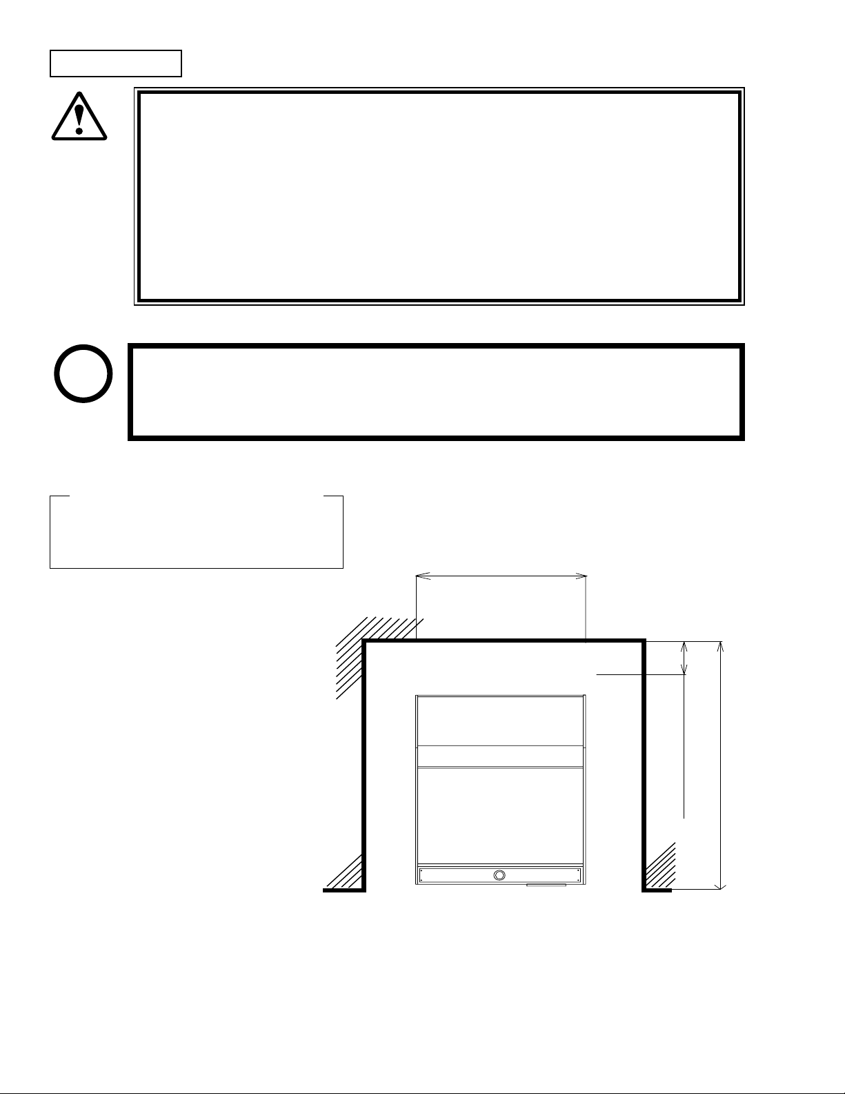
Operation Area
42.25 in.
Vent approx. 8 in.
24.75 in.
For the operation of this machine, secure a minimum area of 24.75 in. (W) ×
WARNING!
Be sure to provide sufcient space so as to allow this product's ventilation fan
SEGA shall not be held responsible for damage, compensation for damage to a
42.25 in. (D). In order to prevent injury resulting from the falling down accident during game play, be sure to secure the minimum area for operation.
to function efciently. To avoid machine malfunctioning and a re, do not
place any obstacles near the ventilation opening.
third party, resulting from the failure to observe this instruction.
STOP
For transporting the machine into the location's building, the minimum necessary
dimensions of the opening (of doors, etc.) are 24.75 in. (W) and 62.5 in. (H).
IMPORTANT!
Electric current consumption
MAX. 4 A (AC 120 V 60 Hz)
www.seuservice.com
4

3. OPERATION
PRECAUTIONS TO BE HEEDED BEFORE STARTING THE OPERATION
To avoid injury and trouble, be sure to constantly give careful attention to the behavior and manner
of the visitors and players.
In order to avoid accidents, check the following before starting the operation:
To ensure maximum safety for the players and the customers, ensure that where
WARNING!
the product is operated has sufcient lighting to allow any warnings to be read.
Operation under insufcient lighting can cause bodily contact with each other,
hitting accident, and or trouble between customers.
It is suggested to ensure a space allowing the players who feel sick while play-
ing the game to take a rest.
Check if all of the adjusters are in contact with the surface. If they are not, the
Cabinet may move and cause an accident.
Ensure that all of the Adjusters are in contact
with the oor.
5
www.seuservice.com

7
www.seuservice.com
Immediately stop such violent acts as hitting and kicking the product. Such
violent acts can cause parts damage or falling down, resulting in injury due to
fragments and falling down.
CAUTION!
Do not put any heavy item on this product. Placing any heavy item on the prod-
uct can cause a falling down accident or parts damage.
WARNING!
PRECAUTIONS TO BE HEEDED DURING OPERATION (PAYING ATTENTION TO CUSTOMERS)
WARNING!
Do not climb on the product. Climbing on the product can cause falling down
accidents. To check the top portion of the product, use a step.
To avoid electric shock, check to see if door & cover parts are damaged or omit-
ted.
To avoid electric shock, short circuit and or parts damage, do not put the follow-
ing items on or in the periphery of the product.
Flower vases, owerpots, cups, water tanks, cosmetics, and receptacles/
containers/vessels containing chemicals and water.
To avoid injury and trouble, be sure to constantly give careful attention to the behavior and manner of the visitors and players.
To avoid injury and accidents, those who fall under the following categories are
not allowed to play the game.
• Those who have experienced muscle convulsion or loss of consciousness when playing video game, etc.
• Intoxicated persons.
• Persons whose act runs counter to the product's warning displays.
To avoid injury resulting from falling down and electric shock due to spilled
drinks, instruct the player not to place heavy items or drinks on the product.
To avoid electric shock and short circuit, do not allow customers to put hands
and ngers or extraneous matter in the openings of the product or small openings in or around the doors.
To avoid falling down and injury resulting from falling down, immediately stop
the customer's leaning against or climbing on the product, etc.
WARNING: HAZARD TO EPILEPTICS.
A very small portion of the population has a condition which may cause them to ex-
WARNING!
If you or anyone in your family has experienced symptoms linked to an epileptic
We recommend that parents observe their children while they play video games. If
www.seuservice.com
perience epileptic seizures or have momentary loss of consciousness when viewing
certain kinds of ashing lights or patterns that are present in our daily environment.
These persons may experience seizures while watching some kinds of television
pictures or playing certain video games. People who have not had any previous
seizures may nonetheless have an undetected epileptic condition.
condition (e.g., seizures or loss of awareness), immediately consult your physician
before using any video games.
you or your child experience the following symptoms: dizziness, altered vision, eye
or muscle twitching, involuntary movements, loss of awareness, disorientation, or
convulsions, DISCONTINUE USE IMMEDIATELY and consult your physician.
6

4. ASSEMBLING AND INSTALLATION
Perform assembly work by following the procedure herein stated. Failing to
comply with the instructions can cause electric shock hazard.
WARNING!
Perform assembling as per this manual. Since this is a complex machine,
erroneous assembling can cause an electric shock, machine damage and or not
functioning as per specied performance.
When assembling, be sure to use more then one person. Depending on the
assembly work, there are some cases in which working by one person alone can
cause personal injury or parts damage.
Ensure that connectors are accurately connected. Incomplete connections can
cause electric shock hazard.
Be careful not to damage the wires. Damaged wires may cause electric shock or
short circuit or present a re risk.
This work should be performed by the Location's Maintenance Man or
Serviceman. Performing work by non-technical personnel can cause a severe
accident such as electric shock. Failing to comply with this instruction can cause
a severe accident such as electric shock to the player during operation.
Provide sufcient space so that assembling can be performed. Performing work
in places with narrow space or low ceiling may cause an accident and assembly
work to be difcult.
To perform work safely and avoid serious accident such as the cabinet's falling
down, do not perform work in places where step-like grade differences, a ditch,
or slope exist.
CAUTION!
Handle molded parts with care. Undue weight or pressure may cause them to
break and the broken pieces may cause injury.
To perform work safely and securely, be sure to prepare a step which is in a
secure and stable condition. Performing work without using the step can cause
violent falling down accidents.
Tools such as a Phillips type screwdriver may be required for the assembly work.
Phillips type screwdriver
7
www.seuservice.com

9
www.seuservice.com
42.25 in.
Vent approx. 8 in.
24.75 in.
FIG. 6. 2 e
Provide ventilation space for the ventilation
opening.
Allow more than 28 in. of space for customer
trafc.
www.seuservice.com
8

POWER SUPPLY, AND EARTH CONNECTION
Be sure to independently use the power supply socket outlet equipped with
WARNING!
Ensure that the "accurately grounded indoor earth terminal" and the earth wire
Ensure that the power cord and earth wire are not exposed on the surface
After wiring power cord on the oor, be sure to protect the power cord. Exposed
an Earth Leakage Breaker. Using a power supply without an Earth Leakage
Breaker can cause a re when electric leakage occurs.
cable are available (except in the case where a power cord plug with earth is
used). If the grounding work is not performed appropriately, customers can be
subjected to an electric shock, and the product's functioning may not be stable.
(passage, etc.). If exposed, they can be caught and are susceptible to damage. If
damaged, the cord and wire can cause electric shock and short circuit accidents.
Ensure that the wiring position is not in the customer's passage way or the wiring
has protective covering.
power cord is susceptible to damage and causes an electric shock accident.
The AC Unit is located inside on one side of Cabinet. The AC Unit has Main SW, Earth Terminal
and the Inlet which connects the Power Cord.
Ensure that the Main SW is OFF.
Power is off when the
MAIN SWitch is in the
down position. To supply
power to the unit, ip the
MAIN SW
MAIN SWitch upwards.
INLET
* Note: Actual Power Supply connection
may vary from photo
AC Cable (Power Cord)
9
www.seuservice.com

11
www.seuservice.com
5. PRECAUTIONS WHEN MOVING THE MACHINE
When moving the machine, be sure to unplug the power plug. Moving the
machine with the plug as is inserted can damage the power cord and cause re
WARNING!
and electric shock hazards.
When moving the machine on the oor, pay careful attention so that adjusters
do not tread power cords and earth wires. Damaging the power cords can cause
electric shock and short circuit hazards.
Do not push the cabinet from the left/right when attempting to move the unit.
Pushing from the sides may cause the unit to tip and result in injury and damage
to parts.
Do not push on any parts made of glass (e.g. Main Plex) or plastic, as these parts
may break and result in bodily injury.
CAUTION!
www.seuservice.com
10

6. NAME OF PARTS
Marquee
Speaker
Play Area
7 Seg. Display
Play Button
Coin Inlet
Prize Chute
TABLE 1 Dimensions and Weights
Width x Length x Height Weight
CABINET 24.75 in x 34.25 in x 62.5 in 210 LBS
11
www.seuservice.com

13
www.seuservice.com
7. GAME DESCRIPTION
The following explanations apply to cases where the product is functioning satisfactorily. Should
there be anything different then the following contents, some sort of faults may have occurred.
Immediately look into the cause of the fault and eliminate the cause thereof to ensure satiffactory
operation.
Connect the Power cord to an A/C source, turn on the power switch, then verify the following:
• A lamp is lit in the Marquee
• Sound is emitted from the speaker below the marquee
• The Prize bucket starts spinning
• The Play button Lights up
• The 7 SEG LED starts it attaction spinning display
Lights up
Sound is emitted
Game Overview
This is a Bulk Vending Product. Meaning the customer inputs money/tokens and recieves a product.
The customer inputs his monies and then Elephant moves his head to attempt to dispense a products
through the Output Chute. The game can be set to play until the customer wins a prize or on a pay
per play basis.
Flashes
Lights up
www.seuservice.com
12

8. HOW TO PLAY
Play starts with the player inserting a coin/
token into a slot on the front of the machine.
When the coin/token is realeased the Elephant
moves his head and “Nose” in an attempt to
aquire a “Prize” for the customer. Depending
of settings on the game board the Elephant
may attempt until a prize is dispenced or stop
after a single attempt.
Insert Coin/Token
If the Elephant is successful in aquireing a
prize for the customer then the prize is now
dispenced though the Prize Chute on the front
of the game.
After Play the Elephant returns to it attract
mode settings.
Elephant attempts for Prize
Prize is dispenced
Returns to Attract Mode
13
www.seuservice.com

15
www.seuservice.com
9. Gameboard Cong Settings
Dip Switches
Dip Switches
SW1
Switch 1 (Play until Prize is won)
On Enable play until prize is won
Off Disable play until prize is won
Switch 2 & 3 (Credits per Play)
Off Off 1 Credit for play amount
Off On 2 Credits for play amount
On Off 3 Credits for play amount
On On 4 Credits for play amount
* If Switch 1 is “On” then Switches 2&3 (Credits per play) are ignored.
Switch 4 & 5 (Coin amount to play)
Off Off $0.25 to play
Off On $0.50 to play
On Off $0.75 to play
On On $1.00 to play
Switch 6 (Attract Mode Sounds)
Off Attract Sounds Off
On Attract Sound On
Switch 7 & 8
Off Off 2 nose notches
Off On 3 nose notches
On Off 4 nose notches
On On 5 nose notches
Note: If large prizes are used, Please adjust Nose Notches to reduce strain when grabbing Objects.
Failure to do so may result in damage.
10. Game Features
Power loss feature:
• If power is lost while in game play, game will resume from where it was interupted.
Nose features:
• Nose cam is manufactured with several notches for nose positioning. This allows
Prizes of different sizes to be used without compromising game-play.
• If the rst notch is not seen by the sensor then the head moves back up to position
and then lowers to retry grabbing prizes
• This retries 3 times then posts an error 4 - nose open / close error indicating a problem
either with the nose motor or the close optical sensor.
www.seuservice.com
14

Optical sensor check sequence:
• On Power up or game resetting for next play the optical sensor status is analyzed.
• If Optical status is not saved for each optical sensor the game will initiate the “Optical
Sensor check sequence” which moves each motor in sequence to test sensor
transitions.
• Order in which sensors are checked:
1) Head will move down and up to test head sensors
2) Body will move to Elephants Left sensor and test transition.
3) Nose will now close to rst nose notch and then open to check open sensor
4) Body will move back to home position and start attract mode until coin is
inserted.
11. Game Errors
Minor Errors: Minor optical sensor errors; does not interferre with game pla or operation.
Minor optical sensors Letter code
- Nose open optical sensor A
- Head down Optical sensor D
- Body Right Optical Sensor F
While in attract mode, display will show the optical sensor letter code if there was a problem.
Major Errors: Motor Errors and Imperative Sensor Errors.
• If an optical sensor is not blocked within the allowed time the game will enter Error mode.
This will stop all motors and lamps and display the error number.
Imperative optical sensors
- Nose close optical sensor
- Head up optical sensor
- Body left optical sensor
- Body home optical sensor
Display will ash “E” “=” “#” (stops game to prevent motor damage if faulty)
# = error encountered
1 = IMPERATIVE OPTICAL SENSOR ERROR
2 = ELEPHANT LEFT/RIGHT MOTOR ERROR
3 = HEAD UP/DOWN MOTOR ERROR
4 = NOSE OPEN/CLOSE MOTOR ERROR
7 = UP / DOWN MOTOR ERROR
9 = LEFT / RIGHT MOTOR REVERSED ERROR
• Press Test button to exit errors and reset game
15
www.seuservice.com

17
www.seuservice.com
12. Test Mode
While the game is playing:
- Press test button once plays a sound but doesn’t affect game play.
- Press and hold test button for 2 seconds stops game-play, clears credits and resets game.
While the game is in attract mode:
- If all sensors are operational and there are no errors
- The display attract show lights every segment in a gure eight order
- If there are sensor problems detected the display will show a letter code corresponding to
the bad optical sensor
• Press Test button once to test lights, optical sensors, prize sensor, and push button.
This enters “Segment display Test mode”
Segments of the Display will light while the corresponding optical sensor is blocked.
- Pressing push button will initiate check optical sensor sequence and then return
to test mode segment display, ashing all segments of bad optical sensors.
- Sements of the Display will ash if there was a problem detected with the
corresponding optical sensor.
A = Nose Open sensor
* B = Nose Close sensor
* C = Head Up sensor
F
D = Head Down sensor
E
* E = Elephant Left sensor
F = Elephant Right sensor
* G = Elephant Home sensor
ALL SEGMENTS = Prize sensor with audible tone
Note: *=Imperative optical sensor
A
B
G
C
D
- Pressing test button again enters Nose Motor Test - Display will read “1”
Nose motor will then move from closed to open until test button, or either volume button
is pressed
- Press Volume Up or Volume Down buttons to initiate manual nose motor movement test
Press Volume Up button to open nose.
Press Volume Down button to close nose.
Note: Optical sensor segments will light when optical sensor is blocked.
- Pressing Test button again enters Head Up / Down Motor Test - Display will read “2”
Head motor will then move from Up to Down until test button or either Volume button is
pressed.
- Press Volume up or Volume Down buttons to initiate manual head motor movement test
Press Volume up botton or Volume down button to move head up and down.
Note: Optical sensor segments will light shen optical sensor is blocked.
- Pressing test again enters the Body Left / Right Motor Test - Display will read “3”
Body Motor will then move left to right and home until test button or either volume
button is pressed
- Press Volume up or Volume down buttons to initiate manual body motor movement test
Press Volume up button to move body to its left.
Press Volume down button to move body to its right.
Note: optical sensor segments will light when optical sensor is blocked
www.seuservice.com
16

13. DESIGN RELATED PARTS
999-1726
Plex Marquee JT
999-1729
Decal Header Left
999-1730
Decal Header Right
999-1738
Glass Front Door
999-1727
Plex Control Panel
999-1739
Plex Right Side
999-1740
Plex Left Side
999-1736
Eyeball SET
999-1731
Decal Cabinet JT Left
999-1732
Decal Cabinet JT Right
999-1728
Decal Game Front
17
www.seuservice.com

19
www.seuservice.com
14. PARTS (Header)
3
4
1
2
Item # Part # Description
1 999-1733 Marquee Sash
2 Local Purchase Fluorescent Fixture 18 in 15 W Coolwhite
3 999-1751 Speaker
4 999-1749 Prize Ramp
www.seuservice.com
18

PARTS (Midheight of Game)
1
9 8
11
10
Item # Part # Description
1 999-1734 Top Sash
5 999-1741 Main Door Hindge
6 999-1742 Main Door Frame
7 999-1735 Bottom Sash Cab
8 999-1743 Rear Door
9 999-1745 Key & Lock Rear Door
10 999-1744 Main Door Key & Lock X2
11 999-1746 Prize Chute Top
5
6
7
19
www.seuservice.com

21
www.seuservice.com
PARTS (Lower Game)
4
5
6
7
2 3
Item # Part # Description
1 999-1752 7 Segment LED
2 999-1753 Leg Adjuster
3 999-1754 Swivel Casters
4 999-1755 SW Playbutton (Flashing)
5 999-1747 Prize Chute Frame
6 999-1748 Prize Chute Lower
7 999-1737 Plex Prize Chute Door
1
www.seuservice.com
20

PARTS (Electronics)
5
1
2
4
4
Item # Part # Description
1 998-0185 Transfomer
2 998-0186 Power Supply
3 998-0187 Line Filter
4 998-0189 Motor Boards
5 998-0188 Main Game Board
3
21
www.seuservice.com

23
www.seuservice.com
PARTS
1
7
8
2
3
4
6
9
Item # Part # Description Notes
1 999-1758 Elephant Trunk
2 999-1756 Elephant Head
3 999-1757 Elephant Torso
4 999-1750 Prize Bucket Side
5 999-1830 Prize Bucket Bottom
6 999-1831 Prize Bucket Mixer/Diverter
7 999-1832 Prize Sensors
8 999-1833 Prize Chute Center
9 999-1834 Nose Tip
10 999-1835 Nose Tip Claw
10
5
www.seuservice.com
22

PARTS
16
7
8
17
6
2
3
4
5
1
Item # Part # Description Notes
1 999-1814 Trunk Tip Mount
2 999-1815 Trunk Channel
3 999-1816 Trunk Band Metal
4 999-1817 Trunk Band Plastic
5 999-1818 Trunk Band Plastic Ribbed
6 999-1819 Trunk Frame
7 999-1820 Trunk Band Bracket
8 999-1821 Trunk Band Mount/Slide
9 999-1822 Trunk Band Arm
10 999-1823 Encoder Wheel 1/2 Trunk
11 999-1824 Trunk/Head Base Bracket
12 999-1825 Shoulder Screw Allen Head 1/8
13 999-1826 Head Cam Arm
14 999-1827 Opto Coupler 1 on each side
15 999-1828 Opto Coupler Bracket Trunk 1 for each Coupler
16 999-1761 Trunk Motor
17 999-1829 Trunk Motor Bracket
13
12
9
15
14
10
11
23
www.seuservice.com

25
www.seuservice.com
PARTS
7
8
1
6
2
3
4
5
2
9
Item # Part # Description Notes
1 999-1841 Head Cam
2 999-1827 Opto Coupler 2 on bracket
3 999-1847 Opto Coupler Bracket Head
4 999-1842 Head Motor Bracket
5 999-1843 Elephant Main Frame
6 999-1759 Head Motor Up/Down Motion
7 999-1844 Elephant Main Post
8 999-1845 Interrupter Opto Bracket
9 999-1846 Opto Coupler Bracket Body 3 of them
www.seuservice.com
24

PARTS
321
7
8
9
4
5
6
10
11
17
16
Item # Part # Description Notes
1 999-1848 Bearing Bracket Visable U Shaped Bracket
2 999-1855 Bearing
3 999-1854 Bearing Holder Flat Plate on Top
4 999-1836 Bucket Shaft and Plate
5 999-1762 Bucket Motor
6 999-1837 Bucket Support Brace
7 999-1838 Shaft Coupler
8 999-1839 Bucket Motor Bracket
9 999-1840 Brace Mount 1 on each side
10 999-1851 Elephant Center Shaft
11 999-1849 Elephant Motor Bracket
12 999-1762 Elephant Motor Side to Side Motion
13 999-1850 Elephant Motor Coupler
14 999-1856 Heavy Bearing
15 999-1852 Elephant Shaft Frame
16 999-1853 Elephant Frame Brace
17 999-1844 Elephant Main Post
15
13 12
14
25
www.seuservice.com

27
www.seuservice.com
15. WIRE COLOR CODE TABLE
THE WIRE COLOR CODE is as follow:
A PINK
B SKY BLUE
C BROWN
D PURPLE
E LIGHT GREEN
Wires other than those of any of the above 5 single colors will be displayed by 2 alphanumeric
characters.
0 NO TRACE
1 RED
2 BLUE
3 YELLOW
4 GREEN
5 WHITE
7 ORANGE
8 BLACK
9 GRAY
If the right-hand side numeral of the code is 0, then the wire will be of a single color shown by
the left-hand side numeral (see the above).
Note 1: If the right-hand side alphanumeric is not 0, that particular wire has a spiral color code.
The left-hand side character shows the base color and the right-hand side one, the spiral
color.
<Example> 51 ……… WHITE / RED
RED WHITE
Note 2: The character following the wire color code indicates the size of the wire.
U: AWG16
K: AWG18
L: AWG20
None: AWG22
www.seuservice.com
26

16. INPUT PORT ASSIGNMENTS
P9 - 34 pos. Ultrex connector
Color Code Pin Bit Access Description
90 A10 BIT 6 Push Button Switch
D0 B10 BIT 7 Test Button Switch
95 A11 BIT 8 Volume Up Switch
93 B11 BIT 9 Volume Down Switch
98 A12 BIT 10 Coin Switch
D1 B12 BIT 11 Nose Open Sensor
D2 A13 BIT 12 Nose Close Sensor
71 B13 BIT 13 Elephant Left Sensor
72 A14 BIT 14 Elephant Home Sensor
78 B14 BIT 15 Elephant Right Sensor
51 A15 BIT 16 Head Up Sensor
52 B15 BIT 17 Head Down Sensor
58 A16 BIT 18 Bucket Turn Sensor
53 B16 BIT 19 Prize Sensor
5D B17 BIT 20 Meter Current Sensing
17. OUTPUT PORT ASSIGNMENTS
P9(I/O) - 34 pos. Ultrex connector
Color Code Pin Bit Access Description
20 A1 OUTPORT 6 BIT 0 Left Motor
28 B1 OUTPORT 6 BIT 1 Right Motor
21 A2 OUTPORT 6 BIT 2 Up Motor
23 B2 OUTPORT 6 BIT 3 Down Motor
24 A3 OUTPORT 6 BIT 4 Open Motor
2D B3 OUTPORT 6 BIT 5 Close Motor
DC A4 OUTPORT 6 BIT 6 Ears Motor
29 A5 OUTPORT 6 BIT 8 Disable Motors
5D B5 OUTPORT 6 BIT 9 Prize Meter
59 A6 OUTPORT 6 BIT 10 Coin Meter
97 B6 OUTPORT 6 BIT 11 Coin Lock
P4(Multiplexed Lamp Sinks) - 18 pos. KK-100 connector
Color Code Pin Bit Access Description
5C 1 LC0 Button Lamp Sink
3D 2 LC1 Bin 1 Lamp Sink
37 3 LC2 Bin 2 Lamp Sink
39 4 LC3 Eye 1 Lamp Sink
35 5 LC4 Eye 2 Lamp Sink
6 LC5 Button Lamp Sink Backup
7 LC6 Bin 1 Lamp Sink Backup
8 LC7 Bin 2 lamp Sink Backup
9 LC8 Eye 1 Lamp Sink Backup
10 LC9 Eye 2 Lamp Sink Backup
27
www.seuservice.com

P6(Multiplexed Lamp Source) - 16 pos. KK-100 connector
Color Code Pin Bit Access Description
3C 1 BIT 1 Button lamp Source
31 2 BIT 2 Bin 1 Lamp Source
34 3 BIT 3 Bin 2 Lamp Source
32 4 BIT 4 Eye 1 Lamp Source
38 5 BIT 5 Eye 2 Lamp Source
6 BIT 6 Button Lamp Source Backup
7 BIT 7 Bin 1 Lamp Source Backup
8 BIT 8 Bin 2 Lamp Source Backup
9 BIT 9 Eye 1 Lamp Source Backup
10 BIT 10 Eye 2 Lamp Source Backup
P10(Loudspeakers) - 5 pos. KK-100 connector
Color Code Pin Name Description
D0 1 LS1+ Channel 1 Jumper
D0 3 MIX Channel 2 mixed input
D5 4 LS2+ Channel 2
D3 5 LS2- Channel 2
P5(Multiplexed L.E.D.’s) - 32 pos. Ultrex connector
Color Code Pin Bit Access Description
40 A1 DIGIT 0 Common Cathode
41 A9 SEG 0 Segment 0
42 B9 SEG 1 Segment 1
47 A10 SEG 2 Segment 2
4C B10 SEG 3 Segment 3
48 A11 SEG 4 Segment 4
4D B11 SEG 5 Segment 5
45 A12 SEG 6 Segment 6
www.seuservice.com
28

Warranty
Your new Sega Product is covered for a period of 90 days from the date of shipment. This certies
that the Printed Circuit Boards, Power Supplies and Monitor are to be free of defects in workmanship or materials under normal operating conditions. This also certies that all Interactive Control
Assemblies are to be free from defects in workmanship and materials under normal operating conditions. No other product in this machine is hereby covered.
Sellers sole liability in the event a warranted part described above fails shall be, at its option, to replace or repair the defective part during the warranty period. For Warranty claims, contact your Sega
Distributor.
Should the Seller determine, by inspection that the product was caused by Accident, Misuse, Neglect, Alteration, Improper Repair, Installation or Testing, the warranty offered will be null and void.
Under no circumstances is the Seller responsible for any loss of prots, loss of use, or other damages.
This shall be the exclusive written Warranty of the original purchaser expressed in lieu of all other
warranties expressed or implied. Under no circumstance shall it extend beyond the period of time
listed above.

SEGA AMUSEMENTS USA, INC.
 Loading...