


GL-1 Gate Lock
Installation Instructions and
Operating Manual
1
500-22090, Rev A
Table of Contents |
|
Table of Contents.............................................................................................. |
2 |
Specifications..................................................................................................... |
3 |
Physical .......................................................................................................... |
3 |
Electrical......................................................................................................... |
3 |
Product Overview.............................................................................................. |
3 |
Product Features:..................................................................................... |
3 |
Product Components........................................................................................ |
4 |
Recommended Tools........................................................................................ |
4 |
Installing the GL1 Electromechanical Gate Lock.......................................... |
5 |
Perform a Pre-Installation Survey .............................................................. |
5 |
Perform the Cylinder Lock/Cover Hole Plug Installation......................... |
8 |
Mount the GL1 and Connect the Electrical ............................................. |
10 |
Complete the GL1 Installation................................................................... |
13 |
Operating Instructions .................................................................................... |
13 |
Troubleshooting............................................................................................... |
14 |
MagnaCare® Lifetime Replacement Warranty............................................ |
15 |
2
500-22090, Rev A
Specifications
Physical
Holding Force |
2,000 lbs [907 kg] |
Preload |
Up to 100 lbs (Fail Locked only) |
Dimensions |
2 ¾” L X 7 ¼” H X 3 ¼” D |
|
[70 mm L X 184 mm H X 83 mm D] |
Electrical |
|
12 VDC Current Requirement |
Initial (Peak): 870 mA (~ 1 sec) |
|
Reduced: 290 mA |
|
Power Consumption: 3.5 Watts |
24 VDC Current Requirement |
Initial (Peak): 720 mA (~ 1 sec) |
|
Reduced: 170 mA |
|
Power Consumption: 4.1 Watts |
Operating Temperature |
–58 to +167 F [–50 to +75 C] |
|
° ° |
Product Overview
The GL1 Electromechanical Gate Lock is designed to secure a wide variety of vehicle and pedestrian gate applications where security and weather resistance are required. The GL1 functions equally well in both electrically and manually operated gate installations and can be used for swing gates, sliding gates, stock cage gates or other applications.
Product Features:
•2000 lbs holding force
•Operates under preload up to 100 lbs.
•Automatic dual voltage—no field adjustment required
•Manual key override (right or left hand)—Fail Locked only
3
500-22090, Rev A
•Self-aligning receiver (up to +/- 1/2" horizontally or vertically) helps compensate for gate misalignment and sag
•Tamper proof cast housing
•Latch status monitor switch (SPDT)
•½”-14 NPSM inside pipe thread
•Surface Mount
•Black finish
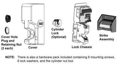
Product Components
Upon unpacking this product, an inventory should be made to ensure that all the required components and hardware have been included. Along with these instructions and the installation template, the lock assembly should include the following items:
Recommended Tools
Hammer |
Screwdriver, #2 Phillips |
Center Punch |
Hex (Allen) wrench, 3/16” [5 mm] |
Drill Bits: 5/16”, 3/8”, ½” |
Tap, ¼”-20 UNC [M6-1.0] |
4
500-22090, Rev A
Installing the GL1 Electromechanical
Gate Lock
Installation Concerns
CAUTION: |
It is vital that all welding be completed prior to |
|
making any electrical connections to the mounted |
|
GL1. Welding in or around an electrically-connected |
|
lock assembly can cause damage to the electronic |
|
components. |
•Installation should be performed by a qualified service person, who conforms to all local codes and complies with The National Electrical Code (or equivalent).
•The FMK-SL (Sliding Gate) and the FMK-SW (Swing Gate) mounting bracket kits are recommended for installing the GL1.
•The GL1 must be mounted in the upright vertical position with the conduit opening on the bottom.
•The GL1 should not be used for dual swing gates.
Perform a Pre-Installation Survey
Due to the variety of mounting configurations available with this product, it is strongly recommended that an initial physical survey and assessment be made of the actual area where the lock will be installed to determine the optimal method of mounting prior to installation. The following should be considered:
•Physical strength of mounting areas: It is recommended that the structural integrity of mounting surfaces be strong enough to meet or exceed the holding force of the lock.
•Protection of the lock from external attack: The lock and the wiring must be protected to a reasonable degree from potential damage due to intruders or vandals.
•Convenience and accessibility of area to be protected: The lock
5
500-22090, Rev A
 Loading...