Securitron EEB2, EEB3N Installation Instructions

Securitron
10027 S. 51st St., Ste. 102, Phoenix, AZ 85044 Tel: 1.800.624.5625
Mon-Fri: 6:00am - 4:00pm PDT techsupport@securitron.com www.securitron.com
SECURITRON EEB2, EEB3N EXIT BUTTON WITH INTEGRATED TIMER
INSTALLATION AND OPERATING INSTRUCTIONS
DESCRIPTION
Model EEB2 is a two-inch square, exit button, mounted on a stainless steel (S.S.), single gang key plate. Model EEB3N is a rectangular exit button, mounted on a 1 3/4” S.S. narrow stile key plate. Both EEB2 and EEB3N have a 3A switching capacity and a timer set for 30 seconds. These units are intended only for release of a magnetic lock from the inside of a door. When the button is pressed, the lock releases for 30 seconds. If pressed again during the 30-second lock release period, the unit will “retrigger” starting a new 30-second lock release period. These buttons are specifically intended for installation on access controlled egress doors, as described in the Building Officials and Code Administrators (BOCA) code. A motion detector, such as the Securitron Model XMS, is the primary means of magnetic lock release on the door. The EEB2 or EEB3N exit button is employed as a backup means of releasing the lock in case of a problem with the motion detector. It should be noted that the exact release time will vary with temperature, but it will not be less than 30 seconds.
UL294 ACCESS CONTROL PERFORMANCE LEVELS
The following are the UL294 access control performance levels:
•Destructive Attack = Level 1
•Line Security = Level 1
•Endurance = Level 1 (6,000 cycles)
•Standby Power = Level 1
MOUNTING THE EEB2 AND EEB3N EXIT BUTTONS
1. MOUNT the EEB2 using its included mounting device.
NOTE: The aluminum door frame must be sufficiently routed out to accommodate the EEB3N components. 2. MOUNT the EEB3N directly on a narrow stile aluminum door frame.
WIRING THE EEB2 AND EEB3N
CAUTION
THE EEB2 and EEB3N can be damaged if operated on 24 VDC with the jumper in place, or operated on a power supply different than what is operating the magnetic lock.
NOTE 1: The EEB2 and EEB3N operate on 12 VDC or 24 VDC, and can accept the use of full-wave rectified DC (transformer and bridge rectifier).
NOTE 2: EEB2 and EEB3N are factory shipped with the jumper in place (12 VDC). If jumper is removed, unit operates on 24 VDC.
NOTE 3: EEB2 and EEB3N draw no current when at rest, and only draw 28 mA at 12 VDC or 38 mA at 24VDC when releasing the lock.
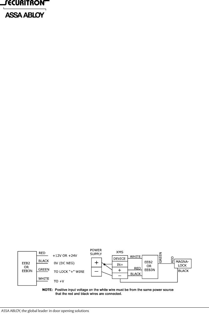
1.WIRE the EEB2 or EEB3N in accordance with Figure 1, “Wire Identification and Typical Connection,” and Figure 2, “Internal Schematic.”
Figure 1. Wire Identification and Typical Connection
|
PN# 500-12600 |
Page 1 |
Rev. F, 01/15 |
 Loading...