

Page 1
Digital Access Keypad Manual
User Operation for the SK-1011-SQ
1. Using the User Codes:
A. User codes operate the door (4-8 digits long).
B. The key must also be pressed if he keypad is in manual-entry mode.
2. Using the Master Code:
The Master Code can be used to operate the door or program the keypad
(4-8 digits long, see pt. 4 below).
A. To operate the relay output:
B. Inhibit/lockout code:
3. Using the Inhibit/Lockout Code:
A. Inhibit/lockout codes temporarily lock the keypad. (4-8 digits long, see pg. 5 for more information)
B. The key must be pressed also if he keypad is in manual-entry mode.
4. User Code and Master Code Programming:
A. Enter the Master Code first, followed by the key
B. Change/Add/Delete User or Master Codes:
C. Deleting Individual Users:
D. Changing the Master Code:
E. To exit programming mode, press the key.
u u u u
Press
#
u u u u
Press
X X X X
Press
X X X X
Press
n n n n
Press
#
n n n n
Press
(If you forgot the master code, see page 7 for more information.)
X X X X
Press
1
Press 00-99 (user ID) (user code, 4-8 digits)
Press 00-99 (user ID)
1
Press
0
X X X X
#
#
1
#
2
#
*
*
u u u u
#
#
*
#
Note: indicates
the inhibit code.
Note: indicates
the user code.
Note: indicates
the master code.
n n n n
u u u u
X X X X
®
ENFORCER
SK-1011-SQ
Digital Access Keypad
with 5A Relay Output
MANUAL
LIFETIME LIMITED WARRANTY
used in normal service for the lifetime of the product. SECO-LARM’s obligation is limited to the repair or replacement of any defective part
if the unit is returned, transportation prepaid, to SECO-LARM. Under no circumstances will SECO-LARM be responsible for any costs or
charges for removal, installation, or reinstallation. This Warranty is void if damage is caused by or attributed to acts of God, physical or
electrical misuse or abuse, neglect, repair, or alteration, improper or abnormal usage, or faulty installation, or if for any other reason
SECO-LARM determines that such equipment is not operating properly as a result of causes other than defects in material and
workmanship. The sole obligation of SECO-LARM, and the purchaser’s exclusive remedy, shall be limited to repair or replacement only, at
SECO-LARM’s option. In no event shall SECO-LARM be liable for any special, collateral, incidental, or consequential personal or property
damages of any kind to the purchaser or anyone else. This lifetime limited warranty is for products sold and installed in the United States
and Canada. For all other countries the warranty is 1 (one) year.
NOTICE:
policy is one of continual development and improvement. For this reason, SECO-LARM reserves the right to change specifications without
notice. SECO-LARM is also not responsible for misprints or typographical errors. Copyright © 2010 SECO-LARM U.S.A., Inc. All rights
reserved. This material may not be reproduced or copied, in whole or in part, without the written permission of SECO-LARM.
The information and specifications printed in this manual are current at the time of publication. However, the SECO-LARM
This SECO-LARM product is warranted against defects in material and workmanship while
SECO-LARM® U.S.A., Inc.
16842 Millikan Avenue, Irvine, CA 92606
Tel: 800-662-0800 / 949-261-2999 Fax: 949-261-7326
Website: www.seco-larm.com
@
E-mail: sales
seco-larm.com
®
PIHAK1
MiSK-1011-SQ_092810.pmd
SECO-LARM U.S.A., Inc.
Page 8
Also available from SECO-LARM:
Indoor Keypad
SK-1131-SQ SK-2323-SDQ
SECO-LARM
Note: Model numbers that end with "Q" or that have a round green "Q" sticker signify RoHS-compliant products.
SK-1123-SQ
®®
Outdoor Keypads
SK-1123-FQ
SK-1323-SDQ
Page 2
Digital Access Keypad Manual
Digital Access Keypad Manual
T ABLE OF CONTENTS
Introduction................................................................................................................ 2
Unique features ......................................................................................................... 2
Specifications ............................................................................................................ 3
--
Wiring
sample installation..................................................................................... 3
Preparing to program the keypad ............................................................................. 4
Getting started ........................................................................................................... 4
Programming notes .................................................................................................. 4
User programming..................................................................................................... 5
Buzzer and LED signals ............................................................................................ 5
LED indicators ........................................................................................................... 5
Installer programming ............................................................................................... 6
User code worksheet................................................................................................. 6
Reprogram the keypad (certain data) ....................................................................... 7
Reprogram the keypad (complete data refresh)....................................................... 7
Delete user ................................................................................................................ 7
Master code bypass (DAP jumper) ........................................................................... 7
User operation ........................................................................................................... 8
INTRODUCTION
The SK-1011-SQ is the ideal keypad for office, commercial, and home security installations. This selfcontained security keypad has a built-in 5-Amp relay output for maximum flexibility when connecting to
electronic door strikes, door alarms, door chimes, alarm control panels, or other security and access control
applications. The output can be programmed for timed (1-999 seconds) or ON/OFF operation.
The SK-1011-SQ output can be programmed for up to 100 4-digit to 8-digit user codes. All programming and
code information is stored in non-volatile EEPROM memory to protect the data in case of power loss.
UNIQUE FEATURES
•
12-24V AC/DC universal power -- No programming or jumpers needed.
•
Relay output inhibit control / lockout mode --
The relay output is typically used for a door strike. If the
keypad is set to the "inhibited" mode, the relay output will not operate. This increases the security of the
protected premises during the time it is not expected to be occupied, such as during evening or weekend
•
Auto or manual code entry checking:
o
Auto code entry checking mode -- When all the user codes have the same number of digits, the
hours.
keypad will activate automatically when the code is entered. There is no need to press the "#" key.
This is convenient for the users.
o Manual code entry checking mode -- The user codes can vary in
number of digits, and the user must press
the "#" key when finished entering the code. This increases security.
•
Easily delete user codes -- The administrator can delete individual codes without knowing them.
REPROGRAM THE KEYPAD (CERTAIN DATA)
To change certain data in the keypad (such as to delete or change user codes), do the following:
1. Enter program mode by keying in the master code and the key:
X X X X
The keypad is now in the programming mode.
*
*
2. Make any changes to the keypad's data as noted in the various programming instructions.
3. Exit the programming mode by pressing the key.
*
REPROGRAM THE KEYPAD (COMPLETE DATA REFRESH)
Sometimes it may be necessary to completely erase all current data (except the master code) and input new data. An
example of when this may be necessary is the sale of a protected building to a new owner. In such a situation, do the
following:
1. Enter the programming mode by keying in the master code and the key, then enter the refresh code,
#
and the key:
X X X X
8 9 0 1 #
The keypad is now in the programming mode.
*
All old data is cleared, and the keypad is ready for new data.*
*
8 9 0 1
NOTE: The master code does NOT change.
2. Use the programming instructions on page 5 to enter the keypad's data.
3. Exit the programming mode by pressing the key.
*
DELETE USER
T o delete a user who has left the company or who no longer has authority t o enter the protected area:
1. Enter program mode by keying in the master code and the
X X
X X
2. Enter the output # and user ID number and the key:
To delete user ID 05, press
3. Exit the programming mode by pressing the key
The keypad is now in the programming mode.
*
1 0 5 #
#
*
*
key:
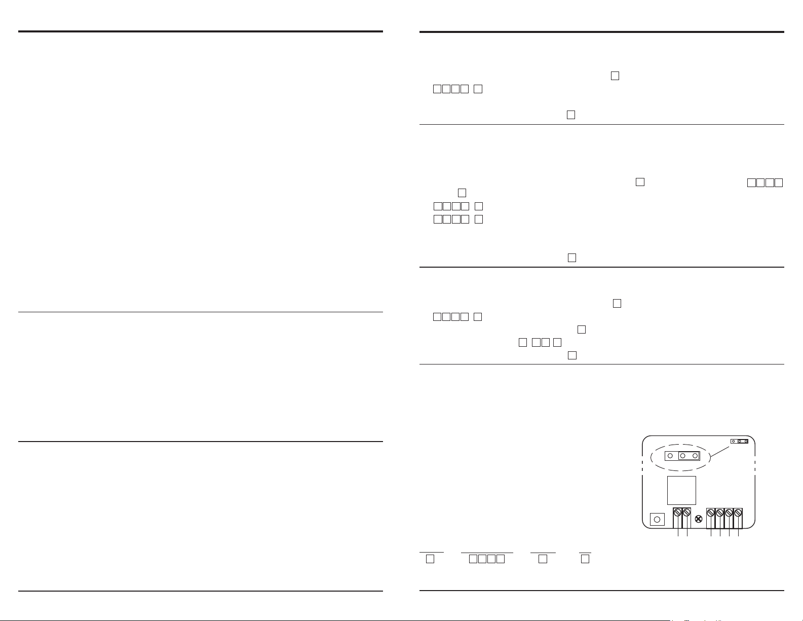
MASTER CODE BYPASS (DAP jumper)
If the master code is forgotten or does not work, use the DAP (direct access to program) jumper to override the forgotten
code and permit direct entry into the programming mode as follows:
1. Disconnect the power supply.
2. Move the DAP jumper from OFF to ON.
3. Reconnect the power supply. The keypad will start beeping.
4. Move the DAP jumper back to the OFF position. The keypad will
stop beeping as soon as the jumper is removed.
DAP
ON OFF
DAP
5. The keypad is now in the programming mode, ready to receive
new programming data.
6. Re-program the keypad as shown starting on page 5.
NOTE -- A new master code may be programmed to replace the one
Relay
Tamp
that was lost or forgotten. Note that the sequence for replacing the old
master code is as follows:
Option*
0 X X
*Zero "0" is for new master code only; see page 5 or 6 for other options.
Key in new code ExitConfirm
X X
#
*
(+) AC/DC
(
-
) AC/DC
N.C.
N.O.
C.
EG In - Egress
SECO-LARM U.S.A., Inc.
Page 7Page 2
Page 3

Digital Access Keypad Manual
Digital Access Keypad Manual
INSTALLER PROGRAMMING
These functions should only be used by professional installers, as incorrect entries can disable the entire keypad function.
Enter Programming Mode
Enter Master code
*
X X X X
*Key in the Master Code.
Note: For first-time use, Master code is
Data Refresh
Op ion Confirm Function
8 9 0 1
Configure Relay Outputs
Option Output ime
4 0
4 1
Relay Output Inhibit Control (lockout mode)
Option Code Entry
5 0
5 1
Wrong Code Lockout
Option
7 0
7 2
7 6 0 0
Door Unlocked Announcer
Option Code entry
8 1
User Code Entry Mode
Op ion Code entry
8 2
Keypress Beeps
Op ion Code entry
8 3
LED Flashes in Standby Mode
8 4
Exit Programming Mode
Confirm
*
#
1 to 999
1 to 999
# of tries
5 to 10
1
{
0
1
0
{
1
{
0
Code entry
1
{
0
Function
Exits programming mode, returns keypad to normal operations
Confirm
*
0 0 0 0
Clears all previously stored data.
Function
Relay momentary mode, from 1 to 999 seconds
#
Relay shunt mode (ON/OFF)
#
Function
Lockout for 1 to 999 seconds
#
Lockout shunt mode (ON/OFF)
#
Function
After 10 successive wrong codes, 30-second lockout
After 5 to 10 wrong codes, 15-min. lockout - Can reset wi h Master Code
None of the above
Function
1-sec. beep notifies the user to open the door when the output relay is ac ivated.
The beep is disabled, replaced by 2 short beeps for valid user codes.
Function
Auto Entry Mode is selected. The key that follows he user code is NOT required in
code entry. The User Codes MUST be set to the same digit length as the Master Code.
Manual Entry Mode is selected. The key that follows the user code is required in
code entry. The User Codes can be 4-8 digits, but not necessarily all of the same length.
Function
Keypad beeps when a key is pressed.
Silent operation -- keypad does not beep when a key is pressed.
Function
Amber LED ON during standby mode.
Amber LED OFF during standby mode.
Confirm
#
#
Confirm
#
#
Confirm
#
#
Confirm
#
#
Confirm
#
#
Confirm
Confirm
Func ion
(DEFAULT: )
Enter into programming mode
(DEFAULT : Moment ary, 1-sec. output)
(DEFAULT : Moment ary, 1-sec. output)
(DEFAULT: 10 tries / 30 seconds)
(DEFAUL T: Manual)
#
#
0 0 0 0
(DEFAULT : On)
(DEFAULT : On)
(DEFAULT : On)
USER CODE WORKSHEET
To print out a blank worksheet where all user codes
can be recorded, please visit www.seco-larm.com
and select the Model #, "SK-1011-SQ" in the drop
down menu for the burglar section. On the product
page click on "User Code Worksheet," which will
load the .PDF.
SPECIFICATIONS:
Power:
• Operation voltage
• Stand-by current drain
• Active current drain (press keypad key)
--
12-24 Volts AC/DC. No jumper needed to set voltage.
--
10mA @12VDC.
--
Under 30mA.
• Active current drain (relay activated) -- Under 80mA.
Outputs:
--
• Relay output
5A @ 28VDC, Form "C", N.O./C./N.C., programmable for 1 to 999 second timed output or
shunt (start/stop) output. Three terminals.
• Tamper output
--
50Ma @12VDC, N.C. output. Connect to tamper circuit of alarm control panel.
Two terminals.
Inputs:
--
• Power
• Egress
12-24Volts AC/DC. Two terminals.
--
N.O., ground (-). Single terminal.
Code Operation:
• Up to 100 user codes, 10,000 possible user code combinations.
• Max. 10 seconds to enter each digit.
• Max. 30 seconds to enter each code.
Dimensions (keypad with back box):
• 4-5/8" x 2-7/8" x 1-7/8" (117 x 74 x 48 mm).
Weight (keypad with back box):
• 6.3 oz. (180 grams).
WIRING (SAMPLE INST ALLATION):
(--)
Tamper
N.C.
Connect to the N.C.
24hr. zone of alarm
panel or other
signalling device.
(+)
12~24V AC/DC
--
+
12VDC
power
supply
Diode
1N4004
+
Cathode
Egress button (inside the
protected premises)
N.C.
Electric
Lock
(for DC
use only)
OUTPUT 1
(+)
N.C.
--
EG
C.
N.O.
N.O.
OR
REMARKS:
Output relay
N.O. output for fail-secure lock.
N.C. output for fail-safe lock.
N.O.
Additional egress buttons
can be connected in parallel
N.O.
as needed
SECO-LARM U.S.A., Inc.
Page 3Page 6
Page 4

Digital Access Keypad Manual
Digital Access Keypad Manual
PREPARING TO PROGRAM THE KEYPAD
Before programing the SK-1011-SQ, you will need to first determine the following information:
1. The master code -- Allows the system administrator to program or operate the keypad.
2. The user code or codes -- Allows users to use the keypad's functions.
3. The inhibit/lockout code -- When inputted, prevents the relay from operating even if a correct user code
is inputted.
4. Configuration of the relay output -- Determine whether the output should operate from 1 to 999 seconds
and then turn OFF (momentary mode), or turns ON/OFF via the code (shunt mode).
5. Result of improper code entry -- Choose between a 30-second code lockout, duress output, a 15-minute
code lockout, or no reaction.
GETTING STARTED
A master code is required to program the keypad. The default master code is set to "0000." To change the
master code, go to page 7 and follow the instructions for "MASTER CODE BYPASS (DAP jumper)."
Once the master code is set, review the programming options and decide exactly what the keypad will do,
including the format of the user access codes as well as how the keypad responds via the relay output,
buzzer and LEDs. Note that in every case the basic steps for programming are:
1. Enter the master code, followed by the key, which puts you in programming mode.
2. Enter the programming codes defined in the various sections as needed, followed by the key.
3. Enter the key again to exit the programming mode.
*
*
#
Note: A rapid string of 5 beeps and/or 5 LED flashes indicates an error, while 2 beeps indicates that the
entry has been accepted.
PROGRAMMING NOTES
1. Master code: The SK-1011-SQ comes pre-programmed with the Master Code set at 0000. Additional
codes and/or data should be programmed at the owner's discretion. However, to ensure security,
program a new personal Master Code to replace the factory-set Master Code as soon as possible.
2. Factory defaults:
Master code 0000
_________________________________________________________________________
User code length 4 to 8 digits
_________________________________________________________________________
Main relay output time 1 second
_________________________________________________________________________
Wrong code lockout 10 tries / 30 second
_________________________________________________________________________
Output activation announcer ON
_________________________________________________________________________
User code entry mode Manual
_________________________________________________________________________
Keypress beep ON
_______________________________________________________________________
Silent operation OFF
3. Code operation: User codes are each four to eight digits and are assigned to two-digit IDs. If all the
codes have the same number of digits, the keypad can be programmed for whether the key must be
#
used or not after entering the code (see programming, option 820 or 821, page 6).
The administrator can easily delete the code of one user via the two-digit ID, if the user is no longer
authorized to enter a protected area, without the need to teach the new code to all the other users.
USER PROGRAMMING
Enter Programming Mode
Enter Master code
X X X X
X X X X
Note: indicates the Master code.
Note: For first-time use, Master code is "0000".
Adding Or Changing Master And User Codes
Op ion
Delete A User
To delete a user who has left the company or who no longer has authority to enter the protected area:
Set Inhibit / Lockout Code (see page 2)
User ID
0
1
00 to 99
Note: No user code can be the same code as the master code or the inhibit/lockout code.
1. Enter Programming Mode:
Enter Master code Confirm
X X X X
2. Delete code
Option
1
1. Enter Programming Mode:
Enter Master code Confirm
X X X X
2. Set code
Option
21
User ID
00 to 99
Access code
4 to 8 digits
Confirm
*
Access code
4 to 8 digits
4 to 8 digits
*
Confirm
#
*
Function
Enter into programming mode
Confirm
Function
Enter into programming mode
Function
Deletes specific user ID
Confirm
#
Function
Master Code
#
Add or change up to 100 User Codes
#
Function
Enter into programming mode
Function
Sets inhibit/lockout code
EXIT
PROGRAMMING
MODE BY PRESSING
lockout duration,
BUZZER AND LED SIGNALS
The keypad's built-in buzzer and the auxiliary red/green LED can signal the following:
_____________________________________________________________________________________
1. In programming mode
_____________________________________________________________________________________
2. Successful key entry
_____________________________________________________________________________________
3. Successful code entry
_____________________________________________________________________________________
4. Unsuccessful code entry
_____________________________________________________________________________________
5. DAP jumper not replaced
_____________________________________________________________________________________
6. In standby mode
_____________________________________________________________________________________
Status
7. Output relay activated
NOTE: * The buzzer can be disabled through programming option 83, ref. pg. 6.
** The output relay activated beep can be disabled through programming option 81, ref. pg. 6.
LED INDICAT ORS
●
Red LED -- Indicates that the door lock output has been inhibited.
●
Amber LED -- Flashes to show the keypad status (see above).
●
Green LED -- Lights while any output is activated.
Buzzer Tones*
N/A
1 beep
2 beeps
5 beeps
Continuous beeps
N/A
1-sec. long beep**
Amber LED Flashes
ON
1 flash
2 flashes
5 flashes
Continuous flashes
1 flash in 2-sec. intervals
N/A
Amber
Red
EXIT THE
THE KEY
*
Note: to set
see page 6
Green
1 2 3
4 5 6
7 8 9
0 #
*
ENFORCER
SECO-LARM U.S.A., Inc.
Page 5Page 4
Page 5

Access Code
00 SAMPLE - John Doe 543215051525354555657585960616263646566676869707172737475767778798081828384858687888990919293949596979899
USER ID User Name
Output: Shunt / Momentary (____secs.) Programmed For__________________________________
00 SAMPLE - John Doe 543210001020304050607080910111213141516171819202122232425262728293031323334353637383940414243444546474849
SK-1011-SQ - User Control Chart
USER ID User Name Access Code
Relay Output #1:
Note: copy this sheet to use for your installations.
 Loading...