

Page 1
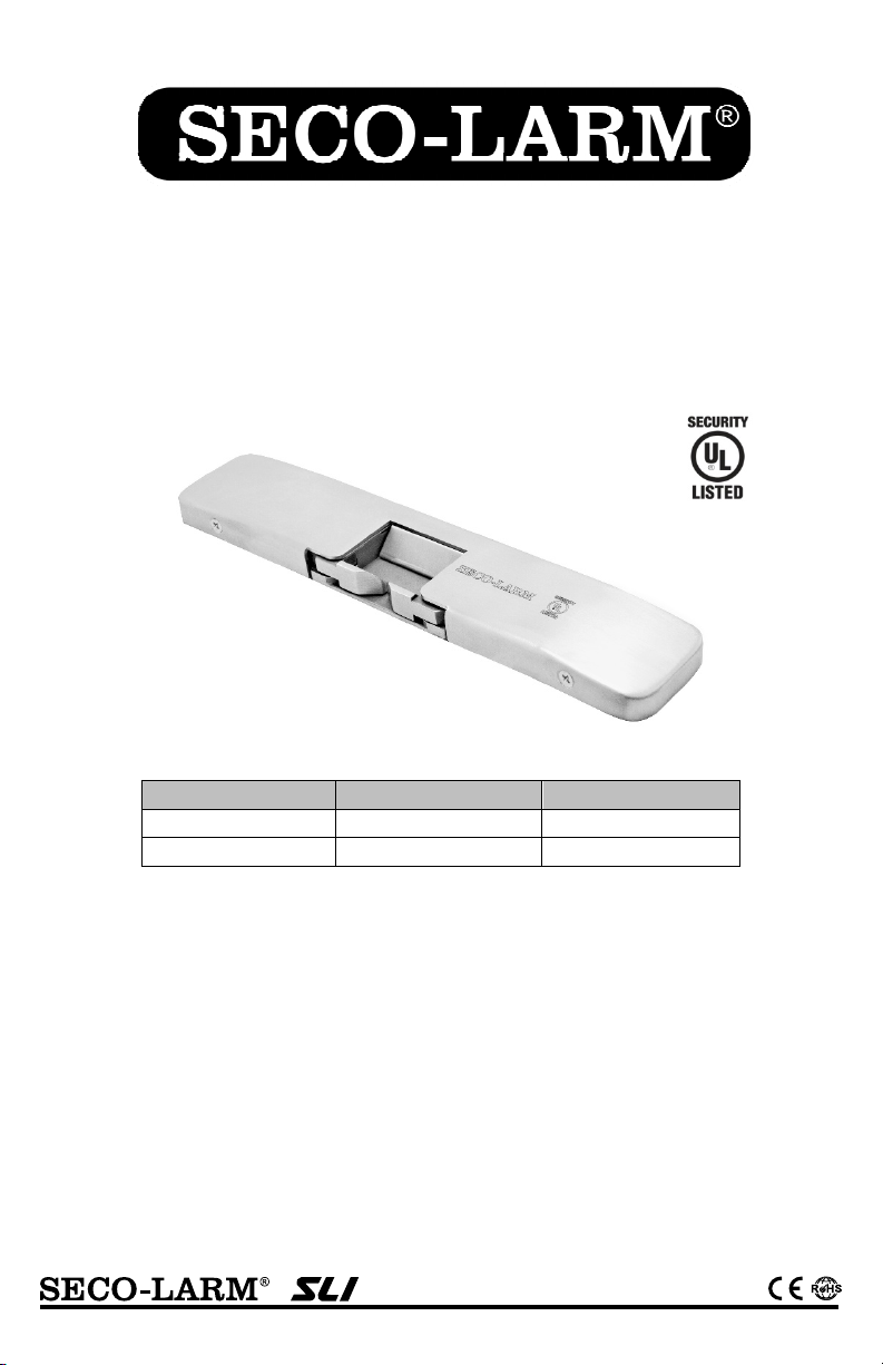
SD-998C-D3Q / SD-998C-D3AQ
Surface-Mount Electric Rim Strikes
Manual
43RG
Model # Housing Thickness Latch Throw
SD-998C-D3Q
SD-998C-D3AQ
Features:
12/24 VDC Operating voltage
Non-polarized connection
Horizontal adjustment
Accommodates up to
Reversible non-handed design fits either
right-hand or left-handed doors
Surface-mount on metal or wood frames
Works with standard rim-type exit devices
including SECO-LARM SD-962AR-36A
and SD-962AR-36G
For Indoor Use Only
3
/4" Pullman latch
SD-998C-D3AQ shown
3
/4" (19mm)
1
/2" (13mm)
Static strength – 1,500-lb (6673N)
Tested for 250,000 cycles (UL Tested)
Low current draw: 540mA@12VDC,
270mA@ 24VDC
Field-selectable for fail-safe or fail-secure operation
The SD-998C series is intended to be used with UL
Listed Exit Hardware
The SD-998C series shall not impair the intended
operation of an emergency unit
The SD-998C series shall not impair the operation
of panic hardware mounted on the door
3
/4" (19mm)
1
/2" (13mm)
Page 2
SECO-LARM Surface-Mount Electric Rim Strikes
A
Introduction:
The SECO-LARM Surface-Mount Electric Rim Strikes are designed with the strength and durability for use
with rim-type exit devices with a Pullman latch bolt (3/4" throw for the SD-998C-D3Q, 1/2" throw for the
SD-998C-D3AQ). The strikes feature 12/24 VDC operating voltage, selectable fail-safe/fail-secure operation,
horizontal adjustment, and a surface-mount metal housing, eliminating the need for frame cutting during
installation.
Parts List:
1x Strike 2x Crimp connectors
1x Blind nut kit 1x Dead latch ramp adapter
2x Blind nuts 1x 12VDC cable connector
1x Hex wrench 1x 24VDC cable connector
2x Hex socket head cap screws Spacers –
2x Philips flat head screws 3x
1x Manual 1x
*SD-998C-D3Q only
**SD-998C-D3AQ only
1
/32" (0.9mm)*
1
/16", 2x 1/8" (1.5mm, 3mm)**
Note: Not all parts will be used in every installation.
Specifications:
Model
Operating voltage 12/24 VDC
Current draw 540mA@12VDC, 270mA@24VDC
Maximum latch throw
Static strength 1,500-lb (6673N)
Dynamic strength 70ft-lb (95J)
Endurance 250,000 cycles (UL Tested), Level IV
Destructive attack Level I
Line security Level I
Standby power Level I
Operating temperature 14°~120° F (-10°~49° C)
Operating humidity
Dimensions 9"x13/4"x3/4" (229x45x19 mm) 9"x13/4"x1/2" (229x45x13 mm)
SD-998C-D3Q SD-998C-D3AQ
3
/4" (19mm)
1
/2" (13mm)
0~85%
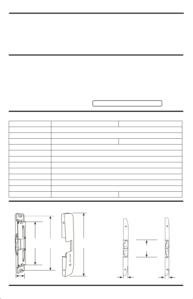
Overview:
SD-998C-D3Q
SD-998C-D3
Q
63/8"
(162mm)
13/4" (45mm)
81/4"
(210mm)
Cover
9"
(229mm)
3
/4"(19mm)
11/2" (38mm)
1
/2"(13mm)
2 SECO-LARM U.S.A., Inc.
Page 3

SECO-LARM Surface-Mount Electric Rim Strikes
Installation:
1. Set either fail-safe or fail-secure operation. See "Selecting
Fail-Safe/Fail-Secure," below.
2. Measure the center line of the latch, labeled "Y" (see Fig.1).
3. With the door closed, measure and mark the latch line on the door
frame, labeled "X" (see Fig. 2). This will correspond with the inside
of the strike keeper as shown in Figs. 3 and 4.
4. Remove the four cover screws, and remove the cover.
5. Using the strike as a template centered on the latch center line "Y,"
and so that the inside of the strike keeper is aligned with the door
latch line "X," mark and drill the two outer mounting holes and the
cable access hole.
6. Make the wire connections (see "Wiring Diagram" on pg. 4) and
then mount the strike to the frame with the Philips flat-head screws.
Check the location and ensure that the door latches properly and
adjust the strike horizontally as needed.
7. Tighten the two mounting screws and mark the locking hole
locations (the two inner holes, see Fig. 5).
8. Remove the strike and drill the two locking holes. Insert the blind
nuts into the locking holes. Reinstall the strike as before and lock
into place with the hex socket head cap screws into the blind nuts.
9. Replace the cover and reinstall the screws.
Fig. 3
Fig. 4
Inside of
strike
keeper
Fig. 5
Fig. 1
Y
Fig. 2
Door latch line
X
Door
frame
screw holes
Latch
Center line
Door closed
Door
Pullman
Latch
Mounting
(210mm)
81/4"
63/8"
(162mm)
Locking
Selecting Fail-Safe/Fail-Secure:
1. Remove both locking screws #1.
2. Loosen both sliding screws #2, slide to
the desired fail-safe or fail-secure
setting (factory default), and retighten.
3. Reinsert and tighten locking screws #1
to lock the desired fail-safe or
Locking screw #1
#1
#2
Sliding screw #2
fail-secure setting.
#1
Note: SD-998C-D3AQ shown.
#2
screw holes
Fail-Safe:
#1
#2
Fail-Secure:
#1
#2
SECO-LARM U.S.A., Inc. 3
Page 4

SECO-LARM Surface-Mount Electric Rim Strikes
p
Wiring Diagram:
For 12VDC operation:
1. Use the included wiring connector marked 12VDC.
2. Plug the male wiring connector into the female wiring harness
connector of the door strike.
For 24VDC o
1. Use the included wiring connector marked 24VDC.
2. Plug the male wiring connector into the female wiring
harness connector of the door strike.
eration:
12VDC
24VDC
12V
Black Wire
Red Wire
White Wire
24V
Dead Latch Ramp Adapter:
1. Remove cover by removing 4 screws
SD-998C-D3Q SD-998C-D3AQ
2. Remove 2 screws holding latch ramp and remove.
3. Install Dead latch ramp adapter and replace the
2 screws to hold it in place.
Dead latch ramp screws
4. Replace the cover and replace the 4 screws
Troubleshooting:
Dismount the strike and check that the wiring connector is connected properly.
Ensure the wiring connector is connected to a 12 or 24VDC source.
Electric strike does not activate
Door does not open when the
electric strike is activated
Strike makes a buzzing sound
WARRANTY: This SECO-LARM product is warranted against defects in material and workmanship while used in normal service for five (5)
years from the date of sale to the original customer. SECO-LARM’s obligation is limited to the repair or replacement of any defective part if
the unit is returned, transportation prepaid, to SECO-LARM. This Warranty is void if damage is caused by or attributed to acts of God,
physical or electrical misuse or abuse, neglect, repair or alteration, improper or abnormal usage, or faulty installation, or if for any other
reason SECO-LARM determines that such equipment is not operating properly as a result of causes other than defects in material and
workmanship. The sole obligation of SECO-LARM and the purchaser’s exclusive remedy, shall be limited to the replacement or repair only,
at SECO-LARM’s option. In no event shall SECO-LARM be liable for any special, collateral, incidental, or consequential personal or property
damage of any kind to the purchaser or anyone else.
NOTICE: The SECO-LARM policy is one of continual development and improvement. For that reason, SECO-LARM reserves the
right to change specifications without notice. SECO-LARM is also not responsible for misprints. All trademarks are the property of
SECO-LARM U.S.A., Inc. or their respective owners. Copyright © 2019 SECO-LARM U.S.A., Inc. All rights reserved.
SECO-LARM
®
16842 Millikan Avenue, Irvine, CA 92606 Website: www.seco-larm.com
Phone: (949) 261-2999 | (800) 662-0800 Email: sales@seco-larm.com
4 SECO-LARM U.S.A., Inc.
Use a multimeter to test that the strike is receiving the proper voltage and
amperage. If it is not, it may be necessary to use heavier gauge wires, or
increase the output of the power supply.
Make sure the activation device (keypad or push-button switch) is working
properly.
Check that the door latch is operating properly, and replace if necessary.
The position of the electric strike may need to be adjusted by moving it or
adding washers or shims.
Connect the strike to a DC power supply.
U.S.A., Inc.
PITGW1
MI_SD-998C-D3xQ_190628.docx
 Loading...