

Page 1
• Electronically secure lockers, cabinets,
•
•
• Operating voltage: 12/24 VDC
•
•
SD-997C-GCQ
Features:
Electric Deadbolt Cabinet Lock
Manual
cases, and drawers
Lock status sensor allows for monitoring
whether doors or drawers are locked
Selectable fail-safe/fail-secure operation
Current draw: 300mA@12VDC,
150mA@24VDC
Mounting hardware included
Page 2
SECO-LARM Electric Deadbolt Cabinet Lock
Introduction:
The SECO-LARM Electric Deadbolt Cabinet Lock contains on-site reversible fail-safe/failsecure operation and dual voltage settings, allowing for secure installation for lockers,
cabinets, cases and drawers. The built
the cabinet doors are locked.
Specifications:
Overview:
Model
SD-997C-GCQ
Operation
Fail-safe/Fail-secure
Operating voltage
12/24 VDC
Current
Draw
12VDC
300mA
24VDC
150mA
Contact switch
NO/NC
Lock status
Micro-switch
Lock status rating
1A@30VDC
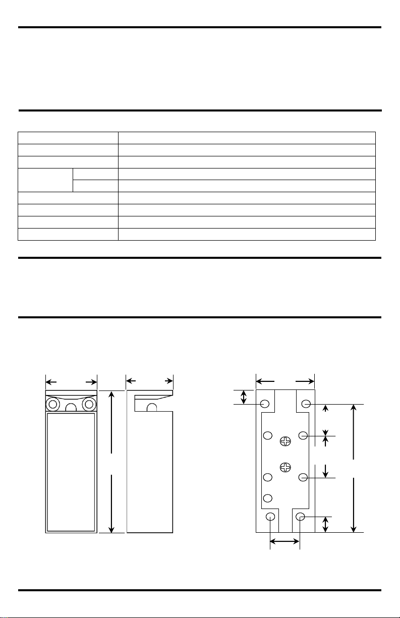
Dimensions
31/4"x13/16"x11/8" (82x30x28 mm)
Parts List:
1x Cabinet lock body
1x Lock plate
1x Manual
7x 1" Wood screws
1x Stainless steel cover
Front
Side
Mounting Holes
9
/16"
(15mm)
31/4"
11/8"
13/16"
15
/16"
(24mm)
29/16"
(65mm)
11
/16"
(18mm)
13
/16"
(21mm)
3
/8"
(9mm)
/16"
(8mm)
-in lock status sensor allow for monitoring whether
(30mm)
(82mm)
(28mm)
5
2 SECO-LARM U.S.A., Inc.
Page 3

SECO-LARM Electric Deadbolt Cabinet Lock
Fig.2
Fig.3
Fig.4
Fig.1
1. Remove the 2 holding screws from the back of the lock
2.
3. Reverse the solenoid direction (fig.2) to either match the
4.
5.
Selecting Fail-safe/Fail-secure Operation:
Fail-safe
Fail-secure
Installation:
1. Set the cabinet lock to either fail-safe or fail-secure by removing the solenoid and reversing its
2.
3.
4.
5.
Lock status
sensor
Lock body
Tape cover
body (fig.1).
Remove the lock body and the wires from the solenoid.
proper fail-safe (fig.3) or fail-secure position (fig.4).
Put the wires back through the access hole.
Replace the screws.
Position
direction if needed (see "Selecting Fail-safe/Fail-secure Operation" above).
Mount the cabinet lock body. For positioning of mounting holes, refer to "Overview" dimensions
and diagrams (page 2).
Determine the location of the lock plate, ensuring that the hole in the lock plate aligns with the
deadbolt. Install the lock plate with 2 included screws. Check alignment and adjust if necessary.
For wiring instructions, see "Wiring Connections and Diagram" (page 4).
Remove the tape cover and apply the stainless steel cover onto the adhesive tape (Ensure that
the cover is clean and free of oil or dirt before applying).
Position
Lock plate
SECO-LARM U.S.A., Inc. 3
Stainless
steel cover
Page 4

SECO-LARM Electric Deadbolt Cabinet Lock
Lock Status Sensor
Wiring Connections and Diagram:
Sample Applications:
Sliding door (case)
Swinging door (cabinet)
Drawer
12VDC
24VDC
Red
Black
+
Blue
White
-
Power
Black
Blue
Red
White
+
-
Power
Fail-safe wire
connection
Fail-secure
wire connection
Lock status
wire connection
NOTICE: The information and specifications printed in this manual are current at the time of publication. The
SECO
LARM reserves the right to
change specifications without notice.
Trademarks are the property of
SECO
Copyright © 2016
This material may not be reproduced or copied, in whole or
in part, without the written permission of SECO-LARM.
LIMITED WARRANTY:
LARM product is warranted against defects in material and workmanship while
used in normal service for
obligation is limited to
the repair or replacement of any defective part if the unit is returned, transportation prepaid, to SECO
This Warranty
is void if damage is caused by or attributed to acts of God, physical or electrical misuse or abuse, neglect, repair or
alteration, improper or abnormal usage, or faulty installation, or if for any other reason SECO-LARM determines that such
equipment is not operating properly as a result of causes other than defects in material and workmanship. The sole
oblig
LARM and the purchaser’s exclusive remedy, shall be limited to the replacement or repair only, at
SECO
LARM be liable for any special, collateral, incidental, or consequential
personal or property damage
SECO-LARM® U.S.A., Inc.
16842 Millikan Avenue, Irvine, CA 92606
Website: www.seco-larm.com
Phone: (949) 261-2999 | (800) 662-0800
Email: sales@seco-larm.com
Blue
White
Yellow
Fig.5
Fig.6
Fig.7
This SECO-
one (1) year from the date of sale to the original customer. SECO-LARM’s
ation of SECO
-LARM’s option. In no event shall SECO-
-LARM policy is one of continual development and improvement. For that reason, SECO-
-LARM USA Inc. or their respective owners.
4 SECO-LARM U.S.A., Inc.
-
of any kind to the purchaser or anyone else.
SECO-LARM is not responsible for misprints.
SECO-LARM U.S.A., Inc. All rights reserved.
-LARM.
MI_SD-997C-GCQ_160412.docx
PITVW2
 Loading...