

Page 1
Installation Manual
11/16” (37mm)
15
/
16
” (24
.5mm)
21/4” (57mm)
1
1
/2”
(37.5mm)
31/8” (80mm)
1
/8” (3mm)
51/2” (140mm)
Bolt
5
/
8
” (16mm) Throw
77/8” (200mm)
SD-997A-DQ - Fail-Secure
SD-997BQ - Fail-Safe
Electric Deadbolt
The SD-997A-DQ/BQ are designed for hollow metal
door frames. They are not recommended for wooden
door frames. However, the door can be wood or metal.
Features
•
Adds concealed deadbolt security to most wood or hollow
metal doors, with the convenience of electrical operation.
•
Stainless steel bolt, 5/8” diameter, 5/8” throw.
•
SD-997A-DQ --
•
SD-997BQ -- Fail-safe operation (unlocks if power is lost).
•
Door open/close monitor (NO/C/NC).
•
Adjustable door lock delay timer - see Specifications.
•
Magnetic switch senses door position for positive locking.
•
Attempts to lock multiple times if the door is not closed
properly, to prevent solenoid from burning out.
•
Use with an optional digital keypad for high security
without a key.
•
Easily connects to SECO-LARM’s SK-1011-SQ Electronic
Keypad.
•
Suitable for office-type applications.
•
Shallow design for use with most metal door jambs.
3
“
/
4
(19.3mm)
Fail-secure operation (locks if power is lost).
5
1
“
/
8
4
(105mm)
/8
SD-997A-DQ
3
“
(162mm)
/
6
8
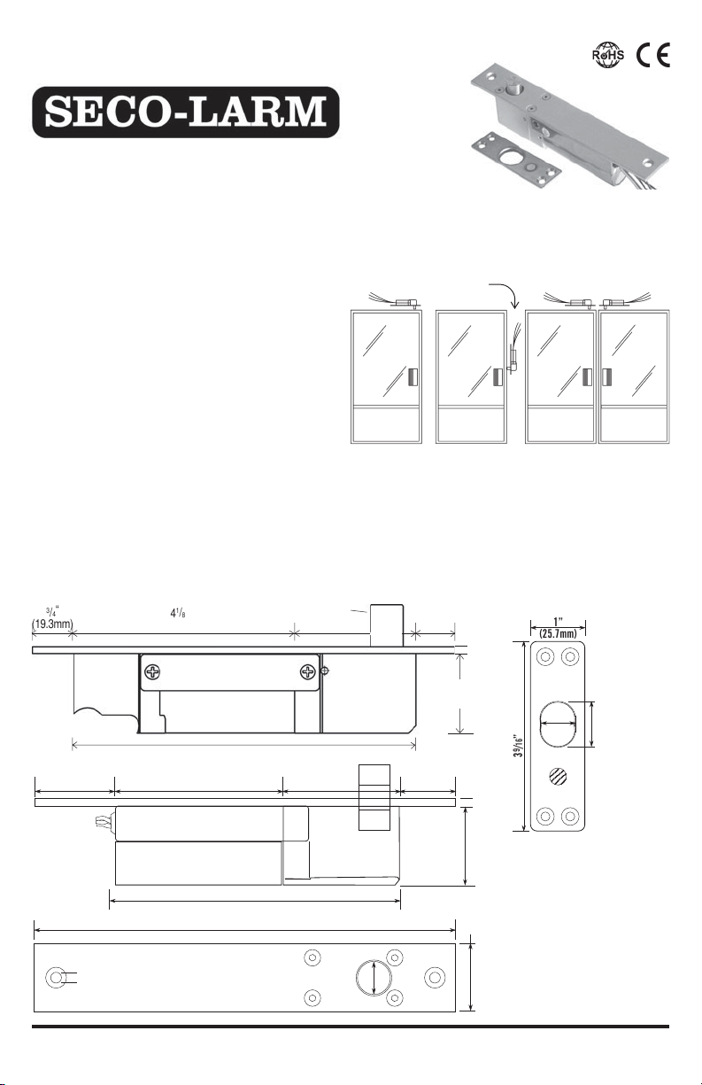
Fig. 1 - Possible Mounting Locations
Important - For vertical mounting of SD-997BQ only, wires
must come out the top of the unit.
For single door
•
•
Mounting Location
Can be mounted opposite the door hinges, or on the header
or on top of the door away from the hinges. Mounting on the
bottom of the door is not recommended because of the
possibility of dirt and dust buildup. (see fig. 1)
“
(16mm) Throw
1
“
(57.5mm)
/
4
2
SD-997BQ shown
For single door For double doors
Powered by a solenoid.
Stainless steel for strength and long life.
3
“
/
4
(19mm)
(37.5mm)
1
1
(3.5mm)
“
/
2
1
/
(25.7mm)
“
8
(18mm)
” (90mm)
16
/
9
3
1”
11
/16”
” (24.5mm)
16
/
15
SD-997BQ
Dimensions:*
(16m m)
Bolt
5/8”
(5.6mm)
1
/4”
Note: Products with model numbers that end with "Q" or that have a round green"Q"sticker are RoHS compliant.
(31.8mm)
1
1
/4”
Sensor Magnet
*Note: Original measurements
taken in millimeters. Inches are
closest 1/16” approximation.
Page 1
Page 2
Electric Deadbolt Installation Manual Electric Deadbolt Installation Manual
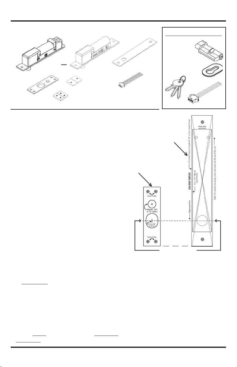
Fig. 2 - What’s Included:
Lock body x 1
SD-997A-DQ
Strike
Plate x 1
or
SD-997BQ
Mounting tabs
(large) x 2
Mounting tabs
(small) x 2
Installation
1. Determine where the deadbolt will be mounted (see fig. 1).
2. Tape the templates to the door frame and door (see fig. 3)
A. Align the templates so that the deadbolt of the lock body template
is centered on the deadbolt hole of the strike plate template.
B. Make sure to leave enough room at the ends of the lock body
and strike plate templates for mounting the mounting tabs.
3. Door frame cut (see fig. 4)
A. Cut out the space for the lock body.
B. Test the fit. The SD-977A-DQ/SD-997BQ lock body should
fit snugly inside the space.
C. Drill two 5mm screw holes as shown on the
4. Door cut and mount. (see fig. 4)
A. For wood doors:
1) Use a chisel to knock out a 3mm (1/8-inch) deep space as
shown on the template.
2) Drill the magnet hole, 12mm (1/2”) wide by 6mm (1/4”) deep.
3) Use four wood screws to mount the strike plate in the
chiseled space. The magnet should fit in the magnet hole.
4) Use a drill to drill out the deadbolt hole to a depth of 16mm (5/8”).
B. For hollow metal doors:
1) Cut out the space for the strike plate.
2) Drill two screw holes for each of the two mounting tabs.
3) Use screws to fix the mounting tabs inside the hollow metal door.
4) Use screws to fix the strike plate to the mounting tabs.
5. Door jamb cut and mount (see fig. 4)
A. Cut out the space for the face of the lock body.
B. Drill one 5mm hole for each of the two mounting tabs.
C. Use screws to fix the mounting tabs inside the door jamb.
D.
SD-997A-DQ only: Insert the lock/unlock cylinder (see fig. 5).
E. Connect the wires, and insulate them (see fig. 7):
1) Red – Power input (+)
2) Brown – Power input (-)
3) Orange – Control wire (ground to release bolt)
4) Green – Door monitor, COM
5) Yellow – Door monitor, N.C. (active when door closed)
{
*
6) Blue – Door monitor, N.O. (active when door open)
IMPORTANT – Correct polarity of the red and brown
wires is critical. If you reverse polarity, the solenoid
will burn out!
template.
SD-997A-DQ Also Includes:
Manual
lock/unlock
cylinder x 1
Faceplate x 1
Oval cylinder
plate x 2
6-Pin
connector x 1
• Templates x 4
• Mounting screws
Keys x 3
Fig. 3 - Aligning
Lock body template
Strike plate template
Line up these marks
IMPORTANT – Push all the wires into the door frame. If
space is a problem, cut away part of the dust catcher inside
the frame, or carefully chip away part of the drywall, being
careful not to damage the wall.
F. Set the door lock delay timer (see fig. 8). This is the
time it takes the deadbolt to automatically lock after
the door is closed.
NOTE: The deadbolt automatically relocks 4 seconds after
an optional external push button (egress button) is
pressed, if the door was not opened.
The lock body has a sensor mechanism wherein it can
detect if the strike plate is in close proximity (such as
when the door is closed). If the door was closed but
somehow the strike plate was not aligned properly, the
door monitor indicator may indicate that the door is
3-Pin
connector x 1
SECO-LARM U.S.A., Inc. SECO-LARM U.S.A., Inc.
Page 3
closed but the deadbolt remains unlock. During this time the
lock body may attempt multiple times to lock the door and if it
fails, it will stop to prevent the solenoid from burning out.
However if the lock body and the strike plate are too far
apart, the lock body will not attempt to lock the door and the
deadbolt will not throw out.
IMPORTANT – The lock body and strike plate must be
properly aligned and next to each other in order for the
product to function properly.
G.
Pull the vinyl covering off the faceplate, and place the faceplate
over the face of the lock body. Use screws to fix the faceplate
and lock body to the mounting tabs.
6. For SD-997A-DQ only (see figs. 5 and 6)
Because the SD-997A-DQ offers fail-secure operation, the door
locks if power to the unit is cut. For such a situation, a separate
manual lock/unlock cylinder is provided for manual operation.
A. Insert the cylinder as shown in Fig. 5, and secure it to the
lock body with the provided long screw. Turning the key or
the manual knob will unlock the SD-997A-DQ manually.
B. Two separate templates are included for drilling holes in the
door frame for the key and manual knob.
C. A separate 3-pin connector for the SD-997A-DQ can be
connected to an alarm panel or annunciator to alert when
the door is locked or unlocked.
SD-997A-DQ/SD-997BQ
body
Fig. 7 - Wiring
N.C.
N.O.
See fig. 8
Red wire
Green wire - door monitor, COM
Yellow wire - door monitor, N.C.
Blue wire - door monitor , N.O.
Purple wire - active if door is locked (N.C.)
Gray wire - manual lock/unlock (COM)
Black wire - active if door is unlocked (N.O.)
IMPORTANT – Do not cut wires before the plug as warranty
will be voided.
Fig. 8 - Setting Door Lock Delay Timer
SD-997A-DQ
SD-997BQ
Fig. 4 - Door and Frame Cuts
Max. 50mm
SD-997A-DQ
only*
*
See separate
template.
Door frame
Door
Fig. 5 - Manual Lock/Unlock Cylinder
(SD-997A-DQ only):
Note:
If cylinder is used,
max. depth of door
frame is 50mm.
cylinder to lock
Screw to secure
Fig. 6 - Installation of Manual Lock/Unlock Cylinder (SD-997A-DQ only):
Installation at side of door
Installation at top of door
COM
Brown wire
Card reader
or keypad
Orange
(active when door closed)
(active when door open)
Push
button
12VDC
only
1Amp
{
For
SD-997A-DQ
only
Drill hole
for lock
Drill hole
for lock
Drill hole for lock
Drill hole for lock
Page 3Page 2
Page 4
11/16” (37mm)
15
/
16
” (24
.5mm)
21/4” (57mm)
1
1
/2”
(37.5mm)
31/8” (80mm)
1
/8” (3mm)
51/2” (140mm)
Bolt
5
/
8
” (16mm) Throw
77/”(200
)
Electric Deadbolt Installation Manual
Installed by:_________
___
_______
Date:_________________________
Tel:___________________________
Web:_________________________
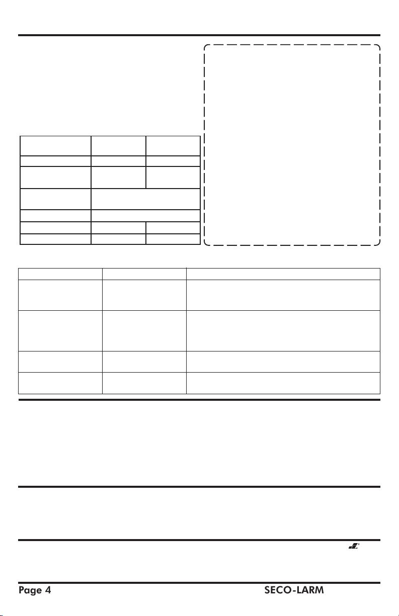
Specifications
Operation
Current Draw
Status Sensor
Operation Voltage
Adjustable Delay Timer
Weight (approx.)
SD-997A-DQ
Fail-Secure Fail-Safe
Standby: 320mA Standby:360mA
Activated: 880mA Activated: 900mA
SPDT, 500mA @ 12VDC
0, 3, 5, 9 secs. 0, 2.5, 5, 9 secs.
2lbs.,7oz. (1.1 kg.) 1lb.,13oz.(0.82kg.)
SD-997BQ
(N.O./C./N.C.)
12VDC
Troubleshooting:
Problem:
Deadbolt does not activate
when the door closes.
Deadbolt activates when
the door is closed, but
does not lock the door.
How to reset unit.
For any other problems
Possible cause:
The sensor in the lock body
is too far from the magnet
in the strike plate.
Deadbolt may not be
properly going into the
deadbolt hole in the door.
Installation notes:
Solutions:
• Try adjusting the strike plate, lock body position, or shims.
• Make sure the deadbolt is going into the hole and not hitting the
strike plate. If not, you must reposition the strike plate.
• If the deadbolt is going into the hole, it may be hitting the bottom of
the hole (if it is in a wooden door). In this case, drill a deeper hole.
• When testing, if necessary, reset the unit by grounding the orange
wire momentarily.
• Replace the unit, and test again. A problem unit can also be substituted
for a working unit in another door frame to see if it works there.
WARRANTY: This SECO-LARM product is warranted against defects in material and workmanship while used in normal service
for a period of one (1) year from the date of sale to the original consumer customer. SECO-LARM’s obligation is limited to the repair
or replacement of any defective part if the unit is returned, transportation prepaid, to SECO-LARM.
This Warranty is void if damage is caused by or attributed to acts of God, physical or electrical misuse or abuse, neglect, repair, or
alteration, improper or abnormal usage, or faulty installation, or if for any other reason SECO-LARM determines that such equipment
is not operating properly as a result of causes other than defects in material and workmanship.
The sole obligation of SECO-LARM, and the purchaser’s exclusive remedy, shall be limited to replacement or repair only, at SECO-LARM’s
option. In no event shall SECO-LARM be liable for any special, collateral, incidental, or consequential personal or property damages of any
kind to the purchaser or anyone else.
NOTICE: The information and specifications printed in this manual are current at the time of publication. However, the
SECO-LARM policy is one of continual development and improvement. For this reason, SECO-LARM reserves the right to change
specifications without notice. SECO-LARM is also not responsible for misprints or typographical errors.
Copyright © 2011 SECO-LARM U.S.A., Inc. All rights reserved. This material may not be reproduced or copied, in whole or in part,
without the written permission of SECO-LARM.
SECO-LARMSECO-LARM
SECO-LARM
SECO-LARMSECO-LARM
16842 Millikan Avenue, Irvine, CA 92606
U.S.A., Inc.U.S.A., Inc.
U.S.A., Inc.
U.S.A., Inc.U.S.A., Inc.
Tel: 800-662-0800 / 949-261-2999 Fax: 949-261-7326
Page 4
Website: www.seco-larm.com
E-mail: sales
@
MiSD997A-D_BQZZ_1106.pmd
seco-larm.com
SECO-LARM U.S.A., Inc.
PITSW2
 Loading...