

Page 1
• Static strength – 1,000 lbs. (454kg)
• 12/24 VDC Operation
Features:
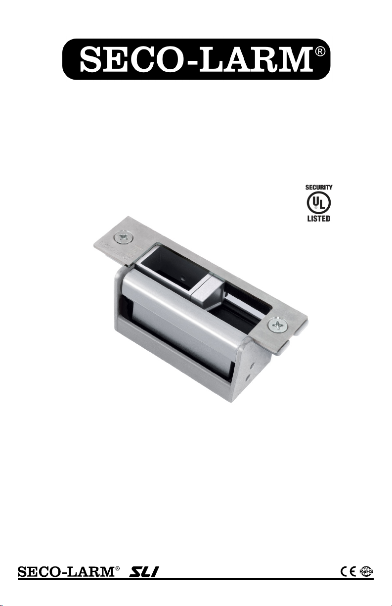
SD-996C-NUVQ
43RG
Electric Door Strike
with Vertical Adjustment
Manual
• Vertical adjustable deadbolt opening, sliding
shim keeper, and deadlatch ramp
accommodates a wide range of lock types
• Accommodates deadbolts up to 1"
• Field selectable for fail-safe or fail-secure
• Includes 5 different stainless-steel faceplates
• Includes trim plate to hide gaps in installation
• Reversible non-handed design fits either
right-hand or left-handed doors
• Indoor Use Only
• Tested to 250,000 cycles (UL Tested)
• Low current draw: 300mA@12VDC &
150mA@24VDC
• The SD-996C-NUVQ is intended to be used with
UL Listed Exit Hardware
• The SD-996C-NUVQ shall not impair the intended
operation of an emergency exit
• The SD-996C-NUVQ shall not impair the operation
of panic hardware mounted on the door
Page 2

SECO-LARM Electric Door Strike with Vertical Adjustment
Specifications:
Parts List:
Quick Installation:
1x
Door strike
5x
Faceplates
1x
Mounting template
2x
Electrical connectors
2x
Crimp connectors
2x
Mounting tabs
1x
Trim plate
2x
Trim plate screws
2x
Wood screws
6x
Machine screws
2x
Faceplate screws
2x
Self-tapping screws
The SECO-LARM SD-996C-NUVQ Electric Door Strike with Vertical Adjustment is compatible with
a wide range of lock types including cylindrical, mortise, and mortise exit devices and can be
configured for use in wood, aluminum, or metal doors. Included are various ANSI
that can be easily installed on the strike to match the door loc
field-configurable for fail-safe or fail-secure applications.
Model
SD-996C-NUVQ
Operating voltage
12/24 VDC
12VDC
300mA
24VDC
150mA
Operating temperature
14°~113° F (-10°~45° C)
Operating humidity
0~85%
Static strength
1,000 lbs. (454kg)
Dynamic strength
33 ft-lbs. (4.56 m-kgs)
Latch throw
1" (25mm) max with 1/8" (3mm) door gap
Dimensions
113/16"x15/8"x35/16" (47x42x84 mm)
Note: Not all parts will be used in every installation.
1. Select the type of faceplate that will be used. See “Sample Installations,” on page 5. If the door
7.
8.
Introduction:
k type and the strike is easily
Current draw
-sized faceplates
is pre-cut for a strike, skip to step 6.
2. Measure and mark the door latch line and the center line of the door. See “Measuring the
Latch Line & Center Lines,” page 3.
3. Apply the included stick-on template to the door frame. See “Mounting the Template,” page 3.
4. Prepare the door frame for installation and mount the trim plate if needed. See “Preparing the
Door Frame” and “Mounting the Trim Plate,” page 4.
5. If the door frame material is unsuitable for mounting the strike directly, use the included
mounting tabs for installation. This is recommended for aluminum door frames. See “Mounting
the Strike Using Mounting Tabs,” page 4.
6. Program for either fail-safe or fail-secure operation. See “Selecting Fail-Secure or Fail-Safe,”
page 6.
Connect power and complete installation to frame. See “Wiring Diagram,” page 6.
Adjust the keeper if needed to correct for any installation problems, page 7.
2 SECO-LARM U.S.A., Inc.
Page 3
SECO-LARM Electric Door Strike with Vertical Adjustment
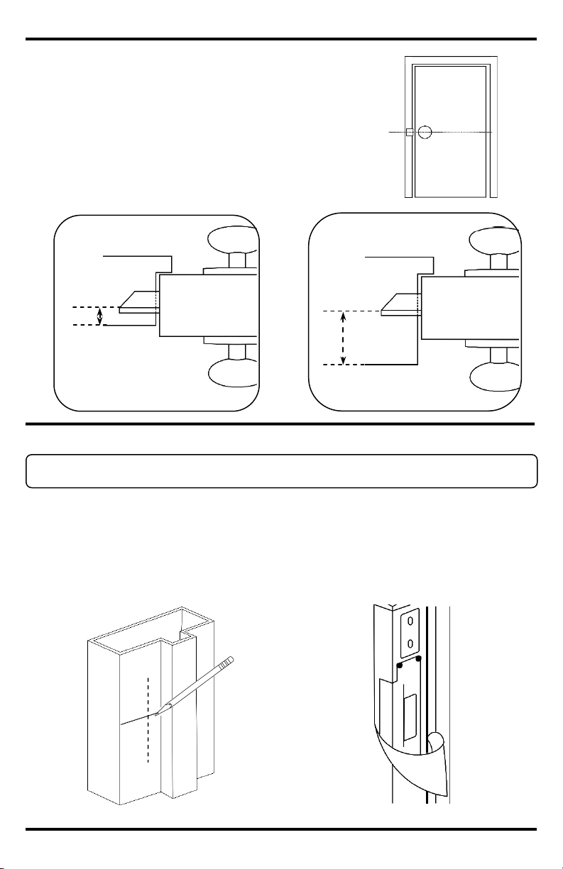
Mounting the Template:
Measuring the Latch Line & Center Lines:
1. Measure the center line of the door. This is shown
2.
Y
Door closed, sitting
Center
X
Door frame
Door
Door latch
line
1. Measure distance “X” from the side of the door frame, and distance “Y" from the top of the
2.
3.
X
Y
Note: The electric strike must be installed in such a way and in such a location as not to impair
the operation of any emergency exit and panic-mounted hardware on the door.
Door closed, sitting
Door frame
Door
X
Door latch
as “Y” on the diagram to the left.
Measure the distance from the door latch to the
edge of the door frame. This is the door latch line.
This is shown as “X” on the diagrams below.
line
outside door frame
inside door frame
line
door frame. Use a pencil to mark the exact spot where the two lines intersect.
Carefully peel off the short, thin tab in the center of the stick-on template. When placed
against the frame, this opening in the template will easily line up with the X-Y mark.
Peel the template from the backing, and carefully apply it to the door frame.
SECO-LARM U.S.A., Inc. 3
Page 4

SECO-LARM Electric Door Strike with Vertical Adjustment
Note: The mounting tabs are only used for
commonly done when retrofitting door frames.
To mount the strike where the hollow door frame
material is unsuitable for mounting,
the following:
1.
2.
Mounting the Trim Plate:
Mounting the Strike Using Mounting Tabs:
Mounting Tabs
Using the stick-on template as a guide:
installation.
Preparing the Door Frame:
Note: Trim plate is optional and may not be
plate to cover any gaps in the door frame.
1. If the hole cut for the faceplate is too large
2.
into the mounting holes
Machine
Screws
1. Drill holes for mounting the strike, and cut a
hole for the face-plate size being used. It is
recommended to cut the hole slightly
smaller than necessary.
2. Use a file to finish the shaping of the frame.
This will improve the fit and finish of the
or is jagged, the trim plate can be mounted
over the hole to improve the appearance of
the installation.
Screw the trim plate
at the top and bottom of the door strike
using the included trim plate screws before
installing the strike to the door frame.
required in all installations. Only use the trim
Punch or drill holes according to the template
for installation of the mounting tabs, and the
anchor nuts that reinforce them.
When installing, do not over-tighten the screws
as small adjustments may be required to
secure a snug fit for the door strike.
aluminum and metal door frames. This is
4 SECO-LARM U.S.A., Inc.
do
Page 5

SECO-LARM Electric Door Strike with Vertical Adjustment
Latchbolt Installation
For
the mounting tabs shown in "Mounting the Strike Using Mounting Tabs," page 4:
Sample Installations:
Dead
For installation of SD
shown in “Mounting the Strike Using Mounting Tabs,” page 4:
SD-996SS-11L1Q
Note: If it is necessary to cut a hole in the frame, mounting tabs
SD-996SS-11D1Q
SD-996SS-11D2Q
SD-996SS-11L3Q
SD-996SS-11L2Q
11/4"
47/8" (124mm)
21/4" (58mm)
11/18" (28mm)
11/2"
19/16" (40mm)
19/16" (40mm)
13/4"
11/4"
47/8" (124mm)
11/4"
11/16" (27mm)
11
/16" (18mm)
31/8" (80mm)
47/8" (124mm)
11/4"
11/8" (29mm)
7
/8" (22mm)
215/16" (74mm)
47/8" (124mm)
11
/16" (18mm)
213/16" (72mm)
11/4"
47/8" (124mm)
15/16"
(34mm)
-bolt Latch Installation
-996SS-11D1Q and SD-996SS-11D2Q faceplates with the mounting tabs
may be required to strengthen the installation. See pg. 4.
(32mm)
(32mm)
installation of SD-996SS-11L1Q, SD-996SS-11L2Q, and SD-996SS-11L3Q faceplates with
(38mm)
(32mm)
(44mm)
(32mm)
SECO-LARM U.S.A., Inc. 5
(32mm)
Page 6

SECO-LARM Electric Door Strike with Vertical Adjustment
1. Use the included electrical connector
For 24VDC Operation*:
For 12VDC Operation*:
12VDC
12V
24VDC
24V
Black Wire
Red Wire
White Wire
*
Diagrams are for illustrative purposes only. Polarity of wires is not important.
Crimp connectors are provided to make wiring
connections easier and more reliable. To install
the connectors:
12/24 VDC Wiring Diagram*:
FAIL-SECURE
FAIL-SAFE
SECO-LAR
M
®
FAIL-SECURE
FAIL-SAFE
SECO-LARM
®
Installing the Crimp Connectors:
Crimp
Connector
Factory default: Fail-safe
Selecting Fail-Secure or Fail-Safe:
1. Remove the locking screw and loosen the sliding screw.
2.
Fail Safe:
Fail Secure:
Locking
Sliding
screw
1. Insert the wires into the connector
(see "12/24 VDC Wiring Diagram," page 6).
2. Use a crimping tool or pliers to evenly press
down on the head of the connector.
marked 12VDC and connect its
red/black wires to the positive and
negative terminals of the control device.
marked 24VDC and connect its
white/black wires to the positive and
negative terminals of the control
device.
Slide the sliding screw to the desired setting. Replace the locking screw and retighten both
screws.
6 SECO-LARM U.S.A., Inc.
Page 7

SECO-LARM Electric Door Strike with Vertical Adjustment
Keeper
Shim
Cylindrical Lock
Deadlatch
Strike Adjustment:
1. Extend the deadbolt while moving the
2.
3.
Adjusting Deadbolt Keeper:
1. Move the door close to the strike and
2.
Adjusting Deadlatch Ramp:
To minimize door play, slide the keeper
shim up and down to align
bolt position.
Adjusting Keeper Sliding Shim:
For cylindrical lock applications, remove the
keeper sliding shim from the strike to ensure
proper latch throw depth.
Adapting for Cylindrical Locks:
door closer to the strike, allowing the
two to touch.
Mark deadbolt limit lines on the strike
keeper.
Open the door and adjust the deadbolt
keeper up and down to align with the
marked lines.
mark the deadlatch limit lines on the
strike keeper when they meet.
Open the door and adjust the deadlatch
ramp up and down to align with the
marked lines.
Deadbolt
Keeper
Up
and
Down
Up
and
Down
Ramp
with the latch
Latch
Bolt
Up
and
Down
Sliding
SECO-LARM U.S.A., Inc. 7
Keeper Sliding Shim
Page 8

SECO-LARM Electric Door Strike with Vertical Adjustment
Door Strikes
Door Holders
Magnetic Locks
Exit Devices
SD-995C / SD-994C shown
DH-151SQ shown
E-941SA-1200 shown
SD-962AR-36A shown
Troubleshooting:
Also Available from SECO-LARM®:
• Unmount the strike and check that the electrical connector is
working properly.
• Check that the door latch is operating properly, and replace if
moving it or adding washers or shims.
Strike makes a buzzing sound
• Connect the strike to a DC power supply.
NOTICE: The SECO-LARM policy is one of continual development and improvement. For that reason, SECO-LARM
reserves the right to change specifications without notice. SECO-LARM is not responsible for misprints. Trademarks are the
property of SECO
Copyright © 2016 SECO
.A., Inc. All rights reserved. This material may not be reproduced or copied, in whole or
in part, without the written permission of SECO
LIMITED WARRANTY: This SECO-LARM product is warranted against defects in material and workmanship while used in
normal service
LARM’s obligation is limited to the
repair or replacement of any defective part if the unit is returned, transportation prepaid,
This Warranty is
void if damage is caused by or attributed to acts of God, physical or electrical misuse or abuse, neglect, repair or alteration,
improper or abnormal usage, or faulty installation, or if for any other reason SECO
ines that such equipment is
not operating properly as a result of causes other than defects in material and workmanship. The sole obligation of
SECO
’s
option.
LARM be liable for any special, collateral, incidental, or consequential personal or property
damage of any kind to the purchaser or anyone else.
SECO-LARM® U.S.A., Inc.
16842 Millikan Avenue, Irvine, CA 92606
Website: www.seco-larm.com
Phone: (949) 261-2999 | (800) 662-0800
Email: sales@seco-larm.com
Fail-safe or fail-secure
available
Surface-mount or
flush-mount available
• Ensure the electrical connector is connected to a 12 or 24VDC
Electric strike does not activate
• Use a multimeter to test that the strike is receiving the proper
• Make sure the activation device (keypad or push-button switch) is
Door does not open when the
electric strike is activated
• The position of the electric strike may need to be adjusted by
80, 300, 600, and 1200-lb
holding force available
Fits doors 30"~48"
Stainless-steel,
connected properly.
source.
voltage and amperage. If it is not, it may be necessary to use
heavier gauge wires, or increase the output of the power supply.
necessary.
for three (3) years from the date of sale to the original customer. SECO-
-
LARM and the purchaser’s exclusive remedy, shall be limited to the replacement or repair only, at SECO-LARM
In no event shall SECO-
-LARM U.S.A., Inc. or their respective owners.
8 SECO-LARM U.S.A., Inc.
-LARM U.S
-LARM.
to SECO-LARM.
-LARM determ
MI_SD-996C-NUVQ_160930.docx
PITGW1
 Loading...