

Page 1

ELECTRONIC CONTROL UNIT LRX
2205
Single-phase electronic control unit with incorporated radio
receiver for the automation of sliding and swinging gates and
rolling shutters, at power levels of up to 1500 Watts.
- Mod. LG 2205 : Without radio receiver
- Mod. ( LR 2205 ) : 306 Mhz
- Mod. ( LR 2205 / 330 ) : 330 Mhz
- Mod. ( LR 2205 / 418 ) : 418 Mhz
- Mod. LRS 2205 : 433.92 Mhz
- Mod. LRS 2205 SET : 433.92 Mhz “narrow band”
- Mod. LRH 2205 : 868.3 Mhz “narrow band”
( ) Product intended for those countries where its use is
permitted
TECHNICAL DATA:
- Power supply : 230 V a/c 50-60 Hz 2100 W max.
- Flashing beacon output : 230 V a/c 500 W max.
- Motor output : 230 V a/c 1500 W max.
- Photoelectric cells
power supply : 24 V a/c 3 W max.
- Low voltage safety
features and commands : 24 V c/c
- Operating temperature : -10 ÷55 °C
- Radio receiver : see model
- Op. transmitters : 12-18 Bit or Rolling Code
- Max stored TX codes : 75
- Box dimensions : 110 x 121 x 47 mm.
- Container : ABS V-0 (IP54).
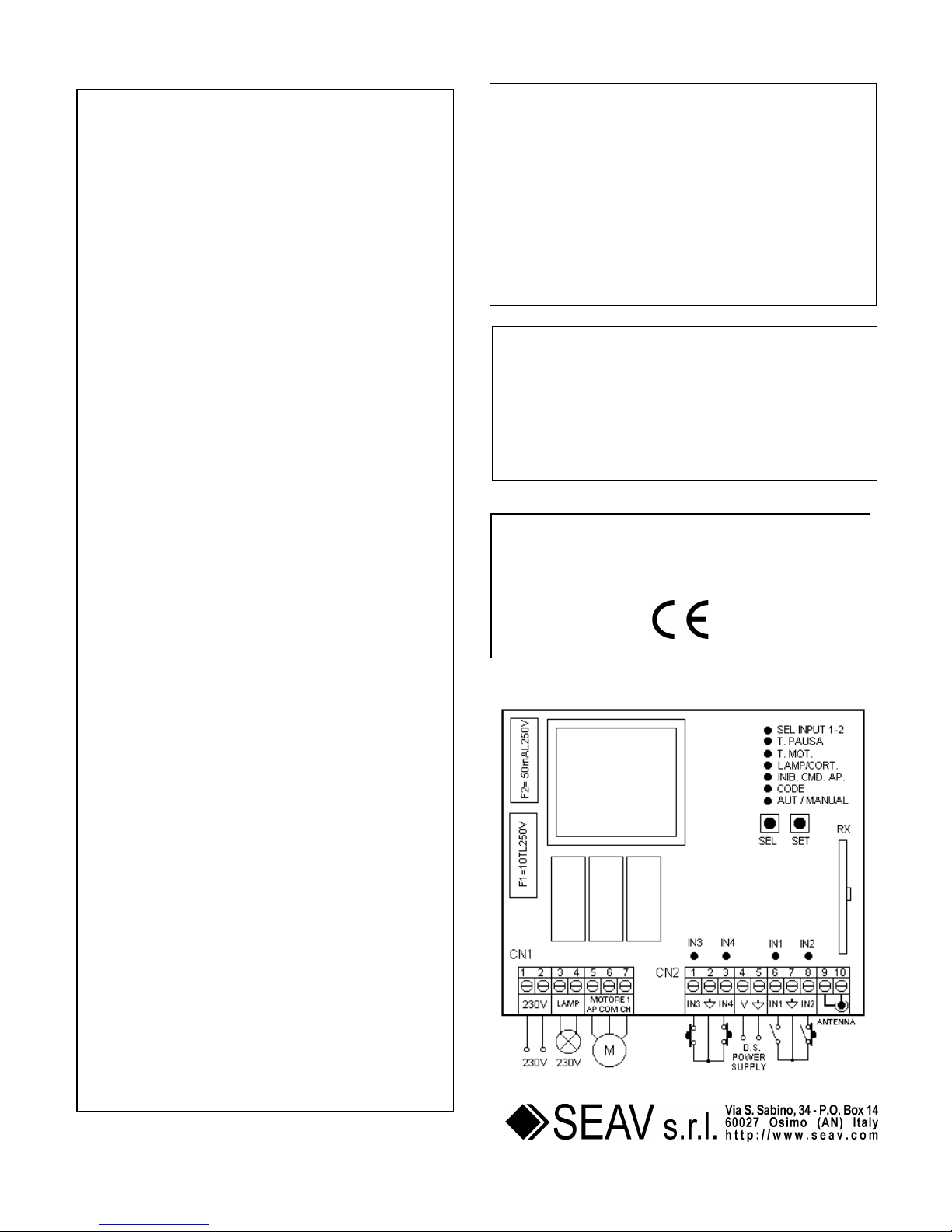
TERMINAL BOARD CONNECTIONS:
CN1:
1 : 230 V a/c line input (Phase).
2 : 230 V a/c line input (Neutral).
3 : Clean contact output for Flashing Beacon/Courtesy Light.
4 : Clean contact output for Flashing Beacon/Courtesy Light.
5 : Opening motor output.
6 : Shared motor output.
7 : Closing motor output.
CN2:
1 : Input IN3 = FCAP opening stop limit (NC).
: Input IN3 = DS2 safety device inverts during closure,
2 : Shared GND input.
3 : Input IN4 = FCCH closing stop limit (NC).
: Input IN4 = DS3 safety device inverts during closure,
Stop during opening (NC).
4 : Photoelectric cell control and power supply (24 V a/c).
5 : Photoelectric cell control and power supply (GND).
6 : Input IN1 = P/P open-close command button (NA).
Input IN1 = UP open only command button (NA).
7 : Shared GND input.
8 : Input IN2 = DS1 safety device inverts during closure (NC).
Input IN2 = DOWN close only command button (NA).
Input IN2 = BL device. Emergency lock (NC).
9 : Earth antenna input.
10 : Antenna hot pole input.
OPERATIONAL DATA:
Step-by-Step keypad operation:
The following operation is obtained using the low voltage
keypad to control the shutter:
the first press opens the gate until the motor timer reaches zero
or until the opening stop limit is reached, the second press
closes the gate; if a button is pressed before the opening stop
limit is reached, the control unit stops motion during both
opening and closing. A further command restarts motion in the
opposite direction.
Operation using different models of radio control:
Different models of radio control may be programmed: by
storing a code (1 button) a cyclic step by step operation (Open
- Stop - Close) may be achieved, and by storing two different
codes (2 buttons) separate commands are created, one for
opening and one for closing. Storing three different codes (3
“BeFree” series buttons) produces three separate commands:
the first for Open, the second for Stop and the third for Close.
Operation using a 1-button radio control:
The following type of operation is obtained using a radio control
with a single button: the first press controls the opening
movement of the shutter until the motor timer stops. The
second press controls the closing movement of the shutter. If
the button is pressed before the motor stops running, the
control unit will stop the shutter from moving and the button will
need to be pressed again to reactivate the motor in the
opposite direction.
Operation using a 2-button radio control:
The following type of operation is obtained using a radio control
with 2 buttons: the first button (“Up”, corresponding to the
opening movement) controls opening until the motor stops
running and the second button (“Down”, corresponding to the
closing movement) controls the closure of the shutter. If the
opening movement is interrupted with another “Up” command,
the motor will continue to run in the upward movement
direction. If, however, the movement is interrupted with a
“Down” command, the control unit will stop the motor.
The procedure is the same for the closing movement phase.
Operation using a 3-button radio control (BeFree series):
The following type of operation is obtained using a radio control
from the BeFree series: the Up button controls the opening
movement until the set motor time has elapsed, the Stop button
makes the shutter stop and the Down button controls the
closure of the shutter. If a stop command is sent during the
opening or closing movement, the control unit causes this
movement to stop. If a command which is the opposite
direction to the current movement is sent during the opening or
closing movement, the control unit causes the shutter to
change direction.
Automatic closing:
The control unit can close the shutter automatically without
sending additional commands.
The selection of this operation mode is described in the Pause
Time programming mode.
DS1 safety device operation:
DS1 operation anticipates the connection of a general safety
device with contact (NC). If not used, this input must be
bridged.
Action is not taken into account during the opening stage but
causes inverted motor action during the closing stage. Another
safety device operating mode is described in the
extended menu when programming DS1 = INV or DS1 =
Lock.
Rev. 1.1 04 -10 - 2007
1
GB
Page 2
DS2 safety device operation:
DS2 operation anticipates the connection of a general safety
device with contact (NC). If not used, this input must be
bridged.
Action is not taken into account during the opening stage but
causes inverted motor action during the closing stage.
DS3 safety device operation:
DS3 operation anticipates the connection of a general safety
device with contact (NC). If not used, this input must be
bridged.
An intervention during the opening or closing stage causes the
movement to stop.
Operation with TIMER:
The control unit may be connected to a timer instead of using
the open-close command button ( IN1 ).
Example: at 8:00 a.m. the timer closes the contact and the
control unit opens the shutter; at 6:00 p.m. the timer opens the
contact and the control unit closes the shutter. Between 8:00
a.m. and 6:00 p.m. at the end of the opening phase, the control
unit disables the flashing beacon, the automatic closing stage
and the radio controls.
PROGRAMMING:
SEL button: selects the type of function to be stored; selection
is indicated by a flashing LED.
The desired function can be selected by pressing the button
repeatedly. The selection remains active for 10 seconds
(indicated by the flashing LED); after 10 seconds, the control
unit returns to its original status.
SET button: programmes the information according to the type
of function selected previously using the SEL button.
IMPORTANT: The function of the SET button can be replaced
with the radio control, if programmed previously (CODE LED
on).
MAIN MENU
The control unit is supplied by the manufacturer with the option
of selecting some important functions.
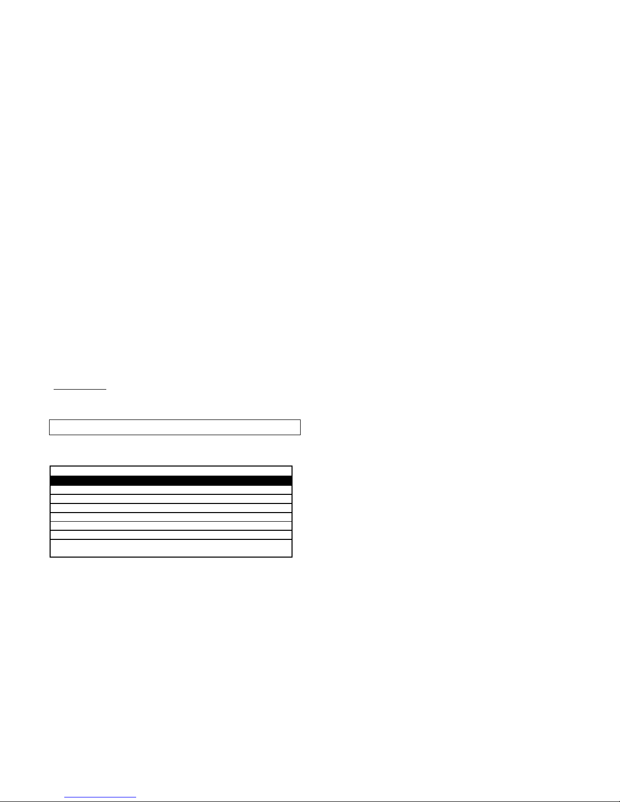
---------------------- MAIN MENU -----------------
Reference LED LED Off LED On
1) AUT/MANUAL Step-by-Step User Present
2) CODE No code Code entered
3) INB.CMD.AP Disabled Enabled
4) LAMP/CORT Flashing Courtesy light
5) T. MOT. Automatic motor time Time programmed
6) T. PAUSA. Without aut. closing With aut. closing
7) SEL INPUT 1 - 2 IN1 = P/P - IN2 = DS1 IN1 = Up - IN2 =
Down
1) AUT/MANUAL (Step-by-Step /Manual operation):
The control unit is supplied by the manufacturer with the
manual “User Present” operation mode disabled. To
enable the function proceed as follows: use the SEL button to
navigate to the AUT/MANUAL LED when flashing and press
the SET button: the AUT/MANUAL LED will then remain lit in a
fixed manner and programming is complete.
In this mode, using both the radio control and the low voltage
keypad to control the gate, the following operation is obtained:
the control is constantly enabled so that the gate or shutter can
be moved as necessary. The movement stops immediately
when the control is released. Repeat the operation to restore
the previous configuration.
2) CODE: (Radio control code)
The control unit can store up to 75 radio controls with different
fixed or rolling codes.
Programming using a 1- or 2-button radio control:
To programme the transmission codes in the radio control,
proceed as follows: press the SEL button and the CODE LED
will begin to flash; at the same time send the first code ("Up",
corresponding to the opening movement) on the radio control.
At this point the CODE LED will begin to flash quickly. Send the
second code (“Down”, corresponding to the closing movement)
to be stored and the CODE LED will remain lit: programming is
now complete. If the second code is not sent within 10 seconds
the control unit exits the programming stage, selecting
operation using one button on the radio control.
Programming using a 3 button radio control in the “BeFree
Series”:
The control unit allows you to store the whole “BeFree” radiocontrol by programming only the UP button.
To programme the “BeFree” radio-control codes, follow this
procedure: press the SEL button; the CODE LED begins to
flash. Press the UP button of the desired radio control at the
same time; the CODE LED will remain lit and programming will
be complete.
Deleting the codes: To delete all transmission codes
stored in the memory, proceed as follows: press the SEL
button; the CODE LED starts flashing. Then press the SET
button; the CODE LED switches off and the procedure is
complete.
Radio control already stored warning:
The control unit can store up to 75 radio controls with different
fixed or rolling codes. If the user attempts to perform the
programming procedure for a radio control which is already
stored in the memory, the CODE LED will begin to flash rapidly
for a few moments to indicate that this procedure cannot be
performed; the unit then returns to the programming stage once
again.
Maximum number of radio controls which can be stored :
The control unit can store up to 75 radio controls with different
fixed or rolling codes. If the maximum number of radio controls
has been reached, and a programming process started, the
control unit will indicate that the programming process has
failed by flashing all the LEDs except the CODE LED, which
will remain lit in a constant manner. After 10 seconds the
control unit exits the programming mode.
3) INB. CMD. AP: (command inhibition during opening and
pause time, if entered)
The command inhibition function during opening and pause
time, if entered, is used when automation includes the loop
detector. During opening or pause time the control unit ignores
the commands given by the loop detector, keypad and radio
control. During the closing phase a command sent by the loop
detector, keypad or 1-button radio control will cause the motor
direction to be inverted; if operating with a 2-button radio
control the button corresponding to opening movement will
cause the motor direction to invert and the closing movement
button is ignored; if operating with a radio control in the BeFree
series the opening movement button causes inversion, the
closing movement button is ignored and the Stop button
causes the motor to stop.
The control unit is supplied with the default setting of the
command inhibition function during opening and pause time not
enabled. To enable the function proceed as follows: use the
SEL button to reach the stage when the INB.CMD.AP LED is
flashing, then press the SET button: at this moment the
INB.CMD.AP LED lights up and remains constant. Repeat the
operation to restore the previous configuration.
4) LAMP/CORT: (Selection of flashing beacon or courtesy
light)
The control unit has an output of 230 V a/c 500 W for
connection to a flashing beacon or courtesy light.
The control unit is supplied by the manufacturer with the
flashing beacon function enabled (even when the unit is
paused). To enable the flashing beacon function, proceed as
Rev. 1.1 04 -10 - 2007
2
Page 3
follows: use the SEL button to navigate to LAMP/CORT when
the corresponding LED is flashing, then press the SET button:
the LAMP/CORT. LED lights up and remains constant.
Repeat the operation to restore the default configuration.
To enable the courtesy light, repeat the operation above, by
pressing the SEL button twice (LAMP/CORT LED flashes
rapidly) instead of once. Repeat the operation to restore the
default configuration.
Flashing beacon function while the unit is paused:
The 230 V a/c output will activate every time automation takes
place, for the duration of the motor timer. If the Pause Time is
stored, the 230 V a/c output will also be active during the
Pause.
Flashing Beacon operation: The 230 V a/c output will
activate every time automation takes place, for the duration of
the motor timer.
Courtesy Light operation: The 230 V a/c output will activate
for 3 minutes every time an opening command is given.
5) T. MOT: (Programmed motor operation time: max. 4 minutes)
The control unit is supplied by the manufacturer with the
Automatic Motor Timer enabled, this way the control unit
removes the power supply from the motor 1 second after it has
reached the internal stop limit of the motor. If there is an
established motor operation time and an Automatic Motor
Timer which is disabled, proceed as follows when the shutter is
closed to perform the programming process: use the SEL
button to reach the stage where the T. MOT LED flashes, then
press the SET button briefly; the Motor will begin the Opening
cycle. When the shutter reaches the desired position press the
SET button. The motor time is stored and the T. MOT. LED
remains lit in a constant manner.
To restore the initial configuration (with the Automatic Motor
Timer function enabled) navigate to the stage where the T.
MOT. LED is flashing then press the SET button twice within 2
seconds; the LED switches off and the operation is complete.
During programming the radio control button on the control unit
can be used instead of the SET button, if stored previously.
6) T. PAUSA: (Programmed aut. closing time: max. 4 min.)
The control unit is supplied by the manufacturer without an
automatic closing procedure. To enable the automatic closing
function, proceed as follows: use the SEL button to reach the
stage where the T. PAUSA LED is flashing, then press the SET
button, wait for the desired pause time, then press the SET
button again for a moment; the automatic closing time is stored
and the T. PAUSA LED remains lit in a constant manner.
To restore the initial configuration (without automatic closing)
navigate to T.PAUSA when the corresponding LED is flashing
then press the SET button twice within 2 seconds; the LED
switches off and the operation is complete.
During programming the radio control button on the control unit
can be used instead of the SET button, if stored previously.
7) SEL IN1 - 2: (Selection of IN1 – IN2 operation)
The control unit is supplied by the manufacturer with the
following IN1 and IN2 input selection: input IN1 is used for the
connection of a cyclical “P/P” command button (NA) and input
IN2 for the connection of a general safety device DS1 with
contact (NC).
If you wish to select a different operating mode for inputs IN1
and IN2, proceed as follows: use the SEL button to reach a
stage where the SEL INPUT 1-2 LED is flashing and press the
SET button: the SEL INPUT 1-2 LED lights up in a constant
manner and programming is complete. The IN1 input thus
becomes the button connection (NA) solely for the “UP”
opening phase and IN2 becomes the button connection (NA)
solely for the ”DOWN” closing phase. Repeat the operation to
restore the previous configuration.
EXTENDED MENU
The control unit is supplied by the manufacturer with the option
of selecting only the functions listed in the main menu.
To enable the functions of the extended menu proceed as
follows: press and hold the SET button for 5 seconds; the
T.PAUSA and SEL INPUT LEDs will flash alternately and the
user has 30 seconds within which to select the functions of the
extended menu using the SEL and SET buttons. After another
30 seconds the control unit returns to the main menu.
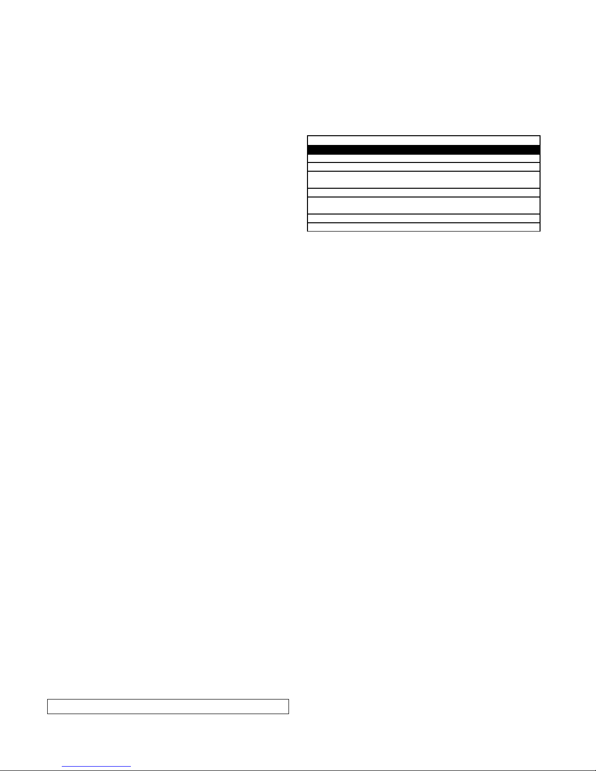
---------------------- EXTENDED MENU -----------------
Reference LED LED Off LED On
A) AUT/MANUAL Step-by-Step Inverting
B) CODE remote PGM = OFF remote PGM = ON
C) INB.CMD.AP. Test DS1 – DS2 = OF Test DS1 – DS2 =
ON
D) LAMP/CORT DS1 = INV in closure DS1 = Lock
E) T.MOT IN3 = FCAP - IN4 = FCCH IN3 = DS2 - IN4 =
DS3
F) T. PAUSA Flashing beacon ON/OFF
G) SEL INPUT 1 - 2 Flashing beacon ON/OFF
A) AUT/MANUAL (Step-by-Step /Inverting operation):
The control unit is supplied by the manufacturer with the
Inverting operation mode disabled. To enable the function
proceed as follows: check that the extended menu is enabled
(T.PAUSA and SEL INPUT 1-2 LEDs start flashing alternately),
use the SEL button to navigate to the AUT/MANUAL LED when
it is flashing and press the SET button: the AUT/MANUAL LED
lights up and programming is completed.
In this mode, using both the radio control and the low voltage
keypad to control the gate, the following operation is obtained:
the first press opens the gate until the end of the motor time,
the second press closes it; if a button is pressed before the end
of the motor running time, the control unit inverts motion both
during opening and closing. Repeat the operation to restore the
previous configuration.
B) CODE
(Remote programming of radio control):
The control unit allows the transmission code to be
programmed by remote, without using the SEL button.
To programme the transmission code remotely, proceed as
follows: send a code, continuously and for a period of longer
than 10 seconds, from a radio control stored previously: the
control unit enters its programming mode as described
previously for the CODE LED in the main menu.
The control unit is supplied by the manufacturer with remote
programming of the transmission code not enabled; to enable
the function proceed as follows: check that the extended menu
is enabled (the T.PAUSA and SEL INPUT 1-2 LEDs flash
alternately), using the SEL button navigate to CODE LED when
flashing and press the SET button: the CODE LED lights up
and programming is completed. Repeat the operation to restore
the previous configuration.
C) INB. CMD. AP
(Photoelectric cells DS1 and DS2 operation test):
The control unit is supplied by the manufacturer with the
photoelectric cells test disabled; if you wish to enable the
function (in compliance with EN 12453), proceed as follows:
check that the extended menu is enabled (T.PAUSA and SEL
INPUT 1-2 LEDs flash alternately), using the SEL button
navigate to INB.CMD.AP LED when flashing and press the SET
button: the INB.CMD.AP LED lights up and programming is
completed. This is how the photoelectric cells test for the safety
inputs (inversion during closure) defined as DS1 and DS2 is
performed. Repeat the operation to restore the previous
configuration.
D) LAMP/CORT (Selecting DS1 operation):
The control unit is supplied by the manufacturer with DS1 = INV
in the closure phase, or rather with the operating mode for
Rev. 1.1 04 -10 - 2007
3
Page 4

normal photoelectric cells connection enabled (intervention
causes the inversion of the motor during closure).
If you wish to define DS1 = Lock, or rather with the operating
mode for the normal connection of an emergency command
enabled (intervention causes the motor to stop immediately in
both directions), proceed as follows: check that the extended
menu is enabled (T.PAUSA and SEL INPUT 1-2 LEDs start
flashing alternately), use the SEL button to navigate to the
LAMP/CORT LED when it is flashing and press the SET button:
the LAMP/CORT LED lights up and programming is completed.
Repeat the operation to restore the previous configuration.
E) T. MOT (Selecting Input IN3 – IN4 operation):
The control unit is supplied by the manufacturer with inputs IN3
and IN4 = FCAP and FCCH for the normal connection of
opening and closing stop limits.
If you wish to define inputs IN3 and IN4 = DS2 and DS3, or
rather with the operating mode for the normal connection of
photoelectric cells (or other types of safety devices) enabled,
proceed as follows: check that the extended menu is enabled
(the T.PAUSA and SEL INPUT 1-2 LEDs flash alternately),
using the SEL button navigate to T.MOT LED when flashing
and press the SET button: the T.MOT LED lights up and
programming is completed. Repeat the operation to restore the
previous configuration.
RESET:
To restore the default configuration, press the SEL and SET
buttons simultaneously, all RED LEDs will light up and then
switch off.
ERROR INDICATION:
- The control unit enables errors or malfunctions to be identified
using Software tests. If there are errors or malfunctions on the
Input/Output devices, the control unit will indicate the status by
alternately activating and deactivating (for 5 seconds at a time,
and for a maximum period of 1 minute) the 230 V a/c 500 W
output for the connection of the flashing beacon or the courtesy
light.
This guarantees the monitoring of breakdowns in compliance
with Category 2 of EN 954-1. Whenever one of these
malfunctions occurs a qualified professional should be
contacted in order to fix it.
Test Driver Motor:
The control unit is fitted with two drivers used to control the
motor. If there is a malfunction, the control unit will not enable
motion of the shutter and will indicate the test failure visually
through the simultaneous flashing of all LEDs except the T.
MOT LED; which will remain lit in a constant manner. We
recommend that a qualified technician is contacted immediately
in order to resolve the problem. Once the correct operating
conditions are restored the control unit may be switched on
again. The error status is reset and the control unit is ready to
operate normally.
DS1 - DS2 safety device test:
The control unit is designed for connection to safety devices
(see Notes for the Installer section) which comply with point
5.1.1.6 of regulation EN 12453. If there is no connection and/or
a malfunction occurs, the control unit does not enable shutter
movement and provides a visual indication of the test failure
through the simultaneous flashing of all LEDs except the INB
CMD PA LED if the cause is the DS1 operating mode, or the
LAMP/CORT LED if the cause is the DS2 operating mode.
After the malfunction has been identified, the control unit
makes it possible to monitor only the opening movements when
a user is present, either using the keypad or the radio control
(when operating via a 2-button radio control the button
corresponding to the closing movement is disabled and when
operating via a 3-button radio control the closing movement
and Stop buttons are disabled). We recommend that a qualified
technician is contacted immediately in order to resolve the
problem. Once the correct operating conditions are restored the
control unit may be switched on again. The error status is reset
and the control unit is ready to operate normally.
HARDWARE DIAGNOSTICS:
INPUT IN1 - IN2 - IN3 - IN4 test:
The control unit is fitted with a red LED for every IN 1-2-3-4 low
voltage input so that the status may be monitored immediately.
Operating principle: LED on = input closed, LED off = input
open.
Rev. 1.1 04 -10 - 2007
4
Page 5
FOR THE USER - IMPORTANT
- The device should not be used by children or by individuals
with reduced physical or psychological abilities unless
supervision is provided or instruction given on how to operate
it.
- Do not let children play with the device; keep radio controls
out of their reach.
- CAUTION: Keep this instruction manual in a safe place and
adhere to the important safety instructions contained within it.
Non-adherence to these instructions may lead to property
damage and serious accidents.
- Examine the system frequently to check for any signs of
damage. Do not use the device if it needs to be repaired.
Warning
All operations which require the casing to be opened (such as
wire connection, programming, etc.) must be carried out during
installation, by skilled staff only. For any other procedure which
requires the casing to be opened again (re-programming,
repairs or site modifications), please contact the technical
assistance service.
Rev. 1.1 04 -10 - 2007
NOTES FOR THE INSTALLER
The control unit was designed for installation with other
components (motor, shutter or gate, safety devices) in order
to form a finished product (machine) in compliance with the
Machines Directive.
The safety of the final installation site and adherence to all
current legislation is the responsibility of the individual
assembling the various parts to construct a complete closure
device.
We advise that you also take note of the following
recommendations:
− Before shutter automation, it is necessary to check the
product is in good condition and that it complies with EN
12604 and the Machines Directive.
− The wiring of external electrical components must comply
with EN 60204-1 as amended in section 5.2.7 of EN
12453. Power supply leads and connection cables must
be secured through the use of cable clamps, which are
supplied with the product.
− The motor reducer used to move the shutter must comply
with section 5.2.7. of EN 12453.
− If present, the keypad for manual control must be
mounted in such a way that the user is not placed in a
dangerous situation, in compliance with point 5.2.8 of EN
12453.
− The control unit is not equipped with a 230 V a/c electric
line sectioning device. The installer is responsible for
installing a sectioning device in the system. An
omnipolar switch with overheating category III must be
installed. The sectioning device must be positioned so
that it is protected against accidental closure, in
compliance with section 5.2.9 of standard EN 12453.
− In compliance with EN 12453 it is recommended that
motor reducers fitted with an electromechanical
unlocking device are used, so that the door can be
moved manually if necessary.
− In compliance with point 5.4.3 of EN 12453,
electromechanical unlocking systems or similar devices
should be used as these enable the door to stop safely
at its stop limit.
− Power supply and motor connection cables which are
suitable for use in conjunction with the pg9 cable clamps
provided must have an external diameter with a
measurement between 4.5 and 7 mm. The internal
conductor wires must have a nominal cross-section of
0.75 mm². If a channel is not used, we recommend that
cables in H05RR-F material are used.
− The D.S. Power Supply outlet must be dedicated to the
powering of devices connected to DS1 and DS2
(photoelectric cells for example); other applications are
not permitted. A test may be performed using the control
unit at the beginning of every manoeuvring cycle to
make sure operation is taking place correctly. If several
of the abovementioned devices are used, they must be
connected in series.
We recommend the use of a safety device with NC
output, which is capable of monitoring its own correct
operation and which conforms to regulation EN 12978.
− Once installation is complete, all the checks listed in EN
12453 – EN 12445 must be performed so as to ensure
that closure occurs in compliance with all stipulations.
− For the radio receiver to operate correctly when two or
more control units are used, we recommend that you
install the devices at least 3 metres away from each
other.
SEAV s.r.l. hereby declares that the below products:
Electronic Control Unit:
LG 2205 - LRS 2205 - LRS 2205 SET - LRH 2205
conform to the specifications in the Directives
R&TTE 99/5/EC, EMC 2004/108/EC, LVD 2006/95.
5
 Loading...