

Page 1

ELECTRONIC CONTROL UNIT LRX 2186
Single-phase electronic control unit for the automation of sliding
or swinging gates with incorporated radio receiver.
- Mod. LG 2186 : Without radio receiver
- Mod. ( LR 2186 ) : 306 Mhz
- Mod. ( LR 2186 / 330 ) : 330 Mhz
- Mod. ( LR 2186 / 418 ) : 418 Mhz
- Mod. LRS 2186 : 433.92 Mhz
- Mod. LRS 2186 SET : 433.92 Mhz narrow band
- Mod. LRH 2186 : 868.3 Mhz narrow band
( ) Product intended for those countries where its use is
permitted
TECHNICAL DATA:
- Power supply : 230 Vac 50-60Hz 1100W max.
- Flashing beacon output : 230 Vac 500 W max.
- Motor output : 230 Vac 500 W max.
- Electric lock output : 12 Vdc 15 W max.
- Photoelectric cells power supply : 24 Vac 3 W max.
- Stop limit and low voltage commands : 24 Vcc
- Operating temperature : -10 ÷70 °C
- Radio receiver : see model
- Op. transmitters : 12-18 Bit or Rolling Code
- Max TX stored codes : 150 (CODE or CODE PED)
- Box dimensions : 190x140x70 mm.
- Container: : IP56.
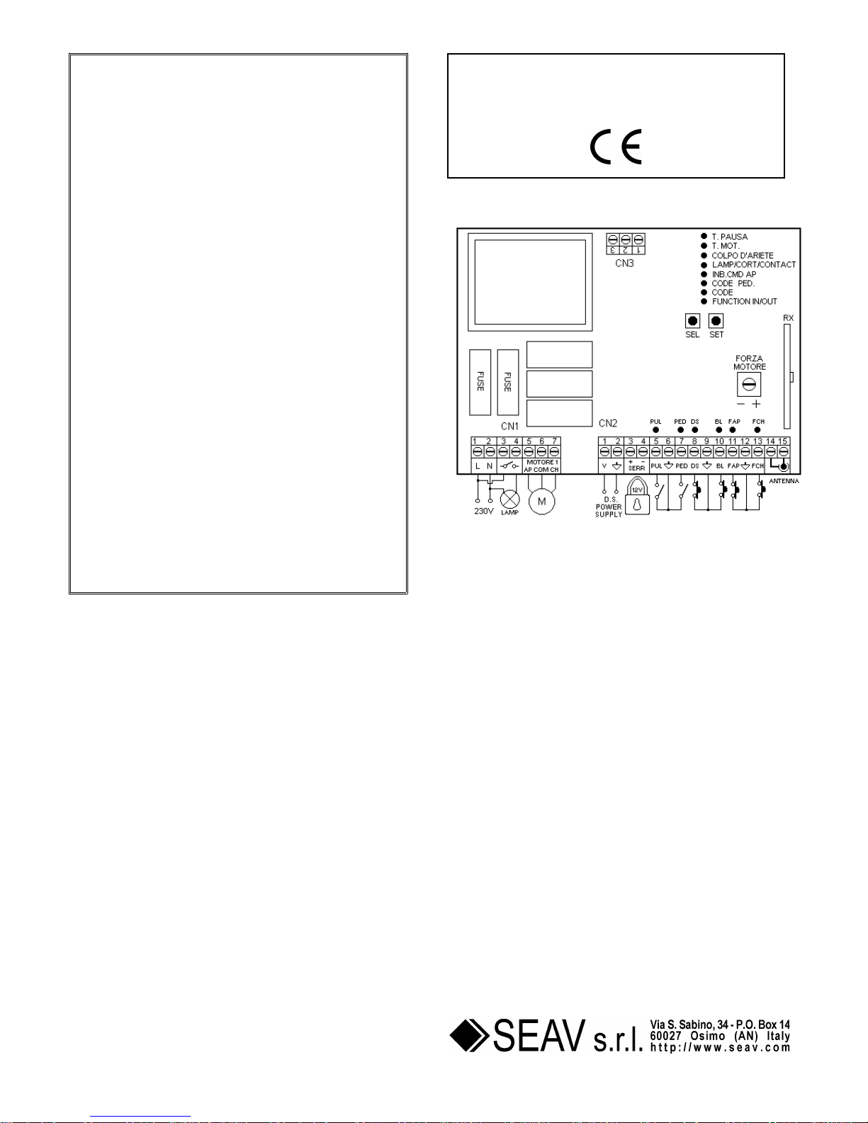
TERMINAL BOARD CONNECTIONS:
CN1:
1 : 230 Vac line input (Phase).
2 : 230 Vac line input (Neutral).
3 : Clean contact output for Flashing Beacon/Courtesy Light.
4 : Clean contact output for Flashing Beacon/Courtesy Light.
5 : Opening motor output.
6 : Common motor output.
7 : Closing motor output.
CN2:
1 : Photoelectric cells control and power supply (24 Vac).
2 : Photoelectric cells control and power supply (GND).
3 : 12 Vdc 15 W (+12V) electric lock output.
4 : 12 Vdc 15 W (GNC) electric lock output.
5 : PUL open-close command button input (NA).
6 : GND common input.
7 : PUL PED pedestrian command button input (NA).
8 : DS safety device input (NC).
9 : GND common input.
10 : BL block device input (NC).
11 : FCAP opening stop limit input (NC).
12 : GND common input.
13 : FCCH closing stop limit input (NC).
14 : Antenna earth input.
15 : Antenna hot pole input.
CN3:
1 : Output 1 for connection of Traffic Light Module ML 2192.
2 : Output 2 for connection of Traffic Light Module ML 2192.
3 : Output 3 for connection of Traffic Light Module ML 2192.
FUNCTIONAL DATA:
Step-by-Step Operation:
Using both the radio control (CODE LED on) and the low
voltage push-button station (PUL) to control the shutter, the
following operation is obtained:
the first impulse opens the shutter until the end of the motor
time or until the opening stop limit is reached, the second
impulse closes the shutter; if an impulse arrives before the
opening stop limit is reached, the control unit stops motion
both during opening and closing. An additional command
restarts motion in the opposite direction.
Automatic closing:
The control unit can close the shutter automatically without
sending additional commands.
The selection of this operation mode is described in the Pause
Time programming mode.
Pedestrian Passage :
Using both the pedestrian radio control (CODE PED. LED on)
and the low voltage push-button station (PED) to control the
shutter, the following operation is obtained: the first impulse
controls opening for 10 seconds, then the control unit makes a
10-second pause and closes the shutter.
Safety device:
The control unit allows for powering and connecting
photoelectric cells according to EN 12453.
The action is not considered during opening and causes
inverted motion during closing.
The control unit must use photoelectric cells connected to
dedicated inputs; otherwise the control unit is not enabled for
operation.
Lock input:
The control unit provides for connection of a lock button (NC).
The action in any operation stage stops motion immediately. An
additional motion command will be valid as long as the lock
input is deactivated, and in any case it will close the gate with
5-second pre-flashing.
If not used, this input must be bridged.
Initial pick-up and Motor Power Adjustment:
The electronic control unit is equipped with initial pick-up and
motor power adjustment functions that are fully managed by
the microprocessor.
The initial pick-up function is used to help the motor during
initial motion by powering the motor with maximum power for 2
seconds also when the motor power adjustment function is
enabled.
The motor power adjustment function is used to ensure correct
motion and at the same time block the shutter in case of
obstacles without causing harm to individuals or properties.
Deceleration:
The motor deceleration function is used to avoid high-speed
closing of swinging gates at the end of opening and closing.
Deceleration can be programmed at the desired points (before
total opening and closing) during Motor Time programming.
Traffic Light Management:
The control unit can manage two “Green/Red” traffic lights for
traffic control before and during the gate automation (by means
of connection to CN3 terminal board of optional accessory ML
2192). If selected, (FUNCTION IN/OUT LED on) you can have
two opening commands of the gate according to direction (i.e. if
you enter or exit). The two commands are obtained by
modifying the operation of the inputs (PUL – PUL PED) and
(CODE – CODE PED) that become operation commands for
the entrance and exit direction.
Operation with TIMER:
The control unit allows for connecting a timer instead of the
open-close command button (PUL).
Example: 8:00 a.m. the timer closes the contact and the control
unit commands opening, 6:00 p.m. the timer opens the contact
and the control unit commands closing. From 8:00 a.m. to 6:00
I
Page 2
p.m. at the end of opening the control unit disables the flashing
beacon, the automatic closing and the radio controls.
PROGRAMMING :
SEL key: it selects the type of function to store, selection is
indicated by flashing LED.
By pressing the key repeatedly, you can select the desired
function. The selection remains active for 10 seconds (flashing
LED); after 10 seconds, the control unit returns to the original
status.
SET key : it programmes the information according to the type
of function selected with the SEL key.
IMPORTANT: The function of the SET key can be replaced
with the radio control, if programmed previously (CODE LED
on).
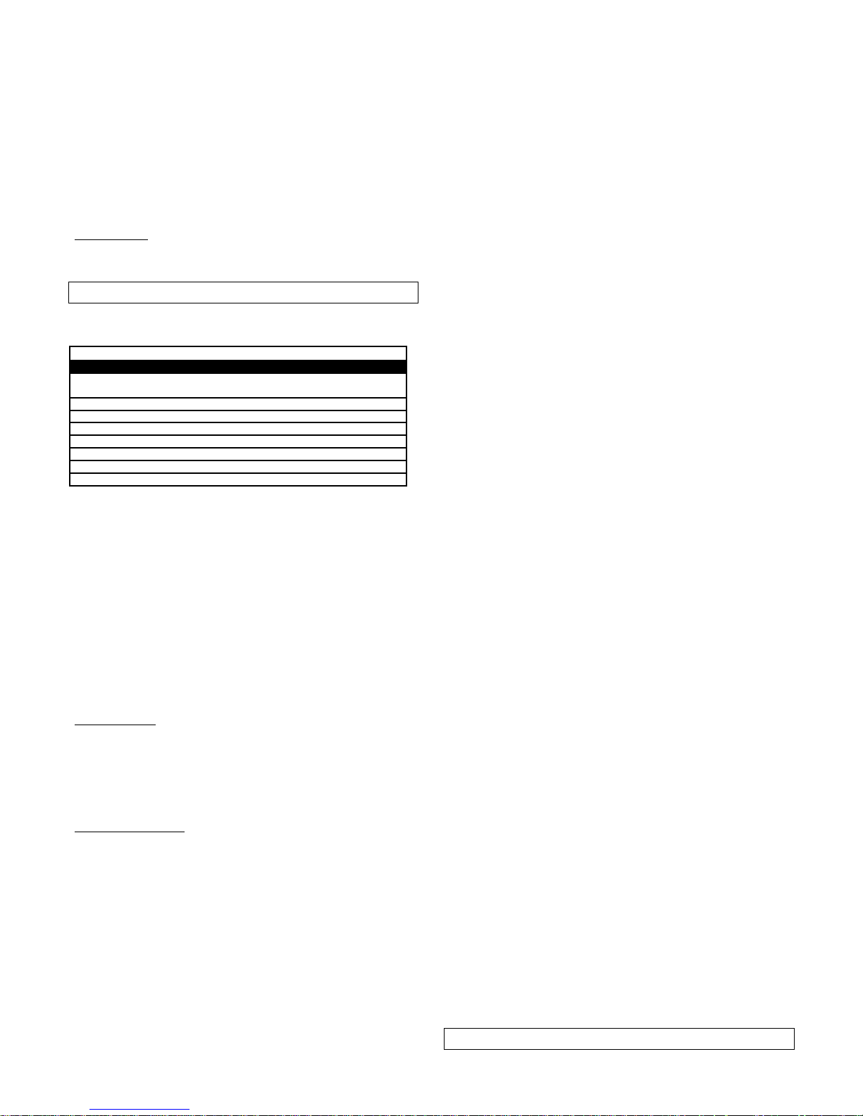
MAIN MENU
The control unit is supplied by the manufacturer with the
possibility of selecting some important functions.
---------------------- MAIN MENU -----------------
LED status LED off LED on
1) FUN. IN/OUT PUL/PED commands 2 x PUL IN/OUT
commands
2) CODE No code Code entered
3) CODE PED. No code Code entered
4) INB.CMD.AP Not enabled Enabled
5) LAMP/CORT/CO Flashing beacon Courtesy Light- Aux Contact
6) THE ARIES EFFECT Not enabled Enabled
7) T. MOT. 30 sec. motor time Programmed time
8) T. PAUSA. Without aut. closing With aut. closing
1) IN/OUT FUNCTION:
The control unit is supplied by the manufacturer with the PUL
and PEL PED command buttons enabled for standard
operation (FUNCTION IN/OUT LED off). If you need to enable
an operation mode that can manage a traffic light for traffic
control before and after motion (FUNCTION IN/OUT LED on),
follow this procedure: with the SEL key go to FUNCTION
IN/OUT LED when flashing, then press the SET key: the
FUNCTION IN/OUT LED turns on. Both 5-sec pause time and
command inhibition during opening are enabled. Repeat the
operation to restore the default configuration.
2) CODE : (Radio control code)
The control unit allows for storing 150 radio control with
different code of fixed or rolling type.
Programming.
To programme the transmission code follow this procedure:
with the SEL key go to CODE LED when flashing, send the
desired code with the radio control; programming is completed
when the CODE LEC remains on permanently. If you have
stored 150 codes and you repeat the programming operation,
all programming LED’s start flashing to indicate that no codes
can be stored.
Deleting the codes.
To delete all transmission codes stored in the memory, do as
follows: press the SEL key, the CODE LED starts flashing, then
press the SET key, the LED CODE turns off and the procedure
is completed.
3) CODE PED:(Pedestrian radio control code).
The programming and deleting procedure is the same as the
one illustrated above, with reference to the CODE PEDONALE
LED.
4) INB. CMD. AP: (command inhibition during opening and
pause time, if entered)
The command inhibition function during opening and pause
time, if entered, is used when automation includes the loop
detector. During opening or pause the control unit ignores the
commands given by the loop detector at every passage.
The control unit is supplied by default with the command
inhibition function during opening and pause time not enabled.
To enable the function follow this procedure: with the SEL key
go to INB.CMD.AP LED when flashing, then press the SET key:
the INB.CMD.AP LED turns on. Repeat the operation to restore
the previous configuration.
5) LAMP/CORT/CO: (Selection of flashing beacon, courtesy
light or auxiliary contact)
The control unit is provided with a clean relay contact output to
connect a flashing beacon, courtesy light or auxiliary contact
(i.e. for garage light command).
The control unit is supplied by the manufacturer with the
flashing beacon function enabled. To enable the courtesy light
follow this procedure: with the SEL key go to LAMP/CORT/CO
when flashing, then press the SET key: the LAMP/CORT/CO
LED turns on. To enable the auxiliary contact, repeat the
operation above, by pressing the SEL key twice
(LAMP/CORT/CO LED flashes rapidly) instead of once.
Flashing Beacon Operation: The clean relay contact
output will activate every time automation moves for the motor
time. If the Pause Time is stored, the relay contact will be
active also during the Pause.
Courtesy Light Operation: The clean relay contact output will
activate for 3 minutes every time an opening command is
given.
Auxiliary Contact Operation: The clean relay contact output
will activate for 1 second every time an opening command is
given.
6) THE ARIES (RAMMING) EFFECT :
The aries (ramming) effect function is used in gates with
electric locks to unlock the lock and permit the correct
execution of the opening operation. Before starting opening,
the control unit will send a closing command for 2 seconds.
The control unit is supplied by the manufacturer with the aries
(ramming) effect function not enabled. To enable the function
follow this procedure: with the SEL key go to C. ARIETE LED
when flashing, then press the SET key: the C. ARIETE turns
on. Repeat the operation to restore the previous configuration.
7) MOTOR TIME and DECELERATION: (Programming motor
operation time of max. 4 minutes)
The control unit is supplied by the manufacturer with predefined
motor operation time of 30 seconds without deceleration.
To modify the motor operation time, follow this procedure with
the shutter closed: with the SEL key go to T. MOT. LED when
flashing, then press the SET key rapidly, the Motor starts the
opening cycle; when the initial point of deceleration is reached
press the SET key again, the motor decelerates until the
desired position is reached, press the SET key to complete the
opening cycle. The T. MOT. LED starts flashing rapidly, now
repeat the programming operation of motor time and
deceleration for the closing cycle. To deactivate the
deceleration function, during programming, once the opening
and closing cycle is completed, press the SET key twice in a
sequence.
During programming the radio control key of the control unit
can be used instead of the SET key, if stored previously.
8) T. PAUSA: (Programming of aut. closing time of max. 4 min.)
The control unit is supplied by the manufacturer without
automatic closing. To enable automatic closing follow this
procedure: with the SEL key go to T. PAUSA when flashing,
then press the SET key, wait for the desired pause time, then
press the SET key again for a second; the automatic closing
time is stored and the T. PAUSA LED is on.
To restore the initial configuration (without automatic closing)
go to the T.PAUSA LED when flashing, then press the SET key
twice within 2 seconds; the LED goes off and the operation is
completed.
During programming the radio control key of the control unit
can be used instead of the SET key, if stored previously.
EXTENDED MENU
Page 3
The control unit is supplied by the manufacturer with the
possibility of selecting only the functions of the main menu.
To enable the functions of the extended menu follow this
procedure: press the SET key continuously for 5 seconds, the
T. MOT. and T. PAUSA LED’s flash alternatively and the user
has 30 seconds time to select the functions of the extended
menu with the SEL and SET keys, after 30 seconds the control
unit returns to the main menu.
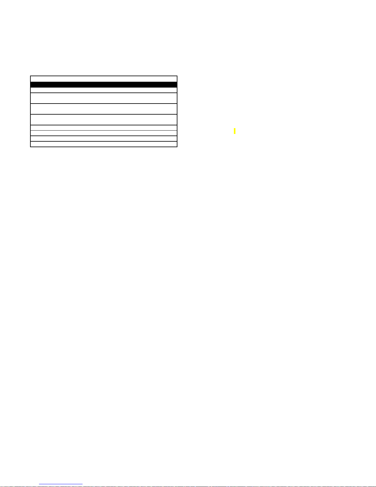
---------------------- EXTENDED MENU -----------------
LED status LED off LED on
A) FUN. IN/OUT remote PGM = OFF remote PGM = ON
B) CODE Photoelectric cells test = ON Photoelectric cells test =
OFF
C) CODE PED. Pressure Maint. = OFF Pressure
Maint. = ON
D) INB.CMD.AP Electronic brake = OFF Electronic
brake = ON
E) LAMP/CORT/CO Closure strike = OFF Colpo chiusura = ON
F) THE ARIES EFFECT Not used
G) T. MOT. Flashing beacon ON/OFF
H) T. PAUSA. Flashing beacon ON/OFF
A) FUNCTION IN/OUT
(Remote programming of radio control) :
The control unit allows for programming the transmission code
from remote, without using the SEL key.
To programme the transmission code from remote follow this
procedure: send the radio control code continuously for more
than 10 seconds, the control unit enters the programming mode
as illustrated above for the CODE LED in the main menu.
The control unit is supplied by the manufacturer with the
remote programming of the transmission code not enabled; to
enable the function follow this procedure: check that the
extended menu is enabled (T. MOT. and T. PAUSA LED’s start
flashing alternatively), with the SEL key go to FUNCTION
IN/OUT LED when flashing and press the SET key: the
FUNCTION IN/OUT turns on and programming is completed.
Repeat the operation to restore the previous configuration.
B) CODE (Photoelectric Cells Test):
The control unit is supplied by the manufacturer with the
photoelectric cells test is enabled (in compliance with EN
12453); to disable the function follow this procedure: check that
the extended menu is enabled (T. MOT. and T. PAUSA LED’s
start flashing alternatively), with the “SEL” key go to CODE LED
when flashing and press the “SET” key: the CODE turns on and
programming is completed. In this way the photoelectric cells
test is not performed; also if they are not connected (if not
used, DS2 input must be bridged) the control unit is enabled for
operation. Repeat the operation to restore the previous
configuration.
C) CODE PED: (Maintenance of Hydraulic Motor Pressure):
The control unit is supplied by the manufacturer with the
maintenance of hydraulic motor pressure not enabled. To
enable the function follow this procedure: check that the
extended menu is enabled (T. MOT. and T. PAUSA LED’s start
flashing alternatively), with the SEL key go to CODE PED LED
when flashing and press the SET key: the CODE PED LED
turns on and programming is completed. In this way the control
unit will send a closing command to the motor every 2 hours for
2 seconds. Repeat the operation to restore the previous
configuration.
D) INB. CMD. AP (Electronic Brake):
The control unit is supplied by the manufacturer with the
electronic brake function not enabled. To enable the function
follow this procedure: check that the extended menu is enabled
(T. MOT. and T. PAUSA LED’s start flashing alternatively), with
the SEL key go to INB. CMD. AP. LED when flashing and press
the SET key: the INB. CMD. AP. turns on and programming is
completed. The control unit reduces the forward motion of the
gate due to inertia in the presence of a stop or inversion
command. Repeat the operation to restore the previous
configuration.
E) LAMP/CORT/CO (Closure Strike) :
The control unit is supplied with the closure strike function not
enabled. To enable the function follow this procedure: check
that the extended menu is enabled (T. MOT. and T. PAUSA
LED’s start flashing alternatively), with the SEL key go to
LAMP/CORT/CO LED when flashing and press the SET key:
the LAMP/CORT/CO LED turns on and programming is
completed. If programmed with deceleration during closing, the
control unit will add a 1-second time at maximum power (after
completing the decelerated closing operation) to overcome the
lock, if any. Repeat the operation to restore the previous
configuration.
RESET :
To reset the default configuration, press the SEL and SET keys
simultaneously, all RED LED’s will turn on and then off.
DIAGNOSTICS:
Photoelectric Cells Test:
The control unit is set for the connection of safety devices
compliant with 5.1.1.6 section of EN 12453. The operation test
of connected photoelectric cells is performed at each
manoeuvring cycle. In case of no connection and/or no
operation, the control unit will not enable movement and will
visually indicate the test failure with simultaneous flashing of all
LED’s. Once the correct operation of the photoelectric cells has
been restored, the control unit is ready for operation. This
guarantees monitoring against failures in compliance with
Category 2 of EN 954-1.
Command input test:
The control unit is provided with a LED for each low voltage
command input to monitor the status immediately.
Operation principle: LED on = input closed, LED off = input
open.
Page 4
FOR THE INSTALLER - IMPORTANT
− Before gate automation, it is necessary to check the
good condition of the gate and its compliance with EN
12604 with respect to directive on machines.
− The control unit is not equipped with 230 Vac electric
line sectioning device. The installer is responsible for
installing a sectioning device in the system. The
sectioning device must be protected against accidental
closing in compliance with 5.2.9 section of EN 12453.
− Wiring of external electrical components must comply
with EN 60204-1 as amended in section 5.2.7 of EN
12453. The fixing of power supply leads and connection
cables must be secured through the use of cable
clamps supplied on demand.
− If present, the push-button station for manual control
must be mounted in such a way that the user is not in a
dangerous position.
− The motor reducer used to move the gate must comply
with section 5.2.7. of EN 12453.
− The D.S. Power Supply output must be dedicated to
photoelectric cell power supply. It must not be used for
other applications.
− The control unit tests the operation of photoelectric cells
at every manoeuvring cycle to guarantee protection
against failures of anti-compression devices of
Category 2 in compliance with section 5.1.1.6 of EN
12453. Therefore, it safety devices are not connected
and/or operated, the control unit is not enabled for
operation.
− The safety function guaranteed by the control unit is only
active during closing; therefore protection during
opening must be guaranteed during installation with
measurements (shelters or safety distances) that are
independent from the control circuit.
− For the correct operation of the radio receiver, if two or
more control units are used, we recommend you to
install the devices at least 3 metres away from each
other.
SEAV s.r.l. hereby declares that the products below:
Electronic Control Unit:
LG 2186 - LRS 2186 - LRS 2186 SET - LRH 2186
complies with requirements of Directives R&TTE 99/5/EC,
EMC 2004/108/EC, LVD 2006/95/EC.
Rel. 1.1 of 12-03-07
 Loading...