

Page 1
ELECTRONIC PANEL LRX 2145
Mono-phase electronic exchange, for the automation of swingdoors with incorporated receiver.
- Mod. LG 2145 : Without radio Receiver
- Mod. ( LRQ 2145 ) : 30,875 Mhz
- Mod. ( LR 2145 ) : 306 Mhz
- Mod. ( LRS 2145 / 330 ) : 330 Mhz
- Mod. ( LRS 2145 / 418 ) : 418 Mhz
- Mod. LRS 2145 : 433,92 Mhz “narrow band”
( ) This product is designed only for countries in which this
use is allowed
TECHNICAL DATA:
- Power supply : 230 Vac 50-60Hz 20W max.
- Flashing light output : 230 Vac 500 W max.
- Motor output : 230 Vac 500 W max.
- Electric lock output: 12 Vac 12 W max.
- Aux. power output : 24 Vac 5 W max.
- Warning light output: 24 Vac 4 W max.
- Limit switch and BT controls: 24 Vcc
- Working temperature: -20 ÷ 85 °C
- Radio receiver: refer to type
- Op. transmitters: 12-18 Bit or Rolling Code
- TX max. codes in memory : 120 (CODE or CODE PED)
- Container dimensiond: 240x185x110 mm.
- Protection capability: IP 65
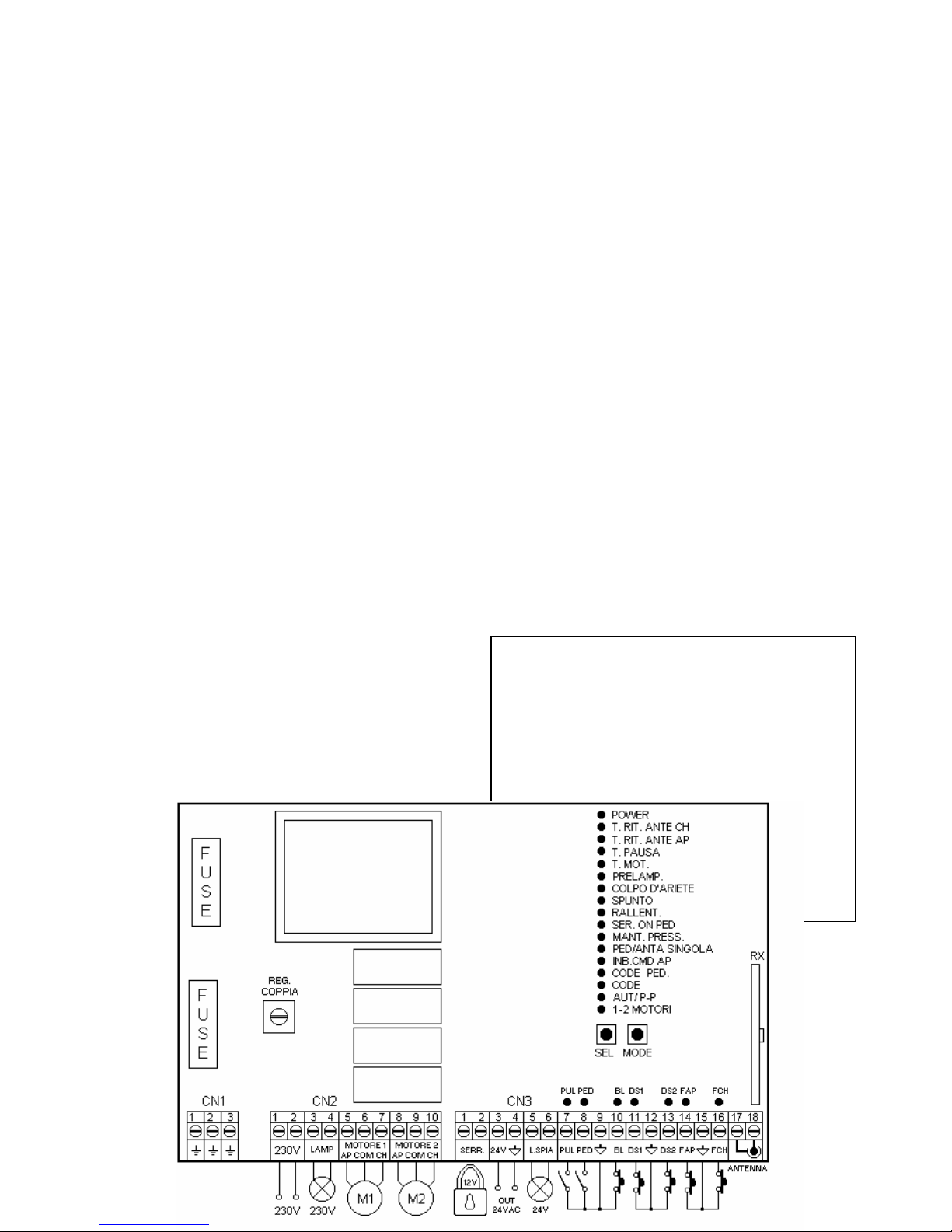
TERMINAL BOARD CONNECTION:
CN1 : Terminal board
1 : Earth.
2 : Earth.
3 : Earth.
CN2 : Terminal board
1 : 230 Vac input.
2 : 230 Vac input.
3 : 230 Vac flash input .
4 : 230 Vac flash input .
5 : Opening 1 motor output.
6 : Common 1 motor output.
7 : Closing 1 motor output.
8 : Opening 2 motor output.
9 : Common 2 motor output.
10 : Closing 2 motor output.
CN3 : Terminal board
1 : Electric lock feed output 12 Vac 12 W.
2 : Electric lock feed output 12 Vac 12 W.
3 : 24 Vac 5 W service feed output .
4 : 24 Vac 5 W service feed output .
5 : Warning light output 24 Vac 4 W.
6 : Warning light output 24 Vac 4 W.
7 : Open-close push button input (NA).
8 : Single pedestrian push button input (NA).
9 : Common GND input .
10 : Input lockout (NC).
11 : Safety device input 1 (NC).
12 : Common GND input .
13 : Safety device input 2 (NC).
14 : Opening limit switch input (NC).
15 : Common GND input .
16 : Closing limit switch input (NC).
17 : Aerial earth input .
18 : Aerial hot pole input.
IMPORTANT NOTICE FOR THE INSTALLER
− In order to have proper functioning of the radio receiver,
in cases where two or more supply-stations are used, it
is advised to install them at a distance of at least 3
metres from each other.
− The supply-station must not have any type of
sectioning mechanism from the electrical line 230 Vac;
it is therefore the responsibility of the installer to see the
installation of a sectioning device within the plant.
− The fixing of the electricity supply cables and their
connection, must be guaranteed by means of the
assembly of the cable presses which are provided as
“optional”.
− The input, which is labelled as normally closed (NC),
must be bondedif not used!!
OPERATING CHARACTERISTICS :
Automatic operation:
By using either the radio control (led CODE on) or the low
tension button panel (PUL) to operate the gates, commands
will have the following effect:
The first command impulse activates the opening mechanism
until time expiry of the timing motor or until the gate is fully
opened, the second command impulse closes the gate, if a
command impulse is received before the activation of the limit
switch, the direction of movement of the mechanis m will be
reversed whether engaged in opening or closing operations.
Step by step operation:
By using either the radio control (led CODE on) or the low
tension button panel (PUL) to operate the gates, commands
will have the following effect:
The first com mand impulse activates the opening mechanism
until time expiry of the timing motor or until the gate is fully
opened, the second command impulse closes the gate, if a
command impulse is received before the activation of the limit
switch, the direction of movement of the mechanism will be
halted whether engaged in opening or closing operations.
Automatic closing:
The control board may be set up automatically to close the
gates.
The set-up procedure is described under the instruction for
setting the delay period.
Pedestrian access:
If selected (led PED\ANTA S is off), using the radio command
(led CODE PED is on) or the low tension button panel (PED)
to activate the lock will mean that the first command opens the
lock for 10 seconds and the centre waits for 10 seconds
before closing the lock.
Single wing :
If selected (led PED\ANTA S is on), using the radio command
(led CODE PED is on) and the low tension button panel (PED)
to activate the lock will mean that only motor 1 used with
regard to normal functioning.
Access block:
GB
Page 2
The centre allows for the connection of block buttons (NC).
The motor will stop at any stage of operation if used. Another
motor command will be accepted only when the access block
is disactivated, and in any case, will signal the start of the
closing phase with flashing lights for 5 seconds.
If not used, the terminals must be jumped.
Safety device 1 :
The control board allows for the connection and control of
Photocells, Tyre sensors (NC). The interruption is only
possible during the closing process provoking the inversion of
the motor. If not used the terminals must be jumped.
Safety device 2 :
The control board allows for the connection and control of
Photocells, Tyre sensors (NC). Interruption during the
opening process will lead to the momentary halting of the lock.
Once released the centre will continue the opening phase.
Interruption during the closing process will cause the
inversion of the motor. If not used the terminals must be
jumped.
Warning light :
The centre allows the connection of a 24V light to show the
state of the automation process. Light off automation closed,
access open, slow flashing motor open, fast flashing motor
closing.
Electronic clutch:
The control is equipped with an adjustable electronic clutch,
using Trimmer VR1. To adjust, move Trimmer VR1 until the
device moves, but can still be blocked by an obstacle (for
example, the test can be carried out by blocking the device
with the hands).
Functioning of the Flasher:
The panel board is powered by an output for the use of a
flasher 230 VAC. Its function is conditioned by the movement
of the motor, by the function of the inserted flasher and the
automatic closure that if inserted enables the flash even
during a pause.
TIMER functioning :
The centre allows a ti mer to be connected instead if the openclose (PUL) button command.
For example: the timer can be set to open the gates at 8am
and to close at 6pm. During this period automatic closing and
flashing signals are disactivated.
PROGRAMMING:
SEL button: selects the type of function to be memorised, the
selection is indicated by a flashing Led.
By repeatedly pressing the button it is possible to choose the
desired function. The selection will remain active for 10
seconds indicated by a flashing Led, if no other operations are
executed during this period, the control board will return to its
previous state.
MODE button: programmes the information relative the type of
function previously selected with the SEL button.
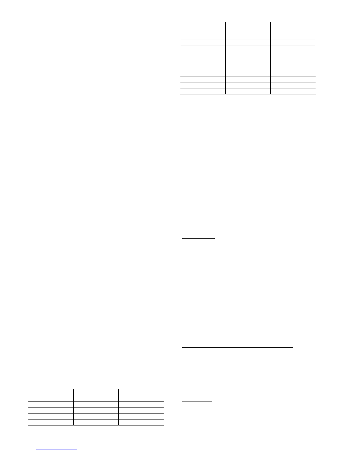
Led Reference Led off Led on
1) 1-2 MOTORI 1 motor automated 2 Motors automated
2) AUT / P -P Automatic Step by step
3) CODE No code Code activated
4) CODE PED. No code Code activated
5) INB.CMD.AP Disabled Enabled
6) PED/ANTA S. Pedestrian Single wing
7) MANT. PRESS. Disabled Enabled
8) SERR. ON PED. Disabled Enabled
9) RALLENTAM. Disabled Enabled
10) SPUNTO INIZ. Disabled Enabled
11) COLPO ARIETE Disabled Enabled
12) PRELAMP. Disabled Enabled
13) T. MOT. Unlimited timing Programmed delay
14) T. PAUSA. No automatic close With automatic close
15) RIT. ANTE AP No wing delay Programmed delay
16) RIT. ANTE CH No wing delay Programmed delay
17) POWER Central ON Central OFF
1) 1 – 2 MOTORS:
For installation, the centre has 2 preinstalled configurations
for the automation of 1 or 2 mot ors.
The default configuration offers control of one motor (sliding
gate for example). If needed, predefined control of 2 motors is
set in the following way: set the SEL button on the 1-2
MOTORS flashing Led, then press MODE button, and Led 1 -2
MOTORS will remain lit and the operation will be completed.
Follow this procedure to return the previous setting.
2) Automatic\Step by step:
The centre in its default setting shows the automatic working
function set (Led AUT/P-P is off). To set the step by step
function (Led AUT/P-P is on): set the SEL button on the AUT/PP flashing Led, then press the MODE button. Led AUT/P-P will
remain lit. Repeat the operation to return to the previous
setting.
3) CODE: (Radio control code)
The board allows the memorisation up to 120 radio
commands having different codes, which are either fixed or
rolling code.
Programming.
The transmission code is programmed in the following
manner: press the SEL button until the CODE led flashes,
immediately transmit the pre-selected code with the desired
remote control, in the moment in which the led CODE remains
accessible, the programming, will be complete When all 120
codes have been stored in the memory all the Led lights will
flash, signalling that nothing else can be stored..
Programming through Radio command.
This procedure, consents to enable the programming, without
direct intervention of the SEL task on the panel, but executing
the operation at a distance, allows the programming of
transmission codes without the having to use the SEL button
on the central direct. The ability of programming is executed in
the following manner: send in a continuous manner for max.
10 seconds the codes of the radio command previously
memorised, at the same time the panel will enter into
programming mode as explained above.
Ability of programming through Radio command.
The panel is furnished by the builder with the radio command
disabled, if you wish to enable the function, proceed in the
following manner: the panel board is powered by an output of
230VAC, keeping the SELL task pressed, at the same time
you will obtain a brief flashing of all the Leeds and the
programming will be complete.
If you wish to disable the function previously enabled, repeat
the operation or follow the RESET procedure.
Cancellation.
All the transmission codes are cancelled in the following
manner: press the SEL button until the CODE led flashes,
then press the SET button and the CODE Led will be turned off
and the cancellation will be completed.
Page 3

4) CODE PED:(Radio control code Ped. / Anta S.)
The programming procedure is as above, simply use Led
Code PED
5) INB. CMD. AP: (Interrupting commands during opening and
pauses, if set)
The option to interrupt commands during opening and
pauses, if inserted, is used when the automation is detected
by the loop detector. The centre, during the opening phase
and pauses, does not receive commands from the loop
detector at every crossing.
The central in its default setting, offers the interruption of
commands when the gate is opening and during the pause
period. To activate, proceed in the following way: set the SEL
button on the INB.CMD.AP flashing Led, then press the MODE
button and Led INB.CMD.AP will remain lit. Repeat the
process to return to the previous setting.
6) Pedestrian/Single wing:
The central’s default setting has pedestrian access enabled
(Led PED/ANTA S. is off). To set single wing opening (Led
PED/ANTA S. is on): use the SEL button to light the Led
PED/ANTA S., then press the MODE button. Led PED/ANTA S.
will remain lit. Repeat the process to return to the previous
setting.
7) MAINTAINING HYDRAULIC MOTOR PRESSURE :
This option is used to compensate for the loss of pressure
with time. The centre sends a the lock command to close for 2
seconds every 2 hours.
The option is disabled in the default configuration. To active it,
use the SEL button to light Led MANT. PRESS. Then press
MODE. Led MANT. PRESS. Will remain lit. Repeat the
operation to return to the previous setting.
8) Electric lock “ON” button:
The electric lock “on” button is used when available, for
example with a sliding door and a pedestrian door attached.
In this mode it is possible to open the gate or door through
with button commands.
The default setting is lock ON with button input disabled. To
enable it use the SEL button to light the Led SER. ON PED,
then press MODE. Led SER. ON PED with light. Repeat the
operation to return to the previous setting.
9) Slowing-down: (Program. Slowing time 15 sec. max.)
The function slowing the motor is used for shutter gates to
prevent the gates coming together at too high a speed during
the opening and closing phases.
The centre will start to reduce the motor’s velocity for the set
slowing period.
During the closing phase, when the slowing-down is finished,
the centre sends a close signal to facilitate the electric locking.
If electric locking ON with pedestrian input is enabled the
ultimate closing signal will not be executed.
The slowing function is disabled when the centre is in its
default setting. To activate it, use the SEL button to select the
RALLENTAM Led, then press the MODE button for the desired
period. At this point the Led will light. TO disable to function
use the SEL button to select the RALLENTAM Led and press
MODE for less than one second. The Led will go out and the
operation will be be complete.
You are advised to program this setting after you have
programmed the motors.
10) INITIAL MOTOR PICK-UP :
This function is used when a notable reduction in engine
power from the electric clutch is needed. However, this
means that the motor will not have sufficient power to start,
and the engine pick up helps the engine during this initial 3second phase, helping the engine to full power.
The engine pick-up option is disabled in the default setting. To
activate it, press the SEL button to select the Led SPUNTO,
then press MODE: the Led will remain lit. Repeat the
procedure to return to the previous setting.
11) HAMMER OPENING :
This function used with closing gates with closing gates with
an electric lock and helps th e unlocking of the gate during the
opening phase. Before starting the opening phase the unit
sends a closing signal for 2 seconds.
In the default setting this option is disabled. To enable it, use
the SEL button to light Led C.ARIETE, then press MODE. The
Led C.ARIETE will remain lit. Repeat the operation to return to
the original setting.
12) WARNING LIGHT :
This function is used when it is necessary to show in advance
that automated movement will begin.
Before the motor starts, the centre will always light the light for
3 seconds.
In the default setting this option is disabled. To enable it, use
the SEL button to light Led PRELAMP, then press MODE. The
Led PRELAMP will remain lit. Repeat the operation to return to
the original setting.
13) T. MOT: (Programming motor work time, max. 4 mins)
The centre is supplied with a preset motor time of 30
seconds.
If it is necessary to reset the time you must close the units in
the following manner: use the SEL button to light Led TMOT.
Then keep the MODE button pressed. Motor1 will start the
opening phase, and at the desired point release the MODE
button. When Led TMOT flashes rapidly keep the MODE button
pressed. Motor 2 will start the opening phase. Release the
MODE button at the desired point. The work time of the 2
motors is now set: Led TMOT will remain lit and the centre will
return the motors to their original position. If the centre is
programmed for 1 motor, Led 1-2 MOTOR OFF, the
programmed work time for Motor2 will not be followed.
For infinite work time use the SEL button to light Led TMOT
then press the MODE button for less than 1 second. Led
TMOT will go out and the operation will be complete.
14) T. PAUSE: (Maximum programmed automatic wing closing 4
minutes)
The manufacturer furnishes the board with an automatic
closure (pause time equal to 15 sec.). If a reprogramming of
the automatic closing time is needed, it must be effected in
closed frame in the following manner: press the SELL button
until the T. PAUSE led flashes, then press and hold down the
MODE button for a period equal to the desired pause interval
between closing and opening operations, at the expiry of the
desired time leave the MODE button, at the same time the
memorisation of automatic closing time will be determined
and the Led T. PAUSE will be lit.
If decided not to have the automatic closing, take position on
the flash of the Led T. PAUSE after press the MODE task for
Page 4
less than a second, at the same time the Led will shut off and
the operation will be concluded.
15) DELAY IN WING OPENING: (programmed wing delay 15
sec. max.)
The manufacturer furnishes the panel if chosen the
automation of 2 motors with a delay in wing opening equal to
3 seconds (del. MOTOR 2 ).
If a reprogramming of the delay is needed in relation to its
opening, it must be effected during close frame in the
following manner: take position on the SEL, task when the led
WING DELAY OP. is flashing, then press in continuous
manner the MODE task for as long as the time desired,
release the MOD E task, at the same time the memorisation of
the delay will be determined and the Led DELAY WING OP.
will be fixed. If desired not to have a delay in wing opening,
take position on the Led DELAY WING OP. then press MODE
task for less than a second, at the same time the Led will shut
off and the operation will conclude.
16) DELAY IN WING CLOSING: (programmed wing delay 15
sec. max.)
The manufacturer furnishes the panel if chosen the
automation of 2 motors with a delay in wing closing equal to 3
seconds (del. MOTOR 1 ).
If a reprogramming of the delay is needed in relation to its
closing, it must be effected during close frame in the following
manner: take position on the SEL, task when the led WING
DELAY CL. is flashing, then press in continuous manner the
MODE task for as long as the time desired, release the MODE
task, at the same time the memorisation of the delay will be
determined and the Led DELAY WING CL. will be fixed. If
desired not to have a delay in wing closing, take position on
the Led DELAY WING CL. then press MODE task for less than
a second, at the same time the Led will shut off and the
operation will conclude.
17) POWER:
Central feed,
Led POWER
on.
RESET :
If it
necessary to
reset the
program
board to its
default
values, that
is with no
memorised
data, press
both SEL
and MODE
buttons
continuously, all the RED LEDs will flash at once
DIAGNOSTIC :
In corrispondence to all input commands in low tension, the
centre uses Led signals for every input command to allow
rapid status control. Logic of function: a lit Led means input
closed, an unlit light means input open.
Rev. 1.2 del 27-01-03
D ECLARATION OF CONFORMITY
SEAV s.r.l. declares that the products:
Electronic exchange LG 2145 - LRS 2145
Conforms with all of the requirements laid out in the EC
directive number: 99/5 which are based on the following
standards:
- EN 301 489-3 ;
- EN 300 220-3 ;
- EN 60335-1.
The samples which have been tested meet the essential
requirements which have been specified above, on the
basis of the results of the tests.
 Loading...