

Page 1
Operator’s Manual
CA11
11 Column
LIMITED WARRANTY
Seaga warrants to the original purchaser that the equipment is free from defects in material and factory workmanship for a period of one (1) year from date of shipment.
Repair or replacement of proven defective parts is limited to manufacturing defects demonstrated
under normal use and service during warranty period. Prior to returning any parts with transportation
charges prepaid for replacement, the customer is to contact Seaga's Customer Care Department at
815.297.9500 and be assigned an RA number. Seaga will refuse any collect shipment. To obtain an
RA number, contact Seaga with complete information including the serial number(s), date of purchase and description of the part and/or suspected defect to:
Seaga Manufacturing, Inc.
700 Seaga Drive
Freeport IL 61032
We may also be contacted, with complete information, as follows:
phone: 815.297.9500
fax: 815.297.1700
email: [email protected]
Seaga will repair or replace, at our option, any covered part which meets the provisions herein during the warranty period. It is our discretion to replace defective parts with remanufactured parts.
Seaga reserves the right to make changes or improvements in its products without notice and without obligation, and without being required to make corresponding changes or improvements in equipment already manufactured or sold.
This warranty applies only if the equipment has been serviced and maintained in strict accordance
with the instructions presented in the Operator's Manual and no unauthorized service, repair, alteration or disassembly has been performed. Any defects caused by improper power source, poor water
quality or pressure, an installed water filtration system not fully functioning, abuse of the product,
accident, alteration, vandalism, improper service and maintenance schedules, neglecting to de-scale
and sanitize on a regular basis, use of products or ingredients not allowed in the machine, corrosion
due to use of non-approved detergents or cleaning solutions, or damage incurred during return shipment will not be covered by this warranty. Further, equipment that has had the serial number
removed, altered or otherwise defaced will not be covered by this warranty.
Lighting components, refrigerant, glass, paint, decals, fuses, filters or hygiene replacement parts,
labor and/or installation are not covered by this warranty.
Follow proper maintenance procedures and use of equipment, as described in the Operator's Manual
provided on Seaga's web site at seagamfg.com, which include but are not limited to:
* Cleaning of equipment including regular maintenance
* Proper installation and location of equipment with respect for the indicated
temperature and humidity levels
* Proper use of equipment including loading, programming and setup
THIS WARRANTY IS IN LIEU OF ALL OTHER WARRANTIES, EXPRESSED OR IMPLIED, TO
INCLUDE, BUT NOT LIMITED TO, WARRANTIES OF MERCHANTABILITY AND FITNESS FOR A
PARTICULAR PURPOSE AS T O THE UNIT AND ACCESSORIES. UNDER NO CIRCUMSTANCES
SHALL SEAGA BEAR RESPONSIBILITY FOR ANY INCIDENTAL, CONSEQUENTIAL, PUNITIVE
OR SPECIAL LOSSES OR EXPENSES. Seaga neither assumes nor authorizes any person to
assume for it any obligation or liability in connection with the sale of said unit(s) or any part(s)
thereof.
SMI2455562
Page 2
2
700 Seaga Drive
Freeport, IL 61032 U.S.A.
Online: seagamfg.com
INTRODUCTION
Congratulations on the purchase of your new Snack Vendor. This Snack Vendor
has been designed to give you many years of dependable service. It requires little
maintenance and is easy to set up and operate.
READ THIS MANUAL
COMPLETELY
Your Snack Vendor is designed to operate simply and reliably, but to take full
advantage of your vendor, please read this owner's manual thoroughly. It contains
important information regarding installation and operations, as well as a brief troubleshooting guide.
EQUIPMENT INSPECTION
After you have received your Snack Vendor and have it out of the box, place it on
a secure surface for further inspection. Note: Any damages that may have
occurred during shipping must be reported to the delivery carrier immediately.
Reporting damages and the seeking of restitution is the responsibility of the equipment owner. The factory is willing to assist you in this process in any way possible.
Feel free to contact our Customer Care Department with any questions you may
have on this process. It is important that you keep the original packaging for your
vending machine at least through the warranty period. If your machine needs to be
returned for repair, you may have to purchase this packaging if it is not retained.
Once you have your vendor located, we suggest that you keep this manual for
future reference, or you can view this manual online at seagamfg.com. Should any
problems occur, refer to the section entitled “COMMON QUESTIONS AND
ANSWERS”. It is designed to help you quickly identify a problem and correct it.
For T
echnical Support & Service
Contact our Customer Care Dept.
8:30 a.m. - 4:00 p.m. CST. Mon thru Fri
815.297.9500 ext 160
815.297.1758 Fax
email: [email protected]
For Parts
Contact our Parts Dept.
8:30 a.m. - 4:00 p.m. CST. Mon thru Fri
815.297.9500 ext 160
815.297.1758 Fax
email: [email protected]
15
Page 3
3
CA11
11 Column
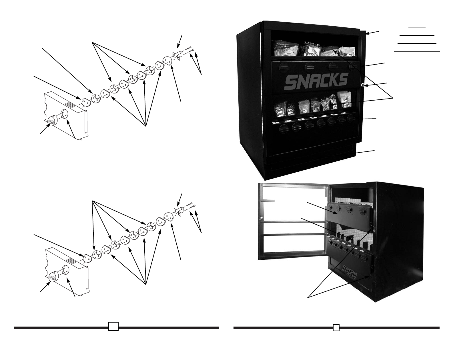
Mechanical
Snack Vendor
Mechanism
Panel
Lock
Front Door
Coin Mechanism
Knob
Product
Window
Product
Opening
Coin Box
Mechanism Panel
Product Tray
14
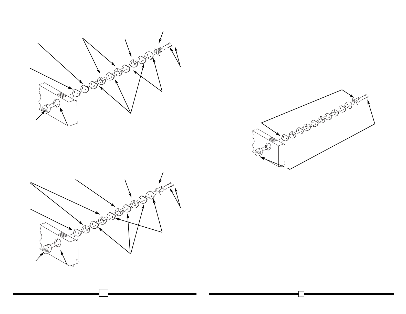
Figure 13 Optional $.80 configuration
Knob
PL104
Mechanism
Panel
Ratchet Disc
ST103
Quarter Disc
ST105
White Spacer
ST108
Driver
ST110
Screws
SS112
Nickel Disc
ST106
Black Spacer
ST104
Figure 14 Optional $1.00 configuration
Knob
PL104
Mechanism
Panel
Ratchet Disc
ST103
Quarter Disc
ST105
White Spacer
ST108
Driver
ST340
Screws
ST112
Black Spacer
ST104
Page 4
LOCKS
Your CA11 Vendor has one (1) screw type Lock. To unlock the Front Door, unscrew
the Lock counter clockwise until the door is free. To lock, apply firm pressure below
the Lock as you tighten the Lock. Do not over tighten as you could ruin the seal. You
will be able to remove the key, only when the key is vertical or horizontal.
DELIVER
Y SYSTEM
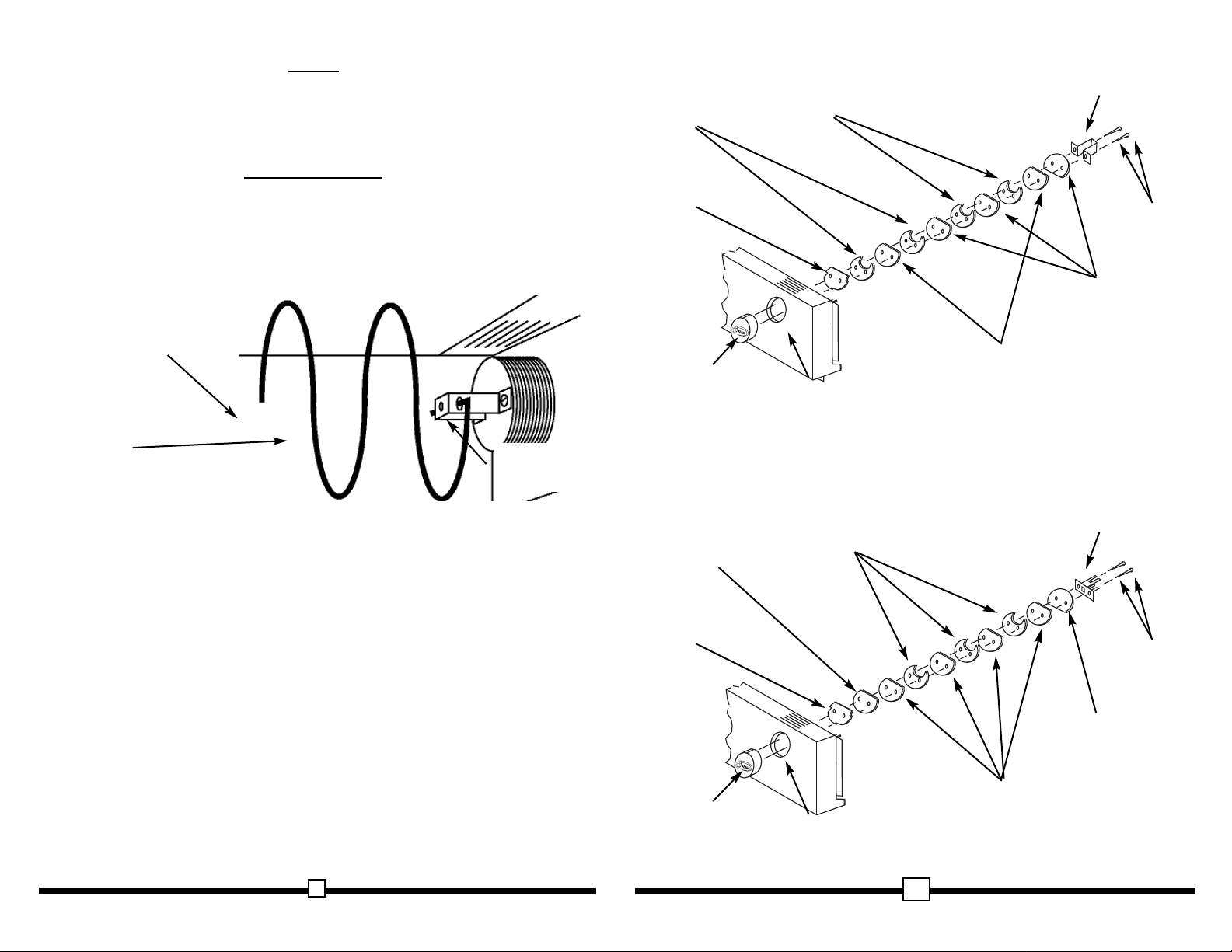
Your new CA11 features a rear-drop delivery system to prevent theft.
The CA11 delivery system is made up of three (3) components, the Product Tray, the
Helix Coils, and the Coin Mechanism (Fig. 1). Once the proper amount of coins is
received the Coin Mechanism drives the Helix Coil and pushes the product out the
back of the Product Tray.
13
4
Figure 11 Optional $.70 configuration
Knob
PL104
Mechanism
Panel
Ratchet Disc
ST103
Quarter Disc
ST105
White Spacer
ST108
Driver
ST110
Screws
SS112
Black Spacer
ST104
Dime Disc
ST107
Figure 12 Optional $.75 configuration
Knob
PL104
Mechanism
Panel
Ratchet Disc
ST103
Quarter Disc
ST105
White Spacer
ST108
Driver
ST110
Screws
SS112
Black Spacer
ST104
Black Spacer
ST104
Figure 1 Delivery System
Driver
Mechanism
Helix Coil
Product Tray
Page 5
DRIVER MECHANISM
The Mechanism Panels are the front upper and lower panels. These panels control
the receiving of money and the action of the Helix Coil. Once the correct amount of
money is received, the Mechanism Knob can be turned clockwise. Product is vended
by turning the Mechanism Knob one (1) complete revolution.
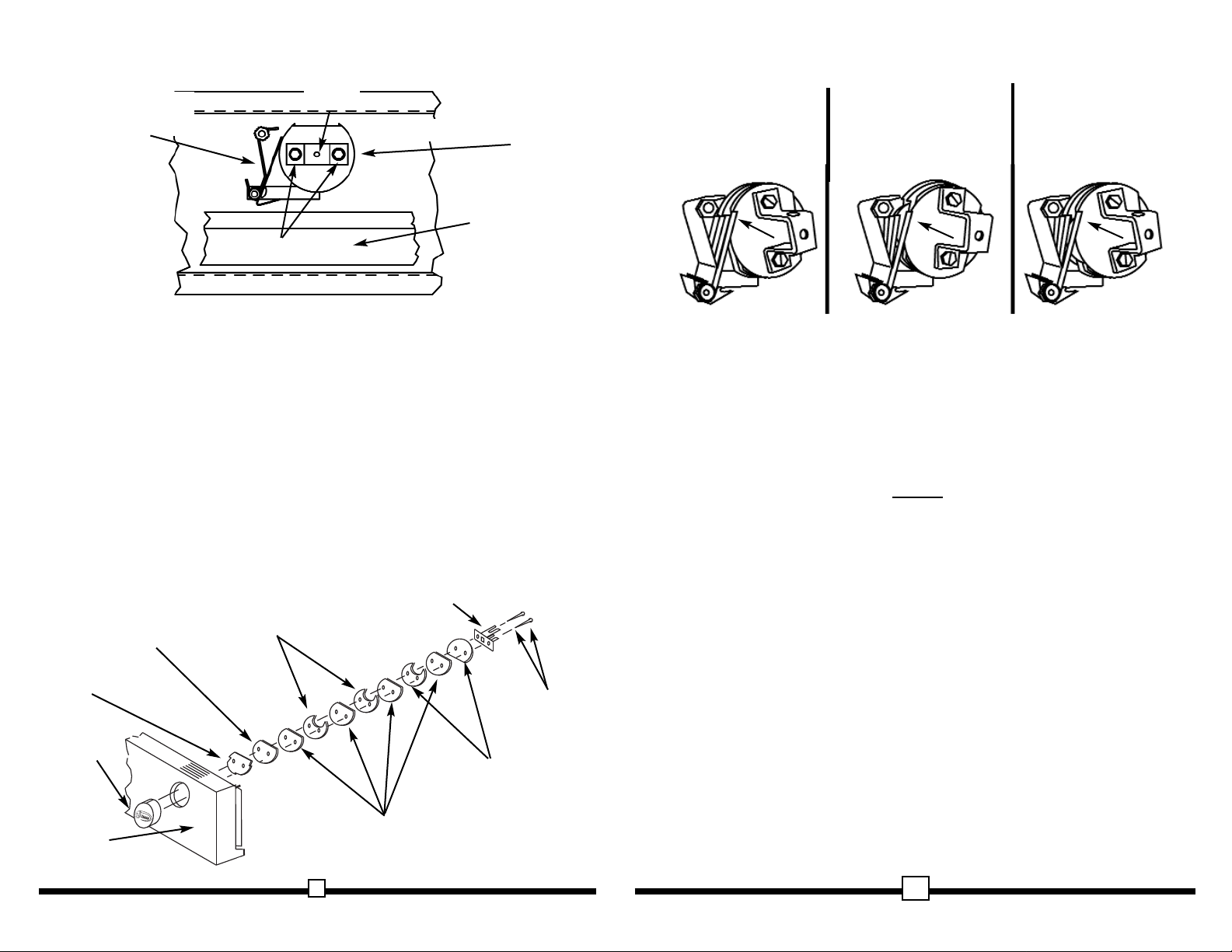
The Driver Mechanism (Fig. 2) comes factory preset but can be changed to suit your
needs. The Coin Sub-Assembly is made up of a series of discs consisting of white,
black and metal Coin Discs. The white spacers are thinner than the black, and the
combination of the two place the Coin Discs in the proper position to receive coins.
In some cases you will find all one (1) color of spacers. This is common in an all-quarter configuration. Contact our Customer Care Dept. for additional instructions on
changing your Coin Sub-Assembly if necessary.
1.To access Coin Mechanism:
A.) Unlock and remove Front Door.
B.) Remove the Mechanism Panel by first removing the two (2) Silver Screws
on both sides of the Mechanism Panel.
C.) Pull the Mechanism Panel outward. Carefully free Drivers from all
Helix Coils.
D.) Turn desired Mechanism Knob clockwise ¼" turn and place Mechanism
Panel face down on a flat surface, exposing the Driver Mechanism
and "S" bracket assembly. (Fig. 3)
Note: Change one Driver Mechanism at a time.
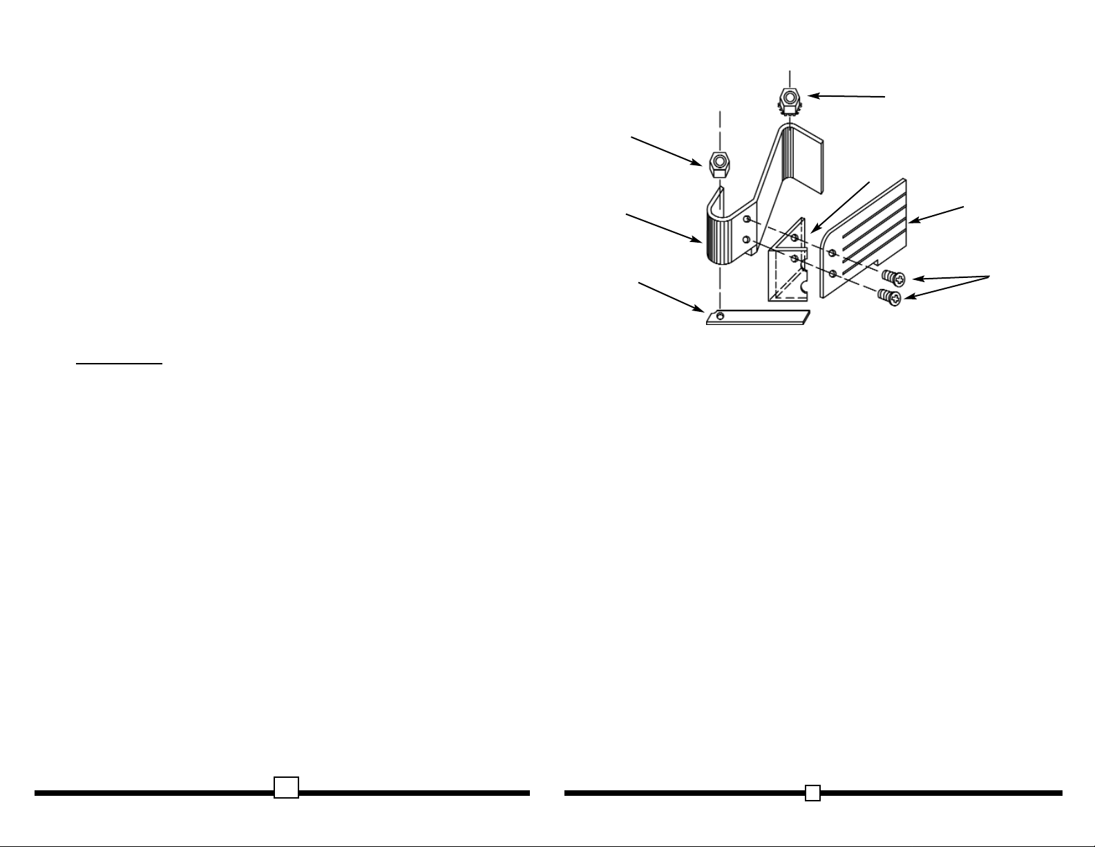
E.) To change Driver Mechanisms, remove two (2) nuts (Fig. 6) and
gently remove "S" Bracket Assembly.
F.) Unscrew and remove the two (2) Screws holding Driver to the Coin
Sub-Assembly. (Fig. 3 & 4)
5
12
Figure 9 Optional $.60 configuration
Knob
PL104
Mechanism
Panel
Ratchet Disc
ST103
Quarter Disc
ST105
White Spacer
ST108
Driver
ST110
Screws
SS112
Black Spacer
ST104
Black Spacer
ST104
Dime Disc
ST107
Figure 10 Optional $.65 configuration
Knob
PL104
Mechanism
Panel
Ratchet Disc
ST103
Quarter Disc
ST105
White Spacer
ST108
Driver
ST110
Screws
SS112
Black Spacer
ST104
Dime Disc
ST107
Nickel Disc
ST107
Figure 2 Driver Mechanism reference
From Knob to Driver is
the “Driver Mechanism”
All discs are the
“Coin Sub-Assembly”
Page 6
Q: What can I use to clean the outside of my vendor?
A: A lint free rag and a mild window cleaner are recommended.
Be sure however not to directly spray decals as the ink could run.
Q: How do I remove a Lock that won’t open.
A: Drill into the center of the Lock with a 1/4” drill bit. The Lock should fall apart
and be easily removed. Increase the bit size and try again if the Lock
does not come out.
NOTES
11
6
G.) Coin Sub-Assembly (Fig. 4) will come apart from Knob, and can be
carefully removed.
2. To assemble Driver Mechanism:
A.) Lubricate backside of Mechanism Panel around holes with a small
amount of petroleum jelly.
B.) Insert two (2) screws through Coin Sub-Assembly to Knob. Make sure
Knob is seated properly and tighten screws into place. If handle is
hard to turn, loosen the two (2) screws
1
/
8 to ¼ turn.
C.) Turn mechanism Knob to align Coin Discs with "S" bracket mounting
studs. Install "S" bracket assembly over mounting studs. Do not
install the nuts yet.
D.) Now turn Mechanism Knob so Coin Disc slots are facing down. The
Anti-Reverse Dog can now be raised enough to enable the
Figure 3 Inside view of Driver Mechanism
“S” Bracket
Assembly
Coin
Deflector
Driver Mechanism
Driver
Screws
Figure 4 Driver Mechanism exploded view
Knob
PL104
Mechanism
Panel
Ratchet Disc
ST103
Quarter Disc
ST105
White Spacer
ST108
Driver
ST110
Screws
SS112
Black Spacer
ST104
Black Spacer
ST104
Standard
$.50 configuration
shown
Figure 8 Coin Rejecter Fingers
Figure 9a Caught!
Empty Coin Discs should
catch on the center of the
Coin Rejector fingers.
Figure 9b Accepted!
Coins should push the
fingers out. Make sure
coins contact the center
of the fingers.
Figure 9c Vend!
Accepted coins push the
fingers over the Coin
Discs’ catches to vend.
Page 7
screw threads. If this does not remedy the problem a replacement
Knob may be needed.
Q: My mechanism rotates backward.
A: Your Knob should not do this. Remove the Mechanism Panel and check for
proper placement and condition of the Anti-Reverse Dog.
Q: My mechanism rotates but product will not drop.
A: Check to see if the product is jammed in the Column.
Check to see if the vendor is level.
Check product for damage, and make sure it is the proper size.
Q: My knob turns ¼" turn and jams.
A: First remove your Mechanism Panel. Check the position of the coins to see if
they are in-between the Coin Rejecter fingers. If this is the case,
place a screwdriver in-between the Coin Rejecter and the discs and
lift up freeing the Coin Rejecter. At this point the Driver Mechanism
can now be rotated backwards. Reposition the Coin Rejecter fingers
with your screwdriver to line up with coins and vend through. (Fig. 8)
GENERAL
Q: Can customers reach up and help themselves to product?
A: No. The Vendor pushes product out the back of the Product Trays, also
Product Door is a Triangle shape designed to deter reach up theft.
When pushed, the back of the door will come in contact with the
bottom Product Tray to act as a block.
Q: My key won't turn my Lock to open.
A: Check to be sure that you are using the proper key. If the correct key is being
used, your Lock may have been damaged or vandalized. Vandalism
to locks is quite common. Having spare Locks in your toolbox at all
times is recommended.
Anti-Reverse Dog Spring to seat under the Anti-Reverse Dog. At the
same time the "S" bracket assembly will be seated against
Mechanism Panel. Place Keps Nut on upper mounting stud. (DO
NOT TIGHTEN NUTS.) (Fig. 3, Pg. 6 and Fig. 5)
E.) Turn Knob to align coin discs with "S" bracket assembly, once again. Use
a screwdriver to push top of "S" bracket assembly fully to right and
tighten Keps Nut. You may now tighten Nylon Threaded Nut to lower
mounting stud. (DO NOT OVER TIGHTEN.)
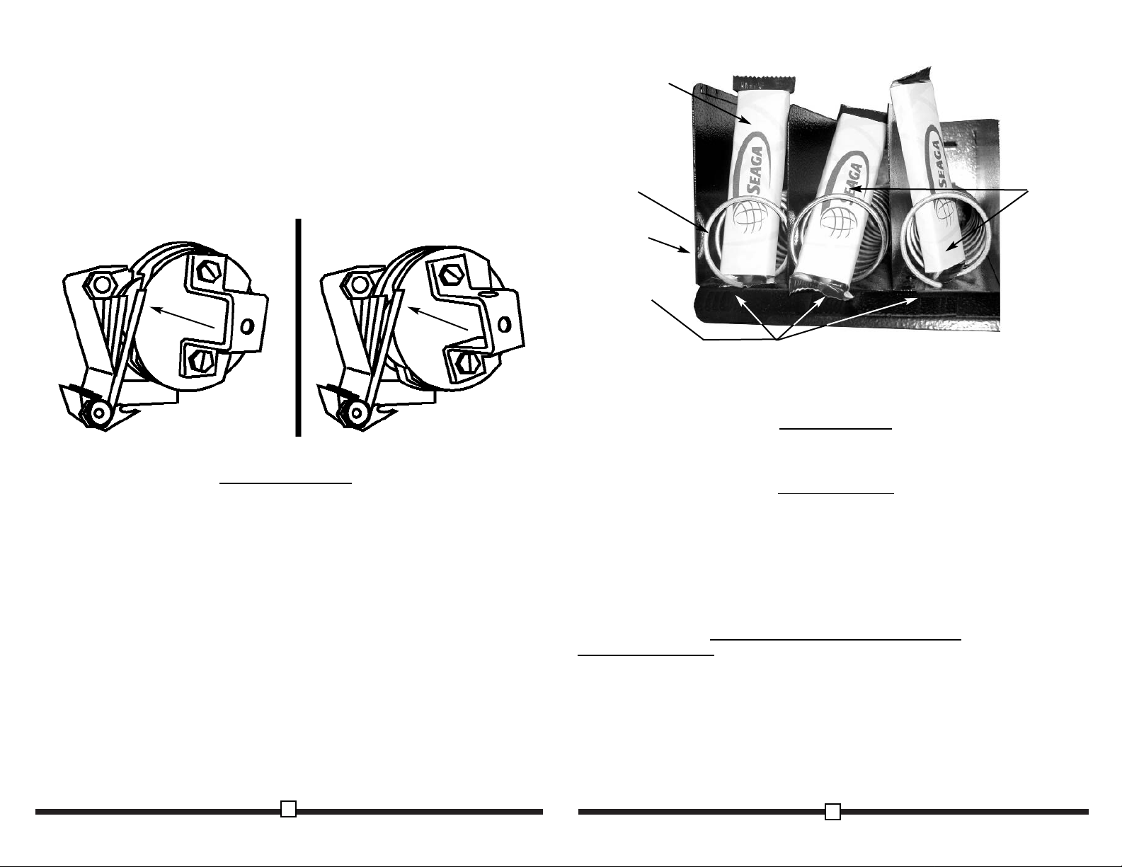
Note: The fingers of the Coin Rejecter must align with Coin Discs of the Coin SubAssembly. The Coin Discs strike the center of each finger to prevent vending without
coins. This alignment is critical. If the fingers are misaligned the vendor will not
vend. (Fig 6)
F.) Check to see that "S" bracket assembly is firmly seated against
Mechanism Panel and upper mounting stud. Check that
Anti-Reverse Dog Spring is engaged on Anti-Reverse Dog. Make
sure Anti-Reverse Dog moves freely and locks into Ratchet Disc as
the mechanism is rotated counter-clockwise. If Anti-Reverse Dog
does not move freely, loosen Nylon Threaded Nut on the lower
mounting stud. If this does not help, remove "S" bracket assembly
and close Anti-Reverse Dog Spring to put more pressure on
Anti-Reverse Dog. Check that coin discs are properly aligned with
the Coin Rejecter by inserting money through slots in the top of the
Mechanism Panel. Make sure the Coin Rejecter is properly engaging
the coin disc stops. (Improper alignment will allow coins to slip
between slots in the Coin Rejecter.)
7
10
Figure 5 “S” Bracket Assembly
Keps Nut
SS206
Nylon
Threaded
Nut
SS207
“S” Bracket
ST201
Anti-Reverse
Dog
PL204
Anti-Reverse
Dog Spring
ST203
Screws (2)
SS914
Coin Rejecter
ST202
Page 8
9
8
Refer to the optional mechanism configurations at the end of this manual. Always make
sure your Driver Mechanism is built as specified in the diagram. Note: The disc next to
the Driver is always placed upside down (the rounded side will be at the top of the disc
only) to prevent coins from jamming the mechanism.
LOADING PRODUCT
To present your product in as an attractive and professional manner as possible, do
not load any damaged items, and make sure items are facing forward for easy
identification by your customer.
Note: The size of the item being vended must be larger than the Helix Coil, but
smaller than the Column, to vend correctly. Never force an oversized item into the
Helix Coil or Column, nor attempt to vend an item that is smaller than the Helix Coil
as this will create problems and deter customers.
1. To Load Product:
A.) Pull desired Product Tray forward. Note: Pull out only one (1) Product
Tray at a time.
B.) Place product in proper size Helix Coil. Note: Bottom of product must rest
on the Product Tray and not on the Helix Coil. (Fig.7) Load each
Helix Coil from back to front. Note: Fill all Helix Coils fully, do not
leave any empty spaces behind or between items. If you must leave
empty space leave it in the front of the Tray closest to the
Product Window.
C.) Once Product Tray is fully loaded, lift and push it back in. Repeat above
steps until both Product Trays are fully loaded.
Special Note: We suggest that you always partially fill the vendor with product and
perform at least five (5) test vends.
COIN
RETRIEVAL
Two (2) Coin Boxes are provided with your CA11. They are stored inside the
Mechanism Panel directly below the Coin Mechanisms. Once the Front Door is open
pull the Coin Boxes out to the right to empty them.
GENERAL
NOTES
It is suggested that a tool box accompany you to each of your locations. Suggested
items for this tool box would include a socket set, (up to a
1
/2" socket size suggested)
a Phillips and a Standard screwdriver. Additional items would be a small jar of
Petroleum Jelly (Vaseline), a small brush for applying the Petroleum Jelly, a soft rag
and perhaps a Black Magic marker. The magic marker is useful in touching up light
scratches that may occur to your vendor.
COMMON QUESTIONS
AND ANSWERS
MAINTENANCE
Q: My knob turns without coins.
A: Your Coin Rejecter is loose, misaligned or broken. Refer to the Driver
Mechanism section of this manual for proper placement of
the Coin Rejecter. (See Fig. 5 & Fig. 8)
Q: My mechanism screws keep coming loose.
A: Remove Mechanism Panel. Disassemble Knob. Apply lock tight to Knob
Figure 6 Proper Finger Alignment
Figure 6a Accepted!
Coins should push the fingers out.
Make sure coins contact the
center of the fingers.
Figure 6b Vend!
Accepted coins push the
fingers over the Coin
Discs’ catches to vend.
Figure 7 Loading Product
Correct - load
product between
Helix Coils,
resting on the
product tray
Incorrect
Product Tray
Columns
Helix Coil
 Loading...