

®
Sistemi Elettronici
di Apertura Porte e Cancelli
International registered trademark n. 804888
Italiano
English
USER 2 - 24V DG
“ALL IN”
23024040/45/48
APPAR. ELETTRONICA 24V PER CANCELLI A BATTENTE
ELECTRONIC CONTROL UNIT 24V FOR SWING GATES
ARMOIRE ELECTRONIQUE 24 V POUR PORTAILS A BATTANTS
TARJETA ELECTRONICA 24V PARA CANCELA ABATIBLES
Français
Español
SEA S.p.A.
Zona Ind.le S. Atto - 64020 S. Nicolò a Tordino (TE)
Tel. 0861.588341 - Fax 0861.588344
www.seateam.com
e-mail: seacom@seateam.com
REV 01 - 11/201367411655
Sistemi Elettronici
di Apertura Porte e Cancelli
International registered trademark n. 804888
®
USER 2 - 24V DG
“ALL IN”
CONNESSIONI / CONNECTIONS / CONNEXIONS
CONEXIONES / VERBINDUNGEN
ATTENZIONE: la scheda è predisposta con il riconoscimento automatico degli ingressi N.C. non utilizzati
(fotocellule, Stop e finecorsa) ad eccezione dell’ingresso COSTA DI SICUREZZA.
WARNING: The control unit is designed with the automatic detection of not used N.C. inputs (photocells,
Stop and Limit switch) except the SAFETY EDGE input.
AVERTISSEMENT: L'armoire est conçue avec la détection automatique des accès N.C. pas utilisés
(photocellules, Stop et fins de course), à l'exception de l'accès BARRE PALPEUSE DE SECURITE.
ATENCIÓN: la tarjeta está predispuesta con el reconocimiento automático de las entradas N.C. no
utilizados, fotocélulas, stop y fin de carrera, con excepción de la entrada COSTA DE SEGURIDAD.
ACHTUNG: Die Steuerung ist mit der automatischen Erkennung der nicht verwendeten N.C. Eingänge,
ausgestattet (Lichtschranken, Stop-und Endschalter) ausgenommen des Sicherheitsleiten Eingangs.
Lamp.(-) / Flash (-)
13
Blinklampe (-)
Lampe (-) / Lámpara (-)
12
24VL (Lamp.) / 24VL (Flash)
24VL (Blinklampe)
24VL (Lampe) / 24VL (Lámpara)
11 10
Max 600 mA
Comun / Común
Comune / Common
24V Aux
Gemeinsam
CN2
(250 mA max)
Costa / Edge / Tranche /
9 8
Sicherheitsleiste
Banda de seguridad /
Fotocellula 2/ Photocell 2
Lichtschranke 2
Photocellule 2 / Fotocélula 2
CN1
7 6
Lichtschranke 1
Fotocellula 1/ Photocell 1
Photocellule 1 / Fotocélula 1
RADIO MODULE (CNA)
5
4
3
2
1
Connettore modulo ricevente
Receiver module connector
Connecteur module récepteur
Conector modulo receptor
Verbindungsmodul Empfänger
JOLLY
Stop
Gemeinsam
Comun / Común
Comune / Common
START Ped./ START Ped.
Start
Antenne
START Fuss.
Gemeinsam
Comun / Común
Comune / Common
Antenne / Antena
Antenna / Antenna
CN5
START Piéton / START Peat.
Connettore Programmatore Jolly
Connector Programmer Jolly
Connecteur Programmateur Jolly
Conector Programador Jolly
Anschluss Programmierer Jolly
CN3
2
15
14
M1/
a
r
tu
rF
e
ap
a
rs
o
nec
i
1
M
ng
eni
p
o
L
tch
wi
t S
i
m
i
/
1h
1
g M
a M
r
u
sin
o
c
chius
c l
t
a
i
s
w
S
it
ecor
n
m
i
F
Li
16 17
/
2
M2
M
ing
ura
t
r
pen
pe
o
a
h
a
tc
i
w
S
t
i
necors
m
Fi
Li
EXP
Connettore Modulo Esterno
Connector External Module
Connecteur Module Extérieur
Conector Modulo exterior
Anschluss Aussenmodul
67411655
/F n a
ra
i s M2
c u u
h
s
or
c
i e
2
ML
i
os
l ng
c
h
t
i c
S
imi w
t
18 19
Gemeinsam
Comun / Común
Comune / Common
S
+
-
23
24
25 26
20
a
í
ery
t
ter
at
b
Ba
e
v
tivo
siti
Electric lock /
Elektroschloss
Electro-serrure /
Elettroserratura /
Electrocerradura /
(12V 15VA max)
28V Caricabatterie
28V Cargabaterias
28V Battery charger
28V Batterieladegerät
28V Chargeur de batterie
si
Po
/Po
a/
i
rie
e
ter
t
t
at
b
f ba
o
i
v
i
t
sit
i
os
Po
P
PROG
Connettore programmazione
Programming
Connecteur p
Conector programación
Anschluss für die Programmierung
REV 01 - 11/2013
connector
rogrammation
a
e
i
er
ri
g
e
er
tt
ar
a t
h
b
c
c
v Ba
ery
siti
c r a t
a t
a i
b
Po
e
tiv
v
i
a
t t
g o
ga
Ne
e
N
t
s
rie
rä
ía
e
e
tt
t r
a
eg
a e
b
r
a
lad
u b
g
uf
e
a
rg
car
rie
ha
vo
te
t
ti
tif c
ga
e
ga
e
tiv Ba
N
a
N
g
Ne
POWER
Connettore alimentazione 24V~
24V~ Power connector
Connecteur alimentation 24V~
Conector alimentaci n 24V~
Speisungsverbindung 24V
M1 M2
ó
~

Sistemi Elettronici
di Apertura Porte e Cancelli
International registered trademark n. 804888
®
English
USER 2 - 24V DG
“ALL IN”
INDEX
DESCRIPTION OF THE COMPONENTS...................................................................................25
GENERAL INFORMATION .........................................................................................................26
QUICK START ............................................................................................................................27
SELFLEARNING WORKING TIME.............................................................................................28
SELECTION OF SETTINGS.......................................................................................................29
RADIO TRANSMITTER SELF LEARNING WITH RECEIVER ON BOARD OF CONTROL
UNIT ...........................................................................................................................................36
DELETE TRANSMITTERS .........................................................................................................36
FUNCTIONING LOGICS.............................................................................................................37
PASSWORD ENTERING MANAGEMENT .................................................................................37
START, STOP, PEDESTRIAN START, ANTENNA, PHOTOCELL CONNECTIONS ..................38
AMPEROMETRIC MANAGEMENT, ELECTRO-LOCK, WARNING LAMP,
EDGE CONNECTIONS ..............................................................................................................39
LIMIT SWITCH, EXTERNAL RECEIVER CONNECTIONS .......................................................40
POWER SUPPLY AND MOTORS CONNECTIONS ...................................................................41
CONNECTION OF BATTERIES .................................................................................................42
TRAFFIC LIGHT CARD CONNECTION .....................................................................................42
ALARMS INDICATIONS, ALARM SIGNALS...............................................................................43
TROUBLE SHOOTING ...............................................................................................................44
WARNING, MAINTENANCE AND WARRANTY .........................................................................44
24
REV 01 - 11/201367411655
Sistemi Elettronici
di Apertura Porte e Cancelli
International registered trademark n. 804888
®
English
USER 2 - 24V DG
“ALL IN”
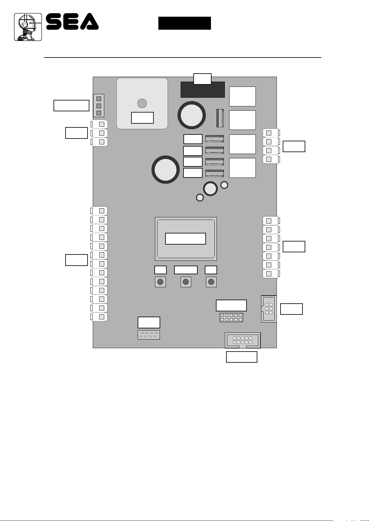
DESCRIPTION OF THE COMPONENTS
F1
RL1
POWER
CN5
CN1
+ S -
13 12 11 10 9 8 7 6 5 4 3 2 1
PR1
MF4
MF3
MF2
MF1
RL2
RL3
RL4
CN3
23 24 25 26
DISPLAY
CN2
UP DOWN OK
14 15 16 17 18 19 20
CNA
CN1 = Input/Output connector
CN2 = Limit switch, electro-lock connector
CN3 = Motors connector
CN5 = Battery charger connector
CNA = Receiver module connection
EXP = External module connector
JOLLY = Jolly programmer connector
PROG
EXP
JOLLY
MF1 - MF2 = Mosfet motor 2
MF3 - MF4 = Mosfet motor 1
POWER = 24V~ power supply connection
PROG = Programming connector
Pr1 = Rectifier jumper
RL1 - RL2 = Relay motor 2
RL3 - RL4 = Relay motor 1
F1 = Fuse 10AT
67411655
REV 01 - 11/2013
25
Sistemi Elettronici
di Apertura Porte e Cancelli
International registered trademark n. 804888
®
English
USER 2 - 24V DG
“ALL IN”
GENERAL INFORMATION
The information in this section of the manual are only for technicians or for qualified or authorized
installers.
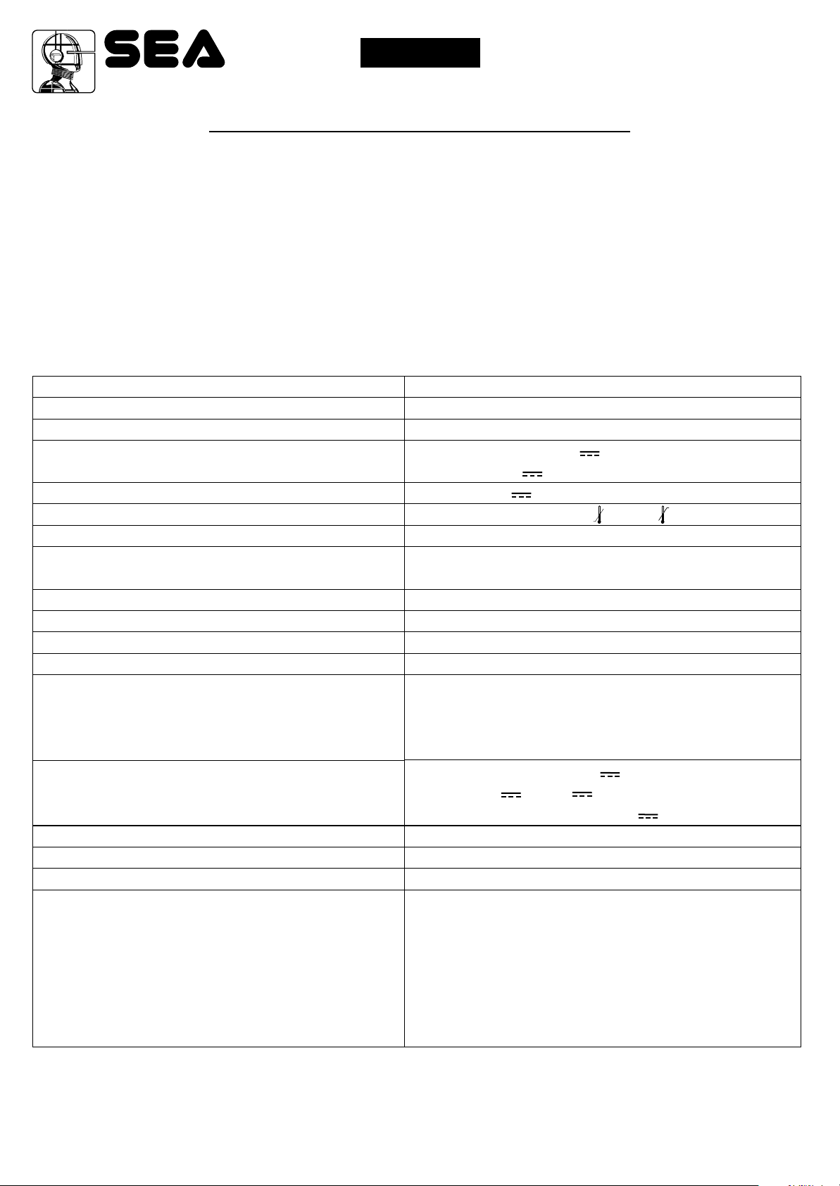
GENERAL CHARACTERISTICS
The USER 2 24V DG “ALL IN” control unit has been designed to manage one or two low voltage swing gate
operators with or without electronic limit switches.
It is of very small dimensions and besides the possibility to adjust motor speed, amperemetric anti squeezing
sensitivity, leaf delay in closing, pausing time, it is also possible to manage a display, through which it is possible to
control a lot of management functions and the maintenance of the control unit.
TECHNICAL SPECIFICATIONS
Control unit power supply
Absorption in stand by
Max. motor charge
Max. accessories charge
Max. Flash light charge
Environment temperature
Protection fuse
Function logic
Opening/closing time
Time of pause
Thrust
Slow down
Input on connecting terminal
Output on connecting terminal
Board dimensions
Specifications of optional batteries
Specifications of external enclosure
Special accessories
24V~
30mA
150 W x 2
24Aux (250mA) (Programmable) /
24VL (600mA) (Accessories and Flashing lamp)
24VL (Flashing lamp) 15W max.
-20°C +50°C
10AT
Automatic / Step by step type 1 / Step by step type 2
/ Safety / Dead man / 2 Buttons.
In selflearning in programming phase
Adjustable
Adjustable for single leaf and direction
Adjustable for single leaf and direction
Battery power supply / Total opening / Pedestrian
opening adjustable / Edge (opt.8K2)/
Stop / Limit switch opening and closing / Encoder /
Photcell in opening and closing
Power supply 24Aux (Programmable) /
Motors 24V / 24VL Accessories and Flashing
lamp / Electro-lock 12V 15VA Max
156 x 100 mm
24V Pb 2Ah min.
305 x 225 x 125 mm - Ip55
Battery charger card (code 23101105)
Relay card for traffic light management
(SEM Cod. 23021100)
Programmer JOLLY (code 23105276)
Programmer JOLLY2 (cod.23105277)
Programmer OPEN (code 23105290)
Display BINGO (cod.23101131)
NOTE: The Jolly programmer will be functioning starting from Rev. 35 onwards. You can upgrade the
software of the Jolly and the control units with the OPEN device and the update firmware software.
The herein reported functions are available starting from revision 018.
26
67411655
REV 01 - 11/2013
Sistemi Elettronici
di Apertura Porte e Cancelli
International registered trademark n. 804888
®
English
USER 2 - 24V DG
“ALL IN”
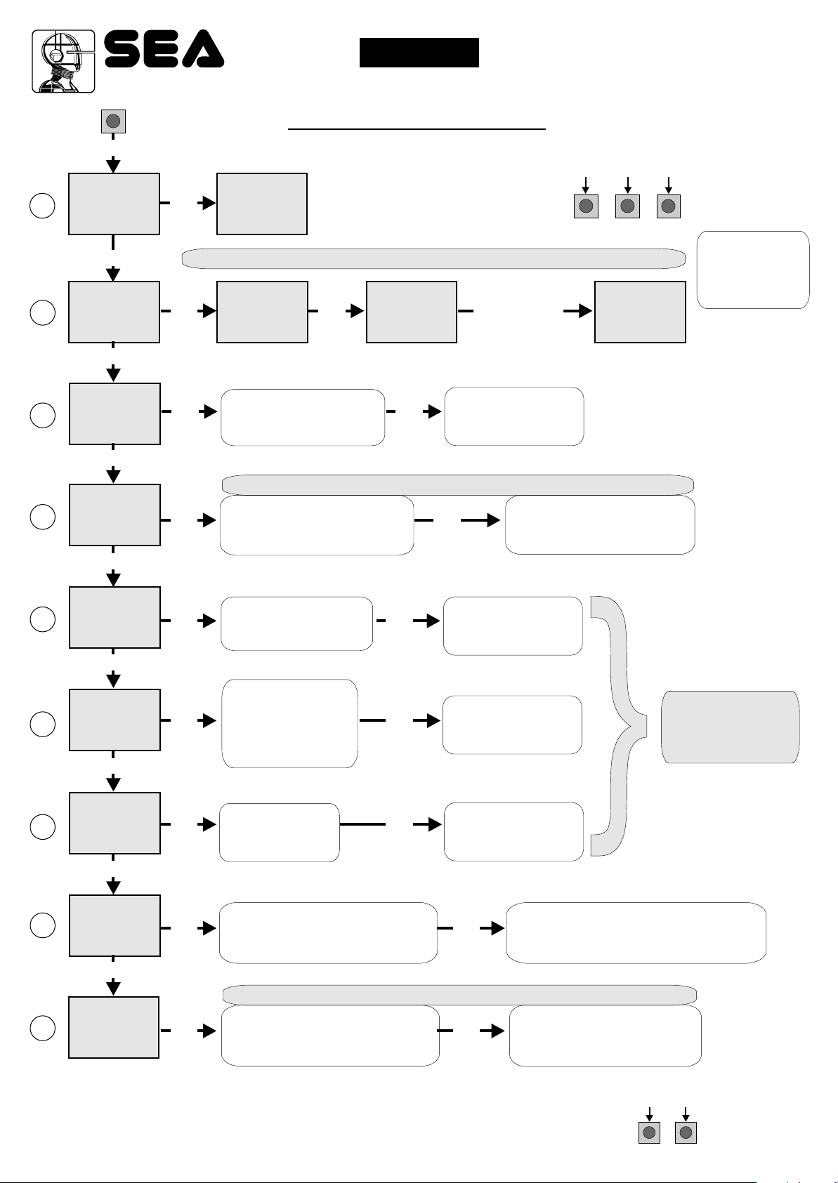
QUICK START
MENU
1
LANGUAGE
MENU
2
TRANSMITTERS
MENU
3
MENU
ONE SINGLE
4
UP
SEA
UP
SEA
UP
SEA
MOTOR
UP
SEA
LEAF
UP
SET
OK
SEA
MENU
ITALIANO
SET
Skip this step if you do not want to program a transmitter
SET
OK
SET
OK
SEA
MENU
SET
START
Choose the type of
motor with
UP or DOWN
MENU
OK
Skip this step if you are working in double leaf mode
SET
OK OK
With UP or DOWN choose
ON only if in single
leaf mode
SEA
PRESS
BUTTON
OK
SET
Press the
button of the
TX to be
stored
To confirm and return
to main menu
To confirm and return
to the main menu
PROGRAMMING
BUTTONS
DOWNUP
MENU
STORED
SEA
OK
SET
OK to exit Menu
or press the
button of the next
TX to be stored
MENU
5
MENU
6
PAUSE TIME
MENU
7
MENU
PROGRAM-
8
MENU
9
TEST START
SEA
LOGIC
UP
SEA
UP
SEA
START IN
PAUSE
UP
SEA
MING
UP
SEA
SET
OK OK
With UP or DOWN
choose
the desired logic
SET
OK OK
With UP or DOWN
choose a delay for
automatic closing
SET
OK OK
With UP or DOWN
Choose ON
SET
OK OK
With UP or DOWN choose ON
to start times learning
Skip this step if a TX has already been stored
SET
OK OK
UP or DOWN Choose
With
ON to start test
To confirm and return
to main menu
To confirm and return
to main menu
To confirm and return
to main menu
At the end of the selflearning
the control unit returns automatically
To confirm and return to
main menu
Skip this step
if you wna tto work
in half-automatic
logic
to the main menu
ALL OTHER PARAMETERS HAVE DEFAULT SETTINGS WHICH ARE USEFUL FOR THE 90% OF THE
APPLICATIONS BUT CAN BE HOWEVER SET THROUGH THE SPECIAL MENU. FOR ENTERING INTO THE
SPECIAL MENU PRESS THE UP AND DOWN BUTTONS AT THE SAME TIME FOR 5 S.
67411655
REV 01 - 11/2013
UPDOWN
27
Sistemi Elettronici
di Apertura Porte e Cancelli
International registered trademark n. 804888
®
English
USER 2 - 24V DG
“ALL IN”
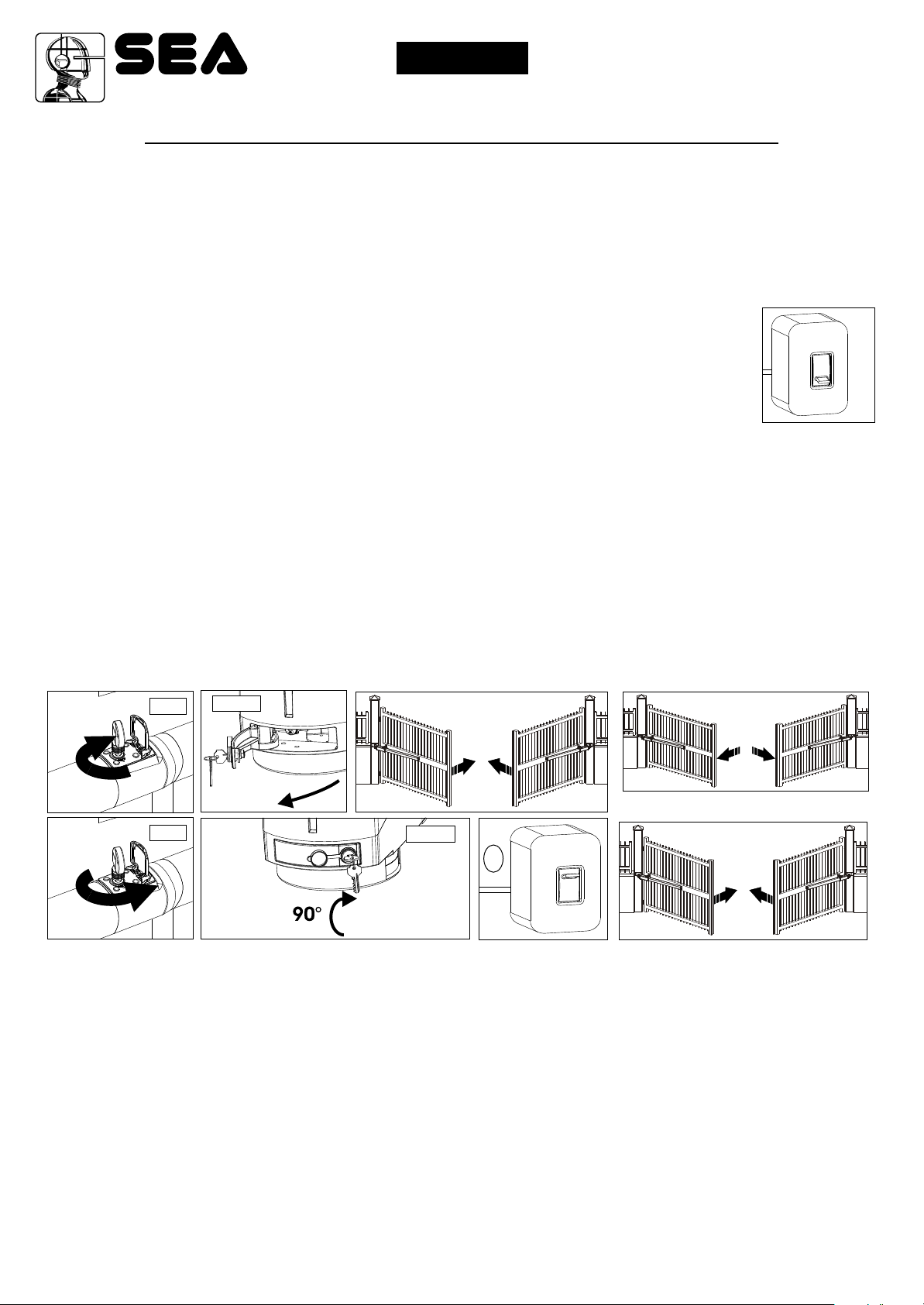
WORKING TIMES SELF LEARNING
The control unit is pre-set with the default settings, to start the control unit with the
DEFAULT settings just keep pressed the UP and DOWN buttons at the same time power
supplying the control unit the display shows the message init.
The DEFAULT settings are shown in the Menues table.
Note1: Put a jumper on SAFETY EDGE contact if not used.
Fig. 1
Note2: It is not necessary to put a jumper on the limit switches, photocells and Stop if they
are not used.
F
F
O
1) Check the right operation of the accessories (photocells, buttons etc.).
If necessary set the leaf delay.
2) If necessary adjust the selflearning speed.
3) Switch off power supply (Fig. 1), release the motors (Fig. 2-3) and manually place the leaf on
the middle of the stroke (Fig. 4).
Restore the mechanical lock (Fig. 5-6)
4) Power the control unit (Fig.7)
5) Choose the desired motor type; use (default Flipper).
UU
6) Select 8-progRA ING on the display, press OK and then UP and DOWN to start the programming.
Note3: If on single leaf mode set 4-ONE SINGLE LEAF on ON.
Note4: If one or both motors start in opening, switch off power and invert the motor(s) cable starting in opening.
U
Afterwards repeat the procedure starting from point 4, or activate 19-REUERSE OTOR.
7) Both leaves will start a CLOSE - OPEN - CLOSE cycle automatically (CLOSE M2 - CLOSE M1 - OPEN M1 OPEN M2 - CLOSE M2 - CLOSE M1).
End of selflearning.
Fig. 4
Fig. 8
Release
BETA
FLIPPER
Fig. 2
Lock
Fig. 5
BETA
Operator
released
Operator
locked
Fig. 3
M1
FLIPPER
Fig. 6
A
Fig. 7
M2M1
M2
Fig. 9
N
O
M1
M2
28
67411655
REV 01 - 11/2013
Sistemi Elettronici
di Apertura Porte e Cancelli
International registered trademark n. 804888
®
English
USER 2 - 24V DG
“ALL IN”
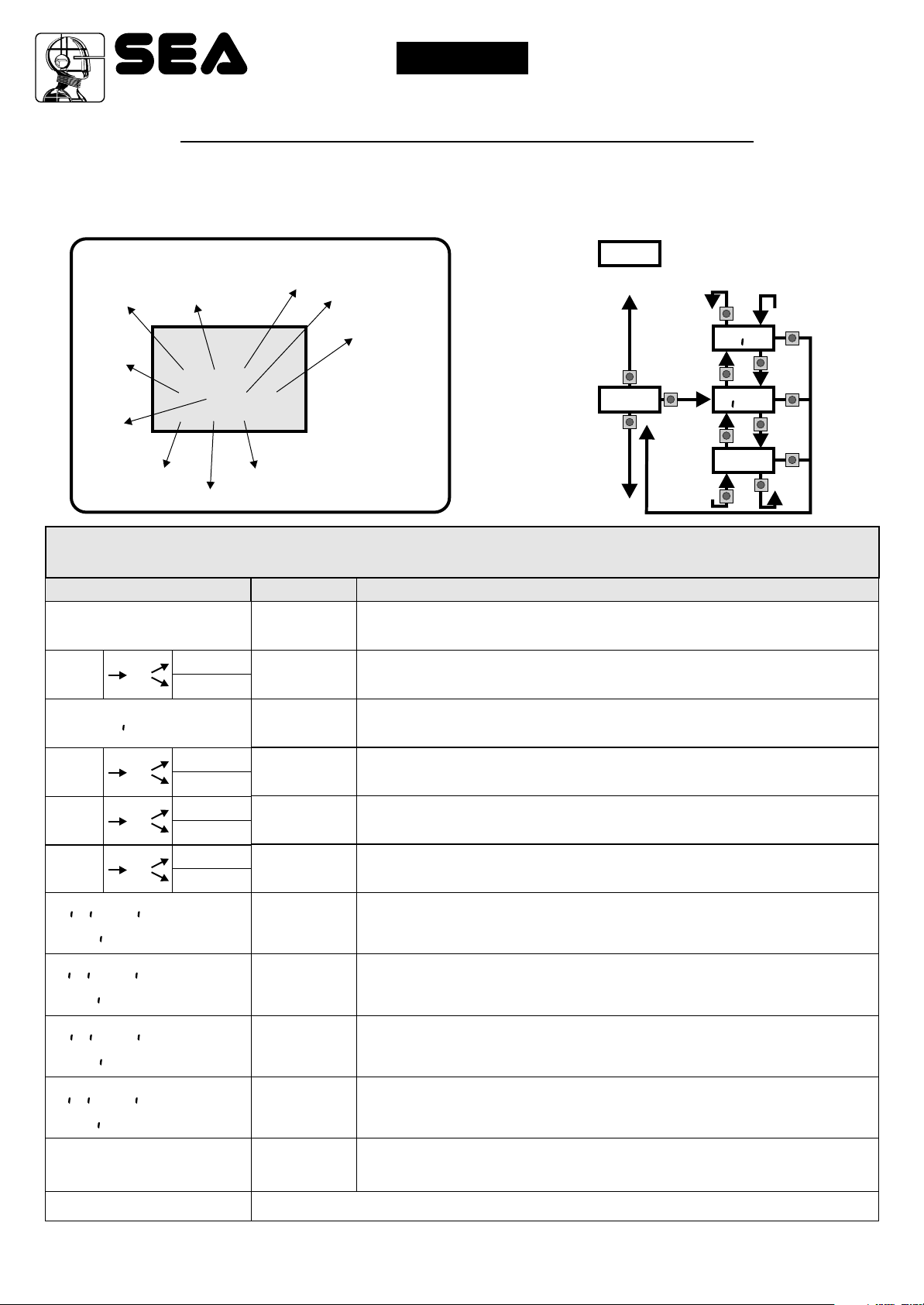
SELECTION OF THE SETTINGS
The settings of the control unit are made through the UP, DOWN and OK buttons. The UP and DOWN buttons to scroll through the MENUS and
SUBMENUS. By pressing OK you enter from MENU into SUBMENU and confirm the choice.
Moving in the language menu pressing the UP and DOWN buttons at the same time you access the SP MENU for special settings.
Moving in the language menu pressing the OK button for 5 seconds, you enter the CHECK MENU, where you can check the operating status of
all inputs.
Limit
Switch
opening
motor 1
Start
Limit
Switch
closing
motor 1
DISPLAY INPUT STATUS
Start
pedestrian
MENU
SEA
---
----
---
Photocell 1
Photocell 2
Edge
SET
Stop
Limit Switch
opening motor 2
Limit Switch
closing motor 2
When the segment
is ON during selflearning, the input
status is closed or
OFF.
Initial system
u.001
Programming example
UP
U
otor
DOWN
Software Version
UP
FL PP
UP
OK
F ELD
UP
SVRF
UP
OK
DOWN
OK
DOWN
OK
DOWN
MENU FUNCTION TABLE CHECK USER 2 24V DG “ALL IN” INPUTS
To access the Menu for input check keep pressed OK for about 5 seconds.
MENU
start
stop
OK
PedESTR AN Start
EDGE
PHOTO1
PHOTO2
OK
OK
OK
U
L T SU T(H
OPEN NG 1
U
L T SU T(H
(LOS NG 1
U
L T SU T(H
OPEN NG 2
U
L T SU T(H
(LOS NG 2
enabled
blo(ked
enabled
blo(ked
enabled
blo(ked
enabled
blo(ked
Description
Start test
Stop test
Pedestrian
start test
Safety
edge test
Photocell 1
test
Photocell 2
test
M1 opening
limit switch
test
M1 closing
limit switch
test
M2 opening
limit switch
test
M2 closing
limit switch
test
Description
The contact must be a N.O. Contact . When activating the related command
on the display SET lights up, the input works.
If SET is always on, check the wirings.
The contact must be a N.C. Contact. If activating the related command on
the display SET lights up, the input works.
If SET is always on, make sure that the contact is a N.C. Contact.
The contact must be a N.C. Contact. If activating the related command on
the display SET lights up, the input works.
If SET is always on, make sure that the contact is a N.C. Contact.
The contact must be a N.C. Contact. If activating the related command on
the display SET lights up, the input works.
If SET is always on, make sure that the contact is a N.C. Contact.
The contact must be a N.C. Contact. If activating the related command on
the display SET lights up, the input works. If SET is always on, make
sure that the contact is a N.C. contact or that the related limit switch is not occupied.
The contact must be a N.C. Contact. If activating the related command on
the display SET lights up, the input works. If SET is always on, make
sure that the contact is a N.C. contact or that the related limit switch is not occupied.
The contact must be a N.C. Contact. If activating the related command on
the display SET lights up, the input works. If SET is always on, make
sure that the contact is a N.C. contact or that the related limit switch is not occupied.
The contact must be a N.C. Contact. If activating the related command on
the display SET lights up, the input works. If SET is always on, make
sure that the contact is a N.C. contact or that the related limit switch is not occupied.
0.0u
Batteries’
voltage level
END
Note: If the Stop, Photocell 1 and Photocell 2 contacts are not bridged in self-learning, they will be deactivated and can be
reactivated through this menu, without repeating times self-learning.
67411655
REV 01 - 11/2013
Batteries charge level indicator
Exit menu
29
Sistemi Elettronici
di Apertura Porte e Cancelli
International registered trademark n. 804888
®
USER 2 - 24V DG
English
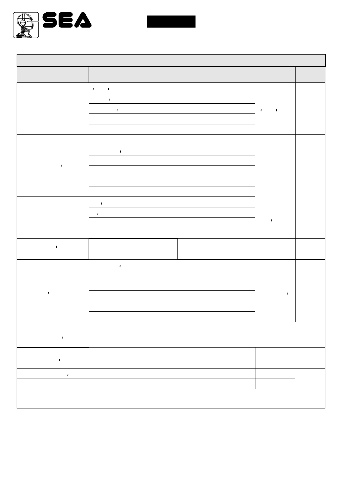
MENU FUNCTIONS TABLE USER 2 24V DG “ALL IN”
“ALL IN”
MENU
1 - langvage
U
2 - trans tters
U
3 - otor
SET
tal ano
engl sk
fran(a s
espanol
dut(k
start
Pedestr an Start
U
External odvle
stop
U
Delete a trans itter
UU
(Lear e ory
FL PPER - ger
F ELD
SVRF-ALP
BETA
Description
Italian
English
French
Spanish
Dutch
Start
Pedestrian Start
External module
Stop
Delete single transmitter
Delete transmitter memory
Flipper - Ger motors
Field motors
Surf - Alpha motors
Beta motors
Default
tal ano
start
Ped Start.
FL PPER
Set value
4 - one s ngle
leaf
5 - log (
U
6 - paVse t e
7 - starT n pavse
U U
8 - progra ng
9 - test start
end
On off
U
Avto at (
open-stop-(lose-stop-open
open-stop-(lose-open
2 bvttons
safety
U
Dead an
off
1,2,3
off
on
Off on
Off on
Select END and press OK to exit the menu.The menu
deactivates automatically after 2 minutes
In ON activates single
leaf mode
Automatic
Step by step type 1
Step by step type 2
Two buttons
Safety
Dead man
OFF
(semi-automatic logics)
Setting from 1s to 4min.
In pause start is not acceped
In pause start is accepted
Times learning start
Start command
off
U
Avto at (
off
off
off
off
30
67411655
REV 01 - 11/2013

®
English
Sistemi Elettronici
di Apertura Porte e Cancelli
International registered trademark n. 804888
PRESS AT THE SAME TIME FOR 5 SECONDS TO ENTER OR TO EXIT THE SPECIAL MENU
UPDOWN
USER 2 - 24V DG
“ALL IN”
SPECIAL MENU FUNCTIONS TABLE USER 2 24V DG
“ALL IN”
To ENTER the Special Menu keep pressed UP and DOWN at the same time for 5 seconds.
To EXIT the Special Menu pressed END or keep pressed UP and DOWN at the same time for 5 seconds.
MENU SP
U
1 - OTOR SPEED 1 *
U
2 - OTOR SpEED 2 *
3 - sloudoun speed *
4 - learn ng speed *
5 - leaf delay n open ng
6 - leaf delay n (los ng
30 100
30 100
30 100
30 100
Off 6
Off 20
SET
Description
Setting from 30 to 100
Setting from 30 to 100
Setting from 30 to 100
Setting from 30 to 100
Setting from OFF to
6 seconds
Setting from OFF to
20 seconds
Default
75
75
30
50
3
3
Set Value
Opening torque M1 and
amperometric sensitivity
7 - open ng torq 1 *
10 100
Note: By increasing the
70
torque the sensitivity
decreases
Closing torque M1 and
amperometric sensitivity
8 - (los ng torq 1 *
10 100
Note: By increasing the
70
torque the sensitivity
decreases
Opening torque M2 and
amperometric sensitivity
9 - open ng torq 2 *
10 100
Note: By increasing the
70
torque the sensitivity
decreases
Closing torque M2 and
amperometric sensitivity
10 - (los ng torq 2 *
10 100
Note: By increasing the
70
torque the sensitivity
decreases
11 - Pvshouer
12 - pvsk ng stroke
13 - open ng sloudoun 1
14 - (los ng sloudoun 1
67411655
Off
Open ng and (los ng
Only open ng
Only (los ng
Off 3
Off
5 100
Off
5 100
REV 01 - 11/2013
Disabled
Opening an closing
Opening only
Closing only
From OFF to 3 seconds
Disabled
Setting from 5 to 100
Disabled
Setting from 5 to 100
Off
Off
30
30
31

Sistemi Elettronici
di Apertura Porte e Cancelli
International registered trademark n. 804888
®
English
USER 2 - 24V DG
“ALL IN”
MENU SP
15 - open ng sloudoun 2
16 - (los ng sloudoun 2
17 - preflasx ng
18 - flasx ng l gxt
U
19 - reuerse otor
20 - en(oder
SET
Off
5 100
Off
5 100
Only (los ng
0.0 5.0
U
Nor al
L gxt
aluays
bvzzer
Off
On
On Off
N (y(le
Description
Disabled
Setting from 5 to 100
Disabled
Setting from 5 to 100
Pre-flashing active only
before closing
Pre-flashing time
Normal
Control lamp
Always ON
Buzzer
Synchronized right motor
Synchronized left motor
In ON enables the
Encoder, in OFF
it's disabled
Courtesy light in cycle
Default
30
30
Off
U
Nor al
Off
Off
Set Value
21 - (ourtesy l gxt
22 - traff ( l gxt
reseruat on
23 - pedestr an open ng
24 - pedestr an PAUSE
25 - a((elerat on
U
26 - a ntenan(e (y(les
U
27 - perfor ed (y(les
U
28 - t er
Off
1 240
Off on
20 100
= start
Off
1 240
0 100
100 10e4
0 10e4
off
ON PXOTO2
ON PEDESTR AN ENTRY
Disabled
Courtesy light setting
from 1s to 4min.
When setting this function
the pedestrian input will be
activated to work on the
auxiliary board SEM
(traffic light management).
Setting from 20 to 100
Pause in pedestrian
opening same as in
total opening
Disabled
Setting from 1s to 4 min.
Acceleration ramp
Setting from 100 to
100000
Reports the executed
cycles. Keep pressed OK
to reset the cycles
Disabled
Timer function active
on photocell 2
Timer function active on
pedestrian input
N (y(le
Off
100
= start
75
10e4
0
off
32
67411655
REV 01 - 11/2013

Sistemi Elettronici
di Apertura Porte e Cancelli
International registered trademark n. 804888
®
English
USER 2 - 24V DG
“ALL IN”
MENU SP
29 - edge
30 - PXOTO1
31 - PXOTO2
SET
U
Nor al
8x2
(LOS NG
OPEN NG
stop
Stop AND (LOSE
(LOSE
PAUSE RELOAD
Delay pause ti e
(LOS NG
OPEN NG
stop
Stop AND (LOSE
(LOSE
PAUSE RELOAD
Delay pause ti e
Description
Normal N.C. contact
Edge is active and
Default
Nor al
Set Value
U
protected by a 8k2 resistor
Photocell active in
closing
Photocell active in
opening
Photocell active before
opening
The photocell stops in closing
and closes when released
The photocell gives a
command to close during
opening, pause and
(LOS NG
closing
The photocell charging the
pausing time
If the photocell is occupied
during opening, pause or
u
closing, the gate reopens
completely and closes
without observing the
pause time.
Photocell active in
closing
Photocell active in
opening
Photocell active before
opening
The photocell stops in closing
and closes when released
The photocell gives a
command to close during
opening, pause and
OPEN NG
closing
The photocell charging the
pausing time
If the photocell is occupied
during opening, pause or
u
closing, the gate reopens
completely and closes
without observing the
pause time.
67411655
REV 01 - 11/2013
33

Sistemi Elettronici
di Apertura Porte e Cancelli
International registered trademark n. 804888
®
English
USER 2 - 24V DG
“ALL IN”
MENU SP
32 - 24u avx
33 - POS T ON RE(OUERY
U
34 - OTOR RELEASE *
35 - PER OD (AL pvshouer
36 - ant ntrvs on
U
37 - LOCK T E
Description
Default
ALUAYS
ALUAYS
N (Y(LE
OPEN NG
(LOS NG
N pavsE
SET
24Vaux output always
power supplied
24V output active only
during cycle
24Vaux output power
supplied only during opening
24Vaux output power
supplied only during closing
24Vaux output power
supplied only during pause
24Vaux output for
fototest
connection of photocell
TX to autotest
N (Y(lE AND fototest
0 15
Off
1 100
24V output only during cycle
with fototest function active
Regulates the recovery of
the motor inertia
Disabled
Setting from 1 to 100
Allows the repetition of the
Pushover functionat a
off 8 off
distance of time adjustable
from 0 to 8 hours at hourly
intervals
ONLY OPEN NG
ONLY (LOS NG
OPEN NG AND (LOS NG
Off
Off 5
Only on limit switch in opening
Only on limit switch in closing
On limit switches in closing
and in opening
Disabled
Sets the lock release
time from 0 to 5 s
Set Value
6
off
Off
1
38 - lock
39 - FLASX NG L GXT AND
U
t er
40 - d agnost (S
41 - fototest
34
67411655
ONLY OPEN NG
ONLY (LOS NG
OPEN NG AND (LOS NG
Off
On
1 10
PXOTO1
PXOTO2
PXOTO1-2
REV 01 - 11/2013
Active only before opening
Active only before closing
Active before opening
and closing
The flashing light remains
OFF with the active timer
and open gate
The flashing light remains
ON with active timer and
open gate
Shows last event
(See alarms table)
Auto-test active only on
Photo1
Auto-test active only on
Photo2
Auto-test active on
Photo1 and Photo2
OPEN NG
off
Foto1-2

Sistemi Elettronici
di Apertura Porte e Cancelli
International registered trademark n. 804888
®
English
USER 2 - 24V DG
“ALL IN”
MENU SP
42 -OPEN NG TOLERAN(E
U
otor 1
43 - (LOS NG TOLERAN(E
U
otor 1
44 -OPEN NG TOLERAN(E
U
otor 2
45 - (LOS NG TOLERAN(E
U
otor 2
46 - OPEN NG SENS T U TY
U
otor 1 *
47 - (LOS NG SENS T U TY
U
otor 1 *
48 - OPEN NG SENS T U TY
U
otor 2 *
49 - (LOS NG SENS T U TY
U
otor 2 *
U
50 - sELE(T L T SU T(K
51 - passuord
END
SET
Description
Default
Adjust the amperometric
0 100
tolerance in relation to the
detected stop in opening
Adjusts the amperometric
0 100
tolerance in relation to the
detected stop in closing
Adjust the amperometric
0 100
tolerance in relation to the
detected stop in opening
Adjusts the amperometric
0 100
tolerance in relation to the
detected stop in closing
Adjusts the revesing
10 99
sensitivity on motor 1 in
opening. Note: Only with
Encoder On active.
Off
Disabled
Adjusts the revesing
10 99
sensitivity on motor 1 in
closing. Note: Only with
Encoder On active.
Off
Disabled
Adjusts the revesing
10 99
sensitivity on motor 2 in
opening. Note: Only with
Encoder On active.
Off
Disabled
Adjusts the revesing
sensitivity on motor 2 in
10 99
closing. Note: Only with
Encoder On active.
Off
U
Avto at (
Disabled
Limit switch in automatic
recognition
Only limit switch in
ONLY OPEN NG
ONLY (LOS NG
opening present
Only limit switch in
closing present
Avto at (
Allows the entering of a
password which blocs the
---- ----
modification of the control unit
parameters (see page 37)
Select END and press OK to exit the special menu.
The special menu deactivates automatically after 20 minutes.
Set Value
0
0
0
0
off
off
off
off
U
Note 1: The * indicates that the default value may change depending on the selected motor type.
Note 2: After initialization the parameters "motor type" and "limit switch type" remain son the value chosen in
the setup program.
67411655
REV 01 - 11/2013
35

®
Sistemi Elettronici
Sistemi Elettronici
di Apertura Porte e Cancelli
di Apertura Porte e Cancelli
International registered trademark n. 804888
International registered trademark n. 804888
®
English
USER 2 - 24V DG
“ALL IN”
RADIO TRANSMITTER SELF LEARNING
WITH RECEIVER ON BOARD OF CONTROL UNIT
!!
WARNING: Make the radio transmitters programming before you connect the antenna and insert the receiver into the special
CMR connector (if available) with turned off control unit. (The control unit automatically recognizes if the receiver is a RF, RF Roll, RF
Roll Plus or RF UNI module).
With RF Roll or RF Roll Plus module it will be possible to use only Coccinella Roll or Coccinella Roll Plus radio transmitters. or Smart
Dual Roll or Smart Dual Roll Plus.
With the RF UNI module it will be possible to use both the transmitters of the Roll Plus series and those with fixed code. The first
memorized transmitter determines the type of the remaining radio transmitters.
Select through the display trans itters and press OK, now select with the UP and DOWN buttons, the command to which you want to
associate the button (it is possible to associate max. 2 commands) and press OK to confirm the choice, now press the button of the radio
transmitter which you want to associate. If the storage is successful, the display will show STORED .
If the receiver is a Rolling Code, press twice the button of the radio transmitter that you want to program to memorize the first TX.
In the trans itters MENU it is possible to select Start (to associate a Start command), pedestrian start (Pedestrian Start ), external
U
odvle (For the activation of a contact on the EXP output), StoP (To associate the STOP command to the TX), dELete a trans itter (To
U
delet the single transmitter only if it is a Rolling Code Plus), (lear e ory (To delete all TX).
Notes:
- Enter radio transmitters learning only when the working cycle stops and the gate is closed.
- If the radio transmitters are Rolling Code it’s possible to memorize up to 800 codes (buttons).
- If the radio transmitters are with fixed code it will be possible to memorize up to max. 30 codes (buttons).
- You can store max. 2 of the available 4 functions. If the control unit receives a code which was already associated to another function it will be
updated with the new function.
U
U
U
U
DELETE TRANSMITTERS FROM THE RECEIVER
With modules different from RF UNI, it will be possible to delete only the entire memory of the receiver.
Proceed as follows: select from the menu trans itters: (lear e ory and hold the OK button until the display shows the message Ok.
U
U U
With the RF UNI module, it will be possible to also delete the single button of the transmitter.
It can be done in two ways:
1) If you have the transmitter, or if you are using transmitters with fixed code, the cancellation can be executed by simply retransmitting the code.
Ex. Button 1 of the transmitter memorized as START; access the menu trans itters press OK, select STaRT, press OK.
U
Send a STaRT command from the transmitter and on the display will show deleted.
At this point the single button results deleted.
2) If you do not have a transmitter, or you are using a Roll Plus transmitter, you can delete the transmitter selecting the serial number of the
transmitter to be deleted.
Procede as follows: Access the menu trans itters, press OK, select Delete a trans itter, press OK, choose the memory location to be
UU
deleted through the UP and DOWN buttons, press OK, check on the display if the serial number of the transmitter to be deleted is the right one,
press OK, on the display shows SvRE?, if the transmitter to be deleted is the right one press OK and OK will appear to confirm the cancellation,
otherwise press the DOWN button to return to the menu trans itters.
U
Note: When using Roll Plus transmitters, it is recommended to record on a table similar to the below example, the serial number associateding
it to the memory location where it was stored.
Transmitter
button
0
1
2
3
4
5
6
7
8
9
10
11
12
13
14
15
16
17
18
19
20
1 2 3 4
REV 01 - 11/2013
Serial number Customer
36
TABLE
EXAMPLE
67411655
Memory
location

Sistemi Elettronici
di Apertura Porte e Cancelli
International registered trademark n. 804888
®
English
USER 2 - 24V DG
“ALL IN”
FUNCTION LOGIC
AUTOMATIC LOGIC
A start impulse opens the gate. A second impluse during the opening will not be accepted.
A start impulse during closing reverses the movement.
NOTE 1: To have the automatic closing it is necessary to set a pause time, otherwise all the logic will be semi-automatic.
NOTE2: It is possible to choose, whether to accept or not, the start in pause, selecting in the MENU the item Startin
pavse and choosing ON or OFF. By default, the parameter is OFF.
SECURITY LOGIC
A start impulse opens the gate. A second impulse during opening reverses the movement.
A start impulse during closing reverses the movement.
NOTE 1: To have the automatic closing it is necessary to set a pause time, otherwise all the logic will be semi-automatic.
NOTE2: It is possible to choose, whether to accept or not, the start in pause, selecting in the MENU the item Startin
pavse and choosing ON or OFF. By default, the parameter is OFF.
STEP BY STEP TYPE 1 LOGIC
The start impulse follows the OPEN-STOP-CLOSE-STOP-OPEN logic.
NOTE 1: To have the automatic closing it is necessary to set a pause time, otherwise all the logic will be semi-automatic.
NOTE2: It is possible to choose, whether to accept or not, the start in pause, selecting in the MENU the item Startin
pavse and choosing ON or OFF. By default, the parameter is OFF.
STEP BY STEP TYPE 2 LOGIC
The start impulse follows the OPEN-STOP-CLOSE -OPEN logic.
NOTE 1: To have the automatic closing it is necessary to set a pause time, otherwise all the logic will be semi-automatic.
NOTE2: It is possible to choose, whether to accept or not, the start in pause, selecting in the MENU the item Startin
pavse and choosing ON or OFF. By default, the parameter is OFF.
DEAD MAN LOGIC
The gate opens as long as the START button of opening is pressed; releasing it the gate stops. The gate closes as long as the
button connected to the PEDESTRIAN START is pressed; releasing it the gate stops. To execute complete opening and/or
closing cycles the related pushbuttons must be constantly pressed.
2 PUSHBUTTONS LOGIC
One start opens, one pedestrian start closes. In opening the closing will not be accepted. In closing a start command reopens, a
pedestrian start command (closes) will be ignored.
PASSWORD ENTERING MANAGEMENT
With a new control unit all menus can be displayed and set and the password will be disabled.
Selecting one of the Menus and keeping UP and DOWN pressed at the same time for 5 seconds, you will access the SP Menu
containing the Passuord Submenu.
Pressing OK in the Passuord Menu, you will proceed with the entering of the numeric code of the 4-digit PASSWORD.
Use UP and DOWN to increase or decrease the number, press OK to confirm it and you will pass automatically to the entering of
the next number. Pressing OK after the last entered number the word SvRE? appears, confirm the activation of the PASSWORD
and the message Ok appears, pressing UP or DOWN instead you can cancel the operation and NO OPERATION will appear on the
display.
Once entered the PASSWORD, it will be definitively activated, once the display switch off timeout has expired, or by turning off
and on again the control unit. Once the PASSWORD has been activated, the menus of the display can be only displayed but not
set. To unlock them you must enter the correct PASSWORD in the Passuord menu, if the password is wrong the message ERRor
will appear.
At this point, if the password has been entered correctly, the menus will be unlocked and it will be possible to change the
parameters of the control unit again.
If the control unit has been unlocked through Passuord Menu, it is possible to enter a new and different password, using the
same entering process as for the first one; at this point, the old password will no longer be valid.
If the password has been forgotten, the only way to unlock the control unit is to contact the SEA technical assistance, which will
assess whether to provide the procedure to unlock the control unit or not.
Note: The password cannot be set through the Jolly or Jolly 2 terminal.
67411655
REV 01 - 11/2013
37

Sistemi Elettronici
di Apertura Porte e Cancelli
International registered trademark n. 804888
®
English
USER 2 - 24V DG
“ALL IN”
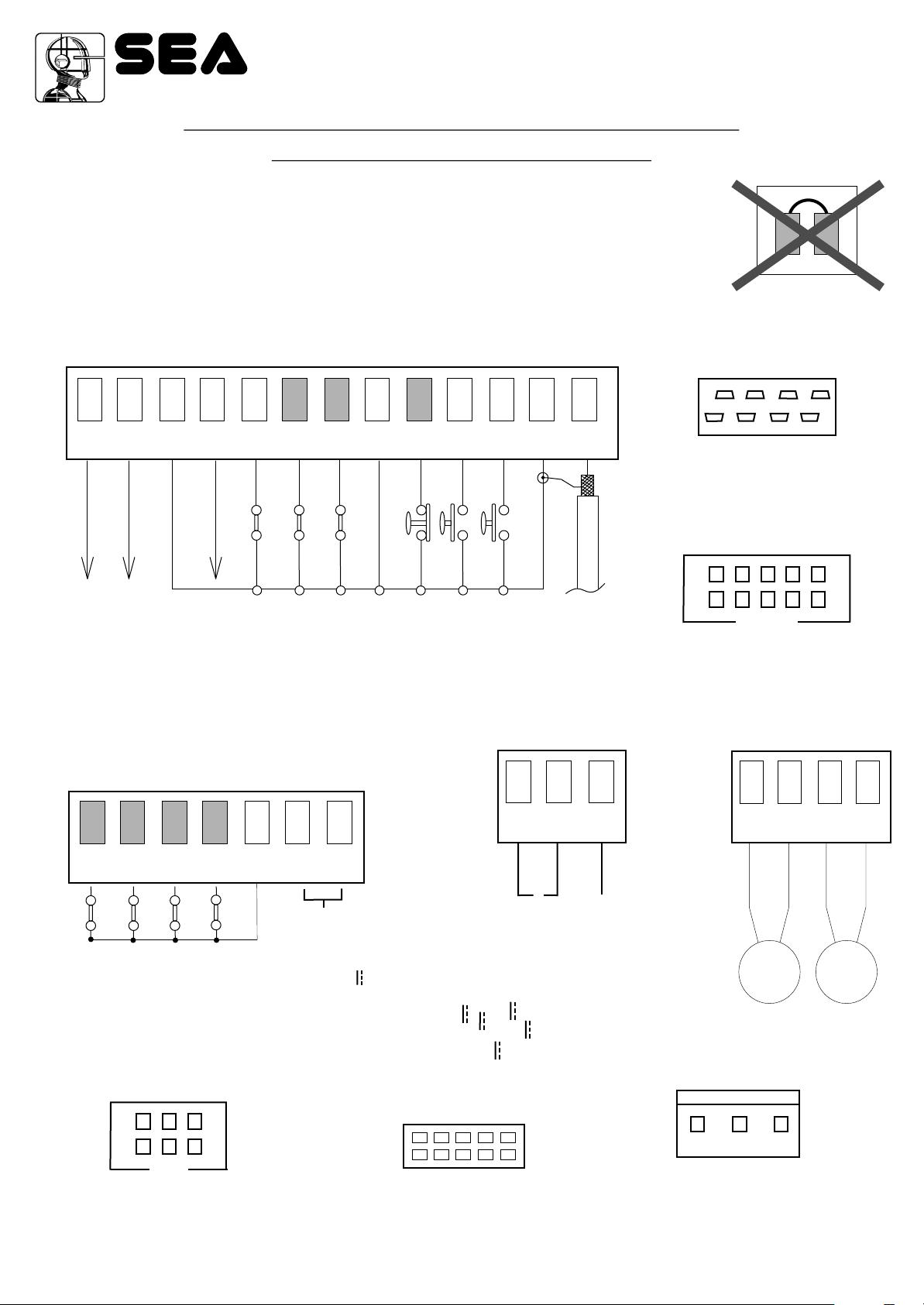
START - STOP - PEDESTRIAN START - ANTENNA PHOTOCELL
Photocell 2
8
TX2
Photocell 1
7
11
12
678
Common
6
TX1
6
6
CN1
5
Stop
5
11
12
4
RX2
Photocell 1 and Photocell 2 Connections
+ = 24VL COM = 0V PH1 = Photocell contact 1 PH2 = Photocell contact 2
Note1: For the autotest connect in the menu 32-24uavk the TX to the 24VAux clamp and activate
the Autotest function. Note2: The in (y(le and fototest function will keep the photocells
OFF while the gate is closed, thus saving energy. Note3: On the 41-fototest menu you can
3
Start ped.
12
Common
Start
2
3
4
RX1
11
12
11
12
also activate the self-test even on the single photocell. The standard setting of the photocell 1 is
FOTO CLOSE and the one of the photocell 2 is FOTO OPEN. The photocell 2 can be set also as
TIMER (see TIMER function). The selftest can be applied also on single photocell.
Antenna
OPTIONS ON FOTO1 and FOTO2 adjustable on on- board display or with JOLLY terminal.
FOTO CLOSE activation ((losing): if occupied, reverses the movement in closing, during pause it
prevent the closing.
Activation repeat pause (pavse RELOAD): If occupied, during pause it recharges the timer of pause. In
closing it reverses the movement.
FOTO OPEN activation (oPEning): If activated the photocell blocks the movement as long as it’s busy,
when released the opening continues.
FOTO PARK activation (stop and (lose) : in opening it is not active; in pause are activated it
commands the closing when released, otherwise it’s not active; in closing it stops the movement as long
as it is busy, when released the closing continues.
1
FOTO STOP activation (STOP): When activated before the opening the photocell blocks the automation
as long as it is busy, during the opening it will be ignored. In closing the intervention of the photocell
causes the reopening.
Activation PHOTO CLOSE IMMEDIATELY ((lose): The photocell stops the gate as long as it is
occupied in both opening and closing, when released it gives a closing command (Closing one
CN1
11 12
Common
second after release of the photocell ).
delay pause ti e activation: If the photocell is occupied during opening, pause or closing, the
gate reopens completely and closes without observing the pause time.
24VL accessories
STOP (N.C.) The STOP is connected between the clamps 2 and 5 of the CN1
terminal . The pressure on this button immediately stops the motor in any
condition/position. A start command is needed to re-start the movement.
After a stop the motor always re-starts in closing.
u
Options 24Aux can be set with on-board Display or with Jolly device.
It is possible to chose when having tension on the 24Aux output. The options are:
always, only during opening, only during cycle, only before opening or only during
pause. When using control units with batteries and / or solar panels, we
recommend connecting the accessories which are not used when operator
stands still (e.g. photocells) to a 24VAux output, setting the option “in (y(le”.
With this setting you can save energy by lowering power consumption in stand-by,
increasing the autonomy of the system.
PEDESTRIAN START (N.O.) The pedestrian start can be connected between
the clamps 2 and 4 of the CN1 terminal .
This input allows a partial opening the opening space can be set through the onboard display or through the JOLLY device.
Note1: The contact for partial opening is a N.O. Contact (Normally open).
Note2:In 2 BUTTONS logic it is necessary to keep pressed the Start Ped. to re-
close the automation.
Note3: In dead man logic this button executes the re-closing if you keep it
pressed.
Note4: When closed during pause, the gate will reclose only after this input has
been reopened.
TIMER activation: This input can be transformed into TIMER (See TIMER).
START (N.O.) The
An impulse given to this contact opens and closes the automation depending onthe selected logic it can be given by a key switch, a keypad,
etc. To connect the other devices refer to the related instructions leaflets. (ie. loop detectors and proximity switches).
Note1: In DEAD MAN logic it is necessary to keep pressed the Start for the opening of the automation.
Note2:
In 2 BUTTONS logic this button performs the opening.
Timer activation: it is possible to connect a timer on the start only in auto logic with time of pause different than DISB and with START IN
PAUSE function OFF.
TIMER
38
Can be activated through on-board display or through the Jolly programmer. In both cases it’s a N.O. contact which provoques the opening of the
automation keeping it open until it is activated. When it’s released, the gate attends the set pausing time and executes the reclosing. The TIMER
command can be activated on the inputs FOTO2, START PEDESTRIAN.
Note1: When activated on the pedestrian entry, the pedestrian will be disabled also on the radio transmitter.
Note2: In case of intervention of a security device during the timer (Stop, Ammeter, Edge), to restore the movement it will be necessary to give a
start impulse.
Note3: In case of no power supply with open gate and active Timer the control unit will restore its use, otherwise if during restore of the power
supply the TIMER is not activated it will be necessary to give a start impulse for the reclosing.
67411655
START is connected between the clamps 2 and 3 of the CN 1 terminal.
REV 01 - 11/2013

Sistemi Elettronici
di Apertura Porte e Cancelli
International registered trademark n. 804888
®
English
USER 2 - 24V DG
“ALL IN”
AMPEROMETRIC MANAGEMENT
AMPEROMETRIC DEVICE FOR ELECTROMECHANICAL OPERATORS
This control unit comes with an obstacle detection system working only on electromechanical operators
allowing to have the reversing on obstacles and the automatic detection of the stops.
The sensitivity is adjustable for single leaf and single opening and closing direction through the torque
parameter.
ATTENTION: The first operation after power failure, will be executed with the set speed to search the
mechanical stops limit.
ELECTRO- LOCK AND WARNING LAMP - EDGE
CN2
14 15 16 17 18 19 20
13
FL(-)
10
1112
Common
24VL
CN1
789
Electro-lock exit
An electro-lock of 12V 15VA max can be connected. It is
possible to disactivate the electroc-lock if not used. This
operation allows to save energy of the control unit. The
release of the electro-lock can be timed’ from 0 to 5 s.
20
19
ELECTRO- LOCK
5
6
3
4
12
9
11
Flashing Lamp 24VL 15W (Warning lamp ) /
24VL 4W Led
The warning lamp advises that the automatic gate is in
movement performing 1 flash /second in opening and 2
flashes / second in closing. Instead it remains turned on fix
during pause.
To connect it, connect the wires of the warning lamp as
shown in the figure. Note: It is recommended to use the
flash 24V Led.
Pre-flashing form 0 to 5 seconds can be activated before
operator start or only before closing.
Furthermore from the flashing lamp it is possible to verify
some alarm signals. See alarms indications.
It is possible to set this exit with fixed flashing also when the
gate is not moving or it is possible to change this exit into
control lamp. In such case all the indications of alarm
remain on the warning lamp as long as they are active.
12
13
67411655
WARNING LAMP
Safety edge
REV 01 - 11/2013
SAFETY EDGE
It is possible to connect an active safety edge on the
terminal CN1. If this device is pressed it opens the contact
causing a partial inversion of the movement both in opening
and in closing. If not used bridge the contacts 9 and 11 of
CN1. Note: contact N.C.
39

Sistemi Elettronici
di Apertura Porte e Cancelli
International registered trademark n. 804888
®
English
USER 2 - 24V DG
“ALL IN”
LIMIT SWITCH
Limit switch
If not connected they don't have to be bridged.
For the limit switch function the presence of the limit switches in
both closing and opening is necessary.
It is possible to activate the function anti-intrusion. Limit switch,
that if released, forces the motor to re-close.
!!
For the right function of the limit switches there
must be a corrsipondence between the direction of
movement of the motors and the respective occupied limit
switches.
Com = Common
C = Contact
Available from Rev.1 17
Note: In the menu 50 you
can choose whether to
work only with the limit
switch in opening, only with
those in closing, with none
of the limit switches or with
all 4 of them.
Opening
Limit Switch M1
N.C.
CN2
14 15 16 17 18 19 20
18
14
Opening
Limit Switch M2
Closing
Limit Switch M2
13
1112
Common
24VL
Closing
N.C.
Limit Switch M1
N.C.
N.C.
18
15
18
16
18
17
EXTERNAL RECEIVER
10
CN1
789
5
6
3
4
12
Example: Connection of a
radio receiver
For the connection of the
receiver refer to the relative
instructions manual.
40
67411655
2
3
4
11
12
REV 01 - 11/2013

Sistemi Elettronici
di Apertura Porte e Cancelli
International registered trademark n. 804888
POWER SUPPLY - MOTORS
CN3
®
English
USER 2 - 24V DG
“ALL IN”
115V~
or
230V~
23 24
25
26
26
25
26
25
26
25
BETA
SURF
M2
3,6 A delayed fuse on 230V ~ power supply .
6,3A delayed fuse on 115V ~ power supply.
FLIPPER
ALPHA STD
Motor 2
Output for Motor 2
connection
M+ = OPEN/CLOSED
M- = CLOSED/OPEN
GN
P
24
23
24
23
Power input
Input for the connection of the electric power.
P = PHASE - LIVE
N = NEUTRAL
G = GROUND
67411655
NOTICE: for the connection to the electric
power see the law in force.
24
23
BETA
SURF
M1
ALPHA STD
REV 01 - 11/2013
FLIPPER
Motor 1
Output for Motor 1
connection
M+ = OPEN/CLOSED
M- = CLOSED/OPEN
GN
P
41

Sistemi Elettronici
di Apertura Porte e Cancelli
International registered trademark n. 804888
®
English
USER 2 - 24V DG
“ALL IN”
CONNECTION OF BATTERIES TO BATTERY CHARGER CARD
NOTE:
On the test menu it is possible to
see batteries charge level.
Solar Panel
+
GND
Cod.23101105
CN1
GND
PSOL
GND
-
BAT 28V
-
+
+
= charge 200mA
= charge 360mA
= charge 800mA
+
S
CN5
-
USER 2 24V DG
“ALL IN”
Battery current (mA) Battery (Ah)
(BAT)
28V Battery charger
Positive battery
Negative battery charger
+
S
-
TRAFFIC LIGHT CARD CONNECTION
24V~ / (ac/dc)
or
230V~
M1
12V 12V
Batteries
1 2 3 4 5 6 7 8
800
360
200
Insert two 12V batteries connected in series.
+ S -
13 12 11 10 9 8 7 6 5 4 3 2 1
12 or 16
7
2
23 24 25 26
42
67411655
RL4 RL3 RL2 RL1
L3
L4
1
DS1
2
3
DS2
4
- M2+
L2
IC2
1 CNP
L1
CN1
14 15 16 17 18 19 20
EXP
Connect on
EXP terminal
REV 01 - 11/2013

Sistemi Elettronici
di Apertura Porte e Cancelli
International registered trademark n. 804888
®
English
ALARMS INDICATIONS
USER 2 - 24V DG
“ALL IN”
Signals Kind of alarm
FA LVRE OTOR
FA LVRE24
FA LVRE24UAVK
FA LVRE SELF TEST
FA LVRE L T SU TCK
FA LVRE FLASK NG L GKT
u
U
Motors current failure Sure there are no short circuits on the motors or on the control unit.
24V Power supply
failure
24Vaux output
voltage failure
Self-test photocells
failure
Limit switch
activation failure
Flashing lamp failure
Solutions
Make sure there are no short circuits on the wiring or on the control unit and
no overloads.
Make sure there are no short circuits on wiring or control unit and no overload.
Check the photocells operation and / or connections on the control unit.
Check the operation of both limit switches and / or correspondence
between movement direction of the motors and engaged limit switches.
Check connections and / or conditions of the lamp.
Note 1: If in the diagnostics shows "max. cycles reached ", do the maintenance and / or reset the
number of cycles performed.
Note2: To exit from the error messages, press OK. If the error persists, make all required checks for the
specific error and / or disconnect the device that generates the error to see if the error disappears.
At each opening and closing of the automation the flashing light will blink. It blinks once per second
during opening and twice per second during closing, while it remains lit during pause.
It is possible to view the alarms also on the flashing light or on the control lamp, simply by observing the
number of flashes emitted and verifying the reference in the table below:
Flashings Number
9
2
3
6
4
Kind of alarm
Motors failure
Photocell in closing
Photocell in opening
Opening impact
Safety edge
Flashings Number
5
7
6
4 fast
Kind of alarm
Stop
Max. Reached cycles
Closing impact
Limit switch error
ALARM SIGNALS
Periodically, in relation to the number of manoeuvre and the type of gate, it is recommended to execute, if
the gate has modified the attritions and it doesn't work, the re-programming of the times of learning on
the electronic board.
The 7 flashes refer to the attainment of the established maximum cycles for the maintenance of the control
unit, therefore it is recommended to perform the maintenance and to put on zero the number of cycles.
67411655
REV 01 - 11/2013
43

®
Sistemi Elettronici
di Apertura Porte e Cancelli
International registered trademark n. 804888
TROUBLE SHOOTING
Advises
Make sure all Safety LED are turned ON
All not-used N.C. contacts must have jumpers
Problem Found Possibile Cause Solutions
Motor doesn’t respond to any
START impulse
Gate doesn’t move while the
motor is running
a.) Jumper missing on one of the N.C. Contacts
b.) Burnt fuse
a.) The motor is in the released position
b.) There is an obstacle
English
USER 2 - 24V DG
“ALL IN”
a.) Check the connections or the jumpers on the
connections of the safety edge, of the stop and
of the photocell
b.) Replace the burned fuse on the control unit
led 1 turned on.
a.) Re-lock the motor
b.) Remove obstacle
a.) Set limit switches
b.) Repeat programming
c.) Remove obstacle
d.) Check fitting geometry following the operator
installation manual
e.) Increase torque parameter
a.) Check the jumbers or the signals on the flashing
lamp or on the dispaly
b.) Check if the ammeter alarm has intervened and
eventually increase the torque parameter.
a.) Adjust pause time
b.) Adjust the automatic or security logic
Gate doesn’t reach the complete
Open / Closed position
The gate opens but doesn’t
close
The gate doesn’t close
automatically
a.) Wrong setting of the limit switches
b.) Error on programming
c.) Gate is stopped by an obstacle
d.) The fitting geometry is inadequate
e.) Torque or speed too low
a.) The photocell contacts are not closed
b.) Ammeter alarm
a.) Pause time set to high
b.) Control unit in semi-autom. logic
Page for both installer and user
MAINTENANCE
Considering the number of working cycles and the kind of gate, if the gate has changed the clutches and doesn’t work it’s necessary to
periodically proceed, with the learning times reprogramming on the electronic control unit.
Periodically clean the optical systems of the photocells.
REPLACEMENTS
Any request for spare parts must be sent to:
SEA S.p.A. - Zona Ind.le, 64020 S.ATTO - Teramo - Italia
SAFETY AND ENVIRONMENTAL COMPATIBILITY
Disposal of the packaging materials of products and/or circuits should take place in an approved disposal facility.
REGULAR PRODUCT DISPOSAL (electric and electronic waste)
(It’s applicable in EU countries and in those ones provided with a differential waste collection)
The brand that you find on the product or on documentation signals that the product must not be disposed off together with other domestic
waste at the end of life cycle. In order to avoid any possible environmental or health damage caused by irregular waste disposal, we
recommand to separate this product from other forms of waste and to recycle it in a responsible way in order to provide the sustainable re-use of
material resources. Domestic users are invited to contact the retailer where the product has been purchased or the local office in charge of all
the information related to differential watse collection and recycling of this kind of product.
STORING
WAREHOUSING TEMPERATURES
T
min
- 20°C + 65°C
Materials handling must be made with appropriate vehicles..
WARRANTY LIMITS
For the guarantee see the sales conditions on the official SEA price list.
SEA reserves the right to make any required modification or change to the products and/or to this manual without any advanced notice
obligation.
44
67411655
T
Max
Dampness
min
Dampness
Max
5% Not condensing 90% Not condensing
REV 01 - 11/2013

Sistemi Elettronici
di Apertura Porte e Cancelli
International registered trademark n. 804888
®
USER 2 - 24V DG
“ALL IN”
TERMS OF SALES
EFFICACY OF THE FOLLOWING TERMS OF SALE: the following general terms of sale shall be applied to all orders sent to SEA S.p.A.
All sales made by SEA to all costumers are made under the prescription of this terms of sales which are integral part of sale contract and
cancel and substitute all apposed clauses or specific negotiations present in order document received from the buyer.
GENERAL NOTICE The systems must be assembled exclusively with SEA components, unless specific agreements apply. Noncompliance with the applicable safety standards (European Standards EM12453 – EM 12445) and with good installation practice
releases SEA from any responsibilities. SEA shall not be held responsible for any failure to execute a correct and safe installation under
the above mentioned standards.
1) PROPOSED ORDER The proposed order shall be accepted only prior SEA approval of it. By signing the proposed order, the Buyer
shall be bound to enter a purchase agreement, according to the specifications stated in the proposed order.
On the other hand, failure to notify the Buyer of said approval must not be construed as automatic acceptance on the part of SEA.
2) PERIOD OF THE OFFER The offer proposed by SEA or by its branch sales department shall be valid for 30 solar days, unless
otherwise notified.
3) PRICING The prices in the proposed order are quoted from the Price List which is valid on the date the order was issued. The discounts
granted by the branch sales department of SEA shall apply only prior to acceptance on the part of SEA. The prices are for merchandise
delivered ex-works from the SEA establishment in Teramo, not including VAT and special packaging. SEA reserves the right to change at
any time this price list, providing timely notice to the sales network. The special sales conditions with extra discount on quantity basis (Qx,
Qx1, Qx2, Qx3 formula) is reserved to official distributors under SEA management written agreement.
4) PAYMENTS The accepted forms of payment are each time notified or approved by SEA. The interest rate on delay in payment shall be
1.5% every month but anyway shall not be higher than the max. interest rate legally permitted.
5) DELIVERY Delivery shall take place, approximately and not peremptorily, within 30 working days from the date of receipt of the order,
unless otherwise notified. Transport of the goods sold shall be at Buyer’s cost and risk. SEA shall not bear the costs of delivery giving the
goods to the carrier, as chosen either by SEA or by the Buyer. Any loss and/or damage of the goods during transport, are at Buyer’s cost.
6) COMPLAINTS Any complaints and/or claims shall be sent to SEA within 8 solar days from receipt of the goods, proved by adequate
supporting documents as to their truthfulness.
7) SUPPLY The concerning order will be accepted by SEA without any engagement and subordinately to the possibility to get it’s supplies
of raw material which is necessary for the production; Eventual completely or partially unsuccessful executions cannot be reason for
complains or reservations for damage. SEA supply is strictly limited to the goods of its manufacturing, not including assembly, installation
and testing. SEA, therefore, disclaims any responsibility for damage deriving, also to third parties, from non-compliance of safety
standards and good practice during installation and use of the purchased products.
8) WARRANTY The standard warranty period is 12 months. This warranty time can be extended by means of expedition of the warranty
coupon as follows:
SILVER: The mechanical components of the operators belonging to this line are guaranteed for 24 months from the date of
manufacturing written on the operator.
GOLD: The mechanical components of the operators belonging to this line are guaranteed for 36 months from the date of manufacturing
written on the operator.
PLATINUM: The mechanical components of the operators belonging to this line are guaranteed for 36 months from the date of
manufacturing written on the operator. The base warranty (36 months) will be extended for further 24 months (up to a total of 60 months)
when it is acquired the certificate of warranty which will be filled in and sent to SEA S.p.A. The electronic devices and the systems of
command are guaranteed for 24 months from the date of manufacturing. In case of defective product, SEA undertakes to replace free of
charge or to repair the goods provided that they are returned to SEA repair centre. The definition of warranty status is by unquestionable
assessment of SEA. The replaced parts shall remain propriety of SEA. Binding upon the parties, the material held in warranty by the
Buyer, must be sent back to SEA repair centre with fees prepaid, and shall be dispatched by SEA with carriage forward. The warranty
shall not cover any required labour activities.
The recognized defects, whatever their nature, shall not produce any responsibility and/or damage claim on the part of the Buyer against
SEA. The guarantee is in no case recognized if changes are made to the goods, or in the case of improper use, or in the case of tampering
or improper assembly, or if the label affixed by the manufacturer has been removed including the SEA registered trademark No. 804888.
Furthermore, the warranty shall not apply if SEA products are partly or completely coupled with non-original mechanical and/or electronic
components, and in particular, without a specific relevant authorization, and if the Buyer is not making regular payments. The warranty
shall not cover damage caused by transport, expendable material, faults due to non-conformity with performance specifications of the
products shown in the price list. No indemnification is granted during repairing and/or replacing of the goods in warranty. SEA disclaims
any responsibility for damage to objects and persons deriving from non-compliance with safety standards, installation instructions or use
of sold goods. The repair of products under warranty and out of warranty is subject to compliance with the procedures notified by SEA.
9) RESERVED DOMAIN A clause of reserved domain applies to the sold goods; SEA shall decide autonomously whether to make use of
it or not, whereby the Buyer purchases propriety of the goods only after full payment of the latter.
10) COMPETENT COURT OF LAW In case of disputes arising from the application of the agreement, the competent court of law is the
tribunal of Teramo. SEA reserves the faculty to make technical changes to improve its own products, which are not in this price list at any
moment and without notice. SEA declines any responsibility due to possible mistakes contained inside the present price list caused by
printing and/or copying. The present price list cancels and substitutes the previous ones. The Buyer, according to the law No. 196/2003
(privacy code) consents to put his personal data, deriving from the present contract, in SEA archives and electronic files, and he also
gives his consent to their treatment for commercial and administrative purposes.
Industrial ownership rights: once the Buyer has recognized that SEA has the exclusive legal ownership of the registered SEA brand
num.804888 affixed on product labels and / or on manuals and / or on any other documentation, he will commit himself to use it in a way
which does not reduce the value of these rights, he won’t also remove, replace or modify brands or any other particularity from the
products. Any kind of replication or use of SEA brand is forbidden as well as of any particularity on the products, unless preventive and
expressed authorization by SEA.
In accomplishment with art. 1341 of the Italian Civil Law it will be approved expressively clauses under numbers:
4) PAYMENTS - 8) GUARANTEE - 10) COMPETENT COURT OF LOW
88
67411655 REV 01 - 11/2013

®
Sistemi Elettronici
di Apertura Porte e Cancelli
International registered trademark n. 804888
AVVERTENZE GENERALI PER INSTALLATORE E UTENTE
Italiano
1. Leggere attentamente le Istruzioni di Montaggio e le Avvertenze Generali prima di iniziare l’installazione del prodotto. Conservare la documentazione per
consultazioni future
2. Non disperdere nell’ ambiente i materiali di imballaggio del prodotto e/o circuiti
3. Questo prodotto è stato progettato e costruito esclusivamente per l’utilizzo indicato in questa documentazione. Qualsiasi altro utilizzo non espressamente indicato
potrebbe pregiudicare l’integrità del prodotto e/o rappresentare fonte di pericolo. L’uso improprio è anche causa di cessazione della garanzia. La SEA S.p.A. declina
qualsiasi responsabilità derivata dall’uso improprio o diverso da quello per cui l’automatismo è destinato.
4. I prodotti SEA sono conformi alle Direttive: Macchine (2006/42/CE e successive modifiche), Bassa Tensione (2006/95/CE e successive modifiche), Compatibilità
Elettromagnetica (2004/108/CE e successive modifiche). L’installazione deve essere effettuata nell’osservanza delle norme EN 12453 e EN 12445.
5. Non installare l’apparecchio in atmosfera esplosiva.
6. SEA S.p.A. non è responsabile dell’inosservanza della Buona Tecnica nella costruzione delle chiusure da motorizzare, nonché delle deformazioni che dovessero
verificarsi durante l’ uso.
7. Prima di effettuare qualsiasi intervento sull’impianto, togliere l’alimentazione elettrica e scollegare le batterie. Verificare che l’impianto di terra sia realizzato a
regola d’arte e collegarvi le parti metalliche della chiusura.
8. Per ogni impianto SEA S.p.A. consiglia l’utilizzo di almeno una segnalazione luminosa nonché di un cartello di segnalazione fissato adeguatamente sulla struttura
dell’infisso.
9. SEA S.p.A. declina ogni responsabilità ai fini della sicurezza e del buon funzionamento della automazione, in caso vengano utilizzati componenti di altri produttori.
10. Per la manutenzione utilizzare esclusivamente parti originali SEA.
11. Non eseguire alcuna modifica sui componenti dell’automazione.
12. L’installatore deve fornire tutte le informazioni relative al funzionamento manuale del sistema in caso di emergenza e consegnare all’Utente utilizzatore
dell’impianto il libretto d’avvertenze allegato al prodotto.
13. Non permettere ai bambini o persone di sostare nelle vicinanze del prodotto durante il funzionamento. L’applicazione non può essere utilizzata da bambini, da
persone con ridotte capacità fisiche, mentali, sensoriali o da persone prive di esperienza o del necessario addestramento. Tenere inoltre fuori dalla portata dei
bambini radiocomandi o qualsiasi altro datore di impulso, per evitare che l’automazione possa essere azionata involontariamente.
14. Il transito tra le ante deve avvenire solo a cancello completamente aperto.
15. Tutti gli interventi di manutenzione, riparazione o verifiche periodiche devono essere eseguiti da personale professionalmente qualificato. L’utente deve
astenersi da qualsiasi tentativo di riparazione o d’intervento e deve rivolgersi esclusivamente a personale qualificato SEA. L’utente può eseguire solo la manovra
manuale.
16. La lunghezza massima dei cavi di alimentazione fra centrale e motori non deve essere superiore a 10 m. Utilizzare cavi con sezione 2.5 mm . Utilizzare cablaggi
con cavi in doppio isolamento (cavi con guaina) nelle immediate vicinanze dei morsetti specie per il cavo di alimentazione (230V). Inoltre è necessario mantenere
adeguatamente lontani (almeno 2.5 mm in aria) i conduttori in bassa tensione (230V) dai conduttori in bassissima tensione di sicurezza (SELV) oppure utilizzare
un’adeguata guaina che fornisca un isolamento supplementare avente uno spessore di almeno 1 mm.
2
English
GENERAL NOTICE FOR THE INSTALLER AND THE USER
1. Read carefully these Instructions before beginning to install the product. Store these instructions for future reference
2. Don’t waste product packaging materials and /or circuits.
3. This product was designed and built strictly for the use indicated in this documentation. Any other use, not expressly indicated here, could compromise the good
condition/operation of the product and/or be a source of danger. SEA S.p.A. declines all liability caused by improper use or different use in respect to the intended
one.
4. The mechanical parts must be comply with Directives: Machine Regulation 2006/42/CE and following adjustments), Low Tension (2006/95/CE), electromgnetic
Consistency (2004/108/CE) Installation must be done respecting Directives: EN12453 and En12445.
5. Do not install the equipment in an explosive atmosphere.
6. SEA S.p.A. is not responsible for failure to observe Good Techniques in the construction of the locking elements to motorize, or for any deformation that may occur
during use.
7. Before attempting any job on the system, cut out electrical power and disconnect the batteries. Be sure that the earthing system is perfectly constructed, and
connect it metal parts of the lock.
8. Use of the indicator-light is recommended for every system, as well as a warning sign well-fixed to the frame structure.
9. SEA S.p.A. declines all liability as concerns the automated system’s security and efficiency, if components used, are not produced by SEA S.p.A..
10. For maintenance, strictly use original parts by SEA.
11. Do not modify in any way the components of the automated system.
12. The installer shall supply all information concerning system’s manual functioning in case of emergency, and shall hand over to the user the warnings handbook
supplied with the product.
13. Do not allow children or adults to stay near the product while it is operating. The application cannot be used by children, by people with reduced physical, mental
or sensorial capacity, or by people without experience or necessary training. Keep remote controls or other pulse generators away from children, to prevent
involuntary activation of the system.
14. Transit through the leaves is allowed only when the gate is fully open.
15. The User must not attempt to repair or to take direct action on the system and must solely contact qualified SEA personnel or SEA service centers. User can apply
only the manual function of emergency.
16. The power cables maximum length between the central engine and motors should not be greater than 10 m. Use cables with 2,5 mm section. Use double
2
insulation cable (cable sheath) to the immediate vicinity of the terminals, in particular for the 230V cable. Keep an adequate distance (at least 2.5 mm in air), between
the conductors in low voltage (230V) and the conductors in low voltage safety (SELV) or use an appropriate sheath that provides extra insulation having a thickness
of 1 mm.
Français
CONSIGNES POUR L’INSTALLATEUR ET L’UTILISATEUR
1. Lire attentivement les instructions avant d’installer le produit.Conserver les instructions en cas de besoin.
2. Ne pas dispenser dans l’ environnement le materiel d’ emballage du produit et/ou des circuits
4. Ce produit a été conçu et construit exclusivement pour l’usage indiqué dans cette fiche. Toute autre utilisation non expressément indiquée pourraient
compromettre l’intégrité du produit et/ou représenter une source de danger. SEA S.p.A. décline toute responsabilités qui dériverait d’usage impropre ou différent de
celui auquel l’automatisme est destiné.Une mauvaise utilisation cause la cessation de la garantie.
5. Les composants doivent répondre aux prescriptions des Normes: Machines (2006/42/CE et successifs changements); Basse Tension (2006/95/CE et successifs
changements); EMC (2004/108/CE et successifs changements). L’installation doit être effectuée conformément aux Normes EN 12453 et EN 12445.
6. Ne pas installer l’appareil dans une atmosphère explosive.
7. SEA S.p.A. n’est pas responsable du non-respect de la Bonne Technique de construction des fermetures à motoriser, ni des déformations qui pourraient intervenir
lors de l’utilisation.
8. Couper l’alimentation électrique et déconnecter la batterie avant toute intervention sur l’installation.Vérifier que la mise à terre est réalisée selon les règles de l’art
et y connecter les pièces métalliques de la fermeture.
9. On recommande que toute installation soit doté au moins d’une signalisation lumineuse, d’un panneau de signalisation fixé, de manière appropriée, sur la
structure de la fermeture.
10. SEA S.p.A. décline toute responsabilité quant à la sécurité et au bon fonctionnement de l’automatisme si les composants utilisés dans l’installation
n’appartiennent pas à la production SEA.
67411655 REV 01 - 11/2013
89

®
Sistemi Elettronici
di Apertura Porte e Cancelli
International registered trademark n. 804888
11. Utiliser exclusivement, pour l’entretien, des pièces SEA originales.
12. Ne jamais modifier les composants d’automatisme.
13. L’installateur doit fournir toutes les informations relatives au fonctionnement manuel du système en cas d’urgence et remettre à l’Usager qui utilise l’installation
les “Instructions pour l’Usager” fournies avec le produit.
14. Interdire aux enfants ou aux tiers de stationner près du produit durant le fonctionnement. Ne pas permettre aux enfants, aux personnes ayant des capacités
physiques, mentales et sensorielles limitées ou dépourvues de l’expérience ou de la formation nécessaires d’utiliser l’application en question. Eloigner de la portée
des enfants les radiocommandes ou tout autre générateur d’impulsions, pour éviter tout actionnement involontaire de l’automatisme.
15. Le transit entre les vantaux ne doit avoir lieu que lorsque le portail est complètement ouvert.
16. L’utilisateur doit s’abstenir de toute tentative de réparation ou d’intervention et doigt s’adresser uniquement et exclusivement au personnel qualifié SEA ou aux
centres d’assistance SEA. L’utilisateur doigt garder la documentation de la réparation. L’utilisateur peut exécuter seulement la manoeuvre manuel.
17. La longueur maximum des câbles d’alimentation entre la carte et les moteurs ne devrait pas être supérieure à 10 m. Utilisez des câbles avec une section de 2,5
2
mm . Utilisez des câblage avec cable à double isolation (avec gaine) jusqu’à proximité immédiate des terminaux, en particulier pour le câble d’alimentation (230V). Il
est également nécessaire de maintenir une distance suffisante (au moins 2,5 mm dans l’air), entre les conducteurs en basse tension (230V) et les conducteurs de
très basse tension de sécurité (SELV) ou utiliser une gaine ayant une épaisseur d’au moin 1 mm, qui fournisse une isolation supplémentaire.
Español
ADVERTENCIAS GENERALES PARA INSTALADORES Y USUARIOS
1 Leer las instrucciones de instalación antes de comenzar la instalación. Mantenga las instrucciones para consultas futura
2. No disperdiciar en el ambiente los materiales de embalaje del producto o del circuito
3. Este producto fue diseñado y construido exclusivamente para el uso especificado en esta documentación. Cualquier otro uso no expresamente indicado puede
afectar la integridad del producto y ser una fuente de peligro. El uso inadecuado es también causa de anulación de la garantía. SEA S.p.A. se exime de toda
responsabilidad causadas por uso inapropiado o diferente de aquel para el que el sistema automatizado fue producido.
4. Los productos cumplen con la Directiva: Maquinas (2006/42/CE y siguientes modificaciones), Baja Tension (2006/95/CE, y siguientes modificaciones),
Compatibilidad Electromagnética (2004/108/CE modificada). La instalación debe ser llevada a cabo de conformidad a las normas EN 12453 y EN 12445.
5. No instalar el dispositivo en una atmósfera explosiva.
6. SEA S.p.A. no es responsable del incumplimiento de la mano de obra en la construcción de la cacela a automatizar y tampoco de las deformaciones que puedan
producirse durante el uso.
7. Antes de realizar cualquier operación apagar la fuente de alimentación y desconectar las baterías. Comprobar que el sistema de puesta a tierra sea diseñado de
una manera profesional y conectar las partes metálicas del cierre.
8. Para cada instalación se recomienda utilizar como mínimo una luz parpadeante y una señal de alarma conectada a la estructura del marco.
9. SEA S.p.A. no acepta responsabilidad por la seguridad y el buen funcionamiento de la automatización en caso de utilización de componentes no producidos por
SEA.
10. Para el mantenimiento utilizar únicamente piezas originales SEA S.p.A..
11. No modificar los componentes del sistema automatizado.
12. El instalador debe proporcionar toda la información relativa al funcionamiento manual del sistema en caso de emergencia y darle al usuario el folleto de adjunto
al producto.
13. No permita que niños o adultos permanecen cerca del producto durante la la operación. La aplicación no puede ser utilizada por niños, personas con movilidad
reducida de tipo fìsico, mental, sensorial o igual por personas sin experiencia o formación necesaria. Tener los radiomandos fuera del alcance de niños asì como
cualquier otro generador de impulsos radio para evitar que el automación pueda ser accionada accidentalmente.
14. El tránsito a través de las hojas sólo se permite cuando la puerta está completamente abierta.
15. Todo el mantenimiento, reparación o controles deberán ser realizados por personal cualificado. Evitar cualquier intente a reparar o ajustar. En caso de necesitad
comunicarse con un personal SEA calificado. Sólo se puede realizar la operación manual.
16. La longitud máxima de los cables de alimentación entre motor y central no debe ser superior a 10 metros. Utilizar cables con 2,5 mm . Utilizar cables con doble
2
aislamiento (cables con váina) hasta muy cerca de los bornes, especialmente por el cable de alimentación (230V). Además es necesario mantener adecuadamente
distanciados (por lo menos 2,5 mm en aire) los conductores de baja tensión (230V) y los conductores de baja tensión de seguridad (SELV) o utilizar una váina
adecuada que proporcione aislamiento adicional con un espesor mínimo de 1 mm.
Deutsch
ALLGEMEINE HINWEISE FUER DEN INSTALLATEUR UND DEN NUTZER
1.Lesen Sie die Installierungsanweisungen sorgfältig durch bevor Sie mit der Installierung beginnen.Diese Anweisungen an einem leicht zugänglichen Ort
aufbewahren.
2.Verpackungsmaterial des Produkts und/oder der Schaltkreise umweltgerecht entsorgen.
3. Dieses Produkt wurde speziell und ausschließlich für den, in den Unterlagen beschriebenen Zweck, geplant und hergestellt. Jede andere Verwendung, die nicht
ausdrücklich angegeben wurde kann die Integrität des Produkts schädigen und/oder eine Gefahrenquelle darstellen. Die nicht fachgerechte Nutzung des Produkts
bewirkt die Erlöschung der Garantie. SEA S.p.A. lehnt jegliche Haftung, für unsachgemäße oder andere Nutzung, als die wofür das Produkt bestimmt ist, ab.
4. SEA Produkte entsprechen den folgenden Richtlinien: Maschinenrichtlinie (2006/42/EG und nachträglich geänderten Fassungen), Niederspannungs-Richtlinie
(2006/95/EG und nachträglich geänderten Fassungen), EMV (2004/108/EG und nachträglich geänderten Fassungen). Installation gemäß Standard EN12453 und
EN12445 durchführen.
5. Installieren Sie das Gerät nicht in explosionsgefährdeten Umgebungen, das Vorhandensein von brennbaren Gasen oder Dämpfen stellt ein ernstes
Sicherheitsrisiko dar.
6. SEA S.p.A. ist nicht für die Nichtbeachtung der Guten Technik bei der Herstellung von zu motorisierenden Toren und für deren eventuellen Verformungen, die
während des Gebrauchs auftreten könnten, haftbar.
7. Vor allen Eingriffen, das Gerät ausschalten und die Batterien trennen. Sicherstellen, dass die Erdung fachgerecht hergestellt wurde und die Metallteile des Tores
daran anschließen.
8. Für jede Anlage wird empfohlen, mindestens ein Blinklicht zu montieren und ein Warnschild auf der Torstruktur anzubringen.
9. SEA S.p.A. übernimmt keine Haftung für Sicherheit und reibungslosen Betrieb des Antriebs, bei Verwendung von Komponenten, die nicht von der SEA Produktion
stammen.
10. Für die Wartung nur SEA Originalteile verwenden.
11. Keinerlei Änderungen auf Komponenten der Automation vornehmen.
12. Der Installateur muss den Nutzer des Antriebs über den manuellen Betrieb des Systems im Notfall unterrichten und ihm, das, dem Produkt beiliegende,
Handbuch übergeben.
13. Der Aufenthalt von Kindern oder Erwachsenen in der Nähe des Tores während seines Betriebes ist nicht gestattet. Die Anlage darf nicht von Kindern,
Personen mit eingeschränkten körperlichen, geistigen oder sensorischen Fähigkeiten oder von Menschen ohne notewendige Erfahrung oder Anweisungen benutzt
werden. Fernbedienungen oder andere Impulsgeber außerhalb der Reichweite von Kindern halten, um die versehentliche Aktivierung der Anlage zu verhindern.
14. Die Durchfahrt zwischen den Flügeln ist nur bei vollständig geöffnetem Tor zulässig.
15. Sämtliche Wartungs-und Reparaturarbeiten oder periodische Kontrollen, müssen von qualifiziertem Fachpersonal durchgeführt werden. Der Endverbraucher
muss davon absehen eigenständig Reparaturen oder Eingriffe jeder Art an der Anlage durzuführen und muss sich aussschliesslich an qualifiziertes SEA
Fachersonal wenden. Der Endverbraucher darf nur die manuelle Notfunktion durchführen.
16. Die maximale Länge der Stromkabel zwischen Steuerung und Motoren ist 10 Meter. Verwenden Sie Kabel mit 2,5 mm Querschnitt und Doppelisolierung
2
(Kabelmantel) in der unmittelbaren Nähe von Klemmen, insbesondere für das Speisungskabel (230V). Die Speisungskabel (230V) und die SicherheitsNiederspannugnskabel (SELV) müssen in einem Abstand von mindestens 2,5 mm gehalten werden, oder eine geeignete Hülse von 1mm Dicke , für eine
zusätzliche Isolierung verwenden..
90
67411655 REV 01 - 11/2013

Questo articolo è stato prodotto seguendo rigide procedure
di lavorazione ed è stato testato singolarmente al fine di
garantire i più alti livelli qualitativi e la vostra soddisfazione.
Vi ringraziamo per aver scelto SEA.
This item has been produced following strict production
procedures and has been singularly tested for the highest
quality levels and for your complete satisfaction.
Thanks for choosing SEA.
Cet article a été produit suivant des procédures d'usinage
strictes et il a singulièrement été testé afin de garantir
les plus hauts niveaux de qualité pour votre satisfaction.
Nous vous remercions d'avoir choisi SEA.
Este articulo ha sido producido siguiendo rigidos
procedimientos de elaboracion y ha sido probando
singolarmente a fin de garantizar los mas altos inveles de
calidad y vuestra satisfaccion.
Le agradecemos por haber escogito SEA.

®
Sistemi Elettronici
di Apertura Porte e Cancelli
International registered trademark n. 804888
SEA S.p.A.
Zona industriale 64020 S.ATTO Teramo - (ITALY)
Tel. +39 0861 588341 r.a. Fax +39 0861 588344
www.seateam.com
seacom@seateam.com
 Loading...