

SEA USER 2 24V DG ALL IN User Manual
International registered trademark n. 2.777.971
ELECTRONIC CONTROL UNIT 24V FOR SWING GATES
USER 2 - 24V DG
“ALL IN”
67411656

USER 2 - 24V DG
“ALL IN”
International registered trademark n. 2.777.971
INDEX
DETAILS .......................................................................................................................................3
CONNECTIONS............................................................................................................................5
DESCRIPTION OF THE COMPONENTS.....................................................................................6
GENERAL INFORMATION ...........................................................................................................7
QUICK START ..............................................................................................................................8
SELFLEARNING WORKING TIME...............................................................................................9
SELECTION OF SETTINGS.......................................................................................................10
RADIO TRANSMITTER SELF LEARNING WITH RECEIVER ON BOARD OF CONTROL
UNIT ...........................................................................................................................................17
DELETE TRANSMITTERS .........................................................................................................17
FUNCTIONING LOGICS.............................................................................................................18
PASSWORD ENTERING MANAGEMENT .................................................................................18
START, STOP, PEDESTRIAN START, ANTENNA, PHOTOCELL CONNECTIONS ..................19
AMPEROMETRIC MANAGEMENT, ELECTRO-LOCK, WARNING LAMP,
EDGE CONNECTIONS ..............................................................................................................20
LIMIT SWITCH, EXTERNAL RECEIVER CONNECTIONS .......................................................21
POWER SUPPLY AND MOTORS CONNECTIONS ...................................................................22
CONNECTION OF BATTERIES .................................................................................................23
TRAFFIC LIGHT CARD CONNECTION .....................................................................................23
ALARMS INDICATIONS, ALARM SIGNALS...............................................................................24
TROUBLE SHOOTING ...............................................................................................................25
WARNING, MAINTENANCE AND WARRANTY .........................................................................25
2
REV 01 - 06/201467411656

USER 2 - 24V DG
“ALL IN”
International registered trademark n. 2.777.971
Details
General
An appliance shall be provided with an instruction manual. The instruction manual shall give instructions for the installation,
operation, and user maintenance of the appliance.
The installation instructions shall specify the need for a grounding-type receptacle for connection to the supply and shall stress the
importance of proper grounding.
The installation instructions shall inform the installer that permanent wiring is to be employed as required by local codes, and
instructions for conversion to permanent wiring shall be supplied.
Information shall be supplied with a gate operator for:
a) The required installation and adjustment of all devices and systems to effect the primary and secondary protection against
entrapment (where included with the operator).
b) The intended connections for all devices and systems to effect the primary and secondary protection against entrapment. The
information shall be supplied in the instruction manual, wiring diagrams, separate instructions, or the equivalent.
Vehicular gate operators (or systems)
A vehicular gate operator shall be provided with the information in the instruction manual that defines the different vehicular gate
operator Class categories and give examples of each usage. The manual shall also indicate the use for which the particular unit is
intended as defined in Glossary, Section 3. The installation instructions for vehicular gate operators shall include information on
the Types of gate for which the gate operator is intended.
A gate operator shall be provided with the specific instructions describing all user adjustments required for proper operation of the
gate. Detailed instructions shall be provided regarding user adjustment of any clutch or pressure relief adjustments provided. The
instructions shall also indicate the need for periodic checking and adjustment by a qualified technician of the control mechanism
for force, speed, and sensitivity.
Instructions for the installation, adjustment, and wiring of external controls and devices serving as required protection against
entrapment shall be provided with the operator when such controls are shipped with the operator.
Instructions regarding intended installation of the gate operator shall be supplied as part of the installation instructions or as a
separate document. The following instructions or the equivalent shall be supplied where applicable:
a) Install the gate operator only when:
1) The operator is appropriate for the construction of the gate and the usage Class of the gate,
2) All openings of a horizontal slide gate are guarded or screened from the bottom of the gate to a minimum of 4 feet (1.22
m) above the ground to prevent a 2-1/4 inch (57.2 mm) diameter sphere from passing through the openings anywhere in
the gate, and in that portion of the adjacent fence that the gate covers in the open position,
3) All exposed pinch points are eliminated or guarded, and
4) Guarding is supplied for exposed rollers.
b) The operator is intended for installation only on gates used for vehicles. Pedestrians must be supplied with a separate access
opening. The pedestrian access opening shall be designed to promote pedestrian usage. Locate the gate such that persons will
not come in contact with the vehicular gate during the entire path of travel of the vehicular gate.
c) The gate must be installed in a location so that enough clearance is supplied between the gate and adjacent structures when
opening and closing to reduce the risk of entrapment. Swinging gates shall not open into public access areas.
d) The gate must be properly installed and work freely in both directions prior to the installation of the gate operator. Do not overtighten the operator clutch or pressure relief valve to compensate for a damaged gate.
e) (not applicable)
f) Controls intended for user activation must be located at least six feet (6’) away from any moving part of the gate and where the
user is prevented from reaching over, under, around or through the gate to operate the controls. Outdoor or easily accessible
controls shall have a security feature to prevent unauthorized use.
REV 01 - 06/201467411656
3

USER 2 - 24V DG
“ALL IN”
International registered trademark n. 2.777.971
g) The Stop and/or Reset button must be located in the line-of-sight of the gate. Activation of the reset control shall not cause the
operator to start.
h) A minimum of two (2) WARNING SIGNS shall be installed, one on each side of the gate where easily visible.
i) For gate operators utilizing a non-contact sensor:
1) See instructions on the placement of non-contact sensors for each Type of application,
2) Care shall be exercised to reduce the risk of nuisance tripping, such as when a vehicle, trips the sensor while the gate is
still moving, and
3) One or more non-contact sensors shall be located where the risk of entrapment or obstruction exists, such as the
perimeter reachable by a moving gate or barrier.
j) For a gate operator utilizing a contact sensor:
1) One or more contact sensors shall be located where the risk of entrapment or obstruction exists, such as at the leading
edge, trailing edge, and postmounted both inside and outside of a vehicular horizontal slide gate.
2) One or more contact sensors shall be located at the bottom edge of a vehicular vertical lift gate.
3) One or more contact sensors shall be located at the pinch point of a vehicular vertical pivot gate.
4) A hardwired contact sensor shall be located and its wiring arranged so that the communication between the sensor and
the gate operator is not subjected to mechanical damage.
5) A wireless contact sensor such as one that transmits radio frequency (RF) signals to the gate operator for entrapment
protection functions shall be located where the transmission of the signals are not obstructed or impeded by building
structures, natural landscaping or similar obstruction. A wireless contact sensor shall function under the intended enduse conditions.
6) One or more contact sensors shall be located on the inside and outside leading edge of a swing gate. Additionally, if the
bottom edge of a swing gate is greater than 6 inches (152 mm) above the ground at any point in its arc of travel, one or
more contact sensors shall be located on the bottom edge.
Revised 56.8.4 effective February 21, 2008
7) One or more contact sensors shall be located at the bottom edge of a vertical barrier (arm).
Instruction regarding intended operation of the gate operator shall be provided as part of the user instructions or as a separate
document. The following instructions or the equivalent shall be provided:
IMPORTANT SAFETY INSTRUCTIONS
WARNING – To reduce the risk of injury or death:
ATTENTION: pour réduire le risque de dommages ou mort:
1. READ AND FOLLOW ALL INSTRUCTIONS.
2. Never let children operate or play with gate controls. Keep the remote control away from children.
3. Always keep people and objects away from the gate. NO ONE SHOULD CROSS THE PATH OF THE MOVING GATE.
4. Test the gate operator monthly. The gate MUST reverse on contact with a rigid object or stop when an object activates the noncontact sensors. After adjusting the force or the limit of travel, retest the gate operator. Failure to adjust and retest the gate
operator properly can increase the risk of injury or death.
5. Use the emergency release only when the gate is not moving.
6. KEEP GATES PROPERLY MAINTAINED. Read the owner’s manual. Have a qualified service person make repairs to gate
hardware.
7. The entrance is for vehicles only. Pedestrians must use separate entrance.
8. SAVE THESE INSTRUCTIONS.
4
REV 01 - 06/201467411656
USER 2 - 24V DG
International registered trademark n. 2.777.971
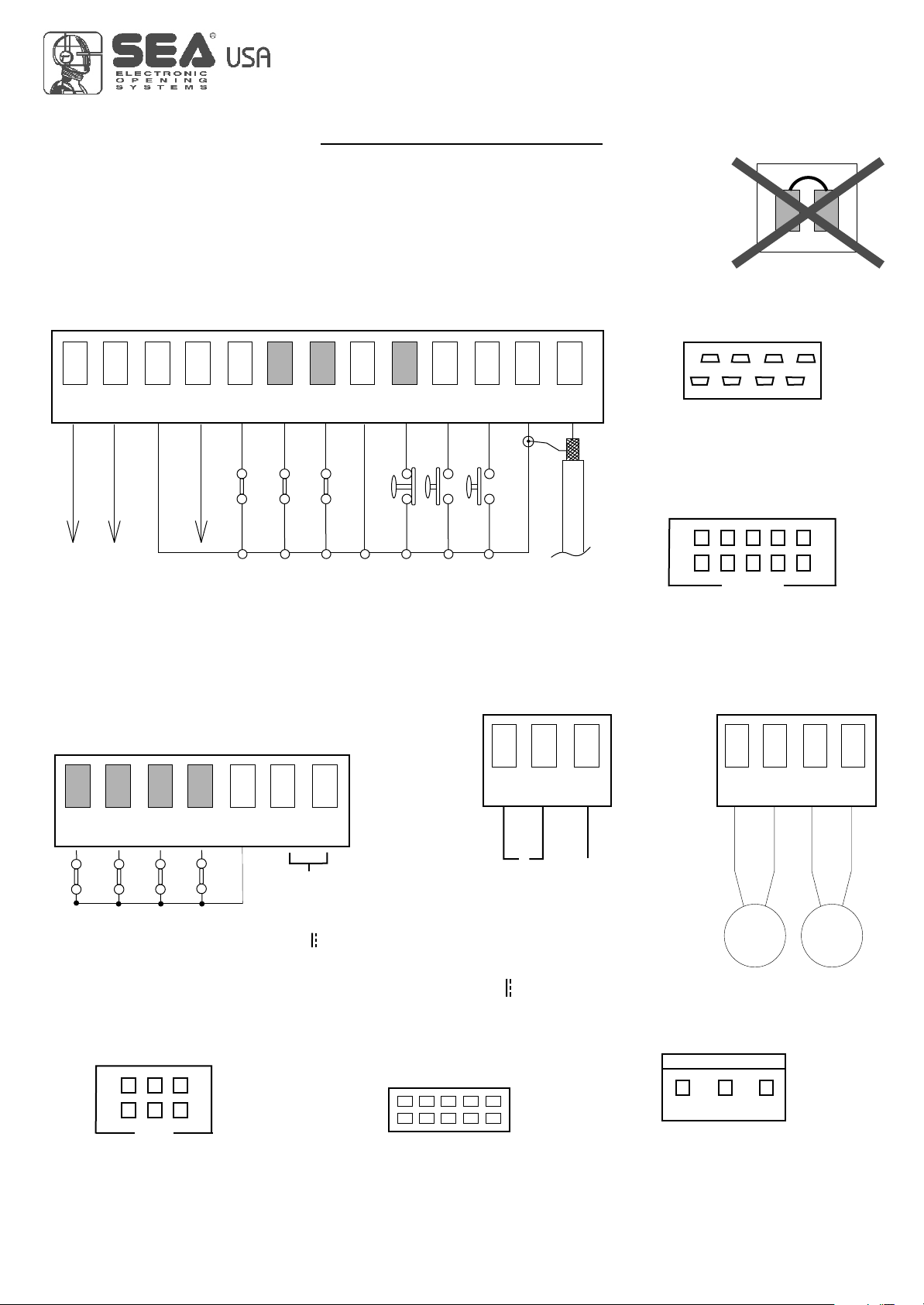
CONNECTIONS
WARNING: The control unit is designed with the automatic detection of not used
N.C. inputs (photocells, Stop and Limit switch) except the SAFETY EDGE input.
“ALL IN”
13
Flash (-)
12
Max 600 mA
24VL (Flash)
11 10
24V Aux
Common
CN2
(250 mA max)
9 8
Edge
CN1
7 6
Photocell 2
Common
Photocell 1
5
Stop
4
START Ped.
3
Start
2
Common
CN5
1
Antenna
RADIO MODULE (CNA)
Receiver module connector
JOLLY
Connector Programmer Jolly
CN3
15
14
M1
ing
L o imit Switch pen
16 17
los 1mi witch c ing M
Li t S
LmiS th eigM2i t wic opnn
EXP
Connector External Module
18 19
o i
Limi Sw t h l s ng M2 t i c c
Common
20
Electric lock
(12V 15VA max)
PROG
connectorProgramming
S
+
P s iv ba teo it e t ry
28V Battery chargert
-
g rga iv a ter c ar e
23
24
25 26
M1 M2
e t e b t y h
N
POWER
24V~ Power connector
REV 01 - 06/201467411656
5
USER 2 - 24V DG
“ALL IN”
International registered trademark n. 2.777.971
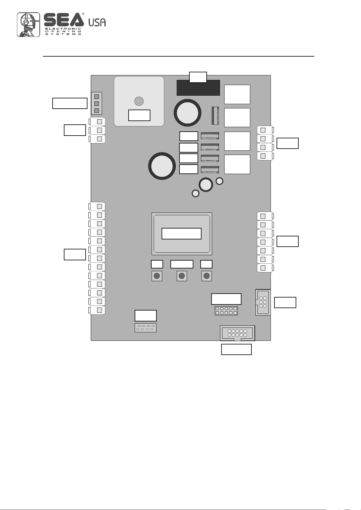
DESCRIPTION OF THE COMPONENTS
F1
RL1
POWER
CN5
CN1
+ S -
13 12 11 10 9 8 7 6 5 4 3 2 1
PR1
MF4
MF3
MF2
MF1
RL2
RL3
RL4
CN3
23 24 25 26
DISPLAY
CN2
UP DOWN OK
14 15 16 17 18 19 20
CNA
CN1 = Input/Output connector
CN2 = Limit switch, electro-lock connector
CN3 = Motors connector
CN5 = Battery charger connector
CNA = Receiver module connection
EXP = External module connector
JOLLY = Jolly programmer connector
PROG
EXP
JOLLY
MF1 - MF2 = Mosfet motor 2
MF3 - MF4 = Mosfet motor 1
POWER = 24V~ power supply connection
PROG = Programming connector
Pr1 = Rectifier jumper
RL1 - RL2 = Relay motor 2
RL3 - RL4 = Relay motor 1
F1 = Fuse 10AT
6
REV 01 - 06/201467411656
USER 2 - 24V DG
“ALL IN”
International registered trademark n. 2.777.971
GENERAL INFORMATION
The information in this section of the manual are only for technicians or for qualified or authorized
installers.
GENERAL CHARACTERISTICS
The USER 2 24V DG “ALL IN” control unit has been designed to manage one or two low voltage swing gate
operators with or without electronic limit switches.
It is of very small dimensions and besides the possibility to adjust motor speed, amperemetric anti squeezing
sensitivity, leaf delay in closing, pausing time, it is also possible to manage a display, through which it is possible to
control a lot of management functions and the maintenance of the control unit.
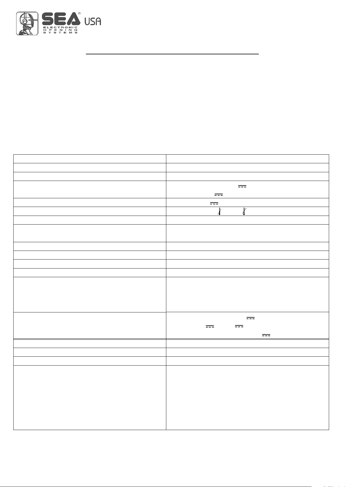
TECHNICAL SPECIFICATIONS
Control unit power supply
Absorption in stand by
Max. motor charge
Max. accessories charge
Max. Flash light charge
Environment temperature
Protection fuse
Function logic
Opening/closing time
Time of pause
Thrust
Slow down
Input on connecting terminal
Output on connecting terminal
Board dimensions
Specifications of optional batteries
Specifications of external enclosure
Special accessories
24V~
30mA
150 W x 2
24Aux (250mA) (Programmable) /
24VL (600mA) (Accessories and Flashing lamp)
24VL (Flashing lamp) 15W max.
20°C +50°C (-4°F + 122°F)
10AT
Automatic / Step by step type 1 / Step by step type 2
/ Safety / Dead man / 2 Buttons.
In selflearning in programming phase
Adjustable
Adjustable for single leaf and direction
Adjustable for single leaf and direction
Battery power supply / Total opening / Pedestrian
opening adjustable / Edge (opt.8K2)/
Stop / Limit switch opening and closing / Encoder /
Photcell in opening and closing
Power supply 24Aux (Programmable) /
Motors 24V / 24VL Accessories and Flashing
lamp / Electro-lock 12V 15VA Max
156 x 100 mm
24V Pb 2Ah min.
305 x 225 x 125 mm (12 x 8 x 5 inches) - Ip55
Battery charger card (code 23101105)
Relay card for traffic light management
(SEM Cod. 23021100)
Programmer JOLLY (code 23105276)
Programmer JOLLY2 (cod.23105277)
Programmer OPEN (code 23105290)
Display BINGO (cod.23101131)
NOTE: The Jolly programmer will be functioning starting from Rev. 35 onwards. You can upgrade the
software of the Jolly and the control units with the OPEN device and the update firmware software.
The herein reported functions are available starting from revision 018.
REV 01 - 06/201467411656
7
International registered trademark n. 2.777.971
USER 2 - 24V DG
“ALL IN”
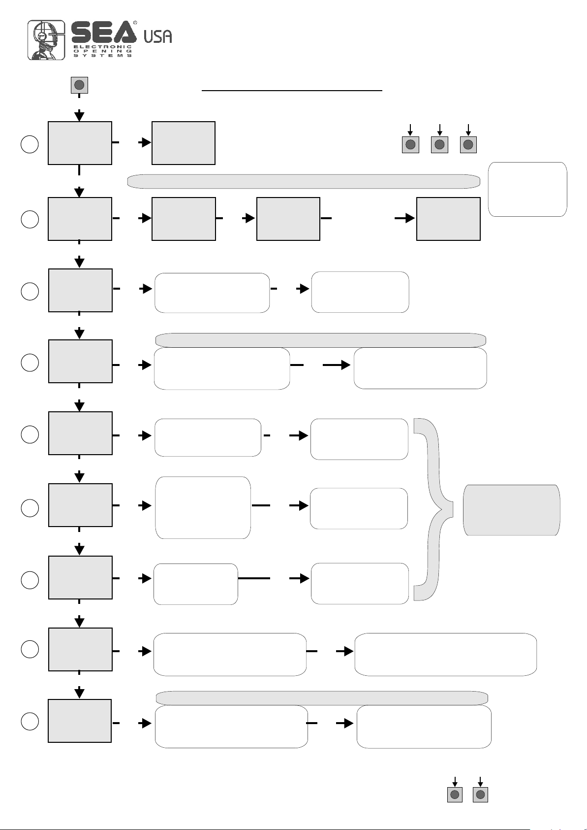
QUICK START
MENU
1
LANGUAGE
MENU
2
TRANSMITTERS
MENU
3
MENU
ONE SINGLE
4
UP
SEA
UP
SEA
UP
SEA
MOTOR
UP
SEA
LEAF
UP
SET
OK
SEA
MENU
ITALIANO
SET
Skip this step if you do not want to program a transmitter
SET
OK
SET
OK
SEA
MENU
SET
START
Choose the type of
motor with
UP or DOWN
MENU
OK
Skip this step if you are working in double leaf mode
SET
OK OK
With UP or DOWN choose
ON only if in single
leaf mode
SEA
PRESS
BUTTON
OK
SET
Press the
button of the
TX to be
stored
To confirm and return
to main menu
To confirm and return
to the main menu
PROGRAMMING
BUTTONS
DOWNUP
MENU
STORED
SEA
OK
SET
OK to exit Menu
or press the
button of the next
TX to be stored
MENU
5
MENU
6
PAUSE TIME
MENU
7
MENU
PROGRAM-
8
MENU
9
TEST START
SEA
LOGIC
UP
SEA
UP
SEA
START IN
PAUSE
UP
SEA
MING
UP
SEA
SET
OK OK
With UP or DOWN
choose
the desired logic
SET
OK OK
With UP or DOWN
choose a delay for
automatic closing
SET
OK OK
With UP or DOWN
Choose ON
SET
OK OK
With UP or DOWN choose ON
to start times learning
Skip this step if a TX has already been stored
SET
OK OK
UP or DOWN Choose
With
ON to start test
To confirm and return
to main menu
To confirm and return
to main menu
To confirm and return
to main menu
At the end of the selflearning
the control unit returns automatically
To confirm and return to
main menu
Skip this step
if you wna tto work
in half-automatic
logic
to the main menu
ALL OTHER PARAMETERS HAVE DEFAULT SETTINGS WHICH ARE USEFUL FOR THE 90% OF THE
APPLICATIONS BUT CAN BE HOWEVER SET THROUGH THE SPECIAL MENU. FOR ENTERING INTO THE
SPECIAL MENU PRESS THE UP AND DOWN BUTTONS AT THE SAME TIME FOR 5 S.
8
REV 01 - 06/201467411656
UPDOWN
 Loading...