

SEA USER 1-24V DG R1B User Manual
International registered trademark n. 2.777.971
USER 1 - 24V DG R1B
24V ELECTRONIC CONTROL UNIT FOR SLIDING GATES AND BARRIERS
SEA USA Inc.
10850 N.W. 21st unit 160 DORAL MIAMI
Florida (FL) 33172 USA
:++1-305.594.1151 ++1-305.594.7325
Tel. -
Toll free:
web site: www.sea-usa.com
e-mail: sales@sea-usa.com
67411535 REV 08 - 12/2015
800.689.4716

USER 1 - 24V DG R1B
International registered trademark n. 2.777.971
Details
General
An appliance shall be provided with an instruction manual. The instruction manual shall give instructions for the installation,
operation, and user maintenance of the appliance.
The installation instructions shall specify the need for a grounding-type receptacle for connection to the supply and shall stress the
importance of proper grounding.
The installation instructions shall inform the installer that permanent wiring is to be employed as required by local codes, and
instructions for conversion to permanent wiring shall be supplied.
Information shall be supplied with a gate operator for:
a) The required installation and adjustment of all devices and systems to effect the primary and secondary protection against
entrapment (where included with the operator).
b) The intended connections for all devices and systems to effect the primary and secondary protection against entrapment. The
information shall be supplied in the instruction manual, wiring diagrams, separate instructions, or the equivalent.
Vehicular gate operators (or systems)
A vehicular gate operator shall be provided with the information in the instruction manual that defines the different vehicular gate
operator Class categories and give examples of each usage. The manual shall also indicate the use for which the particular unit is
intended as defined in Glossary, Section 3. The installation instructions for vehicular gate operators shall include information on
the Types of gate for which the gate operator is intended.
A gate operator shall be provided with the specific instructions describing all user adjustments required for proper operation of the
gate. Detailed instructions shall be provided regarding user adjustment of any clutch or pressure relief adjustments provided. The
instructions shall also indicate the need for periodic checking and adjustment by a qualified technician of the control mechanism
for force, speed, and sensitivity.
Instructions for the installation, adjustment, and wiring of external controls and devices serving as required protection against
entrapment shall be provided with the operator when such controls are shipped with the operator.
Instructions regarding intended installation of the gate operator shall be supplied as part of the installation instructions or as a
separate document. The following instructions or the equivalent shall be supplied where applicable:
a) Install the gate operator only when:
1) The operator is appropriate for the construction of the gate and the usage Class of the gate,
2) All openings of a horizontal slide gate are guarded or screened from the bottom of the gate to a minimum of 4 feet (1.22
m) above the ground to prevent a 2-1/4 inch (57.2 mm) diameter sphere from passing through the openings anywhere in
the gate, and in that portion of the adjacent fence that the gate covers in the open position,
3) All exposed pinch points are eliminated or guarded, and
4) Guarding is supplied for exposed rollers.
b) The operator is intended for installation only on gates used for vehicles. Pedestrians must be supplied with a separate access
opening. The pedestrian access opening shall be designed to promote pedestrian usage. Locate the gate such that persons will
not come in contact with the vehicular gate during the entire path of travel of the vehicular gate.
c) The gate must be installed in a location so that enough clearance is supplied between the gate and adjacent structures when
opening and closing to reduce the risk of entrapment. Swinging gates shall not open into public access areas.
d) The gate must be properly installed and work freely in both directions prior to the installation of the gate operator. Do not overtighten the operator clutch or pressure relief valve to compensate for a damaged gate.
e) (not applicable)
f) Controls intended for user activation must be located at least six feet (6’) away from any moving part of the gate and where the
user is prevented from reaching over, under, around or through the gate to operate the controls. Outdoor or easily accessible
controls shall have a security feature to prevent unauthorized use.
2

USER 1 - 24V DG R1B
International registered trademark n. 2.777.971
g) The Stop and/or Reset button must be located in the line-of-sight of the gate. Activation of the reset control shall not cause the
operator to start.
h) A minimum of two (2) WARNING SIGNS shall be installed, one on each side of the gate where easily visible.
i) For gate operators utilizing a non-contact sensor:
1) See instructions on the placement of non-contact sensors for each Type of application,
2) Care shall be exercised to reduce the risk of nuisance tripping, such as when a vehicle, trips the sensor while the gate is
still moving, and
3) One or more non-contact sensors shall be located where the risk of entrapment or obstruction exists, such as the
perimeter reachable by a moving gate or barrier.
j) For a gate operator utilizing a contact sensor:
1) One or more contact sensors shall be located where the risk of entrapment or obstruction exists, such as at the leading
edge, trailing edge, and postmounted both inside and outside of a vehicular horizontal slide gate.
2) One or more contact sensors shall be located at the bottom edge of a vehicular vertical lift gate.
3) One or more contact sensors shall be located at the pinch point of a vehicular vertical pivot gate.
4) A hardwired contact sensor shall be located and its wiring arranged so that the communication between the sensor and
the gate operator is not subjected to mechanical damage.
5) A wireless contact sensor such as one that transmits radio frequency (RF) signals to the gate operator for entrapment
protection functions shall be located where the transmission of the signals are not obstructed or impeded by building
structures, natural landscaping or similar obstruction. A wireless contact sensor shall function under the intended enduse conditions.
6) One or more contact sensors shall be located on the inside and outside leading edge of a swing gate. Additionally, if the
bottom edge of a swing gate is greater than 6 inches (152 mm) above the ground at any point in its arc of travel, one or
more contact sensors shall be located on the bottom edge.
Revised 56.8.4 effective February 21, 2008
7) One or more contact sensors shall be located at the bottom edge of a vertical barrier (arm).
Instruction regarding intended operation of the gate operator shall be provided as part of the user instructions or as a separate
document. The following instructions or the equivalent shall be provided:
IMPORTANT SAFETY INSTRUCTIONS
WARNING – To reduce the risk of injury or death:
ATTENTION: pour réduire le risque de dommages ou mort:
1. READ AND FOLLOW ALL INSTRUCTIONS.
2. Never let children operate or play with gate controls. Keep the remote control away from children.
3. Always keep people and objects away from the gate. NO ONE SHOULD CROSS THE PATH OF THE MOVING GATE.
4. Test the gate operator monthly. The gate MUST reverse on contact with a rigid object or stop when an object activates the noncontact sensors. After adjusting the force or the limit of travel, retest the gate operator. Failure to adjust and retest the gate
operator properly can increase the risk of injury or death.
5. Use the emergency release only when the gate is not moving.
6. KEEP GATES PROPERLY MAINTAINED. Read the owner’s manual. Have a qualified service person make repairs to gate
hardware.
7. The entrance is for vehicles only. Pedestrians must use separate entrance.
8. SAVE THESE INSTRUCTIONS.
3
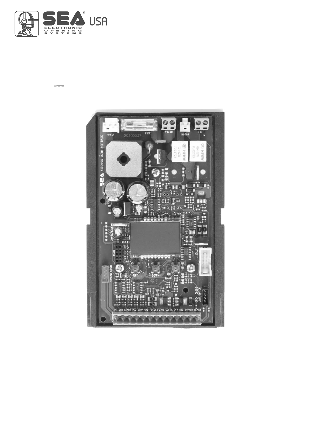
DESCRIPTION OF THE COMPONENTS
TECHNICAL SPECIFICATIONS
Control unit power supply: 24 V~
Absorption in stand by: 30 mA
Environment temperature: -20 +55 (-4°F +122°F)
Specifications of external enclosure: 305 x 225 x 125 mm (12 x 9 x 5 inches) - Ip55
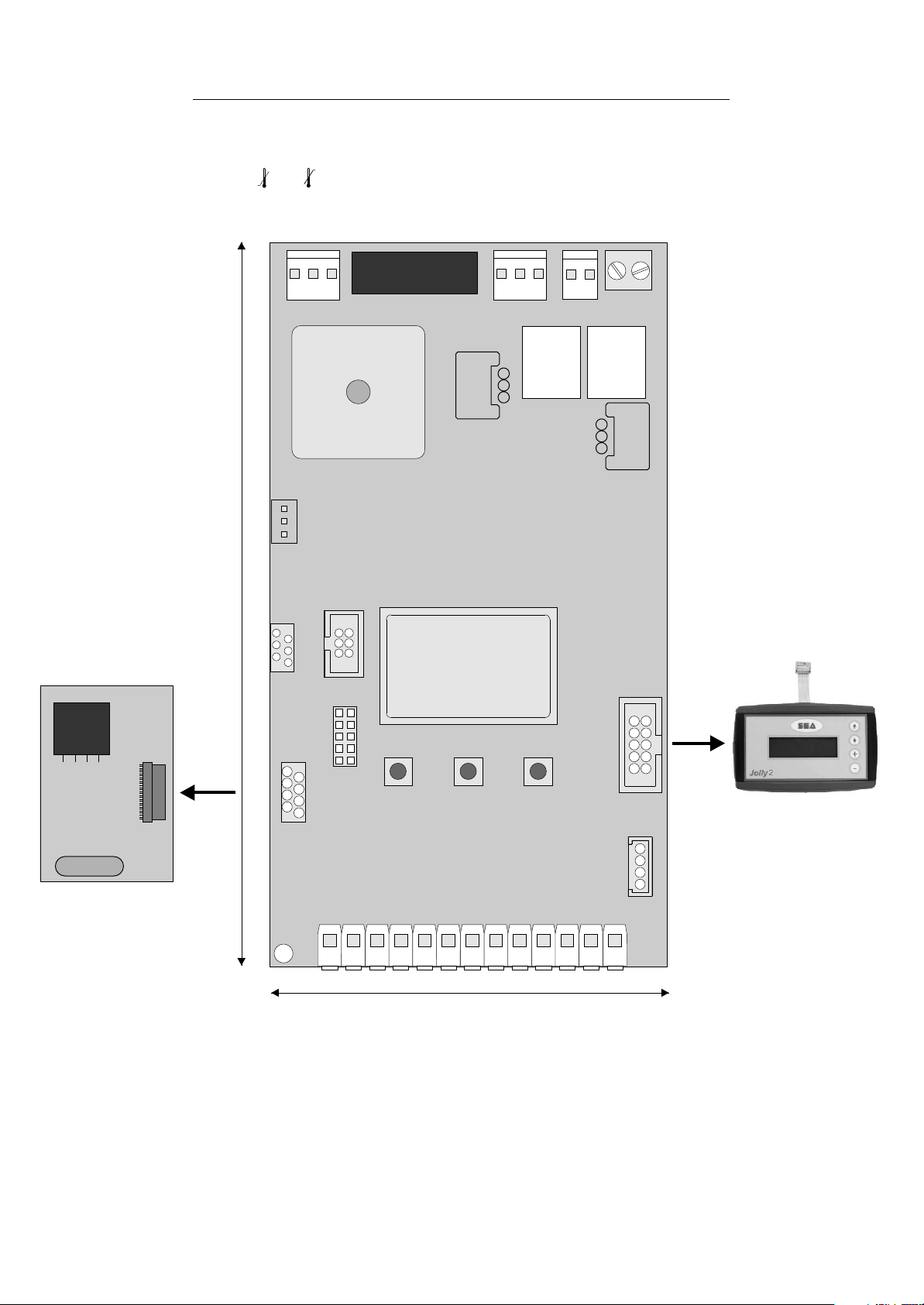
USER 1 - 24V DG R1B
RECEIVER RX
156 mm
1
CNE
CN4
CN8
POWER
ENCODER
MASTER/SLAVE
PROG
PR1
EXP
CNP
F1
FUSE
DISPLAY
RD1
CN7
BATTERY
RL1
CN6
MOTOR
CN5
LIGHT
RL2
RD3
CN3
CNA
RADIO MODULE
UP
DOWN
OK
JOLLY
JOLLY-JOLLY2
CN2
LIMIT SWITCH
CN1
1
1 2 3 4 5 6 7 8 9 10 11 12 13
100 mm
CN1 = Input/Output connector
CN2 = Limit switch connector
CN3 = Jolly-Jolly 2 connector
CN4 = Master/slave connector
CN5 = Courtesy light output plug
CN6 = Motors connector
CN7 = Batteries connector - Quick connection
CN8 = Power connector
CNA = RX Receiver connector
CNE = Encoder connector
4
CNP = Programming connector
EXP = External module connector
OK = Programming button
DOWN = Programming button
UP = Programming button
RD1 =Motors piloting Mosfet
RD3 = Motors piloting Mosfet
R1 = Motors command relay
R2 = Motors command relay
PR1 = Rectifier jumper
F1 = Fuse 10 AT
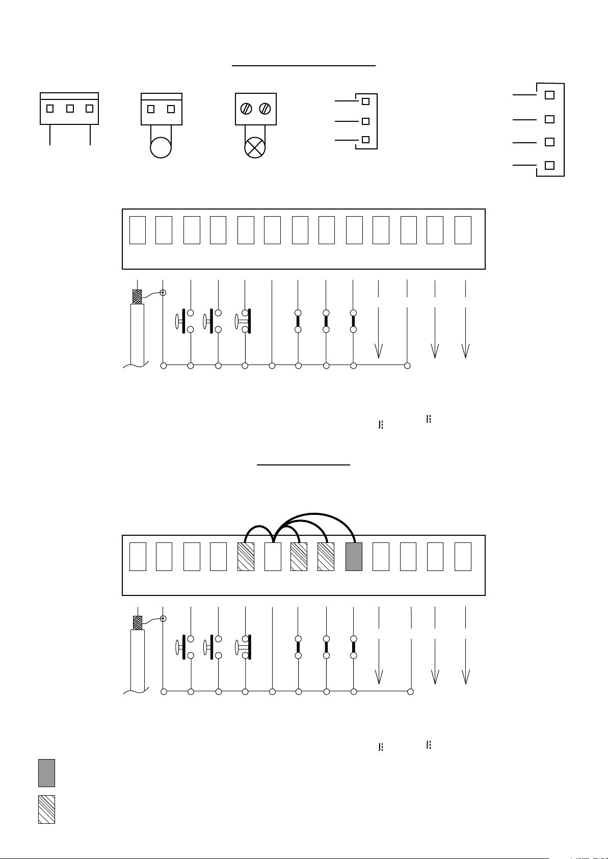
POWER (CN8)
MOTOR (CN6)
CONNECTIONS
LIGHT (CN5)
Brown
1
USER 1 - 24V DG R1B
ENCODER (CNE)
24V (Red)
LIMIT SWITCH (CN2)
24V~
M
Max 200W
2
1
ANT COM START
Antenna
3 4
Start
Common
Max 100mA
5 6
PEDST
STOP COM PH1 PH2
Stop
Common
START Ped.
White
Green
CN1
7 8
Photocell 1
Limit switch Cl.1 (Yellow)
Limit switch Op.1 (Green)
Common (White)
1
9
10
EDGE
AUX
+ +
Photocell 2
Safety edge
AUX Programmable
(24V 300 mA max)
12
11
COM 24V (FL)-
- -
Common
13
(Accessori)
24V 750 mA max
Flash (-)
JUMPERS
WARNING: The control unit is designed with the automatic detection of not used N.C. inputs (photocells, Stop and Limit switch) except the
SAFETY EDGE input. The exclude inputs in self-programming can be restored in the “Check inputs” menu without need to repeat the
programming (pag.14).
CN1
2
1
ANT COM START
Antenna
Obligatory jumper without accessory connection.
Optional
Common
3 4
PEDST
Start
5 6
STOP COM PH1 PH2
Stop
START Ped.
Common
7 8
Photocell 1
Photocell 2
9
EDGE
Safety edge
10
11
AUX
COM 24V (FL)-
+ +
AUX Programmable
- -
Common
(24V 300 mA max)
12
13
Flash (-)
(Accessori)
24V 750 mA max
The herein reported functions
are available starting from
revision 73.
5
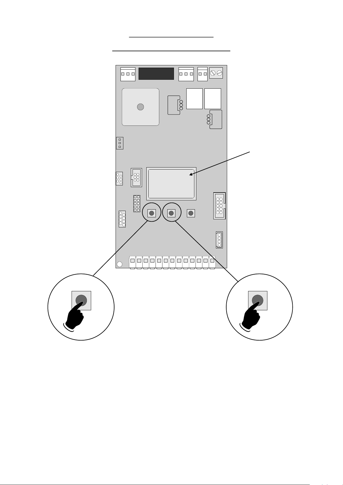
PROGRAMMING
FAST SELF-LEARNING
DISPLAY
---
--
---
UP
DOWN
OK
USER 1 - 24V DG R1B
nput check
“I
menu
"
1 2 3 4 5 6 7 8 9 10 11 12 13
UP DOWN
5 s 5 s
Start quick programming
You can start the quick programming by
holding UP for 5 s in the “I
menu
", until the motor starts.
nput check
Fast self-learning START command by
radio control
You can store the START button of the
remote control while pressing DOWN for 5 s
in the “I ".
Once the writing "Press button" appears,
press the button of the transmitter, which
you want to store for the START command.
By pressing OK, you can exit the menu,
otherwise it will be left automatically after 5
seconds.
nput check menu
6

PROGRAMMING
USER 1 - 24V DG R1B
1
2
3
5
6
(See
page 8)
UP
SEA
MENU
SET
LANGUAGE
UP
SEA
MENU
SET
TRANSMITTERS
UP
SEA
MENU
SET
MOTOR
UP
SEA
MENU
SET
REVERSE
MOTOR
UP
SEA
MENU
SET
LOGIC
UP
QUICK START
SEA
MENU
OK
ITALIANO
Skip this step if you do not want to program a transmitter
MENU
OK
If on the display
appears the item:
OK
programming the motor starts
OK OK
SET
SEA
START
MENU
SET
SEA
RECEIVER
MISSING
OK
SET
MENU
BUTTON
Check if a receiver has
been connceted
(see page 4)
Choose the type of
motor with
UP or DOWN
Choose "ON" with UP or
DOWN button only if in
in opening
With UP or DOWN
choose
the desired logic
PRESS
OKOK
SEA
SET
button of the
To confirm and return
to main menu
OK
To confirm and return
to main menu
Press the
TX to be
stored
Return to menu 7,
place the gate halfway
and repeat
the times programming
PROGRAMMING
BUTTONS
SEA
MENU
SET
STORED
If the motor has
magnetic limit switches,
select "Magnetic"
in the special menu:
104 - SELECT LIMIT SWITCH
OK to exit
Menu or press
the button of
the next TX to
be stored
DOWNUP
OK
7
8
9
(See
page 8)
10
15
SEA
MENU
SET
PAUSE TIME
UP
SEA
MENU
SET
START IN
PAUSE
UP
SEA
MENU
SET
PROGRAM-
MING
UP
SEA
MENU
SET
TEST START
UP
SEA
MENU
SET
END
OK OK
choose a delay for
With UP or DOWN
To confirm and return
automatic closing
With UP or DOWN
OK OK
To confirm and return
Choose ON
OK OK
With UP or DOWN choose ON
to start times learning
The gate will execute a CLOSING-OPENING-CLOSING CYCLE
Skip this step if a TX has already been stored
OK OK
UP or DOWN Choose
OK
With
ON to start test
Press OK to return to the
display of the inputs state.
to main menu
to main menu
At the end of the selflearning
the control unit returns automatically
To confirm and return to
Skip this step
if you wna tto work
in half-automatic
logic
to the main menu
main menu
UP
SEA
16
MENU
SPECIAL
MENU
SET
OK
Press OK to enter the special menu.
ALL OTHER PARAMETERS HAVE DEFAULT SETTINGS WHICH ARE USEFUL FOR THE 90% OF THE APPLICATIONS
BUT CAN BE HOWEVER SET THROUGH THE SPECIAL MENU. FOR ENTERING INTO THE SPECIAL MENU MOVE
ON ONE OF THE MENU AND PRESS THE UP AND DOWN BUTTONS AT THE SAME TIME FOR 5 S.
UPDOWN
7
USER 1 - 24V DG R1B
MENU FUNCTIONS TABLE USER1 24V DG R1B
MENU
1 - LANGUAGE
2 - TRANSMITTERS
3 - MOTOR
5 - REVERSE MOTOR
6 - LOGIC
(See page 9)
7 - PAUSE TIME
8 - START IN PAUSE
9 - PROGRAMMING
(See page 9)
10 - TEST START
15 - END
16 - SPECIAL MENU
8
SET
Italiano
English
Français
Español
Dutch
Start
Pedestrian Start
External module
Stop
Unloch
Delete a transmitter
Clear memory
End
Sliding
Saturn Fast - Saturn Super Fast
Joint
Sprint 3 meters
Sprint 4 meters
Sprint 5 meters
Storm 5 meters
Storm 6 meters
Storm 7,5 meters
Saturn
Mercury 800
VergL.5 meters
VergL.4 meters
VergL.3 meters
Erg Maxi
Erg
Verg
Reversible sliding gate
Mercury Fast Mercury Fast
Saturn 1500
Off
On
Automatic
Open-stop-close-stop-open
Open-stop-close-open
2 buttons
Safety
Dead man
Off
1 240
Off
On
Off On
Off On
Press OK to return to the display of the firmware version and to the one of inputs state.
Press OK to enter the special menu.
Italian
English
French
Spanish
Olandese
Start
Pedestrian Start
External module
Stop
Storing of a command for
unlocking an electric brake
Delete single transmitter
Delete transmitter memory
“Transmitters” menu output
Sliding/B 200/B 500
Saturn Fast - Saturn Super Fast
Joint
Sprint 3 meters
Sprint 4 meters
Sprint 5 meters
Storm 5 meters
Storm 6 meters
Storm 7 and 7.5 meters
Saturn
Mercury 800
VergL.5 meters
VergL.4 meters
VergL.3 meters
Erg Maxi
Erg
Verg
C500 - Puma
Saturn 1500
Synchronized right motor
Synchronized left motor
Automatic
Step by step type 1
Step by step type 2
Two buttons
Safety
Dead man
OFF
(semi-automatic logics)
Setting from 1s to 4min.
In pause start is not acceped
In pause start is accepted
Times learning start
Start command
Description
Default
Italiano
Start
Pedestrian
Start
Sliding
Off
Open-stopclose-open
Off
Off
Off
Off
Set value
 Loading...