

SEA User 1 24V DG R1 User Manual
®
Sistemi Elettronici
di Apertura Porte e Cancelli
International registered trademark n. 804888
Italiano
English
USER 1 - 24V DG R1
Français
Español
23024055
APPAR. ELETTRONICA 24V PER CANCELLI SCORREVOLI E BARRIERA
24V ELECTRONIC CONTROL UNIT FOR SLIDING GATES AND BARRIERS
ARMOIRE ELECTRONIQUE 24V POUR PORTAILS COULISSANTS ET BARRIERES
DISPOSITIVO ELECTRÓNICO 24V PARA CANCELAS CORREDIZOS Y BARRERAS
67411260
SEA S.p.A.
Zona Ind.le S. Atto - 64020 S. Nicolò a Tordino (TE)
Tel. 0861.588341 - Fax 0861.588344
www.seateam.com
e-mail: seacom@seateam.com
REV. 08 - 10/2014
®
Sistemi Elettronici
di Apertura Porte e Cancelli
International registered trademark n. 804888
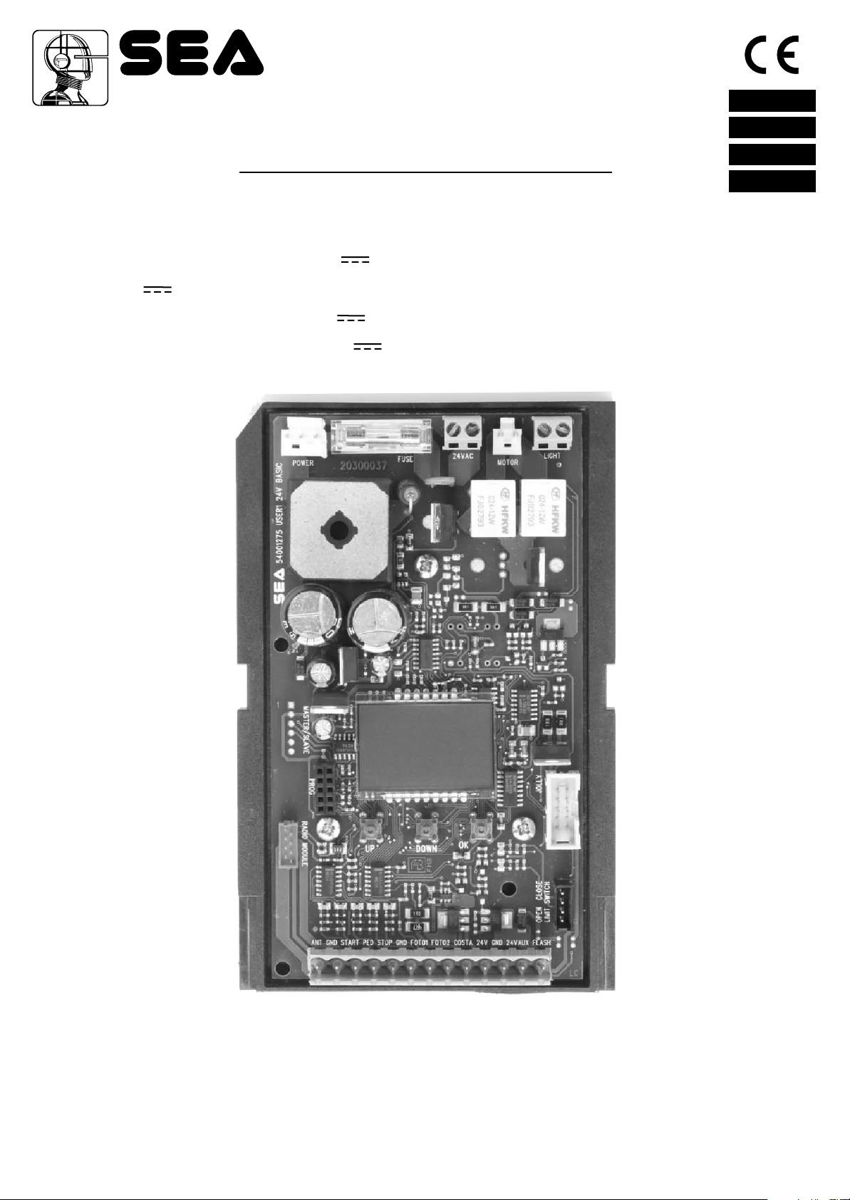
DESCRIPTION OF THE COMPONENTS
TECHNICAL SPECIFICATIONS
24 V~
Control unit power supply
Absorption in stand by
Environment temperature
Specifications of external enclosure
:
30 mA
:
-20°C +50°C
:
English
305 x 225 x 125 mm - Ip55
:
USER 1 - 24V DG R1
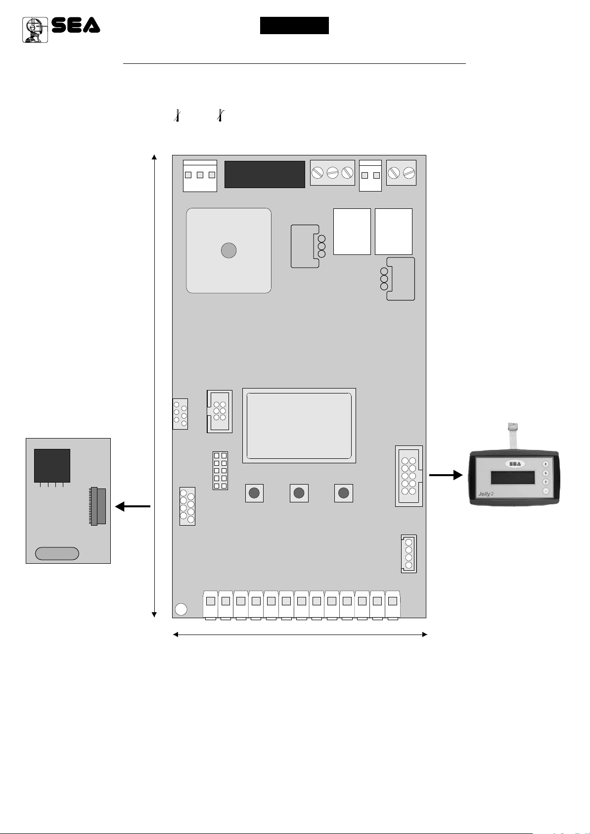
RECEIVER RX
156 mm
CN4
CN8
POWER
MASTER/SLAVE
PROG
PR1
EXP
CNP
F1
FUSE
DISPLAY
RD1
CN7
- S +
BATTERY
RL1
CN6
MOTOR
CN5
LIGHT
RL2
RD3
CN3
67411260
CNA
RADIO MODULE
1 2 3 4 5 6 7 8 9 10 11 12 13
CN1 = Input/Output connector
CN2 = Limit switch connector
CN3 = Jolly-Jolly 2 connector
CN4 = Master/slave connector
CN5 = Courtesy light output plug
CN6 = Motors connector
CN7 = Batteries connector
CN8 = Power connector
CNA = RX Receiver connector
CNP = Programming connector
UP
DOWN
100 mm
REV. 08 - 10/2014
CN1
JOLLY
OK
JOLLY-JOLLY2
CN2
LIMIT SWITCH
1
EXP = External module connector
OK = Programming button
DOWN = Programming button
UP = Programming button
RD1 =Motors piloting Mosfet
RD3 = Motors piloting Mosfet
R1 = Motors command relay
R2 = Motors command relay
PR1 = Rectifier jumper
F1 = Fuse 10 AT
19
®
Sistemi Elettronici
di Apertura Porte e Cancelli
International registered trademark n. 804888
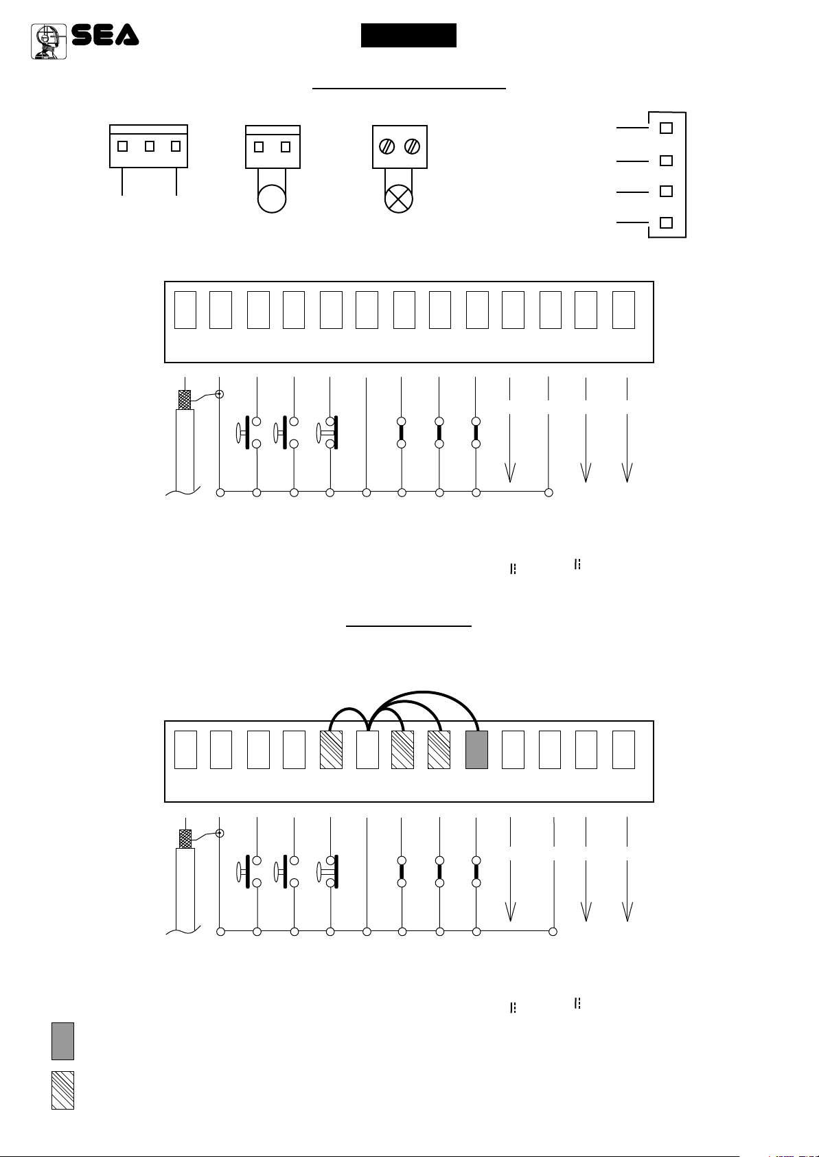
POWER (CN8)
CONNECTIONS
MOTOR (CN6)
English
LIGHT (CN5)
USER 1 - 24V DG R1
LIMIT SWITCH (CN2)
24V (Red)
Limit switch Cl.1 (Yellow)
24V~
1
ANT COM START
M
Max 200W
Max 100mA
Limit switch Op.1 (Green)
Common (White)
1
CN1
2
3 4
Start
Antenna
Common
5 6
PEDST
STOP COM PH1 PH2
Stop
START Ped.
Common
7 8
Photocell 1
9
10
EDGE
AUX
+ +
AUX
Photocell 2
Safety edge
(24V 200 mA max)
12
11
COM 24V (FL)-
- -
Common
13
(Accessori)
24V 750 mA max
Flash (-)
JUMPERS
WARNING: The control unit is designed with the automatic detection of not used N.C. inputs (photocells, Stop and Limit switch) except the
SAFETY EDGE input. The exclude inputs in self-programming can be restored in the “Check inputs” menu without need to repeat the
programming (pag.28).
CN1
2
1
ANT COM START
Antenna
Obligatory jumper without accessory connection.
Optional
Common
3 4
PEDST
Start
5 6
STOP COM PH1 PH2
Stop
START Ped.
Common
7 8
Photocell 1
Photocell 2
9
EDGE
Safety edge
10
11
AUX
COM 24V (FL)-
+ +
AUX
- -
Common
(24V 200 mA max)
12
13
Flash (-)
(Accessori)
24V 750 mA max
The herein reported functions
are available starting from
revision 55.
20
67411260
REV. 08 - 10/2014
1
®
Sistemi Elettronici
di Apertura Porte e Cancelli
International registered trademark n. 804888
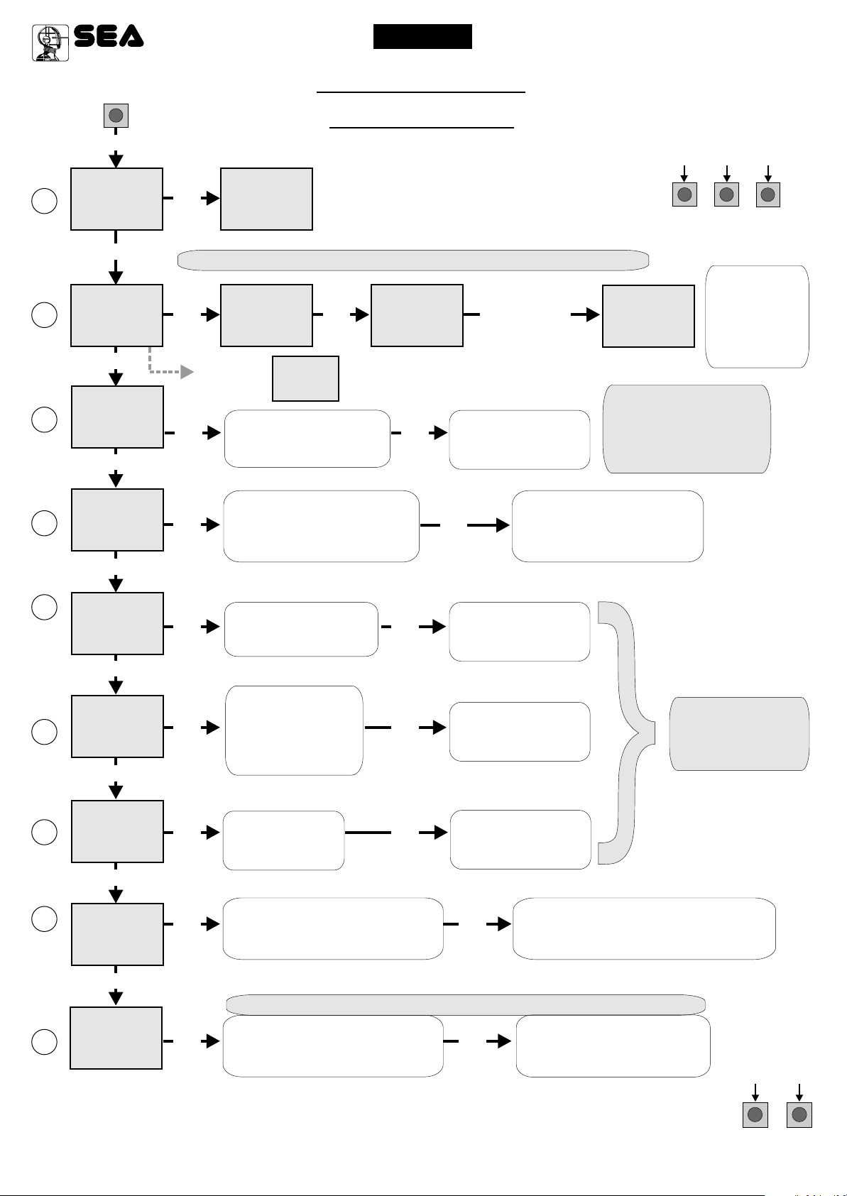
UP
SEA
MENU
LANGUAGE
SET
OK
SEA
MENU
ITALIANO
English
PROGRAMMING
QUICK START
SET
USER 1 - 24V DG R1
PROGRAMMING
BUTTONS
DOWNUP
OK
2
3
4
5
(See
page 22)
UP
SEA
MENU
SET
TRANSMITTERS
UP
SEA
MENU
SET
MOTOR
UP
SEA
MENU
SET
REVERSE
MOTOR
UP
SEA
MENU
SET
LOGIC
UP
Skip this step if you do not want to program a transmitter
SEA
MENU
OK
If on the display
appears the item:
START
Choose "ON" with UP or
OK
programming the motor starts
With UP or DOWN
OK OK
SET
MENU
OK
SEA
MENU
RECEIVER
MISSING
Choose the type of
motor with
UP or DOWN
DOWN button only if in
in opening
choose
the desired logic
Check if a receiver has
SET
been connceted
(see page 19)
PRESS
BUTTON
OKOK
SEA
SET
Press the
button of the
TX to be
stored
To confirm and return
to main menu
Return to menu 7,
OK
place the gate halfway
the times programming
To confirm and return
to main menu
SEA
MENU
SET
STORED
If the motor has
magnetic limit switches,
select "Magnetic"
in the special menu:
34-Limit switch type
and repeat
OK to exit
Menu or press
the button of
the next TX to
be stored
MENU
PAUSE TIME
6
SEA
SET
OK OK
With UP or DOWN
choose a delay for
automatic closing
To confirm and return
to main menu
Skip this step
if you wna tto work
in half-automatic
logic
UP
SEA
MENU
7
START IN
PAUSE
SET
OK OK
With UP or DOWN
Choose ON
To confirm and return
to main menu
UP
8
(See
page 22)
SEA
MENU
PROGRAM-
MING
SET
OK OK
With UP or DOWN choose ON
to start times learning
The gate will execute a CLOSING-OPENING-CLOSING CYCLE
At the end of the selflearning
the control unit returns automatically
to the main menu
UP
SEA
MENU
9
TEST START
ALL OTHER PARAMETERS HAVE DEFAULT SETTINGS WHICH ARE USEFUL FOR THE 90% OF THE APPLICATIONS
BUT CAN BE HOWEVER SET THROUGH THE SPECIAL MENU. FOR ENTERING INTO THE SPECIAL MENU MOVE
67411260
SET
OK OK
ON ONE OF THE MENU AND PRESS THE UP AND DOWN BUTTONS AT THE SAME TIME FOR 5 S.
UP or DOWN Choose
Skip this step if a TX has already been stored
With
ON to start test
REV. 08 - 10/2014
To confirm and return to
main menu
UPDOWN
21

Sistemi Elettronici
di Apertura Porte e Cancelli
International registered trademark n. 804888
®
English
USER 1 - 24V DG R1
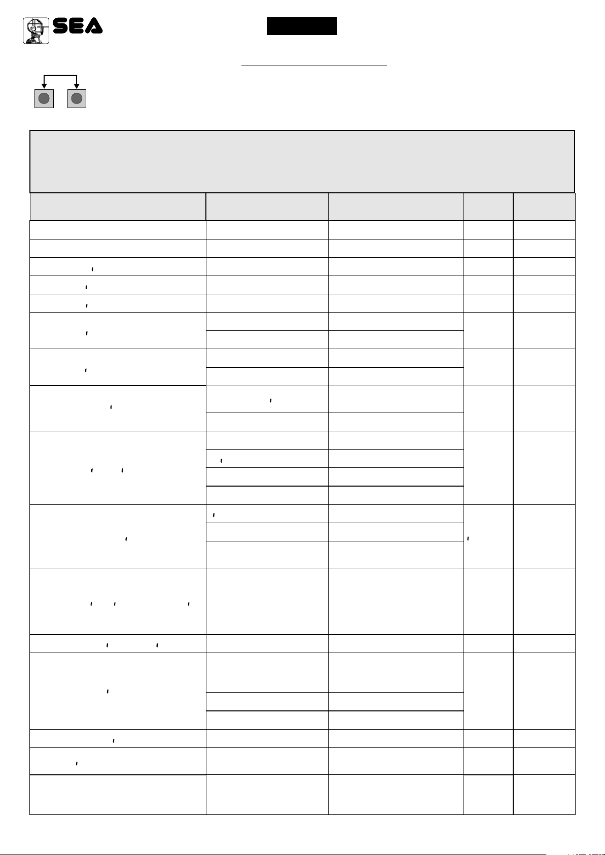
MENU FUNCTIONS TABLE USER1 24V DG R1
MENU
1 - langvage
U
2 - trans tters
3 - otor
U
4 - reuerse otor
5 - log (
(See page 23)
6 - paVse t e
7 - starT n pavse
8 - progra ng
(See page 23)
9 - test start
end
22
67411260
SET
tal ano
engl sk
fran(a s
espanol
dut(k
start
Pedestr an Start
U
External odvle
stop
U
Delete a trans itter
UU
(Lear e ory
Sl d ng
Satvrn fast
Jo nt
U
Spr nt 3 eters
Spr nt 4 eters
Spr nt 5 eters
U
U
U
U
Stor 5 eters
U
U
Stor 6 eters
U
U
Stor 7.5 eters
satvrn
U
Er(vry 800
Uergl.5 eters
U
U
Uergl.4 eters
U
Uergl.3 eters
U
Erg ax
Erg
uerg
U
off
on
U
Avto at (
open-stop-(lose-stop-open
open-stop-(lose-open
2 bvttons
safety
U
Dead an
U
off
1,2,3
off
U U
on
Off on
Off on
Select END and press OK to exit the menu.The menu
deactivates automatically after 2 minutes
REV. 08 - 10/2014
Italian
English
French
Spanish
Dutch
Start
Pedestrian Start
External module
Stop
Delete single transmitter
Delete transmitter memory
Sliding
Saturn Fast
Joint
Sprint 3 meters
Sprint 4 meters
Sprint 5 meters
Storm 5 meters
Storm 6 meters
Storm 7 and 7.5 meters
Saturn
Mercury 800
VergL.5 meters
VergL.4 meters
VergL.3 meters
Erg Maxi
Erg
Verg
Synchronized right motor
Synchronized left motor
Automatic
Step by step type 1
Step by step type 2
Two buttons
Safety
Dead man
Disabled
Setting from 1s to 4min.
In pause start is not acceped
In pause start is accepted
Times learning start
Start command
Description
Default
tal ano
start
Ped Start.
Sl d ng
off
U
Avto at (
off
off
off
off
Set value
Sistemi Elettronici
di Apertura Porte e Cancelli
International registered trademark n. 804888
®
English
USER 1 - 24V DG R1
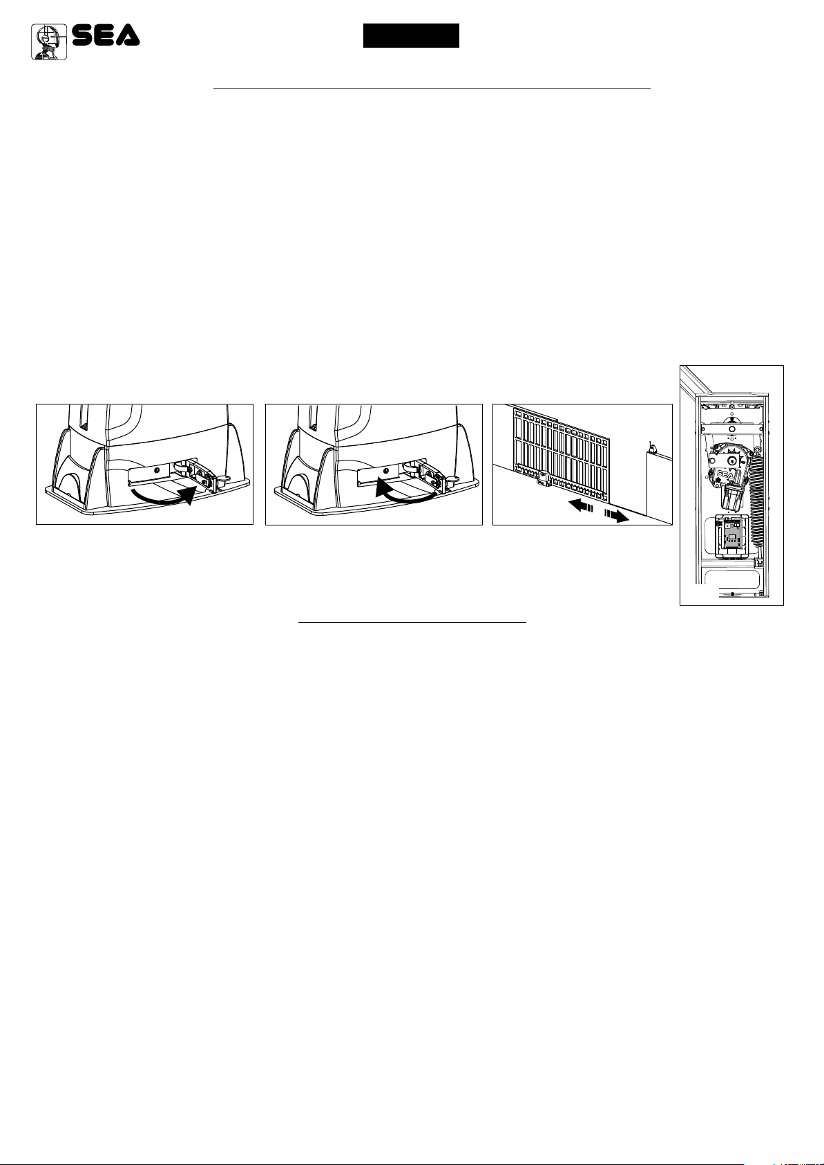
WORKING TIMES SELF LEARNING
NOTE: When using a B200 motor or magnetic limit switches in general; make sure that the control unit is set on magnetic limit switch
before learning.
MENU 34 - TYPE OF Li i T SUiT(X - AGNETI(
1) Disconnect the power supply, release the motor (Fig. 1) and put the leaves manually next to the stop in closing (Fig. 3-4).
2) Reset the mechanical lock (Fig. 2)
3) Select PROGRA ING on the display, press OK and than one of the UP or DOWN buttons. Now the gate will automatically execute a closing,
opening and reclosing cylce.
Note: If the motor starts in opening, remove and re-put power supply, select on the display REUERSE OTOR. And through the UP and DOWN
button put it on ON, or if you have the Jolly programmer, activate the motor and limit switch exchange function. If the motor starts in closing and
stops, remove the power supply and reverse the motor cables, then repeat the programming procedure.
4)The self-learning is done.
ATTENTION: This procedure is potentially dangerous and should only be performed by qualified personnel in safety conditions.
The control unit is pre-set with the default settings, to start the control unit with the DEFAULT settings just keep
pressed the UP and DOWN buttons at the same time power supplying the control unit the display shows the
message init.
The DEFAULT settings are shown in the Menues table.
UU
U U
U
Fig. 1
Fig. 2
Fig. 3
Fig.4
FUNCTION LOGIC
AUTOMATIC LOGIC
A start impulse opens the gate. A second impluse during the opening will not be accepted.
A start impulse during closing reverses the movement.
NOTE 1: To have the automatic closing it is necessary to set a pause time, otherwise all the logic will be semi-automatic.
NOTE2: It is possible to choose, whether to accept or not, the start in pause, selecting in the MENU the item Start in paVse and
choosing ON or OFF. By default, the parameter is OFF.
SECURITY LOGIC
A start impulse opens the gate. A second impulse during opening reverses the movement.
A start impulse during closing reverses the movement.
NOTE 1: To have the automatic closing it is necessary to set a pause time, otherwise all the logic will be semi-automatic.
NOTE2: It is possible to choose, whether to accept or not, the start in pause, selecting in the MENU the item Start in paVse and
choosing ON or OFF. By default, the parameter is OFF.
STEP BY STEP TYPE 1 LOGIC
The start impulse follows the OPEN-STOP-CLOSE-STOP-OPEN logic.
NOTE 1: To have the automatic closing it is necessary to set a pause time, otherwise all the logic will be semi-automatic.
NOTE2: It is possible to choose, whether to accept or not, the start in pause, selecting in the MENU the item Start in paVse and
choosing ON or OFF. By default, the parameter is OFF.
STEP BY STEP TYPE 2 LOGIC
The start impulse follows the OPEN-STOP-CLOSE -OPEN logic.
NOTE 1: To have the automatic closing it is necessary to set a pause time, otherwise all the logic will be semi-automatic.
NOTE2: It is possible to choose, whether to accept or not, the start in pause, selecting in the MENU the item Start in paVse and
choosing ON or OFF. By default, the parameter is OFF.
DEAD MAN LOGIC
The gate opens as long as the START button of opening is pressed; releasing it the gate stops. The gate closes as long as the button connected
to the PEDESTRIAN START is pressed; releasing it the gate stops. To execute complete opening and/or closing cycles the related
pushbuttons must be constantly pressed.
2 PUSHBUTTONS LOGIC
One start opens, one pedestrian start closes. In opening the closing will not be accepted. In closing a start command reopens, a pedestrian start
command (closes) will be ignored.
67411260
REV. 08 - 10/2014
23
Sistemi Elettronici
di Apertura Porte e Cancelli
International registered trademark n. 804888
®
English
USER 1 - 24V DG R1
SPECIAL MENU
PRESS AT THE SAME TIME FOR 5 SECONDS TO ENTER OR TO EXIT THE SPECIAL MENU
UPDOWN
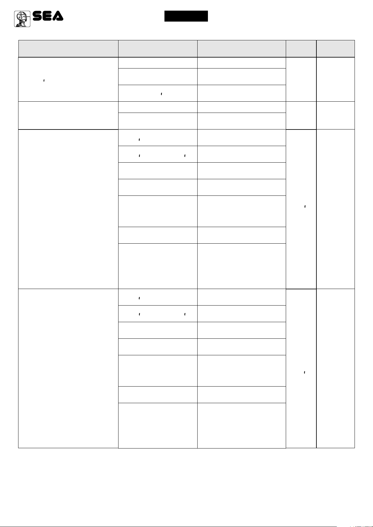
SPECIAL MENU FUNCTIONS TABLE USER 1 24V DG R1
For entering into the special menu move on one of the menu and press the
buttons at the same time for 5 s. For exiting the special menu move on one of the
menu and press the buttons at the same time for 5 s.
UP and DOWN
press END or
UP and DOWN
MENU SP
1 - speed
2 - sloudoun speed
3 - learn ng speed
4 - open ng torq
5 - (los ng torq
6 - open ng sloudoun
7 - (los ng sloudoun
8 - preflasx ng
9 - flasx ng l gxt
SET
30 100
30 100
30 100
10 100
10 100
Off
5 100
Off
5 100
Only (los ng
0.0 5.0
U
Nor al
L gxt
aluays
bvzzer
Description
Setting from 30 to 100
Setting from 30 to 100
Setting from 30 to 100
Setting from 10 to 100
Setting from 10 to 100
Disabled
Setting from 5 to 100
Disabled
Setting from 5 to 100
Pre-flashing active only
before closing
Pre-flashing time
Normal
Control lamp
Always ON
Buzzer
Default
* 80
* 40
* 80
* 70
* 70
* 30
* 30
Off
U
Nor al
Set Value
10 - (ourtesy l gxt
11 - traff ( l gxt reseruat on
12 - pedestr an open ng
13 - pedestr an PAUSE
14- a((elerat on
U
15 - a ntenan(e (y(les
U
16 - perfor ed (y(les
N (y(le
Off
1 240
Off on
20 100
= start
Off
1 240
0 100
100 10e4
0 10e4
Courtesy light in cycle
Disabled
Courtesy light setting
from 1s to 4min.
When setting this function
the pedestrian input will be
activated to work on the
auxiliary board SEM
(traffic light management).
Setting from 20 to 100
Pause in pedestrian
opening same as in
total opening
Disabled
Setting from 1s to 4 min.
Acceleration ramp
Setting from 100 to
100000
Reports the executed
cycles. Keep pressed OK
to reset the cycles
N (y(le
Off
30
= start
* 70
10e4
0
24
67411260
REV. 08 - 10/2014
Sistemi Elettronici
di Apertura Porte e Cancelli
International registered trademark n. 804888
®
English
USER 1 - 24V DG R1
MENU SP
U
17 - t er
18 - edge
19 - PXOTO1
SET
off
ON PXOTO2
ON PEDESTR AN ENTRY
U
Nor al
8x2
(LOS NG
OPEN NG AND (LOS NG
stop
Stop AND (LOSE
(LOSE
PAUSE RELOAD
u
Delay pause ti e
Description
Disabled
Timer function active
on photocell 2
Timer function active on
pedestrian input
Normal N.C. contact
Edge is active and
protected by a 8k2 resistor
Photocell active in closing
Photocell active in opening
and closing
Photocell active before
opening
The photocell stops in closing
and closes when released
The photocell gives a
command to close during
opening, pause and
closing
The photocell charging the
pausing time
If the photocell is occupied
during opening, pause or
closing, the gate reopens
completely and closes
without observing the
pause time.
Default
off
U
Nor al
(LOS NG
Set Value
20 - PXOTO2
(LOS NG
OPEN NG AND (LOS NG
stop
Stop AND (LOSE
(LOSE
PAUSE RELOAD
u
Delay pause ti e
Photocell active in closing
Photocell active in opening
and closing
Photocell active before
opening
The photocell stops in closing
and closes when released
The photocell gives a
command to close during
opening, pause and
closing
The photocell charging the
pausing time
If the photocell is occupied
during opening, pause or
closing, the gate reopens
completely and closes
without observing the
pause time.
OPEN NG
67411260
REV. 08 - 10/2014
25
 Loading...