

SEA USER 1 - 24V DG MAXI User Manual
®
Sistemi Elettronici
di Apertura Porte e Cancelli
International registered trademark n. 804888
Italiano
English
Français
USER 1 - 24V DG MAXI
Español
23024074
APPAR. ELETTRONICA 24V PER CANCELLI SCORREVOLI E BARRIERA
24V ELECTRONIC CONTROL UNIT FOR SLIDING GATES AND BARRIERS
ARMOIRE ELECTRONIQUE 24V POUR PORTAILS COULISSANTS ET BARRIERES
DISPOSITIVO ELECTRÓNICO 24V PARA CANCELAS CORREDIZOS Y BARRERAS
67411261
SEA S.p.A.
Zona Ind.le S. Atto - 64020 S. Nicolò a Tordino (TE)
Tel. 0861.588341 - Fax 0861.588344
www.seateam.com
e-mail: seacom@seateam.com
REV. 01 - 07/2016
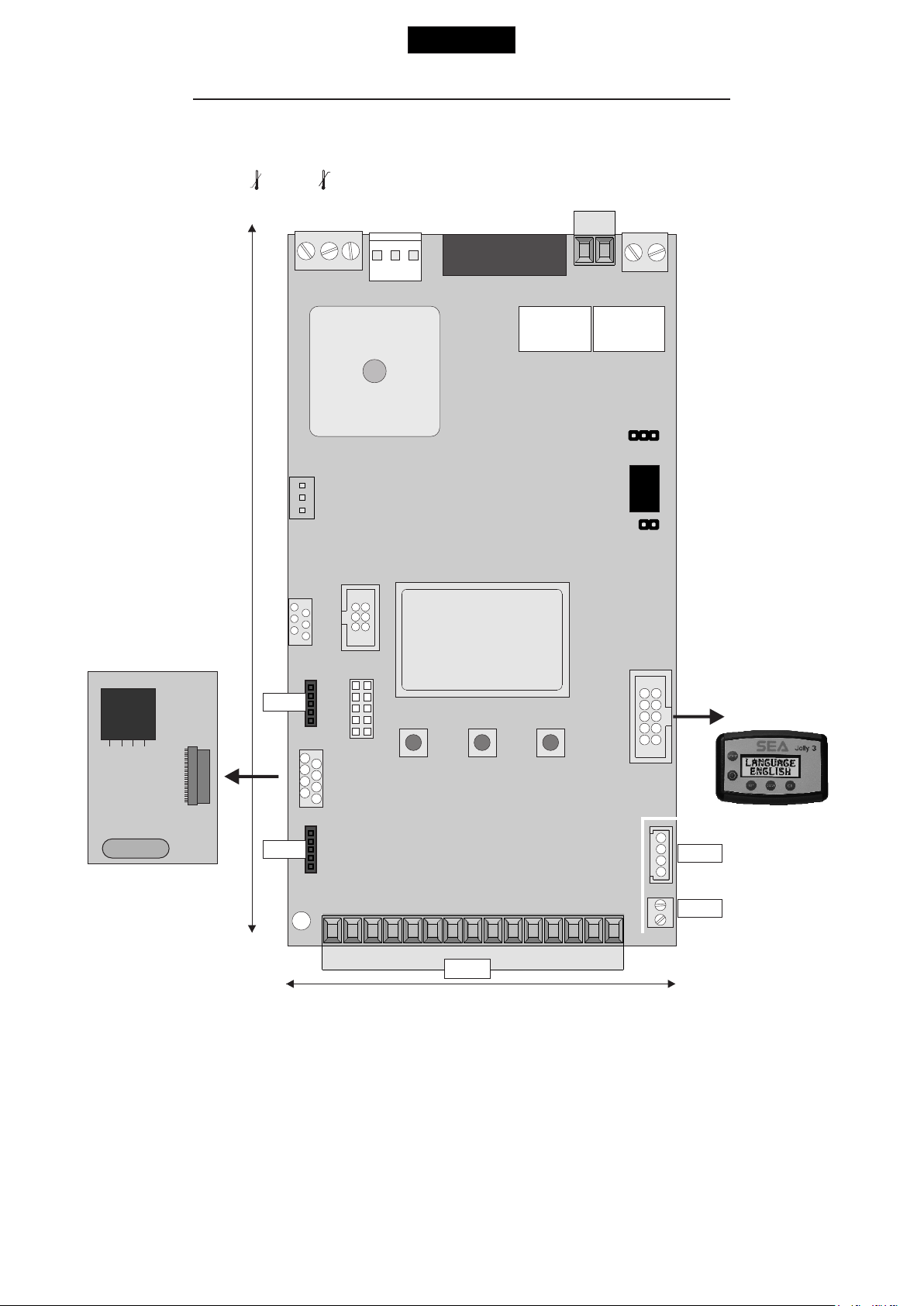
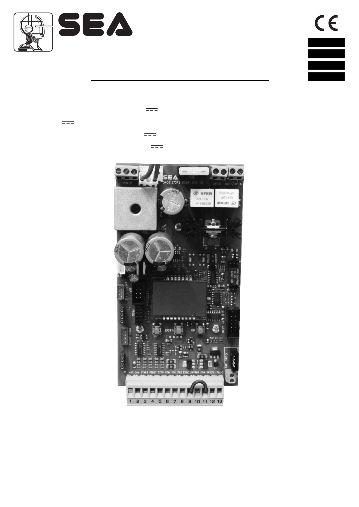
DESCRIPTION OF THE COMPONENTS
TECHNICAL SPECIFICATIONS
Control unit power supply: 24 V~
Absorption in stand by: 30 mA
Maximum motor current: 20A
Environment temperature: -20°C +50°C
Specifications of external enclosure: 305 x 225 x 125 mm - Ip55
CN8
CN7
English
F1
USER 1 - 24V DG MAXI
CN6
CN5
RX RECEIVER
CNE
1
CN4
156 mm
CNS
POWER
ENCODER
MASTER/SLAVE
PROG
CNA
RADIO MODULE
PR1
EXP
CNP
- S +
UP
FUSE
DISPLAY
DOWN
RL1
OK
MOTOR
LIGHT
RL2
JOLLY
JP2
RL3
JP1
CN9
JOLLY3
22
CNS
CN1 = Input/Output connector
CN2 = Pre-wired limit switch connector
CN3 = Not Pre-wired limit switch connector
CN4 connector= Master/slave
CN5 = Courtesy light output connector
CN6 otors connector= M
CN7 = Batteries connector - Quick connection
CN8 = Power connector
Cn9 = Jolly 3 connector
CNA = RX Receiver connector
CNE = Encoder connector
CNP = Programming connector
CN2
LIMIT SWITCH
CN3
CN1
100 mm
CNS = RF FIX receiver connector
EXP = External module connector
OK = Programming button
DOWN = Programming button
UP = Programming button
RL1 = Motors control relay
Rl2 = Motors control relay
RL3 = Light/dry output contact relay
PR1 = Rectifier bridge
F1 = Fuse 20 AT
Jp1 = Relay 3 activation
JP2 = Light/dry contact selection
English
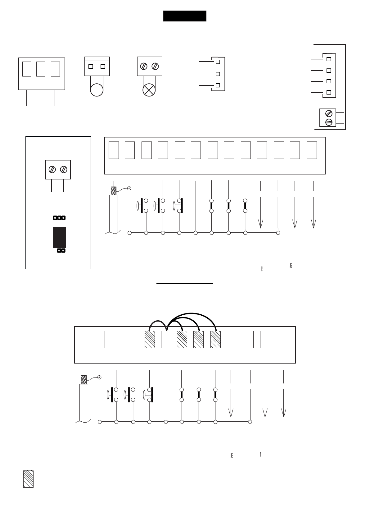
CONNECTIONS
USER 1 - 24V DG MAXI
POWER (CN8)
24V~
LIGHT (CN5)
Light/Dry contact
JP2
RL3
MOTOR (CN6)
M
Max 400W
1
ANT COM START
LIGHT (CN5)
Max 100mA
2
3 4
Brown
White
Green
5 6
PEDST
STOP COM PH1 PH2
1
CN1
7 8
ENCODER (CNE)
Limit switch Cl.1 (Yellow)
Limit switch Op.1 (Green)
Common (White)
Limit switch Cl.1 (Yellow)
Limit switch Op.1 (Green)
9
10
11
EDGE
AUX
COM 24V (FL)-
- -
+ +
24V (Red)
12
13
CN2
LIMIT SWITCH
1
CN3
START Ped.
Stop
Common
Photocell 1
Photocell 2
Safety edge
Common
AUX Programmable
(24V 300 mA max)
24V 750 mA max
Flash (-)
(Accessori)
Start
JP1
Antenna
Common
JUMPERS
WARNING: The control unit is designed with the automatic detection of not used N.C. inputs (photocells, Stop and Limit switch) except the
SAFETY EDGE input. The exclude inputs in self-programming can be restored in the “Check inputs” menu without need to repeat the
programming (pag.33).
CN1
2
1
ANT COM START
3 4
5 6
PEDST
STOP COM PH1 PH2
7 8
9
EDGE
10
11
AUX
COM 24V (FL)-
+ +
- -
12
13
Optional
Antenna
Start
Common
START Ped.
Stop
Common
Photocell 1
Photocell 2
Safety edge
Common
AUX Programmable
(24V 300 mA max)
24V 750 mA max
The herein reported functions
are available starting from
revision 01.21 compatible only
with Jolly 3.
Flash (-)
(Accessori)
23
English
USER 1 - 24V DG MAXI
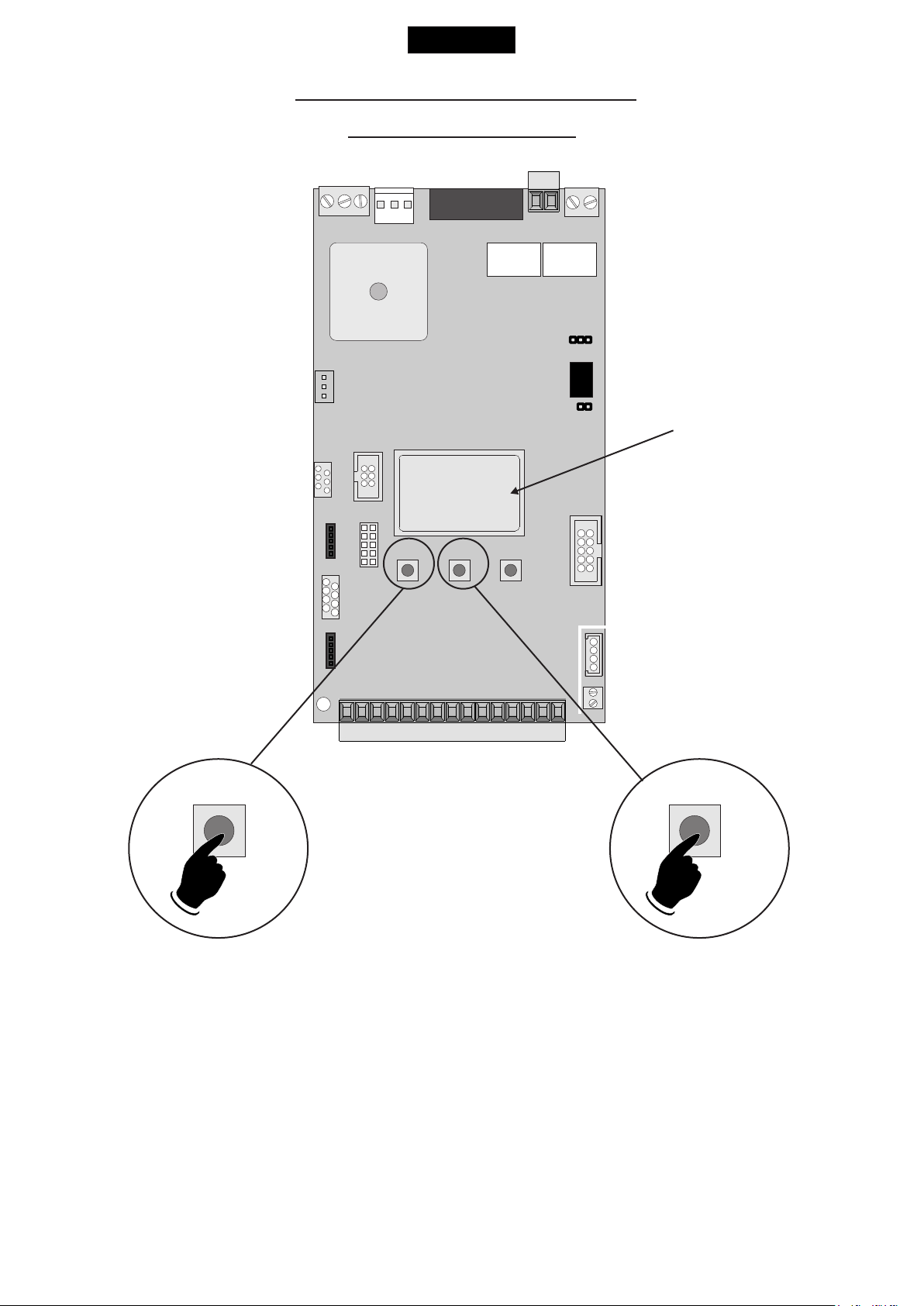
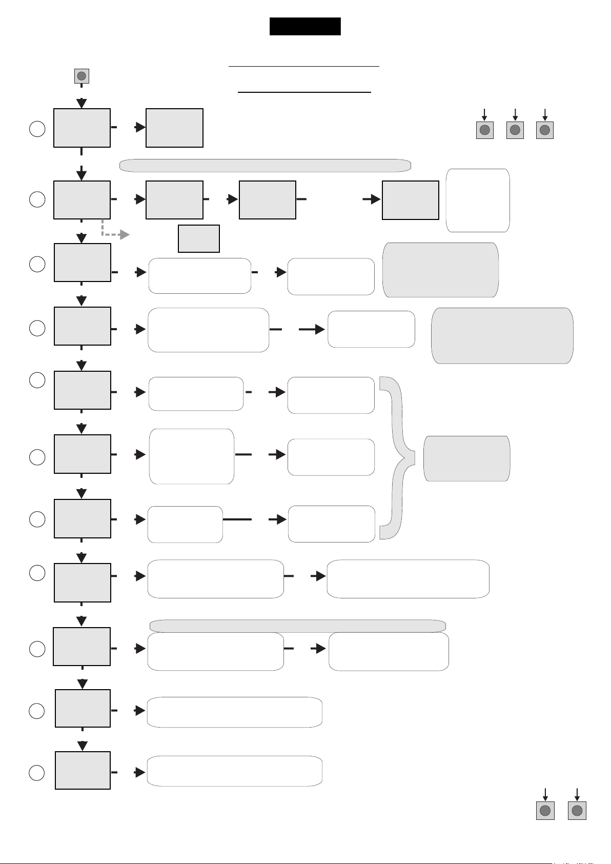
QUICK SELF-EARNING
PROGRAMMING
DISPLAY
“Input check
---
--
---
UP DOWN
UP DOWN
menu"
5 s 5 s
Start quick programming
You can start the quick programming by
holding UP for 5 s in the “Input check
menu", until the motor starts.
24
Fast self-learning START command by
radio control
You can store the START button of the
remote control while pressing DOWN for 5 s
in the “Input check menu".
Once the writing "Press button" appears,
press the button of the transmitter, which
you want to store for the START command.
By pressing OK, you can exit the menu,
otherwise it will be left automatically after 5
seconds.
English
PROGRAMMING
USER 1 - 24V DG MAXI
MENU
1
LANGUAGE
MENU
2
TRANSMITTERS
MENU
3
MENU
REVERSE
5
MENU
6
(See
page 26)
UP
SEA
UP
SEA
UP
SEA
MOTOR
UP
SEA
MOTOR
UP
SEA
LOGIC
UP
SET
OK
SEA
MENU
ITALIANO
SET
Skip this step if you do not want to program a transmitter
SET
OK
If on the display
appears the item:
SET
SET
OK
SET
OK OK
SEA
MENU
START
MENU
SET
SEA
RECEIVER
MISSING
OK
SET
Choose the type of
motor with
UP or DOWN
Choose "ON" with UP or
DOWN button only if in
programming the motor starts
in opening
With UP or DOWN
choose
the desired logic
QUICK START
SEA
MENU
PRESS
BUTTON
Check if a receiver has
been connceted
(see page 22)
OKOK
SET
OK
Press the
button of the
TX to be
stored
To confirm and return
to main menu
To confirm and return
To confirm and return
to main menu
MENU
104 - SELECT LIMIT SWITCH
to main menu
PROGRAMMING
SEA
SET
STORED
If the motor has
magnetic limit switches,
select "Magnetic"
in the special menu:
OK to exit
Menu or press
the button of
the next TX to
be stored
Return to the
9-PROGRAMMING menu,
put the gate halfway and
repeat the times programming.
BUTTONS
DOWNUP
OK
7
8
9
(See
page 26)
10
15
SEA
MENU
SET
PAUSE TIME
UP
SEA
MENU
SET
START IN
PAUSE
UP
SEA
MENU
SET
PROGRAM-
MING
UP
SEA
MENU
SET
TEST START
UP
SEA
MENU
SET
END
OK OK
choose a delay for
With UP or DOWN
To confirm and return
automatic closing
With UP or DOWN
OK OK
To confirm and return
Choose ON
OK OK
With UP or DOWN choose ON
to start times learning
The gate will execute a CLOSING-OPENING-CLOSING CYCLE
Skip this step if a TX has already been stored
OK OK
UP or DOWN Choose
OK
With
ON to start test
Press OK to return to the
display of the inputs state.
to main menu
to main menu
the control unit returns automatically
To confirm and return to
Skip this step
if you wna tto work
in half-automatic
logic
At the end of the selflearning
to the main menu
main menu
UP
SEA
16
MENU
SPECIAL
MENU
SET
OK
Press OK to enter the special menu.
ALL OTHER PARAMETERS HAVE DEFAULT SETTINGS WHICH ARE USEFUL FOR THE 90% OF THE APPLICATIONS
BUT CAN BE HOWEVER SET THROUGH THE SPECIAL MENU. FOR ENTERING INTO THE SPECIAL MENU MOVE
ON ONE OF THE MENU AND PRESS THE UP AND DOWN BUTTONS AT THE SAME TIME FOR 5 S.
UPDOWN
25
English
USER 1 - 24V DG MAXI
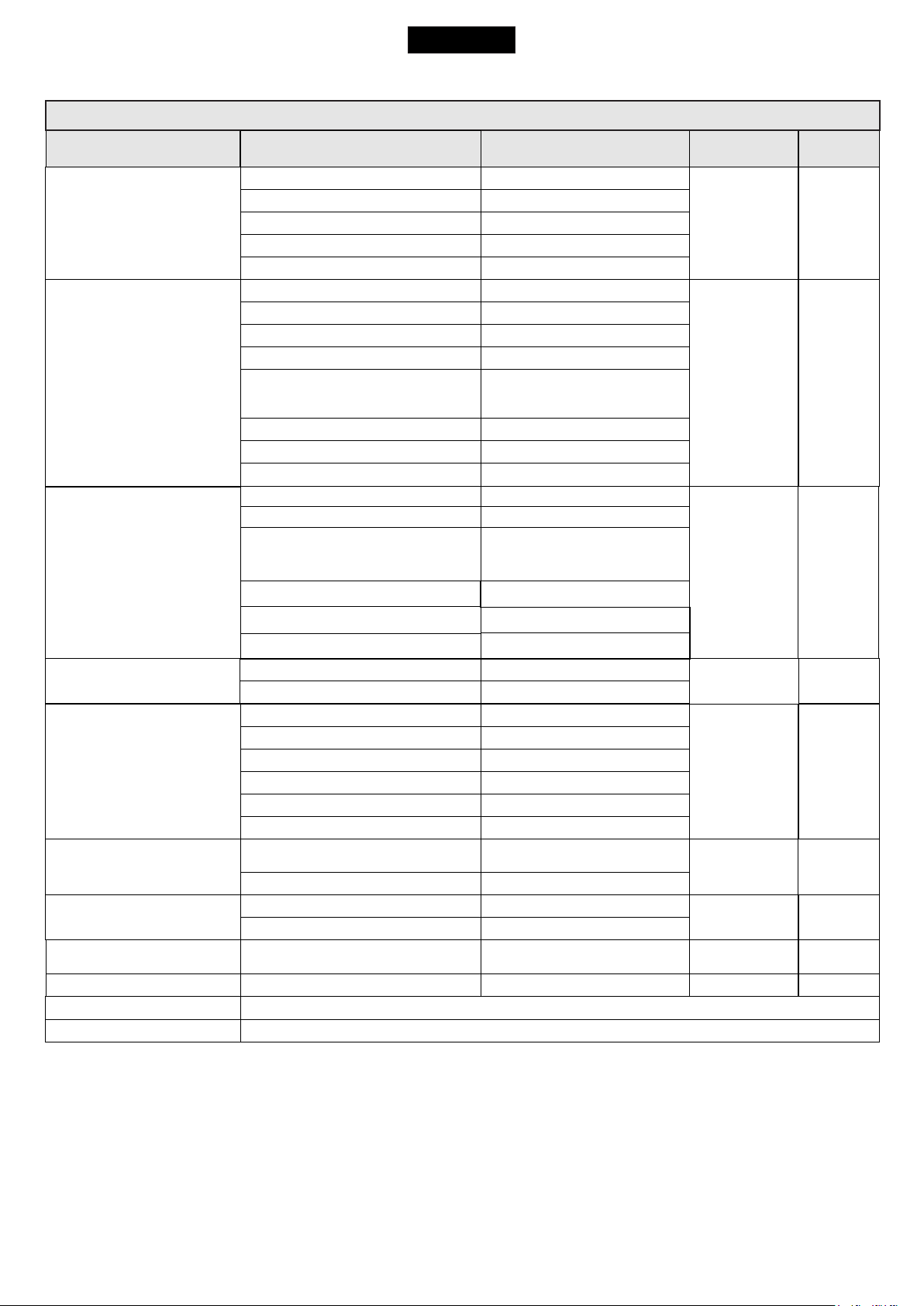
MENU FUNCTIONS TABLE USER1 24V DG MAXI
MENU
1 - LANGUAGE
2 - TRANSMITTERS
3 - MOTOR
5 - REVERSE MOTOR
6 - LOGIC
(See page 27)
7 - PAUSE TIME
8 - START IN PAUSE
9 - PROGRAMMING
(See page 27)
10 - TEST START
15 - END
16 - SPECIAL MENU
SET
Italiano
English
Français
Español
Dutch
Start
Pedestrian Start
External module
Stop
Unloch
Delete A TX
Clear memory
End
Saturn Fast - Saturn Super Fast
Joint
Centralina idraulica
Lepus box chain
Slim Slim
Saturn 1500 - Lepus 2000
Off
On
Automatic
Open-stop-close-stop-open
Open-stop-close-open
2 buttons
Safety
Dead man
Off
1 240
Off
On
Off On
Off On
Press OK to return to the display of the firmware version and to the one of inputs state.
Press OK to enter the special menu.
Italian
English
French
Spanish
Olandese
Start
Pedestrian Start
External module
Stop
Storing of a command for
unlocking an electric brake
Delete single transmitter
Delete transmitter memory
“Transmitters” menu output
Saturn Fast - Saturn Super Fast
Joint
Hydraulic unit
Please note:
currently not available
Lepus box chain
Saturn 1500 - Lepus 2000
Synchronized right motor
Synchronized left motor
Automatic
Step by step type 1
Step by step type 2
Two buttons
Safety
Dead man
OFF
(semi-automatic logics)
Setting from 1s to 4min.
In pause start is not acceped
In pause start is accepted
Times learning start
Start command
Description
Default
Italiano
Start
Pedestrian
Start
Saturn fast-
Saturn
super fast
Off
Open-stopclose-open
Off
Off
Off
Off
Set value
26
English
USER 1 - 24V DG MAXI
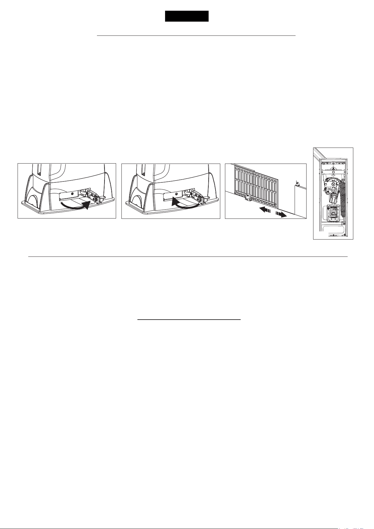
WORKING TIMES SELF LEARNING
NOTE: When using a magnetic limit switches in general; make sure that the control unit is set on magnetic limit switch before
learning.
MENU 104 - SELECT LIMIT SWITCH - “Magnetic”
1) Disconnect the power supply, release the motor (Fig. 1) and manually position the leaves or the beam on halfway (Fig. 3-4).
2) Reset the mechanical lock (Fig. 2)
3) Select 9 - PROGRAMMING on the display, press OK and than one of the UP or DOWN buttons. Now the gate will automatically execute a
closing, opening and reclosing cylce.
Note: If the motor starts in opening, remove and re-put power supply, select on the display 5 - REVERSE MOTOR. And through the UP and
DOWN button put it on ON, or if you have the Jolly 3 programmer, activate the motor and limit switch exchange function. If the motor starts in
closing and stops, remove the power supply and reverse the motor cables, then repeat the programming procedure.
4)The self-learning is done.
ATTENTION: This procedure is potentially dangerous and should only be performed by qualified personnel in safety conditions.
The control unit is pre-set with the default settings, to start the control unit with the DEFAULT settings just keep
pressed the UP and DOWN buttons at the same time power supplying the control unit the display shows the
message “Init”.
The DEFAULT settings are shown in the Menues table.
Fig. 1
Fig. 2
Fig. 3
Fig.4
PROGRAMMING SLIM MOTOR WITHOUT LIMIT SWITCH
The SLIM motor has no limit switches and works only with Encoder. For the stroke learning it is necessary that the motor reaches the
mechanical stops. Learning provides a CLOSE-OPEN-CLOSE cycle with automatic detection of the mechanical stops. During normal cycle
the motor will stop at about 1 cm from the mechanical stop. This space will be regulated through the motor release parameter (meu 82).
Attention:
In case of the STOP command, power failure or obstacle detection, the motor will perform a closing maneuver at low speed up to the
mechanical stop in closing, to retrieve the position.
FUNCTION LOGIC
AUTOMATIC LOGIC
A start impulse opens the gate. A second impluse during the opening will not be accepted.
A start impulse during closing reverses the movement.
SECURITY LOGIC
A start impulse opens the gate. A second impulse during opening reverses the movement.
A start impulse during closing reverses the movement.
STEP BY STEP TYPE 1 LOGIC
The start impulse follows the OPEN-STOP-CLOSE-STOP-OPEN logic.
STEP BY STEP TYPE 2 LOGIC
The start impulse follows the OPEN-STOP-CLOSE -OPEN logic.
NOTE1 : To have the automatic closing in this logic it is necessary to set a pause time , otherwise all the logics will be
semi-automatic
NOTE2: It is possible to choose whether to accept or not the start in pause, by selecting in the MENU point 8-START IN
PAUSE and choosing ON or OFF. The default parameter is OFF.
DEAD MAN LOGIC
The gate opens as long as the START button of opening is pressed; releasing it the gate stops. The gate closes as long as the
button connected to the PEDESTRIAN START is pressed; releasing it the gate stops. To execute complete opening and/or
closing cycles the related pushbuttons must be constantly pressed.
2 PUSH BUTTONS LOGIC
One start opens, one pedestrian start closes. In opening the closing will not be accepted. In closing a start command reopens, a
pedestrian start command (closes) will be ignored.
27
English
USER 1 - 24V DG MAXI
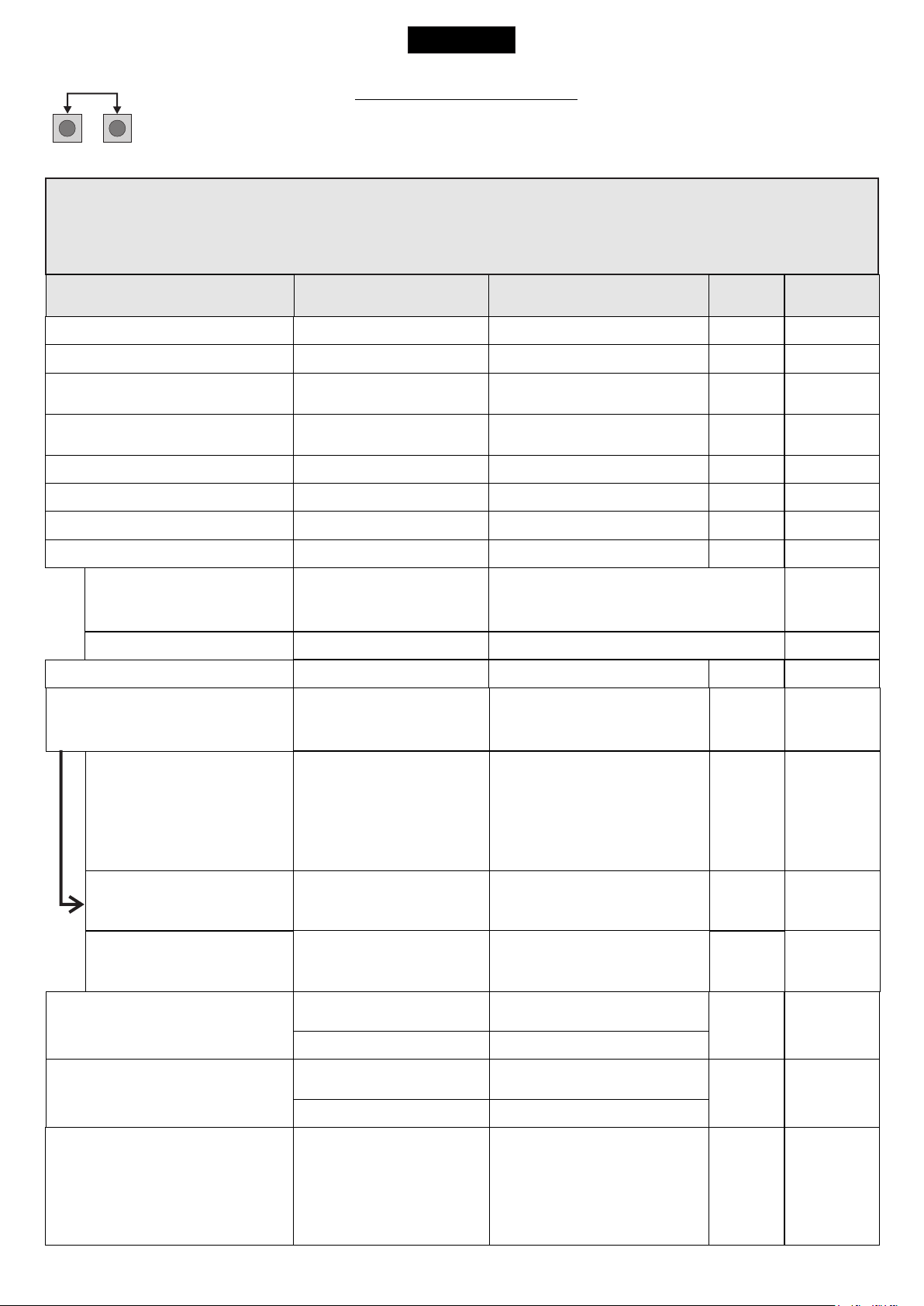
SPECIAL MENU
PRESS AT THE SAME TIME FOR 5 SECONDS TO ENTER OR TO EXIT THE SPECIAL MENU
UPDOWN
SPECIAL MENU FUNCTIONS TABLE USER 1 24V DG MAXI
For entering into the special menu move on one of the menu and press the UP and DOWN
buttons at the same time for 5 s. For exiting the special menu press END or move on one of the
menu and press the UP and DOWN buttons at the same time for 5 s.
MENU SP
17 - OPENING SPEED 1 *
18 - CLOSING SPEED 1 *
21 - OPENING SLOWDOWN
SPEED 1 *
22 - CLOSING SLOWDOWN
SPEED 1 *
25 - LEARNING SPEED *
28 - OPENING TORQ 1 *
29 - CLOSING TORQ 1 *
32 - ENCODER *
47 - ENCODER PAR. *
48 - ENCODER TOT. *
32 - ENCODER *
32 - ENCODER *
51 - I.PAR.M1 *
52 - I.AP.M1 *
53 - I.CH.M1 *
33 - OPENING SENSITIVITY
MOTOR1 *
34 - CLOSING SENSITIVITY
MOTOR1 *
57 - WORKING CURRENT
SET
30 100
30 100
30 100
30 100
30 100
10 100
10 100
On
xxx.
xxx.
Off
Potentiometer
- - - - - - - -
- - - - - - - -
- - - - - - - -
10% (Fast intervention)
99% (Slow intervention)
Off (Intervention excluded)
10% (Fast intervention)
99% (Slow intervention)
Off (Intervention excluded)
- - - - -
Description
Setting from 30 to 100
Setting from 30 to 100
Setting from 30 to 100
Setting from 30 to 100
Setting from 30 to 100
100% Maximum torque
10% Minimum torque
In ON enables the Encoder
Encoder impulses during operation.
This parameter is useful for seeing if the
Encoder is working correctly.
Encoder impulses stored in programming
In OFF disabled the Encoder
Enables the reading of
the potentiometer with
LE card.
Reports the current position
of the potentiometer on the
leaf.
This parameter is useful for
seeing if the potentiometer
is read correctly.
Reports the impulses
stored by the control unit
when the leaf is fully open.
Reports the impulses stored
by the control unit when the
leaf is fully close.
Adjusts the intervention time
of the Encoder in opening
Disabled
Adjusts the intervention time
of the Encoder in closing
Disabled
Shows the absorbed current
by the motor during the
movement. The letter H at the
left of the current value
indicates the exceeding of the
set inversion threshold.
Default
* 70
* 70
* 40
* 40
* 75
* 70
* 70
ON
Off
Off
35
35
Set Value
Note: Menus 47 and 48 are only present if the encoder is ON.
28
English
USER 1 - 24V DG MAXI
MENU SP
59 - OPENING
SLOWDOWN 1 *
60 - CLOSING
SLOWDOWN 1 *
63 - DECELERATION
64 - ACCELERATION *
70 - OPENING POSITION
RECOVERY
71 - CLOSING POSITION
RECOVERY
72 - OPENING TOLERANCE
MOTOR1
73 - CLOSING TOLERANCE
MOTOR1
79 - ANTI INTRUSION
SET
Off
5 100
Off
5 100
Off
100%
0 %
100%
0 15
0 15
0 100
0 100
Only opening
Only closing
Opening and closing
Off
Description
Disabled
Setting from 5 to 100
Disabled
Setting from 5 to 100
Adjust the passage
between normal speed
and slowdown speed
Acceleration ramp.
Adjusts the motor start.
Retrieves the inertia of the
motor in opening after Stop
or reversing
Retrieves the inertia of the
motor in closing after Stop
or reversing
Adjust the tolerance between
stop and obstacle opening
Adjust the tolerance between
stop and obstacle closing
If you force the gate
manually, the control
unit starts the motor to
restore the state of the
gate before forcing.
Default
* 30
* 30
10%
* 70%
6 %
6 %
0
0
Off
Set Value
82 - MOTOR RELEASE
85 - PREFLASHING
86 - FLASHING LIGHT
87 - FLASHING LIGHT
AND TIMER
Off
1 100
Only closing
0.0 5.0
Normal
Light
Always
Buzzer
Off
On
Disabled
Setting from 1 to 100
Pre-flashing only
active before closing
Pre-flashing time
Normal
Control lamp
Always ON
Buzzer
The flashing light remains
OFF with the active timer
and open gate
The flashing light remains
ON with active timer and
open gate
Off
0.0
Normal
Off
29
 Loading...