

®
Sistemi Elettronici
di Apertura Porte e Cancelli
International registered trademark n. 804888
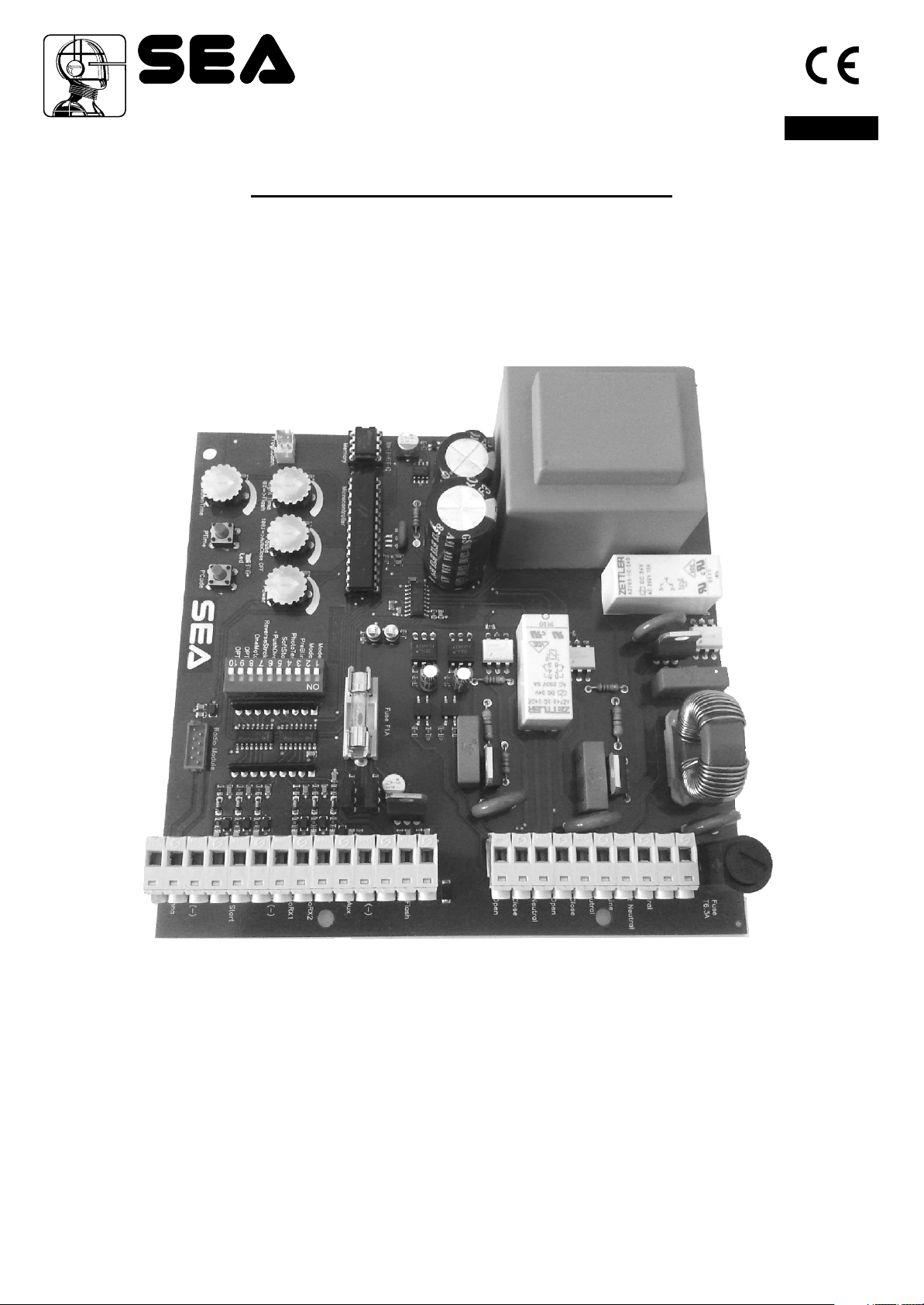
SWING 2 AMP
ELECTRONIC CONTROL UNIT FOR SWING GATES
English
23021093/23021094
67410672
SEA S.r.l.
Zona industriale 64020 S.ATTO Teramo - (ITALY)
Tel. +39 0861 588341 r.a. Fax +39 0861 588344
www.seateam.com
seacom@seateam.com
REV 00 - 06/2012

®
Sistemi Elettronici
di Apertura Porte e Cancelli
International registered trademark n. 804888
English
Italiano
SWING 2 AMP
INDEX
COMPONENTS DECRIPTION .....................................................................................................3
CONNECTIONS............................................................................................................................4
GENERAL INFORMATION ..........................................................................................................5
FUNCTION LOGICS SETTING (DIP-SWITCH)............................................................................6
ADDITIONAL FUNCTIONS (DIP-SWITCH)..................................................................................7
TRIMMER ADJUSTMENT ............................................................................................................8
ALARMS INDICATIONS TABLE....................................................................................................8
PALM FUNCTIONS.......................................................................................................................8
START, STOP, PEDESTRIAN START, ANTENNA, PHOTOCELLS, ELECTRIC LOCK, WARNING
LAMP, EDGE CONNECTIONS ....................................................................................................9
POWER SUPPLY AND MOTOR CONNECTIONS......................................................................10
AMPEROMETRIC MANAGEMENT ACTIVATION.......................................................................11
WORKING TIMES SELFLEARNING ON SWING GATE ............................................................12
SINGLE LEAF MODE .................................................................................................................14
RADIO TRANSMITTERS MEMORIZING....................................................................................15
RADIO TRANSMITTERS CANCELLATION................................................................................15
SAFETY LOOP CONNECTION ..................................................................................................16
TROUBLE SHOOTING ...............................................................................................................17
WARNINGS AND GUARANTEE.................................................................................................17
2
67410672 REV 00 - 06/2012
Sistemi Elettronici
di Apertura Porte e Cancelli
International registered trademark n. 804888
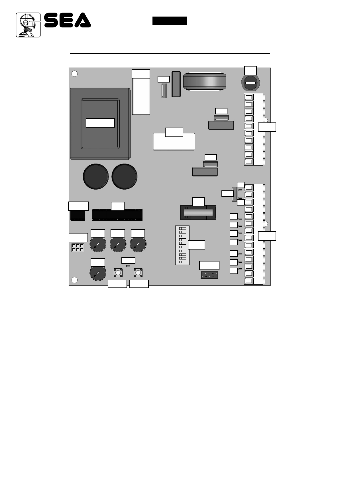
COMPONENTS DESCRIPTION
®
English
Italiano
SWING 2 AMP
MEM
CNP
TRASF
Rv4
µP
Rv2 Rv1Rv3
LEDP
RL1
TR1
RL2
1
2
3
4
5
6
7
8
9
10
F2
DIP
TR3
CMR
TR2
TR4
L7
L6
L5
L4
L3
L2
L1
F1
CN2
L9
L8
CN1
CN1 =
CN2 =
CMR =
CNP=
Ptime
24 V input/output connector
Motors and power supply connector
Radio Receiver connector
Connector PALM
PCode
L1 = Start
Pedestrian Start
L2 =
L3 = Stop
Photocell 1
L4 =
Photocell 2
L5 =
L6 = Safety edge
L7 = 24V Aux
L8 = 24V Flash
Electro-lock
L9 =
LEDP =
F1 =
F2 = 1A
Programming
Power supply and motor 6.3AT fuse
Accessories Fuse
67410672 REV 00 - 06/2012
Rv1 = Motor torque adjustment
Rv2 = Pause time adjustment
Rv3 = Courtesy light or flashing lamp delay adjustment
Rv4 = Slowdown times adjustment
PTime = Working times learning push-button
Pcode = Radio transmitters learning push-button
DIP = Function Dip-switch setting
RL1 = Motor power supply relay
RL2 = Motor direction relay
µP = Microprocessor
MEM = Memory
TRASF = Transformer
TR1 = Triac courtesy light
TR2 = Triac motor 1piloting
TR3 = Triac motor 2 piloting
TR4 = Tip 127 electro-lock piloting
3
®
SWING 2 AMP
Sistemi Elettronici
di Apertura Porte e Cancelli
International registered trademark n. 804888
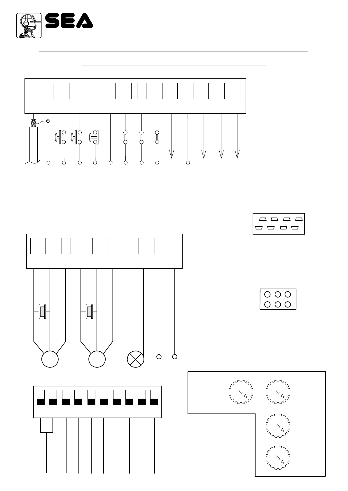
CONNESSIONI / CONNECTIONS / CONNEXIONS
CONEXIONES / VERBINDUNGEN
CN1
2
1
Antenne
Antenne / Antena
Antenna / Antenna
3 4
Start
Gemeinsam
Comun / Común
Comune / Common
5 6
Stop
START Fuss.
Comune / Common
START Ped./ START Ped.
START Piéton / START Peat.
Comun / Común
Gemeinsam
7 8
Lichtschranke 1
Fotocellula 1/ Photocell 1
Photocellule 1 / Fotocélula 1
9
10
24V Aux
Lichtschranke 2
Fotocellula 2/ Photocell 2
Costa / Edge / Tranche /
Photocellule 2 / Fotocélula 2
(300 mA max)
Sicherheitsleiste
Banda de seguridad /
11
Comun / Común
Comune / Common
Gemeinsam
12
24V
13
14
Lock
(300 mA max)
(300 mA max)
24V (Blinklampe)
24V (Lamp.) / 24V (Flash)
RADIO MODULE (CNA)
24V (Lampe) / 24V (Lámpara)
CN2
Connettore modulo ricevente
Receiver module connector
Connecteur module récepteur
Conector modulo receptor
1
2
3 4
5 6
7 8
9
10
Verbindungsmodul Empfänger
Neutro
M2 Open
M2 Aperto
M2 Close
M2 Neutro
M2 Chiuso
Capacitor
Condensatore
M2
M1 Open
M1 Aperto
M2 Neutral
M1 Close
M1 Neutro
M1 Chiuso
Capacitor
Condensatore
M1 Neutral
Courtesy light (Line)
Luce di cotesia (Linea)
Luce di cortesia (Neutro)
M1
Neutral
Courtesy light (Neutral)
Connettore Programmatore PALM COPY
Connector programmer PALM
Connecteur programmer PALM
Conector Programador COPY
Anschluss Programmierer COPY
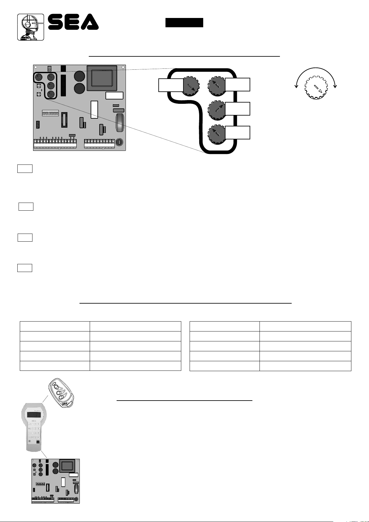
REGOLAZIONE TRIMMER
CNP
COPY
COPY
PALM
PALM
Line
Linea
TRIMMER ADJUSTMENT
DIP
2
1
Mode1
Logic selection
Selezione logiche
4
4
67410672
Mode2
3 4
Pre-blink
Pre lampeggio
5 6
Soft stop
Photo test
Rallentamento
Autotest fotocell.
7 8
Push Over
Serraggio anta
Reverse stroke
Colpo d’inversione
9 10
One motor
Singola anta
Edge/Timer
Costa / Timer
Richiusura con fotocell.
Reclosing with photocell
REV 00 - 06/2012
Tempo di
rallentamento
Slow down time
Rv4 Rv3
Rv2
Rv1
Tempo luce
di cortesia
Light time
Tempo di pausa e
richiusura
automatica
Pause -
autotest close
Coppia motore
Power
®
Sistemi Elettronici
di Apertura Porte e Cancelli
International registered trademark n. 804888
English
Italiano
SWING 2 AMP
GENERAL INFORMATION
GENERAL FEATURES
SWING 2 AMP control unit has been deigned in order to manage one or two swing operators without limit
switch. Its dimensions are very small, four different operation modes, possibility to adjust many
parameters using the trimmer and dip switch, as well as the possibility of having the inversion without
additional devices on electromechanical motors.
TECHNICAL FEATURES
Control unit power supply
Transformer 230V / 115V
Absorbed power
Max. motor charge
Max. accessories charge
Max. charge flashing lamp or
Courtesy light
Max. flashing light charge 24V
Environment temperature
Protection fuses (24V accessories)
Programming modes
Operating logics
Opening / closing time
Pause time
Courtesy light delay
Thrust force
Slowdowns
Leaf delay
230V ~ (±10%) - 50/60 Hz / 115V~ (±10%) 50/60 Hz
P1: Vn=230V~, Io=43.3 mA; S1: Vnom=17.5V~, Vo=20.2V~, I=0.69A
P1: Vn=115V~, Io=43.3 mA; S1: Vnom=17.5V~, Vo=20.2V~, I=0.69A
7,5 W
500 W x 2
24V 300mA
230V~ 50W max.
24V 4V Led
-20°C +50°C
1 A
Selflearning page 12
Automatic / Safety / St.by St.1 / St. by St. 2 / Dead man /
2 Butons
Adjsutable in autoprogramming
Adjustable with trimmer from 0 to 120 s
Adjustable with trimmer from 0 to 2 min.
Adjustable with trimmer
Adjustable with trimmer
In selflearning
Amperometric sensitivity
Connecting terminal entries
Connecting terminal exits
Board dimensions
Outside box features
67410672 REV 00 - 06/2012
Adjustable with PTime and PCode
Antenna / Stop / Start / Pedestrian Start /
Photocells 1 and 2 / Edge
Power supply accessories 24V / Motors 230V 500W x 2 /
Flashing lamp or courtesy light 230V 50W / Electro-lock12V
15VA max/ TX photocell power supply 24V / Capacitors
150,7 x 141 x 47,5 mm
305 x 225 x 125 mm - IP55
5
®
Sistemi Elettronici
di Apertura Porte e Cancelli
International registered trademark n. 804888
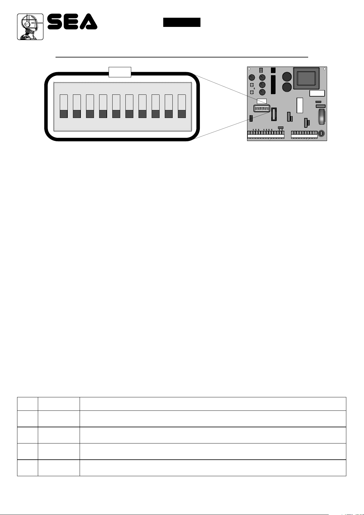
OPERATING LOGICS (DIP-SWITCH)
DIP
ON
1 2 3 4 5 6 7 8 9 10
WORKING LOGICS
Four different working logics can be selected.
The programming takes place using DIP1 and DIP2.
English
Italiano
SWING 2 AMP
DIP
- MANUAL LOGIC
A START command opens the gate. A second START while it is opening stops the motor.
A START command while it is closing stops the motor.
Important note: To obtain the semi-automatic reclosing turn the trimmer Rv2 completely clockwise.
- SAFETY LOGIC
A START command opens the gate. A second START while it is opening reverses the motor, a start closes
the gate.
A START command while it is closing reverses the motor.
Important note: To obtain the semi-automatic reclosing turn the trimmer Rv2 completely clockwise.
- AUTOMATIC LOGIC 1 (with automatic closing)
A START command opens the gate. A second START while it is opening is not accepted. A START while in
pause is not accepted, at the end of the pause the automation closes, a START while it’s closing reverses
the motor.
Important note: To obtain the semi-automatic reclosing turn the trimmer Rv2 completely clockwise.
- AUTOMATIC LOGIC 2
A START command opens the gate. A second START while it is opening is not accepted. A START during
the pause time closes the gate immediately. A START while it is closing reverses the direction.
Important note: To obtain the semi-automatic reclosing turn the trimmer Rv2 completely clockwise.
DIP
1 / 2
1 / 2
1 / 2
1 / 2
6
OPENED
CLOSED
OFF / OFF
ON / OFF
OFF / ON
ON / ON
67410672 REV 00 - 06/2012
DIP1 AND DIP2 PROGRAMMING FOR THE SELECTION OF THE WORKING LOGIC
If Dip1 and Dip2 are programmed in this way, the control unit will work with Manual Logic
If Dip1 and Dip2 are programmed in this way, the control unit will work with Safety Logic
If Dip1 and Dip2 are programmed in this way, the control unit will work with Automatic 1 Logic
If Dip1 and Dip2 are programmed in this way, the control unit will work with Automatic 2 Logic
®
Sistemi Elettronici
di Apertura Porte e Cancelli
International registered trademark n. 804888
English
Italiano
SWING 2 AMP
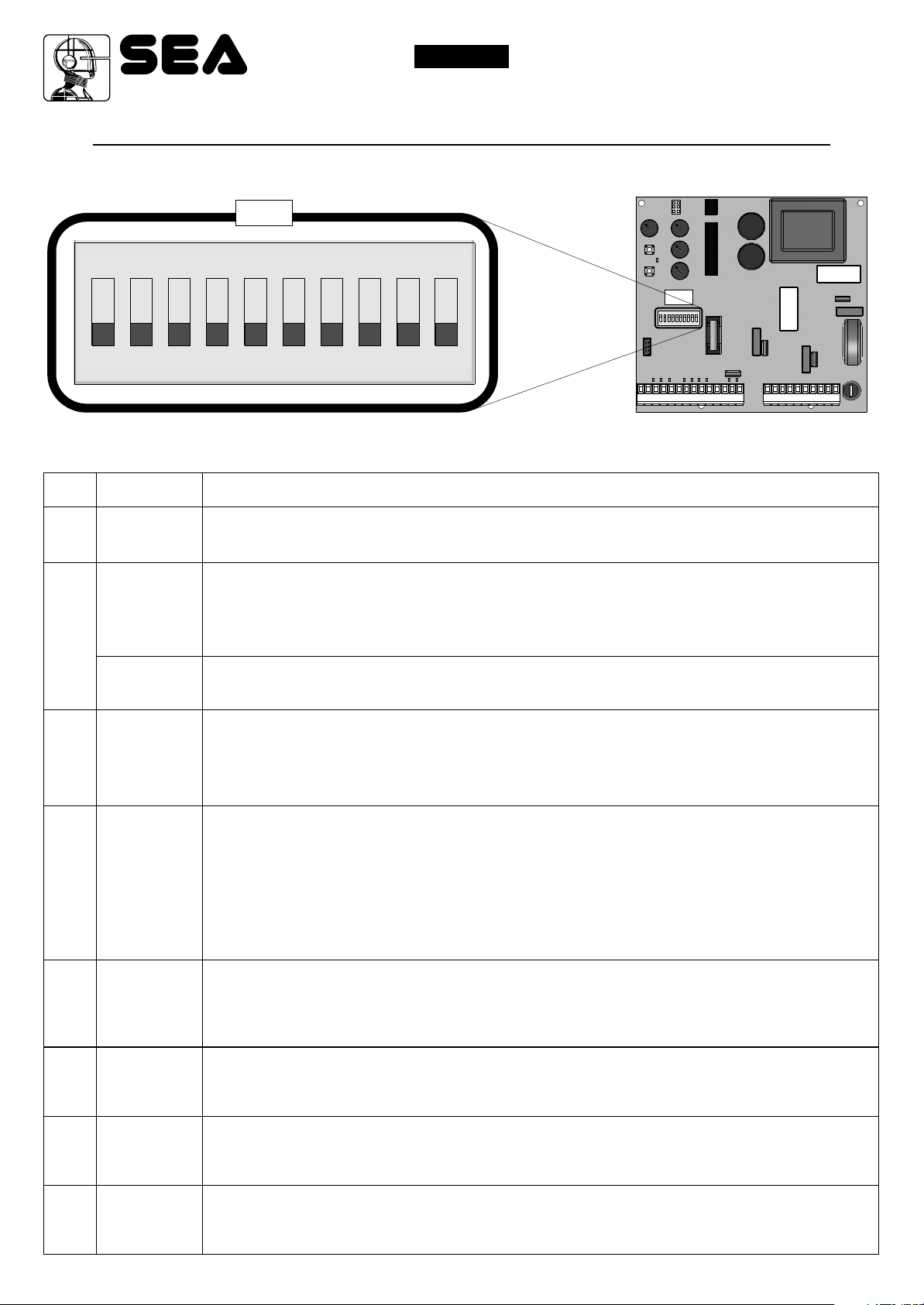
ADDITIONAL FUNCTIONS (DIP-SWITCH)
DIP
ON
DIP
1 2 3 4 5 6 7 8 9 10
DIP
3
4
5
6
POSITION
ON
ON
OFF
ON
ON
SETTING OF THE OTHER FUNCTIONS THROUGH DIP-SWITCH
PRE - FLASHING
When this function is activated the flashing lamp begins flashing about 3 seconds before the motor
starts to work, both in closing and opening.
SELFTEST PHOTOCELL
When this function is activated a test is executed on the photocells before the gate starts to move. In
order to enable this function the photocells transmitters must be connected to terminals
and 6 (Negative)
The selftest can be exclusively used with the imput photocell 1.
On the 24V Aux it is possible to connect the TX and the Rx of the photocell.
SLOWDOWN AND LIMIT SWITCH
When this function is activated motor speed reduces slowly before the gate reaches the limit switch
stop or before the operating time ends.This function is designed in order to get the leaf gently closer
to the mechanical stops, avoiding any noisy clash. The closing speed is fixed, while the slowdown
time can be adjusted using the trimmer Rv2.
LEAF LOCKING
When this function is activated, at the end of slowdown phase, and when the leaf has reached the
mechanical stop, the motor is supplied at maximum power for 1 second approximately. This
increases the oil pressure in the motor and makes the hydraulic lock more effective.
WARNING: this function must not be activated on a sliding gate since it could cause the over
- running of the limit switches, with following block of the automation.
(Through the PALM it is possible to exclude the PUSHOVER in opening).
of connector CN1.
10 (24VAux)
REVERSING STROKE
7
8
9
10
ON
ON
ON
ON
67410672 REV 00 - 06/2012
This function (to be used exclusively on swing gates) is useful to facilitate the electric lock release.
At the start impulse the leaves in closing phase are powered for 1 second approximately, before the
opening cycle starts..
SINGLE LEAF
On ON activates the single leaf function.
RECLOSING WITH PHOTOCELL
On ON activates the reclosing with photocell .
EDGE/TIMER
On ON changes the EDGE input into TIMER.
7
Sistemi Elettronici
di Apertura Porte e Cancelli
International registered trademark n. 804888
TRIMMER ADJUSTMENTS
®
English
Italiano
SWING 2 AMP
Rv1
Rv2
Rv3
Rv4
MOTOR TORQUE ADJUSTMENT
This trimmer allows to adjust the thrust force of the motor reducer. This kind of adjustment is required for operators
without mechanical / hydraulic device for power limitation. The adjustment must be executed so that there is no
crushing danger for people or objects and in any case in accordance with the law in force on the matter.
PAUSE TIME ADJUSTMENT
This trimmer allows the linear adjustment of pause time from 0 to 120 s (If you rotate it completely clockwise, you
can adjust the working logics setting it in half-automatics).
COURTESY LIGHT DELAY ADUSTMENT
Timer with double function: adjusts the lighting time of the courtesy light from 0 to 2 min. If completely turned anti-clockwise it
changes the output into a flashing lamp output.
Rv3
Rv2
Rv1
-
NOTE:
ROTATING THE
TRIMMER
CLOCKWISE
THE TIMES / VALUES
INCREASE
+
Rv4
SLOWDOWN DELAY ADJUSTMENT
ALARMS INDICATION TABLE
The flashes sequence,spaced with a pause, is showed on the flashing lamp (for about 20 seconds) .and on the control lamp
Number of flashes
1
2
3
4
Alarm type
Trial Test
Photocell in closing
Photocell in opening
Obstacle collision
Number of flashes
5
6
7
8
Alarm type
Safety edge
Stop
Phototest
Number max. Cycles
PALM FUNCTIONS
Control unit SWING 2 AMP with PALM administration
• Visualisation and modification of the following parameters:
• Working times
• Leaf delay
• Partial opening time
• 2 n. maintenance cycles adjustment
• Antisqueezing sensibility
• PhotoStop
• PhotoClose
• PushOpen ( excludes the pushover during opening phase)
8
67410672 REV 00 - 06/2012

®
Sistemi Elettronici
di Apertura Porte e Cancelli
International registered trademark n. 804888
English
Italiano
SWING 2 AMP
START, PEDESTRIAN START, STOP, ANTENNA
PHOTOCELLS 1 AND 2, ELECTRO-LOCK,
CN1
1 2 3 4 5 6 7 8 9 10 11 12 13 14
- - -
13
11
Photocells 1 Connection
When the photocells beam is crossed, the automation
reverses its movement if in closing phase.
For the photocell autotest connect the (+) of photocell 1
transmitter to terminal 10 instead of 12 and set Dip 4 on ON.
Note: If the photocell is not used put a jumper between
contact 7 and 6 of CN1.
Note: With DIP 9 it is possible to configure this photocell
12
+
as PHOTOCLOSE, or if employed during opening or
pause the automation will complete the opening.
+ = 24V - = 0V C = Contact Com = Common
N.C.
RX1
7
TX1
-
+
6
-
FLASHING LAMP, EDGE
SAFETY EDGE
When employed in opening or in closing
provoques the partial gate reversing.
9
6
24V FLASHING LAMP 15W Max(Control light)
It is recommended to use the 24V Flash Led flashing
lamp.
The warning lamp advises that the automatic gate is in
movement performing 1 flash /second in opening and 2
flashes / second in closing. Instead it remains turned on
fix during pause. To connect it, connect the wires of the
warning lamp as shown in the figure.
-
2 shield
Photocells 2 Connection
When the photocells beam is crossed, the automation reverses its
movement if in closing phase. In opening it causes the stop of the
gate until it is occupied, when released the gate returns into open
postion. Note: When not used make a jumper between contact 8
and 6 of CN1.
Note: With the PALM device it is possible to set as
6
PHOTOSTOP, that means that it does not allow to the gate to
-
open, while it does not intervene during the remaining opening.
+ = 24V - = 0V C = Contact Com = Common
Start
This entry manages the opening/closing of the
automation.
Pedestrian Start
It executes complete opening/closing of one only leaf.
Note: The partial opening is executed on motor 1.
Electro-lock
Note: it’s possible to connect
only one
electric lock.
12V
15VA max
11
14
12
TX2
+
RX2
8
N.C.
+
-
3
2
4
2
Antenna
Connect
the
antenna as
1
in the
picture.
2 5
Stop
The pressure of this button stops
the automation at any time. A
START impulse is required in
order to re-establish the
movement.
If not used put a jumper between
contact 2 and 5 of CN1.
67410672
REV 00 - 06/2012
9

®
Sistemi Elettronici
di Apertura Porte e Cancelli
International registered trademark n. 804888
English
Italiano
SWING 2 AMP
MOTORS, CAPACITORS, POWER SUPPLY
CN2
1 2 3 4 5 6 7 8 9 10
CN2
Courtesy light
Timeable from 0 to 2 min.
through Rv3.
If Rv3 is completely in anticlockwise position it is
possible to connect a 230V
Max 50W flashing lamp on the
courtesy light output
performing 1 flash in opening,
2 flashes in closing and stays
on during pause.
Capacitor 2
Capacitor 1
N P
NEUTRAL
7
8
1
2
4
5
PHASE 1
NEUTRAL
PHASE 2
PHASE 2
PHASE 1
546
3
2
1
Motor 2
Motors 2 outputs
M = OPENING/CLOSING
Com = COMMON
Motor 1
Motor 1 outputs
M = OPENING/CLOSING
Com = COMMON
Power supply
Power supply connection:
P = PHASE
N = NEUTRAL
10
67410672
M2
Example
M1
Example
9
10
REV 00 - 06/2012

®
Sistemi Elettronici
di Apertura Porte e Cancelli
International registered trademark n. 804888
English
Italiano
SWING 2 AMP
AMPEROMETRIC AND SELFLEARNING
MANAGEMENT ACTIVATION
(ONLY FOR ELECTROMECHANICAL OPERATORS)
The present control unit comes with an obstacle detection system for electromechanical operators.
To activate the operation keep pressed at the same time the PTime and PCode buttons for more or less 3
seconds. At this point Led P signalizes through the the set sensitivity through the number of flashings.
Sensitivity can be adjusted from 1 to 15, where value 1 stands for sensitivity OFF.
With PTime (-) button lower the sensitivity until it reaches the optimum value for your application (you
should take it to the value 5).
At this point with the gate on halfway and keeping pressed Ptime, the time programming will start. The
stops will be detected automatically and with PTime it is only necessary to point out the leaf delay points
in opening for M1 and in closing for M2.
The learning cycle will be: M2 closes - M1 closes - M1 opens (on the point desired for the leaf delay in
opening press PTime) - M2 opens - M2 closes (on the point desired for the leaf delay in closing press
Ptime) - M1 closes.
NOTE1: By default, the amperometric sensor is off, so, if you do not adjust the amperometric sensitivity,
the times learning must be made as reported on pages 12-13-14.
NOTE2: The amperometric detection is not guaranteed during slowdown, for gates with eccessive
weight and length and installed in less than optimal conditions. Furthermore, it is not guaranteed to work
on hydraulic motors and generally on motors not produced by SEA s.r.l.
67410672 REV 00 - 06/2012
11

®
Sistemi Elettronici
di Apertura Porte e Cancelli
International registered trademark n. 804888
English
Italiano
SWING 2 AMP
WORKING TIMES SELFLEARNING
ON SWING GATE
PHASE 1
Make all the electrical connections and take care to bridge all the unused N.C. contacts.
1
If you are installing a motor reducer equipped with mechanical / hydraulic anticrushing device, set the motor torque
(trimmer Rv1) at maximum value and make the motor torque adjustment using the appropriate by-pass valves or clutch
adjustment screws located on the operators.
If you are installing a motor reducer not equipped with mechanical / hydraulic power limitaiton device,set the motor
torque at maximum value ONLY during the selflearning phase. Immediately afterwards set a motor torque value which
can assure the anticrushing safety, in accordance with the law in forcei.
WARNING !
THIS PROCEDURE IS POTENTIALLY DANGEROUS AND MUST BE EXECUTED EXCLUSIVELY BY
SPECIALIZED STAFF UNDER SAFETY CONDITIONS.
PHASE 2
Disconnect the power supply (Fig. 1), release the gate (Fig. 2) and place the leaves at half-open position (Fig. 3). Re-
2
lock the motor (Fig. 4) and connect again the power supply (Fig. 5).
1 2 3 4 5
Release
F
F
O
Example
M1 M2
Example
Lock
PTime
Keep pressed PTime button, LEDP will
switch on.
Keep pressed PTime until the motor M2
starts to close*.
Release Ptime.
N
O
LEDP
PTime
12
67410672 REV 00 - 06/2012
PTime PTime
M2M1

®
Sistemi Elettronici
di Apertura Porte e Cancelli
International registered trademark n. 804888
English
Italiano
SWING 2 AMP
WORKING TIMES SELFLEARNING
ON SWING GATE
If the motos starts to open the gate, disconnect the power supply again, and reverse the motor phases.
*
Execute the same kind of connection on motor M1.
Repeat the programming procedurero (phase 2).
PHASE 3
Motor M2 closes (from step 2), when the leaf reaches the closing mechanical stop press the button PTime
3
(Fig. 6). Motor M1 will also start a closing cycle. When the leaf reaches the closing mechanical stop press
again the button PTime (Fig. 7).
M2M1
PTime PTime
Fig. 6
The gate stops and motor M1 starts an opening cycle. Press agin PTime in the point where you desire to set
the leaf delay in opening.
When the leaf reaches the mechanical stop in opening press once again PTime (Fig. 8).
At this point motor M2 also will start an opening cycle.
When the leaf will reach the mechanical stop in opening push once again PTime (Fig. 9).
M2M1
Fig. 7
M2M1
PTime PTime
Fig. 8
67410672 REV 00 - 06/2012
M2M1
Fig. 9
13

®
Sistemi Elettronici
di Apertura Porte e Cancelli
International registered trademark n. 804888
English
Italiano
SWING 2 AMP
WORKING TIMES SELFLEARNING
ON SWING GATE
Motor M2 will start automatically a closing cycle.Press again PTime in the point where you desire to set the
leaf delay in closing.
When the leaf reaches the mechanical stop in closing press once again PTime (Fig. 10).
At this point motor M1 will also start a closing cycle.
When the leaf reaches the mechanical stop in closing press once again PTime (Fig. 11).
M2M1
PTime PTime
Fig. 10
Programming is finished.
Check the correct times memorizing giving a start impulse or pressing the button PTime. If necessary repeat
the same learning procedure from step 2.
PHASE 4
4
In case of use use with motor reducer without mechanical / hydraulic device for motor torque limitation,
adjust trimmer Rv1 on values which can assure the anti-crushing safety in accordance with the law in force.
If after adjusting the motor torque the working time is not enough (the leaf doesn’t open / close completely),
repeat STEP 2 setting the motor torque value as for the usual use of the automation.
Adjust the slowdown time (if enabled), using trimmer Rv2.
M1
M2
Fig. 11
SINGLE LEAF MODE
1) Connect the motor cables to the terminals 4,5,6 of the CN2 terminal.
2) Set on ON DIP8 (single leaf mode).
3) Start the times programming by holding pressed Ptime button.
4) Make sure that the leaf starts closing (if not, remove the power supply).
5) On stop position in closing wait for 3 seconds and press Ptime, the leaf will automatically open.
6) On stop postion in opening wait for 3 seconds and press PTime, the leaf will automatically close.
7) On stop postion in closing wait for 3 seconds and press Ptime.
Selflearning completed.
14
67410672 REV 00 - 06/2012

®
Sistemi Elettronici
di Apertura Porte e Cancelli
International registered trademark n. 804888
English
Italiano
SWING 2 AMP
RADIO TRANSMITTERS MEMORIZING
!!
WARNING: Make the radio transmitters programming before you connect the antenna and insert the receiver into the
special CMR connector (if available) with turned off control unit. (The control unit automatically recognizes if the receiver is a RF,
RF Roll, RF Roll Plus or RF UNI module).
With RF Roll or RF Roll Plus module it will be possible to use only Coccinella Roll or Coccinella Roll Plus radio transmitters. or
Smart Dual Roll or Smart Dual Roll Plus.
With the RF UNI module it will be possible to use both the transmitters of the Roll Plus series and those with fixed code. The first
memorized transmitter determines the type of the remaining radio transmitters.
Make sure that on CMR connector is installed the receiver with the same frequency of the radio transmitter that you want to use.
Notes:
- Enter radio transmitters learning only when the working cycle stops and the gate is closed.
- If the radio transmitters are Rolling Code it’s possible to memorize up to 800 codes (buttons).
- If the radio transmitters are with fixed code it will be possible to memorize up to max. 30 codes (buttons).
RADIO TRANSMITTER MEMORIZING TO START
Press the button Pcode. LEDP will switch on.
PCode
LEDP
PCode
LEDP
Give an impulse with the radio transmitter, using the button which will be linked to the START impulse.
The led will execute two flashes Tx code and afterwards it will keep switching on waiting for new transmitters.
If no further code is memorized within 10 s the led will switch off automatically, getting out of the memorizing procedure.
WARNING: if you enter a code which is already memorized, it will be deleted.
RADIO TRANSMITTER MEMORIZING TO PEDESTRIAN START
1) Press the button PCode. LEDP will switch on.
2) Press the button PTime. LEDP will start to flash quickly.
1) 2)
LEDP
PCode
LEDP
PTime
LEDP
Give an impulse with the radio transmitter, using the button which will be linked to the pedestrian start impulse.
The Led will execute 2 long flashes in order to confirm the correct memorizing of Tx and afterwards it will keep switching on waiting for new
transmitters.
If no further code is memorized within 10 s the led will switch off automatically, getting out of the memorizing procedure.
WARNING: If a code is entered which already has been memorized, the transmitter will be deleted.
ALL RADIO TRANSMITTERS DELETING
Press and kepp pressing the button PCode.
LEDP will start a sequence of flashes.
Wait that the led stops to flash and release the button
PCode.
CANCELLATION OF SINGLE TRANSMITTER
Delete a single transmitter retransmitting the stored tranmsitter.
67410672
PCode
REV 00 - 06/2012
LEDP LEDP
PCode
15

®
English
Italiano
Sistemi Elettronici
di Apertura Porte e Cancelli
International registered trademark n. 804888
SAFETY LOOP CONNECTION
CN1
1 2 3 4 5 6 7 8 9 10 11 12 13 14
SWING 2 AMP
THIS SCHEME IS AN
EXPAMPLE FOR HOW TO
CONNECT EVENTUAL
MAGNETIC LOOPS.
Loop exit 1
Connecting scheme of loop 1
3 = Contact start (n.o.)
2 = Common
Loop exit 2
Connecting scheme of
loop 2
3 = Contact start (n.o.)
2 = Common
+
-
C1 = CONTACT OPEN
C2 = CONTACT CLOSED
12 = 24 V
11 = 0 V
Loop exit 1
Loop1
Loop exit 2
Loop2
Safety loop
Connecting scheme of loop 3
7 = Contact photocell (n.c.)
2 = Common
16
67410672
Safety loop
Loop3
Note: In reality all contacts can be set
as N.O. or N.C.
REV 00 - 06/2012

®
English
Italiano
Sistemi Elettronici
di Apertura Porte e Cancelli
International registered trademark n. 804888
TROUBLE SHOOTING
Advises
Make sure all Safety LED are turned ON
All not-used N.C. Contacts must be bridged
Problem Found
The motor doesn’t
respond to any START
impulse
a.) Bridge missing on one of the
N.C. contacts
b.) Burnt fuse
Possible Cause
SWING 2 AMP
Solutions
a.) Check the connections or the jumpers
on N.C. Contacts.
b.) Replace burnt fuse on the board
Gate doesn’t move
while the motor is
running
Gate doesn’t reach
the complete
open/close position
Gate opens but
doesn’t close
Gate doesn’t close
automatically
a.) The motor is in the released position
b.) Trimmer Rv1 is at minimum
c.) There is an obstacle or an obstacle is
detected but it is not really present
a.) Programming error
b.) Gate is stopped by an obstacle
c.) The fiting geometry is inadequate
d.) The obstacle detection sensitivity is too low
a.) The photocell or edge contacts
2/7, 2/8 and 2/9 are open.
a.) Pause time is too long
b.) The setted operating logic doesn’t include it
a.) Re/lock the motor
b.) Rotate Trimmer Rv1 at maximum
(rotate clockwise)
c.) Remove obstacle.
If obstacle detection is ON decrease the
sensitivity through PTime and PCode.
a.) Repeat the programming
b.) Remove the obstacle
c.) Check fitting geometry following
the operator installation manual.
d.) Increase the obstacle detection sensitivity
through PTime and PCode.
a.) Check LED or bridges
a.) Adjust the pause time using Trimmer Rv3
b.) Check dip1 and Trimmer Rv2 in
order to verify the setted logic
Page for both installer and user
WARNINGS
The electric installation and the functioning logic choice must agree with the laws in force. In any case you must foresee a 16A and threshold
0.030A differential switch. Keep the power cables (motors, power supply) separate from the command cables (push buttons, photocells and
so on). In order to avoid any interference it’s preferable to foresee and use two separate sheaths
REPLACEMENTS
Any request for spare parts must be sent to:
SEA s.r.l. - Zona Ind.le, 64020 S.ATTO - Teramo - Italia
SAFETY AND ENVIRONMENTAL COMPATIBILITY
Disposal of the packaging materials of products and/or circuits should take place in an approved disposal facility.
REGULAR PRODUCT DISPOSAL (electric and electronic waste)
(It’s applicable in EU countries and in those ones provided with a differential waste collection)
The brand that you find on the product or on documentation signals that the product must not be disposed off together with other domestic
waste at the end of life cycle. In order to avoid any possible environmental or health damage caused by irregular waste disposal, we
recommand to separate this product from other forms of waste and to recycle it in a responsible way in order to provide the sustainable reuse of material resources. Domestic users are invited to contact the retailer where the product has been purchased or the local office in
charge of all the information related to differential watse collection and recycling of this kind of product.
STORING
WAREHOUSING TEMPERATURES
T
min
- 40°C + 85°C
Materials handling must be made with appropriate vehicles..
WARRANTY LIMITS
For the guarantee see the sales conditions on the official SEA price list.
SEA reserves the right to make any required modification or change to the products and/or to this manual without any advanced notice
obligation.
67410672
T
Max
Dampness
min
Dampness
Max
5% Not condensing 90% Not condensing
REV 00 - 06/2012
17

®
SWING 2 AMP
Sistemi Elettronici
di Apertura Porte e Cancelli
International registered trademark n. 804888
CONDIZIONI DI VENDITA
EFFICACIA DELLE PRESENTI CONDIZIONI GENERALI DI VENDITA: Le presenti condizioni generali di vendita si applicano a tutti gli ordini
indirizzati a SEA s.r.l. Tutte le vendite fatte da SEA ai clienti sono regolate secondo le presenti condizioni di vendita che costituiscono parte
integrante del contratto di vendita ed annullano ogni clausola contraria o pattuizioni particolari presenti nell’ ordine o in altro documento
proveniente dall’ acquirente (cliente)
AVVERTENZE GENERALI Gli impianti di automazioni porte e cancelli vanno realizzati esclusivamente con componenti SEA, salvo accordi
specifici. L’inosservanza delle norme di sicurezza vigenti (Norm. EUROPEE EN 12453 - EN 12445 e altro) e di buona tecnica esclude la SEA
da ogni responsabilità. La SEA non risponde del mancato rispetto della corretta e sicura installazione secondo le norme.
1) PROPOSTA D’ORDINE La proposta d’ordine si intenderà accettata solo dopo la sua approvazione da parte della SEA. Conseguenza della
sua sottoscrizione, l’acquirente sarà vincolato alla stipula di un contratto d’acquisto, secondo quanto contenuto nella stessa proposta d’ordine
e nelle presenti condizioni di vendita. Viceversa, la mancata comunicazione all’acquirente dell’aprovazione della proposta d’ordine, non
comporta la sua automatica accettazione da parte della SEA
2) VALIDITÀ OFFERTA Le offerte proposte dalla SEA o dalla sua struttura commerciale periferica, avranno una validità di 30 giorni solari,
salvo diversa comunicazione in merito.
3) PREZZI I prezzi della proposta d’ordine sono quelli del listino in vigore alla data della redazione della stessa. Gli sconti applicati dalla
struttura commerciale periferica della SEA si intenderanno validi solo dopo la loro accettazione da parte della SEA. I prezzi si intendono per
merce resa franco ns. stabilimento in Teramo, esclusi IVA ed imballaggi speciali. La SEA si riserva il diritto di modificare in qualsiasi momento il
listino, dando opportuno preavviso alla rete di vendita. Le condizioni speciali riservate agli acquisti con formula agevolata Qx, Qx1, Qx2, Qx3
sono riservate ai distributori ufficiali dietro accettazione scritta da parte della direzione SEA.
4) PAGAMENTI Le forme di pagamento ammesse sono quelle comunicate o accettate di volta in volta dalla SEA. Il tasso di interesse sul ritardo
da pagamento è del 1,5% mensile e comunque non oltre il tasso massimo legalmente consentito.
5) CONSEGNA La consegna avverrà indicativamente ma non tassativamente entro 30 giorni lavorativi dalla data di ricezione dell’ordine, salvo
diverse comunicazioni in merito. Il trasporto degli articoli venduti sarà effettuato a spese ed a rischio dell’acquirente. La SEA si libera
dall’obbligo della consegna rimettendo la merce al vettore, sia esso scelto dalla SEA oppure dall’acquirente. Eventuali smarrimenti e/o
danneggiamenti della merce dovuti al trasporto, sono a carico dell’acquirente.
6) RECLAMI Eventuali reclami e/o contestazioni dovranno pervenire alla SEA entro 8 giorni solari dalla ricezione della merce, supportati da
idonei documenti provanti la loro veridicità.
7) FORNITURA L’ordine in oggetto viene assunto da SEA senza alcun impegno e subordinatamente alle possibilità di approvvigionamento
delle materie prime occorrenti alla produzione; eventuali mancate esecuzioni totali o parziali non possono dar luogo a reclami e riserve per
danni. La fornitura SEA è strettamente limitata alla sola merce di sua produzione, esclusi il montaggio, l’installazione ed il collaudo. La SEA
declina pertanto ogni responsabilità per danni che dovessero derivare, anche a terzi, dall’inosservanza delle norme di sicurezza e della buona
regola d’arte nelle fasi dell’installazione e dell’impiego dei prodotti venduti.
8) GARANZIA La garanzia minima è di 12 mesi e può essere estesa, come di seguito, in caso di riconsegna del certificato di garanzia.
SILVER: Le parti meccaniche degli operatori rientranti in tale categoria sono garantite per 24 mesi dalla data di fabbricazione riportata
sull’operatore.
GOLD: Le parti meccaniche degli operatori rientranti in tale categoria sono garantite per 36 mesi dalla data di fabbricazione riportata
sull’operatore.
PLATINUM: Le parti meccaniche degli operatori rientranti in tale categoria sono garantite per 36 mesi dalla data di fabbricazione riportata
sull’operatore. La garanzia di base (36 mesi) sarà estesa per ulteriori 24 mesi (fino ad un totale di 60 mesi) qualora venga acquistato il
certificato di garanzie che dovrà essere compilato e rispedito alla SEA s.r.l. entro 60 giorni dall’acquisto. L’elettronica e le centrali di comando
sono garantite per 24 mesi dalla data di fabbricazione. Nell’eventualità di difettosità del prodotto, la SEA si impegna alla sua sostituzione
gratuita oppure alla sua riparazione, previa restituzione al proprio centro di riparazione. La definizione di stato di garanzia è ad insindacabile
giudizio della SEA. I pezzi sostitutivi restano di proprietà della SEA. In modo vincolante, il materiale dell’acquirente ritenuto in garanzia deve
essere spedito al centro di riparazione della SEA in porto franco e sarà rispedito dalla SEA in porto assegnato. La garanzia non si estende alla
manodopera eventualmente accorsa. I difetti riconosciuti non produrranno alcuna responsabilità e/o richiesta di danni, di qualsiasi natura essi
siano, da parte dell’acquirente nei riguardi della SEA. La garanzia non è in ogni caso riconosciuta qualora sia stata apportata alla merce
qualsivoglia modifica, oppure vi sia stato un uso improprio, oppure si sia in presenza di una qualsivoglia sua manomissione o di un montaggio
non corretto, oppure se sia stata rimossa l’etichetta apposta dal produttore comprensiva del marchio SEA registrato n° 804888. La garanzia
non è inoltre valida nel caso la merce SEA sia stata in parte o in toto accoppiata a componenti meccanici e/o elettronici non originali, ed in
particolare in assenza di una specifica autorizzazione in merito, ed inoltre nel caso in cui l’acquirente non sia in regola con i pagamenti. La
garanzia non comprende danni derivati dal trasporto, materiale di consumo, avarie dovute al mancato rispetto delle specifiche prestazionali
dei prodotti indicate nel listino. Non è riconosciuto alcun indennizzo durante il tempo di riparazione e/o sostituzione della merce in garanzia. La
SEA declina ogni responsabilità per danni a cose o persone derivanti dall’inosservanza delle norme di sicurezza e della non conforme
installazione o dall’impiego errato dei prodotti venduti. La riparazione dei prodotti in garanzia e fuori garanzia è subordinata al rispetto delle
procedure comunicate da SEA.
9) RISERVATO DOMINIO Sulla merce venduta è valida la clausola del riservato dominio, della quale la SEA deciderà autonomamente se
avvalersi o meno, in virtù della quale l’acquirente acquisisce la proprietà della merce, solo dopo che il suo pagamento sia stato completamente
effettuato.
10) FORO COMPETENTE Per qualsiasi controversia avente per oggetto l’applicazione di questo contratto, viene eletto competente il Foro di
Teramo. La lingua valida nell’ interpretazione di cataloghi, manuali di installazione, condizioni di vendita o altro è quella italiana. La SEA si
riserva la facoltà di apportare modifiche tecniche atte a migliorare i propri prodotti, presenti o meno in questo Listino, in qualsiasi momento
senza preavviso. La SEA declina ogni responsabilità derivante da possibili inesattezze contenute nel presente listino, derivanti da errori di
stampa e/o trascrizione. Il presente Listino annulla e sostituisce quelli precedenti. L’acquirente ai sensi della legge 196/2003 (codice privacy)
acconsente all’inserimento dei propri dati personali derivanti dal presente contratto negli archivi informatici e cartacei della SEA s.r.l. al loro
trattamento per motivi commerciali ed amministrativi.
Diritti di proprietà industriale: il cliente, con l’acquisto, accetta le presenti condizioni di vendita e riconosce in capo a SEA la titolarità
esclusiva del marchio internazionale SEA registrato n. 804888 apposto sulle etichette dei prodotti e/o sui manuali e/o su ogni altra
documentazione, e si impegna ad utilizzare il medesimo nella propria attività di rivendita e/o installazione secondo modalità che non ne
riducano in alcun modo i diritti, a non rimuovere, sostituire o alterare marchi o altri segni distintivi di qualsiasi genere apposti ai prodotti.
E’ vietata ogni forma di riproduzione o utilizzo del marchio SEA e di ogni altro segno distintivo presente sui prodotti, salvo autorizzazione scritta
di SEA srl.
Agli effetti dell’articolo 1341 del C.C. si approvano specificatamente per iscritto le clausole di cui ai numeri:
4) PAGAMENTI - 8) GARANZIA - 10) FORO COMPETENTE
18
67410672 REV 00 - 06/2012

®
SWING 2 AMP
Sistemi Elettronici
di Apertura Porte e Cancelli
International registered trademark n. 804888
TERMS OF SALES
EFFICACY OF THE FOLLOWING TERMS OF SALE: the following general terms of sale shall be applied to all orders sent to SEA srl.
All sales made by SEA to all costumers are made under the prescription of this terms of sales which are integral part of sale contract
and cancel and substitute all apposed clauses or specific negotiations present in order document received from the buyer.
GENERAL NOTICE The systems must be assembled exclusively with SEA components, unless specific agreements apply. Noncompliance with the applicable safety standards (European Standards EM12453 – EM 12445) and with good installation practice
releases SEA from any responsibilities. SEA shall not be held responsible for any failure to execute a correct and safe installation under
the above mentioned standards.
1) PROPOSED ORDER The proposed order shall be accepted only prior SEA approval of it. By signing the proposed order, the Buyer
shall be bound to enter a purchase agreement, according to the specifications stated in the proposed order.
On the other hand, failure to notify the Buyer of said approval must not be construed as automatic acceptance on the part of SEA.
2) PERIOD OF THE OFFER The offer proposed by SEA or by its branch sales department shall be valid for 30 solar days, unless
otherwise notified.
3) PRICING The prices in the proposed order are quoted from the Price List which is valid on the date the order was issued. The
discounts granted by the branch sales department of SEA shall apply only prior to acceptance on the part of SEA. The prices are for
merchandise delivered ex-works from the SEA establishment in Teramo, not including VAT and special packaging. SEA reserves the
right to change at any time this price list, providing timely notice to the sales network. The special sales conditions with extra discount
on quantity basis (Qx, Qx1, Qx2, Qx3 formula) is reserved to official distributors under SEA management written agreement.
4) PAYMENTS The accepted forms of payment are each time notified or approved by SEA. The interest rate on delay in payment shall
be 1.5% every month but anyway shall not be higher than the max. interest rate legally permitted.
5) DELIVERY Delivery shall take place, approximately and not peremptorily, within 30 working days from the date of receipt of the
order, unless otherwise notified. Transport of the goods sold shall be at Buyer’s cost and risk. SEA shall not bear the costs of delivery
giving the goods to the carrier, as chosen either by SEA or by the Buyer. Any loss and/or damage of the goods during transport, are at
Buyer’s cost.
6) COMPLAINTS Any complaints and/or claims shall be sent to SEA within 8 solar days from receipt of the goods, proved by adequate
supporting documents as to their truthfulness.
7) SUPPLY The concerning order will be accepted by SEA without any engagement and subordinately to the possibility to get it’s
supplies of raw material which is necessary for the production; Eventual completely or partially unsuccessful executions cannot be
reason for complains or reservations for damage. SEA supply is strictly limited to the goods of its manufacturing, not including
assembly, installation and testing. SEA, therefore, disclaims any responsibility for damage deriving, also to third parties, from noncompliance of safety standards and good practice during installation and use of the purchased products.
8) WARRANTY The standard warranty period is 12 months. This warranty time can be extended by means of expedition of the
warranty coupon as follows:
SILVER: The mechanical components of the operators belonging to this line are guaranteed for 24 months from the date of
manufacturing written on the operator.
GOLD: The mechanical components of the operators belonging to this line are guaranteed for 36 months from the date of
manufacturing written on the operator.
PLATINUM: The mechanical components of the operators belonging to this line are guaranteed for 36 months from the date of
manufacturing written on the operator. The base warranty (36 months) will be extended for further 24 months (up to a total of 60
months) when it is acquired the certificate of warranty which will be filled in and sent to SEA s.r.l. The electronic devices and the
systems of command are guaranteed for 24 months from the date of manufacturing. In case of defective product, SEA undertakes to
replace free of charge or to repair the goods provided that they are returned to SEA repair centre. The definition of warranty status is by
unquestionable assessment of SEA. The replaced parts shall remain propriety of SEA. Binding upon the parties, the material held in
warranty by the Buyer, must be sent back to SEA repair centre with fees prepaid, and shall be dispatched by SEA with carriage forward.
The warranty shall not cover any required labour activities.
The recognized defects, whatever their nature, shall not produce any responsibility and/or damage claim on the part of the Buyer
against SEA. The guarantee is in no case recognized if changes are made to the goods, or in the case of improper use, or in the case of
tampering or improper assembly. Furthermore, the warranty shall not apply if SEA products are partly or completely coupled with nonoriginal mechanical and/or electronic components, and in particular, without a specific relevant authorization, and if the Buyer is not
making regular payments. The warranty shall not cover damage caused by transport, expendable material, faults due to nonconformity with performance specifications of the products shown in the price list. No indemnification is granted during repairing and/or
replacing of the goods in warranty. SEA disclaims any responsibility for damage to objects and persons deriving from non-compliance
with safety standards, installation instructions or use of sold goods.
9) RESERVED DOMAIN A clause of reserved domain applies to the sold goods; SEA shall decide autonomously whether to make use
of it or not, whereby the Buyer purchases propriety of the goods only after full payment of the latter.
10) COMPETENT COURT OF LAW In case of disputes arising from the application of the agreement, the competent court of law is the
tribunal of Teramo. SEA reserves the faculty to make technical changes to improve its own products, which are not in this price list at
any moment and without notice. SEA declines any responsibility due to possible mistakes contained inside the present price list
caused by printing and/or copying. The present price list cancels and substitutes the previous ones. The Buyer, according to the law
No. 196/2003 (privacy code) consents to put his personal data, deriving from the present contract, in SEA archives and electronic files,
and he also gives his consent to their treatment for commercial and administrative purposes. Industrial ownership rights: once the
Buyer has recognized that SEA has the exclusive legal ownership of the registered SEA brand, he will commit himself to use it in a way
which does not reduce the value of these rights, he won’t also remove, replace or modify brands or any other particularity from the
products. Any kind of replication or use of SEA brand is forbidden as well as of any particularity on the products, unless preventive and
expressed authorization by SEA.
In accomplishment with art. 1341 of the Italian Civil Law it will be approved expressively clauses under numbers:
4) PAYMENTS - 8) GUARANTEE - 10) COMPETENT COURT OF LOW
67410672 REV 00 - 06/2012
19

®
Sistemi Elettronici
di Apertura Porte e Cancelli
International registered trademark n. 804888
Italiano
AVVERTENZE GENERALI PER INSTALLATORE E UTENTE
1. Leggere attentamente le Istruzioni di Montaggio e le Avvertenze Generali prima di iniziare l’installazione del prodotto. Conservare la documentazione per
consultazioni future
2. Non disperdere nell’ ambiente i materiali di imballaggio del prodotto e/o circuiti
3. Questo prodotto è stato progettato e costruito esclusivamente per l’utilizzo indicato in questa documentazione. Qualsiasi altro utilizzo non espressamente indicato
potrebbe pregiudicare l’integrità del prodotto e/o rappresentare fonte di pericolo. L’uso improprio è anche causa di cessazione della garanzia. La SEA srl declina
qualsiasi responsabilità derivata dall’uso improprio o diverso da quello per cui l’automatismo è destinato.
4. I prodotti SEA sono conformi alle Direttive: Macchine (2006/42/CE e successive modifiche), Bassa Tensione (2006/95/CE e successive modifiche), Compatibilità
Elettromagnetica (2004/108/CE e successive modifiche). L’installazione deve essere effettuata nell’osservanza delle norme EN 12453 e EN 12445.
5. Non installare l’apparecchio in atmosfera esplosiva.
6. SEA srl non è responsabile dell’inosservanza della Buona Tecnica nella costruzione delle chiusure da motorizzare, nonché delle deformazioni che dovessero
verificarsi durante l’ uso.
7. Prima di effettuare qualsiasi intervento sull’impianto, togliere l’alimentazione elettrica e scollegare le batterie. Verificare che l’impianto di terra sia realizzato a
regola d’arte e collegarvi le parti metalliche della chiusura.
8. Per ogni impianto SEA srl consiglia l’utilizzo di almeno una segnalazione luminosa nonché di un cartello di segnalazione fissato adeguatamente sulla struttura
dell’infisso.
9. SEA srl declina ogni responsabilità ai fini della sicurezza e del buon funzionamento della automazione, in caso vengano utilizzati componenti di altri produttori.
10. Per la manutenzione utilizzare esclusivamente parti originali SEA.
11. Non eseguire alcuna modifica sui componenti dell’automazione.
12. L’installatore deve fornire tutte le informazioni relative al funzionamento manuale del sistema in caso di emergenza e consegnare all’Utente utilizzatore
dell’impianto il libretto d’avvertenze allegato al prodotto.
13. Non permettere ai bambini o persone di sostare nelle vicinanze del prodotto durante il funzionamento. L’applicazione non può essere utilizzata da bambini, da
persone con ridotte capacità fisiche, mentali, sensoriali o da persone prive di esperienza o del necessario addestramento. Tenere inoltre fuori dalla portata dei
bambini radiocomandi o qualsiasi altro datore di impulso, per evitare che l’automazione possa essere azionata involontariamente.
14. Il transito tra le ante deve avvenire solo a cancello completamente aperto.
15. Tutti gli interventi di manutenzione, riparazione o verifiche periodiche devono essere eseguiti da personale professionalmente qualificato. L’utente deve
astenersi da qualsiasi tentativo di riparazione o d’intervento e deve rivolgersi esclusivamente a personale qualificato SEA. L’utente può eseguire solo la manovra
manuale.
16. La lunghezza massima dei cavi di alimentazione fra centrale e motori non deve essere superiore a 10 m. Utilizzare cavi con sezione 2.5 mm . Utilizzare cablaggi
con cavi in doppio isolamento (cavi con guaina) nelle immediate vicinanze dei morsetti specie per il cavo di alimentazione (230V). Inoltre è necessario mantenere
adeguatamente lontani (almeno 2.5 mm in aria) i conduttori in bassa tensione (230V) dai conduttori in bassissima tensione di sicurezza (SELV) oppure utilizzare
un’adeguata guaina che fornisca un isolamento supplementare avente uno spessore di almeno 1 mm.
2
English
GENERAL NOTICE FOR THE INSTALLER AND THE USER
1. Read carefully these Instructions before beginning to install the product. Store these instructions for future reference
2. Don’t waste product packaging materials and /or circuits.
3. This product was designed and built strictly for the use indicated in this documentation. Any other use, not expressly indicated here, could compromise the good
condition/operation of the product and/or be a source of danger. SEA srl declines all liability caused by improper use or different use in respect to the intended one.
4. The mechanical parts must be comply with Directives: Machine Regulation 2006/42/CE and following adjustments), Low Tension (2006/95/CE), electromgnetic
Consistency (2004/108/CE) Installation must be done respecting Directives: EN12453 and En12445.
5. Do not install the equipment in an explosive atmosphere.
6. SEA srl is not responsible for failure to observe Good Techniques in the construction of the locking elements to motorize, or for any deformation that may occur
during use.
7. Before attempting any job on the system, cut out electrical power and disconnect the batteries. Be sure that the earthing system is perfectly constructed, and
connect it metal parts of the lock.
8. Use of the indicator-light is recommended for every system, as well as a warning sign well-fixed to the frame structure.
9. SEA srl declines all liability as concerns the automated system’s security and efficiency, if components used, are not produced by SEA srl.
10. For maintenance, strictly use original parts by SEA.
11. Do not modify in any way the components of the automated system.
12. The installer shall supply all information concerning system’s manual functioning in case of emergency, and shall hand over to the user the warnings handbook
supplied with the product.
13. Do not allow children or adults to stay near the product while it is operating. The application cannot be used by children, by people with reduced physical, mental
or sensorial capacity, or by people without experience or necessary training. Keep remote controls or other pulse generators away from children, to prevent
involuntary activation of the system.
14. Transit through the leaves is allowed only when the gate is fully open.
15. The User must not attempt to repair or to take direct action on the system and must solely contact qualified SEA personnel or SEA service centers. User can apply
only the manual function of emergency.
16. The power cables maximum length between the central engine and motors should not be greater than 10 m. Use cables with 2,5 mm section. Use double
2
insulation cable (cable sheath) to the immediate vicinity of the terminals, in particular for the 230V cable. Keep an adequate distance (at least 2.5 mm in air), between
the conductors in low voltage (230V) and the conductors in low voltage safety (SELV) or use an appropriate sheath that provides extra insulation having a thickness
of 1 mm.
Français
CONSIGNES POUR L’INSTALLATEUR ET L’UTILISATEUR
1. Lire attentivement les instructions avant d’installer le produit.Conserver les instructions en cas de besoin.
2. Ne pas dispenser dans l’ environnement le materiel d’ emballage du produit et/ou des circuits
4. Ce produit a été conçu et construit exclusivement pour l’usage indiqué dans cette fiche. Toute autre utilisation non expressément indiquée pourraient
compromettre l’intégrité du produit et/ou représenter une source de danger. SEA srl décline toute responsabilités qui dériverait d’usage impropre ou différent de celui
auquel l’automatisme est destiné.Une mauvaise utilisation cause la cessation de la garantie.
5. Les composants doivent répondre aux prescriptions des Normes: Machines (2006/42/CE et successifs changements); Basse Tension (2006/95/CE et successifs
changements); EMC (2004/108/CE et successifs changements). L’installation doit être effectuée conformément aux Normes EN 12453 et EN 12445.
6. Ne pas installer l’appareil dans une atmosphère explosive.
7. SEA srl n’est pas responsable du non-respect de la Bonne Technique de construction des fermetures à motoriser, ni des déformations qui pourraient intervenir lors
de l’utilisation.
8. Couper l’alimentation électrique et déconnecter la batterie avant toute intervention sur l’installation.Vérifier que la mise à terre est réalisée selon les règles de l’art
et y connecter les pièces métalliques de la fermeture.
9. On recommande que toute installation soit doté au moins d’une signalisation lumineuse, d’un panneau de signalisation fixé, de manière appropriée, sur la
structure de la fermeture.
10. SEA srl décline toute responsabilité quant à la sécurité et au bon fonctionnement de l’automatisme si les composants utilisés dans l’installation n’appartiennent
pas à la production SEA.
20
67410672 REV 00 - 06/2012

®
Sistemi Elettronici
di Apertura Porte e Cancelli
International registered trademark n. 804888
11. Utiliser exclusivement, pour l’entretien, des pièces SEA originales.
12. Ne jamais modifier les composants d’automatisme.
13. L’installateur doit fournir toutes les informations relatives au fonctionnement manuel du système en cas d’urgence et remettre à l’Usager qui utilise l’installation
les “Instructions pour l’Usager” fournies avec le produit.
14. Interdire aux enfants ou aux tiers de stationner près du produit durant le fonctionnement. Ne pas permettre aux enfants, aux personnes ayant des capacités
physiques, mentales et sensorielles limitées ou dépourvues de l’expérience ou de la formation nécessaires d’utiliser l’application en question. Eloigner de la portée
des enfants les radiocommandes ou tout autre générateur d’impulsions, pour éviter tout actionnement involontaire de l’automatisme.
15. Le transit entre les vantaux ne doit avoir lieu que lorsque le portail est complètement ouvert.
16. L’utilisateur doit s’abstenir de toute tentative de réparation ou d’intervention et doigt s’adresser uniquement et exclusivement au personnel qualifié SEA ou aux
centres d’assistance SEA. L’utilisateur doigt garder la documentation de la réparation. L’utilisateur peut exécuter seulement la manoeuvre manuel.
17. La longueur maximum des câbles d’alimentation entre la carte et les moteurs ne devrait pas être supérieure à 10 m. Utilisez des câbles avec une section de 2,5
2
mm . Utilisez des câblage avec cable à double isolation (avec gaine) jusqu’à proximité immédiate des terminaux, en particulier pour le câble d’alimentation (230V). Il
est également nécessaire de maintenir une distance suffisante (au moins 2,5 mm dans l’air), entre les conducteurs en basse tension (230V) et les conducteurs de
très basse tension de sécurité (SELV) ou utiliser une gaine ayant une épaisseur d’au moin 1 mm, qui fournisse une isolation supplémentaire.
Español
ADVERTENCIAS GENERALES PARA INSTALADORES Y USUARIOS
1 Leer las instrucciones de instalación antes de comenzar la instalación. Mantenga las instrucciones para consultas futura
2. No disperdiciar en el ambiente los materiales de embalaje del producto o del circuito
3. Este producto fue diseñado y construido exclusivamente para el uso especificado en esta documentación. Cualquier otro uso no expresamente indicado puede
afectar la integridad del producto y ser una fuente de peligro. El uso inadecuado es también causa de anulación de la garantía. SEA srl se exime de toda
responsabilidad causadas por uso inapropiado o diferente de aquel para el que el sistema automatizado fue producido.
4. Los productos cumplen con la Directiva: Maquinas (2006/42/CE y siguientes modificaciones), Baja Tension (2006/95/CE, y siguientes modificaciones),
Compatibilidad Electromagnética (2004/108/CE modificada). La instalación debe ser llevada a cabo de conformidad a las normas EN 12453 y EN 12445.
5. No instalar el dispositivo en una atmósfera explosiva.
6. SEA srl no es responsable del incumplimiento de la mano de obra en la construcción de la cacela a automatizar y tampoco de las deformaciones que puedan
producirse durante el uso.
7. Antes de realizar cualquier operación apagar la fuente de alimentación y desconectar las baterías. Comprobar que el sistema de puesta a tierra sea diseñado de
una manera profesional y conectar las partes metálicas del cierre.
8. Para cada instalación se recomienda utilizar como mínimo una luz parpadeante y una señal de alarma conectada a la estructura del marco.
9. SEA srl no acepta responsabilidad por la seguridad y el buen funcionamiento de la automatización en caso de utilización de componentes no producidos por SEA.
10. Para el mantenimiento utilizar únicamente piezas originales SEA srl.
11. No modificar los componentes del sistema automatizado.
12. El instalador debe proporcionar toda la información relativa al funcionamiento manual del sistema en caso de emergencia y darle al usuario el folleto de adjunto
al producto.
13. No permita que niños o adultos permanecen cerca del producto durante la la operación. La aplicación no puede ser utilizada por niños, personas con movilidad
reducida de tipo fìsico, mental, sensorial o igual por personas sin experiencia o formación necesaria. Tener los radiomandos fuera del alcance de niños asì como
cualquier otro generador de impulsos radio para evitar que el automación pueda ser accionada accidentalmente.
14. El tránsito a través de las hojas sólo se permite cuando la puerta está completamente abierta.
15. Todo el mantenimiento, reparación o controles deberán ser realizados por personal cualificado. Evitar cualquier intente a reparar o ajustar. En caso de necesitad
comunicarse con un personal SEA calificado. Sólo se puede realizar la operación manual.
16. La longitud máxima de los cables de alimentación entre motor y central no debe ser superior a 10 metros. Utilizar cables con 2,5 mm . Utilizar cables con doble
2
aislamiento (cables con váina) hasta muy cerca de los bornes, especialmente por el cable de alimentación (230V). Además es necesario mantener adecuadamente
distanciados (por lo menos 2,5 mm en aire) los conductores de baja tensión (230V) y los conductores de baja tensión de seguridad (SELV) o utilizar una váina
adecuada que proporcione aislamiento adicional con un espesor mínimo de 1 mm.
Deutsch
ALLGEMEINE HINWEISE FUER DEN INSTALLATEUR UND DEN NUTZER
1.Lesen Sie die Installierungsanweisungen sorgfältig durch bevor Sie mit der Installierung beginnen.Diese Anweisungen an einem leicht zugänglichen Ort
aufbewahren.
2.Verpackungsmaterial des Produkts und/oder der Schaltkreise umweltgerecht entsorgen.
3. Dieses Produkt wurde speziell und ausschließlich für den, in den Unterlagen beschriebenen Zweck, geplant und hergestellt. Jede andere Verwendung, die nicht
ausdrücklich angegeben wurde kann die Integrität des Produkts schädigen und/oder eine Gefahrenquelle darstellen. Die nicht fachgerechte Nutzung des Produkts
bewirkt die Erlöschung der Garantie. SEA S.r.l. lehnt jegliche Haftung, für unsachgemäße oder andere Nutzung, als die wofür das Produkt bestimmt ist, ab.
4. SEA Produkte entsprechen den folgenden Richtlinien: Maschinenrichtlinie (2006/42/EG und nachträglich geänderten Fassungen), Niederspannungs-Richtlinie
(2006/95/EG und nachträglich geänderten Fassungen), EMV (2004/108/EG und nachträglich geänderten Fassungen). Installation gemäß Standard EN12453 und
EN12445 durchführen.
5. Installieren Sie das Gerät nicht in explosionsgefährdeten Umgebungen, das Vorhandensein von brennbaren Gasen oder Dämpfen stellt ein ernstes
Sicherheitsrisiko dar.
6. SEA S.r.l. ist nicht für die Nichtbeachtung der Guten Technik bei der Herstellung von zu motorisierenden Toren und für deren eventuellen Verformungen, die
während des Gebrauchs auftreten könnten, haftbar.
7. Vor allen Eingriffen, das Gerät ausschalten und die Batterien trennen. Sicherstellen, dass die Erdung fachgerecht hergestellt wurde und die Metallteile des Tores
daran anschließen.
8. Für jede Anlage wird empfohlen, mindestens ein Blinklicht zu montieren und ein Warnschild auf der Torstruktur anzubringen.
9. SEA S.r.l. übernimmt keine Haftung für Sicherheit und reibungslosen Betrieb des Antriebs, bei Verwendung von Komponenten, die nicht von der SEA Produktion
stammen.
10. Für die Wartung nur SEA Originalteile verwenden.
11. Keinerlei Änderungen auf Komponenten der Automation vornehmen.
12. Der Installateur muss den Nutzer des Antriebs über den manuellen Betrieb des Systems im Notfall unterrichten und ihm, das, dem Produkt beiliegende,
Handbuch übergeben.
13. Der Aufenthalt von Kindern oder Erwachsenen in der Nähe des Tores während seines Betriebes ist nicht gestattet. Die Anlage darf nicht von Kindern,
Personen mit eingeschränkten körperlichen, geistigen oder sensorischen Fähigkeiten oder von Menschen ohne notewendige Erfahrung oder Anweisungen benutzt
werden. Fernbedienungen oder andere Impulsgeber außerhalb der Reichweite von Kindern halten, um die versehentliche Aktivierung der Anlage zu verhindern.
14. Die Durchfahrt zwischen den Flügeln ist nur bei vollständig geöffnetem Tor zulässig.
15. Sämtliche Wartungs-und Reparaturarbeiten oder periodische Kontrollen, müssen von qualifiziertem Fachpersonal durchgeführt werden. Der Endverbraucher
muss davon absehen eigenständig Reparaturen oder Eingriffe jeder Art an der Anlage durzuführen und muss sich aussschliesslich an qualifiziertes SEA
Fachersonal wenden. Der Endverbraucher darf nur die manuelle Notfunktion durchführen.
16. Die maximale Länge der Stromkabel zwischen Steuerung und Motoren ist 10 Meter. Verwenden Sie Kabel mit 2,5 mm Querschnitt und Doppelisolierung
2
(Kabelmantel) in der unmittelbaren Nähe von Klemmen, insbesondere für das Speisungskabel (230V). Die Speisungskabel (230V) und die SicherheitsNiederspannugnskabel (SELV) müssen in einem Abstand von mindestens 2,5 mm gehalten werden, oder eine geeignete Hülse von 1mm Dicke , für eine
zusätzliche Isolierung verwenden..
67410672 REV 00 - 06/2012
21

®
Sistemi Elettronici
di Apertura Porte e Cancelli
International registered trademark n. 804888
Dichiarazione di conformità
Declaration of Conformity
La SEA s.r.l. dichiara sotto la propria responsabilità e, se applicabile, del suo rappresentante
autorizzato che il prodotto:
SEA srl declares under its proper responsability and, if applicable, under the responsability of its
authorised representative that the product:
Descrizione / Description Modello / Model Marca / Trademark
SWING 2 AMP (e tutti i suoi derivati) 23021093/94 SEA
SWING 2 AMP (and all its by-products) 23021093/94 SEA
è costruito per essere incorporato in una macchina o per essere assemblato con altri macchinari per
costruire una macchina ai sensi della Direttiva 2006/42/CE:
is built to be integrated into a machine or to be assembled with other machinery to create a machine
under the provisions of Directive 2006/42/CE:
è conforme ai requisiti essenziali di sicurezza relativi al prodotto entro il campo di applicabilità delle
Direttive Comunitarie 2006/95/CE e 2004/108/CE.
it is conforming to the essential safety requirements related to the product within the field of applicability
of the Community Directives 2006/95/CE and 2004/108/CE.
COSTRUTTORE o RAPPRESENTANTE AUTORIZZATO:
MANUFACTURER or AUTHORISED REPRESENTATIVE:
SEA S.r.l.
DIREZIONE E STABILIMENTO:
Zona industriale 64020 S.ATTO Teramo - (ITALY)
Tel. +39 0861 588341 r.a. Fax +39 0861 588344
Http://www.seateam.com
I test sul prodotto sono stati effettuati in configurazione standard e in riferimento alle norme specifiche
per la sua classe d'utilizzo.
The products have been tested in standard configuration and with reference to the special norms
concerning the classe of use.
22
(Luogo, data di emissione)
(Place, date of issue)
Teramo, 05/06/2012
67410672
REV 00 - 06/2012

Questo articolo è stato prodotto seguendo rigide procedure
di lavorazione ed è stato testato singolarmente al fine di
garantire i più alti livelli qualitativi e la vostra soddisfazione.
Vi ringraziamo per aver scelto SEA.
This item has been produced following strict production
procedures and has been singularly tested for the highest
quality levels and for your complete satisfaction.
Thanks for choosing SEA.
Cet article a été produit suivant des procédures d'usinage
strictes et il a singulièrement été testé afin de garantir
les plus hauts niveaux de qualité pour votre satisfaction.
Nous vous remercions d'avoir choisi SEA.
Este articulo ha sido producido siguiendo rigidos
procedimientos de elaboracion y ha sido probando
singolarmente a fin de garantizar los mas altos inveles de
calidad y vuestra satisfaccion.
Le agradecemos por haber escogito SEA.

®
Sistemi Elettronici
di Apertura Porte e Cancelli
International registered trademark n. 804888
SEA S.r.l.
Zona industriale 64020 S.ATTO Teramo - (ITALY)
Tel. +39 0861 588341 r.a. Fax +39 0861 588344
www.seateam.com
seacom@seateam.com
 Loading...