

SEA GATE 2 User Manual
International registered trademark n. 2.777.971
GATE 2
CONTROL UNIT
67410191

GATE 2
International registered trademark n. 2.777.971
TABLE OF CONTENTS
SAFETY INSTRUCTIONS ..........................................................................................................................3
PARTS SPECIFICATIONS..........................................................................................................................5
CONNECTIONS..........................................................................................................................................6
SLOW-DOWN MODE, DIP SWITCHES LOGIC PROGRAM......................................................................7
OPERATING TORQUE ADJUSTMENT......................................................................................................9
BRAKE (SLOW DOWN) LENGTH ADJUSTMENT.....................................................................................9
PAUSE LENGTH ADJUSTMENT................................................................................................................9
LEDS...........................................................................................................................................................9
RADIO RECEIVER, START BUTTON CONNECTIONS...........................................................................10
PHOTOCELLS, BUZZER CONNECTIONS ..............................................................................................11
ELECTRIC LOCK, MAGNETIC LOCK, SOLENOID LOCK CONNECTIONS...........................................12
SAFETY EDGE, FLASHING LAMP, COURTESY LIGHT, TIMER CONNECTIONS.................................13
POWER SUPPLY, MOTORS, CAPACITORS CONNECTIONS FOR HYDRAULIC OPERATORS ..........14
POWER SUPPLY, MOTORS, CAPACITORS CONNECTIONS FOR ALPHA OPERATORS ...................15
ANTENNA, SAFETY GATE, STOP BUTTON CONNECTIONS................................................................16
SELF-LEARNING OF OPERATING TIME FOR SWING GATES OPERATORS ......................................17
PROGRAMMING A TRANSMITTER ON START......................................................................................20
PROGRAMMING A TRANSMITTER ON PARTIAL START ......................................................................20
LOOP DETECTOR WIRING .....................................................................................................................21
TROUBLESHOOTING ..............................................................................................................................23
SALES CONDITIONS AND WARRANTY .................................................................................................24
2
REV 05 - 10/2010
GATE 2
International registered trademark n. 2.777.971
WARNING: Not following these instructions may
cause severe injury or death to person
IMPORTANT SAFETY INSTRUCTIONS
WARNING - To reduce risk of severe injury or death:
1) READ AND FOLLOW ALL INSTRUCTIONS
2) Never let children operate or play with door controls. Keep the remote control away
from children.
3) Always keep the moving system in sight and away from people and objects until it is
completely closedor stopped. NO ONE SHOULD CROSS THE PATH OF THE
MOVING SYSTEM.
4) Test the system gate operator monthly. The system MUST reverse on contact with a
rigid object or when an object activates the non-contact sensors. To obtain a reverse on
contact with an object on hydraulic linear and in-ground operators SEA recommend to
install the patented safety device “SAFETY GATE” for each leaf.
After adjusting the force or the limit of the travel, retest the gate operator. Failure to
adjust properly the gate operator properly can increases the risk of severe injury or
death.
5) Use the manual release only when gate is not moving
6) KEEP GATES PROPERLY BALANCED AND MAINTAINED. An improper balancing
or maintenance increases the risk of severe injury or death. Have a qualified service
personal to make repairs to cables, spring assemblies and other hardware.
7)The entrance with a gate operators system is for vehicles only. Pedestrian MUST use
separate entrance.
8) Every gate operator installation MUST have secondary protection devices against
entrapment, such as edge sensors and photo beams more in particularly in places
where the risk of entrapment is more likely to occure.
END USER ISTRUCTIONS
The installer is responsible for grounding the operator system,
for providing the main power breaker switch, and for making sure
that the entire gate systems meets all applicable electrical codes.
SAVE THESE INSTRUCTIONS
REV 05 - 10/2010
3
International registered trademark n. 2.777.971
Good grounding and proper surge suppression are an integral part of proper installation for
a gate operator system. One or all of the following may require surge suppressors: high
voltage power lines, low voltage power lines, telephone lines, data lines, low voltage control
lines and loops. How much surge suppression is required depends upon how susceptible
the area is to lightning and power surges. Regardless, good grounding is essential. To
realize maximum protection, proper grounding and proper surge suppression is absolutely
necessary.
If the circuit breaker box is located close to the gate operator system, for example, in a
guard house, then the ground from that circuit can be used to ground the gate operator
system. Eliminate all 90° bends in ground wires and keep a minimum of three feet between
the surge suppressor and the equipment being protected.
If the power source or circuit breaker box is not located close to the gate operator system an
Isolated Ground Zone (IGZ) needs to be created. An IGZ can also be created if the circuit
breaker box is located close by the gate operator system. An IGZ is an imaginary circle
drawn around the gate operator system. The gate operator system not only includes the
gate operators and control panel, but all of the accessories and devices associated with it at
that controlled entry point. This includes loop detectors, card readers, digital entries,
telephone entries, any device that has a ground or requires a ground and ali of the surge
suppressors. The ground bus is a common ground point calied a Single Point Ground
(SPG). It is used to bond all the equipment and device grounds in the IGZ together. The
SPG is very important because it helps eliminate different ground potentials that can be
present on the equipment. In such cases, equipment damage occurs even with surge
suppressors.
GATE 2
GROUNDING
Do not use or connect the ground wire coming from the circuit breaker box. By using an
Isolated Ground Zone, you are separating the gate operator system from the house or
building ground. This eliminates ground potentials. It is recommended that the ground bus
be located in a separate NEMA type enclosure. All grounds will be tied to this ground bus.
Some points to remember:
Keep all ground wires as straight as possible. Do not have any sharp 90° bends. Have a
minimum of 3 feet of wire between the surge suppressor and the equipment being
protected.
Equipment ground wire should be a minimum of 12 AWG. The main ground wire from the
bus bar to the ground rod shouid be an 8 or 6 AWG copper wire. Ground rod should be a
minimum of 10 feet in length, longer depending on local soil conditions.
For more information regarding good grounding practices check: National Electric Code
art. 250; IEEE Emerald Book, standard 100; International Association of Electric
Inspectors.
SAVE THESE INSTRUCTIONS
READ AND FOLLOW ALL INSTRUCTIONS
IMPORTANT SAFETY INSTRUCTIONS
4
REV 05 - 10/2010
International registered trademark n. 2.777.971
GATE 2
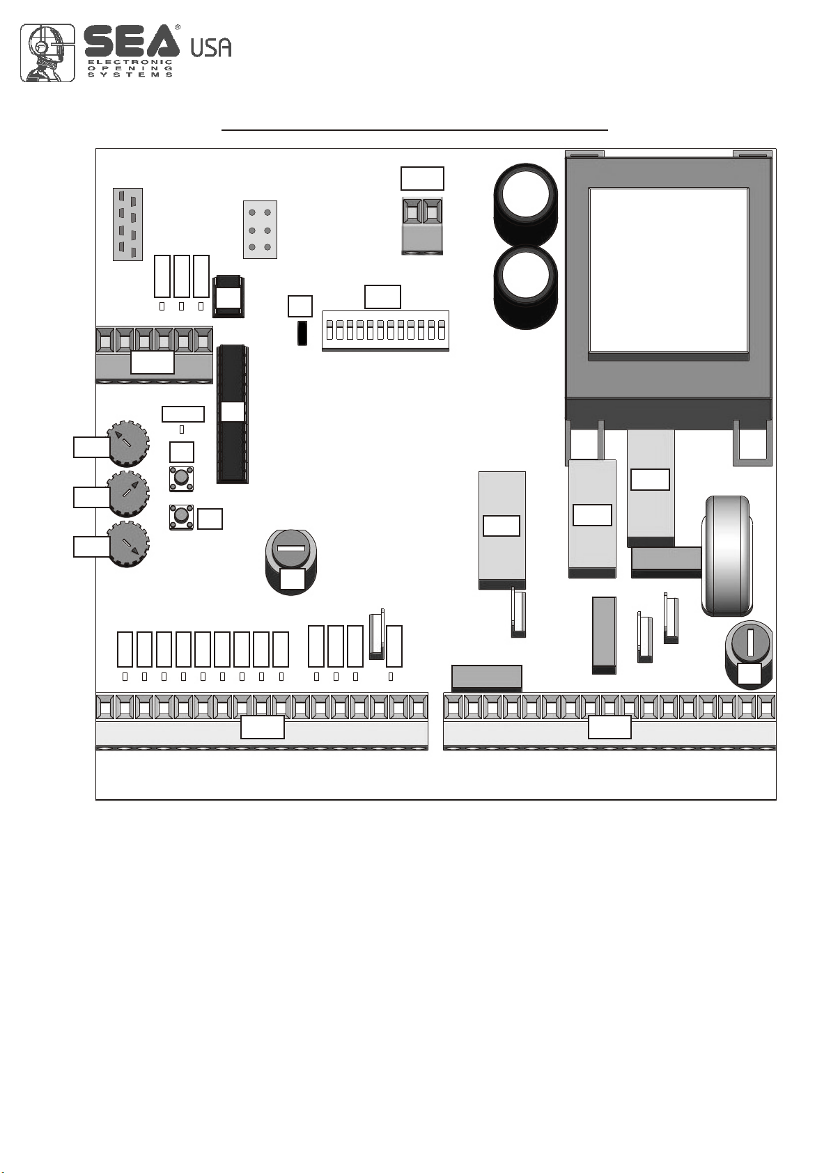
PARTS SPECIFICATION
Rv3
Rv2
Rv1
CMR
CN1
LED14
LED15
LEDPLEDP
P1
LED16
P2
U2
U1
CNP
F2
J1
DIP
CN4
RL1
RL3
RL2
LED5
LED6
LED7
LED8
LED1
LED2
LED3
LED4
GREEN ORANGE
LED9
LED10
LED11
LED1 = Auxiliary input
LED2 = Partial Start
LED3 = Start
LED4 = Limit switch in closing Motor 2
LED5 = Limit switch in opening Motor 2
LED6 = Limit switch in closing Motor 1
LED7 = Limit switch in opening Motor 1
LED8 = Photocell 2
LED9 = Photocell 1
LED10 = 24V Auxiliary output
LED11 = Tx Photocell output
LED12 = Troubleshooting LED
LED13 = Electric Lock
LED14 = Encoder (reversing sensor) 2
LED15 = Encoder (reversing sensor) 1
LED16 = Stop
LEDP = Programming
CN1 = 24V input / output connector
LED12
LED13
REV 05 - 10/2010
F1
CN3CN2
CN2 = 24V input / output connector (green)
CN3 = Motors and Power supply connector (orange)
CN4 = 24Vac Photosync connector
Rv1 = Motor torque adjustment
Rv2 = Brake length adjustment (slow down length)
Rv3 = Pause time adjustment
P1 = Operating time memory button
P2 = Programming transmitters button
DIP = Dip-switch Function Setting
F1 = Output and motor fuse (6.3AT)
F2 = Accessories fuse (2A)
J1 = Slow-down adjustment
RL1 = Motor Power Supply Relay
RL2 = Motor Operating Direction Relay
RL3 = Garden Light Relay
U1 = Micro-controller
U2 = EEPROM memory
CMR = Receiver module connector
CNP = PALM connector
5
CN2
(Green)
GATE 2
International registered trademark n. 2.777.971
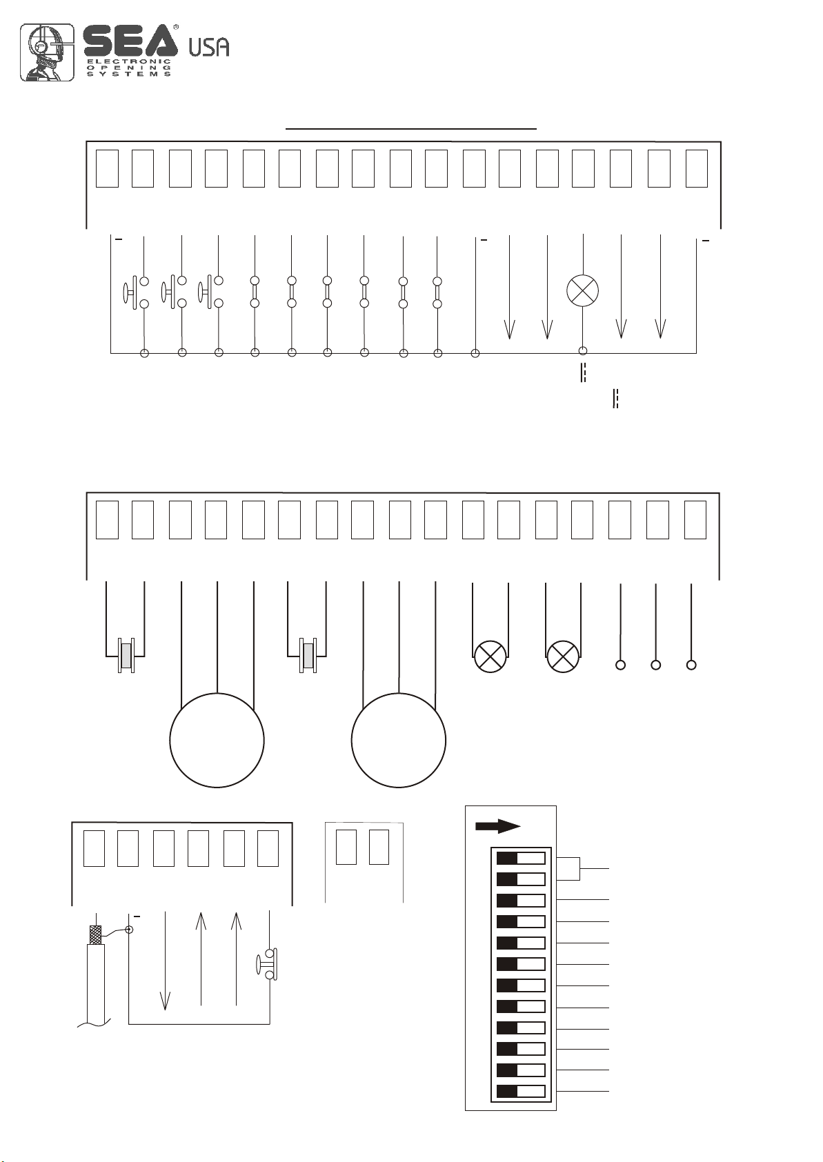
CONNECTIONS
1 2 3 4 5 6 7 8 9 10 1112 13 14 15
l
r
tA
T
AR
n
mo
i pu
T
S
o n
C m
ATTENTION NOTE: In the configuration of the swing gate double leaf the limit switches must not be bridged.
ar
i y
al
l
iar
t
xi
u
P
T
R
A
ST
ch
t
i
sw
t
Limi
2
2
M t
g
n
l o or
c osi
hLi
c
r
t
tch
i
i
t
s
w
sw
t
M
mit
g o o
Limi
in
n
ope
1
1
chLi
t
i
t
o or
o or
sw
t
M
M
g
g
mi
n
n
i
i
os
en
l
c
op t
)
l
l
e
otoc l 2
h
P
)
el 1
i g
n
i g
n n(
s
l
hotoc
c o
ope
(
P
no
o
m
C m
r
ili y
x
u
A
c
d a
V
24
l
e
itt
m2
ns
a
r
T
V
4
V
otoce
4
h
2
p
r
e
z
uz
B
16 17
x
m a
0 A m
V
0
4
24
VL
1
2
ck
o
CN3
(Orange)
1 2 3 4 5 6 7 8 9 10 1112 13 14 15 16 17
mCo
m on
ing
g
os
in
Cl
Open
tor
i
a M2
p c
~
M2
Ca
M1
r
to
i
pac
Ca
g
in
n
Ope
~
M1
mC
om on
ng
i
os
Cl
al
ndGr
r
ht
V
y lig
es
15
t
1
r
e
h
15V
as
l
1
F
t
eu
N
u
o
Cour
n
o
mm
o
C
seP
ha
6
CN1
1 2 3 4 5 6
wn
r
B o
e
Gr en
g
L
i
s
I
e n
R A
vr
e
E
R
A
o
esr
sn
p
o
p ly
s
u
e r
r s
. s
v n
we
po
Re
e
t
i
h
W
ig
r
v
eesn
R
r2
s
no
e
s
e
i
h t
W
g
n
i
e
vrs
e
R
1
o esr
sn
P
O
ST
CN4
11 22
24V~
Note: For
the power
supply of the
synchronized
photocells.
REV 05 - 10/2010
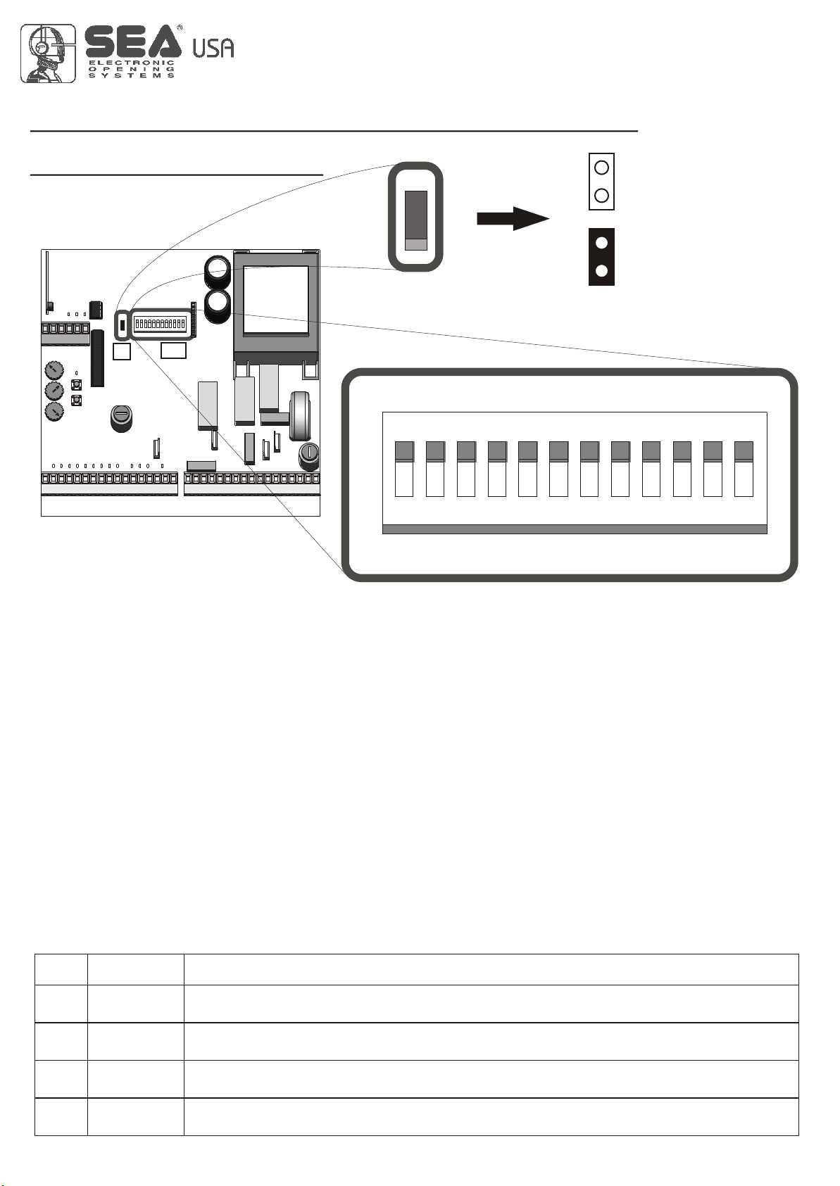
DIP
ONON
ON= Function Active
11 22 33 44 55 66 77 88 99 1010 1111 1212
Operating logics
Auxiliary input configuration
Leaf delay in opening and closing
Pre-flashing
Automatic closing
Photocell autotest
Reversing sensor (Safety Gate)
Soft start
Brake (slow-down)
Leaf locking
Reverse stroke
International registered trademark n. 2.777.971
SLOW-DOWN MODE, DIP SWITCHES,
GATE 2
LOGIC PROGRAM
J1
WORKING LOGICS
Four different working logics can be selected.
The programming takes place using DIP1 and DIP2.
DIP
J1
Slow-down mode
(only DIP 10 ON)
DIP
ON
1 2 3 4 5 6 7 8 9
Choose the slow down
1
modality which can be
more appropriate for
the installation.
1: Jumper unconnected
2
2: Jumper connected
10 11 12
- MANUAL LOGIC
A START command opens the gate. A second START while it is opening stops the motor.
A START command while it is closing stops the motor.
Important note: For the automatic re-closure, set DIP 6 on ON
- SAFETY LOGIC
A START command opens the gate. A second START while it is opening reverses the motor.
A START command while it is closing reverses the motor.
Important note: For the automatic re-closure, set DIP 6 on ON
- AUTOMATIC LOGIC 1
A START command opens the gate. A second START while it is opening is not accepted. A START while it is closing
reverses the direction.
P. N.: for automatic closing, set DIP SWITCH 6 to the ON position.
Important note: For automatic closing, set DIP SWITCH 6 to the ON position.
Important note: If Dip 6 of the automatic closing is not activated the start in pause will be accepted.
- AUTOMATIC LOGIC 2
A START command opens the gate. A second START while it is opening is not accepted. A START during the pause time closes the
gate immediately. A START while it is closing reverses the direction.
P. N.: for automatic closing, set DIP SWITCH 6 to the ON position.
P. N.: For automatic closing, set DIP SWITCH 6 to the ON position.
DIP
1 / 2
OPENED
CLOSED
OFF / OFF
DIP1 AND DIP2 PROGRAMMING FOR THE SELECTION OF THE WORKING LOGIC
If Dip1 and Dip2 are programmed in this way, the control unit will work with Manual Logic
1 / 2
1 / 2
1 / 2
ON / OFF
OFF / ON
ON / ON
If Dip1 and Dip2 are programmed in this way, the control unit will work with Safety Logic
If Dip1 and Dip2 are programmed in this way, the control unit will work with Automatic 1 Logic
If Dip1 and Dip2 are programmed in this way, the control unit will work with Automatic 2 Logic
REV 05 - 10/2010
7

International registered trademark n. 2.777.971
DIP SWITCHES, LOGIC PROGRAM
GATE 2
3
3
4
5
6
7
8
9
10
11
12
OPENED
CLOSED
OFF
ON
OPENED
CLOSED
ON
ON
ON
ON
ON
ON
ON
ON
ON
DIP
DIP
8
DIP 3 AND DIP 4 PROGRAMMING FOR AUXILIARY INPUT CONFIGURATION
SAFETY EDGE ( N.C. contact)
When the Safety Edge Contact opens, the gate reverses direction and stops after about 1 second. A
START command is required to restart movement
TIMER (N.O. contact)
If a TIMER is connected to this input the gate can be opened and kept open as long as the contact
remains closed. Using a 24-hour or 7-day timer allows gate opening times to be scheduled as
required. When the TIMER contact is open the automatic operation functions according to pre-set
logics.
PROGRAMMING OF OTHER DIPS FOR OTHER FUNCTIONS
LEAF DELAY IN OPENING AND CLOSING
Activating this function, the Leaf Delay in opening and closing will be eliminated. Both leaves will
work simultaneously. It is advised to activate this function on single leaf applications and/or in
applications where the Delay is not required.
PRE-FLASHING
When this function is activated the flashing lamp and warning light begin flashing about 3 seconds
before the motor starts, both when closing and opening.
AUTOMATIC CLOSING
Activating this function causes the gate to close automatically, after the time set by the trimmer Rv3.
This function can be activated independently of the operating logic set (DIP SWITCH 1 and 2).
PHOTOCELL AUTOTEST
When this function is activated a test is carried out on the photocells before any gate movement
takes place. To enable this function the photocell transmitter must be connected to terminals 13
(24V) and 17 (Negative) of connector CN2.
The flashing lamp and troubleshooting LED will both flash slowly if a malfunction occurs.
ENCODER MANAGEMENT (reversing sensor)
The signals sent from an encoder located on the motor or gate are managed when this function is activated.
This results in any obstacles found in the gate's path being detected and reverses the gate direction of
movement for one second, it stops and waits for commands. The flashing lamp and troubleshooting LED will
both flash slowly if a malfunction occurs. With a following start the automation will proceed in slow down
speed until it reaches the stop. Note: After two consecutive obstacles the BUZZER will be activated.
P.N.: If an encoder is not fitted, set the DIP SWITCH to OFF.
Note: The Encoder sensibility can be adjusted through the PALM or through the pushbuttons Ptime
and Pcode on board of the control unit.
“SOFT” START
When this function is activated, the motor will start at a lower torque to avoid stresses and strains on
the gate's mechanical components. The starting torque is a percentage of the normal operating
torque.
P.N.: It is not advised to operate this function when the gate is very heavy or does not run smoothly.
BRAKING (slow-down) AT LIMIT SWITCH
When this function is activated motor speed reduces slowly before the limit switch is reached or
before the end of the operating time. This function is designed to bring the leaf gently up to the stop
position and prevent the gates clashing. The closing speed is fixed, while the slow-down time can be
adjusted using the trimmer Rv2.
Remember to set this DIP in Off position in case of mechanical or hydraulic brake.
! !
It is necessary to activate this function to choose the slow-down modality through jumper J1.
LEAF LOCKING
When this function is activated, at the end of the slow-down phase, and when the leaf is up against
the mechanical stop, the motor is supplied at maximum power for about 1 second. This increases
the oil pressure in the motor and makes the hydraulic lock more effective.
P.N.: this function SHOULD NOT be activated when used on sliding gates since it could
cause over-running of the limit switches and the automation system to jam.
Note2: With the Palm through the function PushOpen it is possible to exclude the tightening
of the leaf during the opening phase.
REVERSING STROKE
This function (to use exclusively on swing gates) is used to facilitate the electric lock release. Before
beginning the opening cycle, as soon as the start order is given, the leaves are supplied for about 1
sec. in closing.
REV 05 - 10/2010
 Loading...