


Installation instructions for Standard front steer I.F.S.
Scotts Hotrods 3421 Galaxy Place Oxnard CA 93030 (805) 485-0382
Rev: A Installation Manual for Standard front steer IFS
Installation Manual for Standard front steer IFS
Please note a few things before beginning:
Check the parts list thoroughly to be sure all items are there. If any items appear to be missing immediately call our tech department. Remember, you must call within 30 days of receipt or you may be responsible for missing parts. Do not begin installation until all parts are received. This will make it much easier to complete the installation
These instructions serve merely as a guideline. Scotts Hotrods can only assume this installation will be done at a gualified installation shop or by a qualified installer. These instructions will guide you step by step through the basics: however Scotts Hotrods cannot accept any liability for differences in this instruction manual, and your particular vehicle. Scotts Hotrods recommends that all items to be welded be done so by a certified welder. We also recommend TIG welding all items.
Review our warranty online at www.scottshotrods.com
Tools recommended for installation:

Complete Standard socket set


Soap stone or other marking utensil

Complete Standard Allen Wrench set


uisher is also a good item to keep handy!!


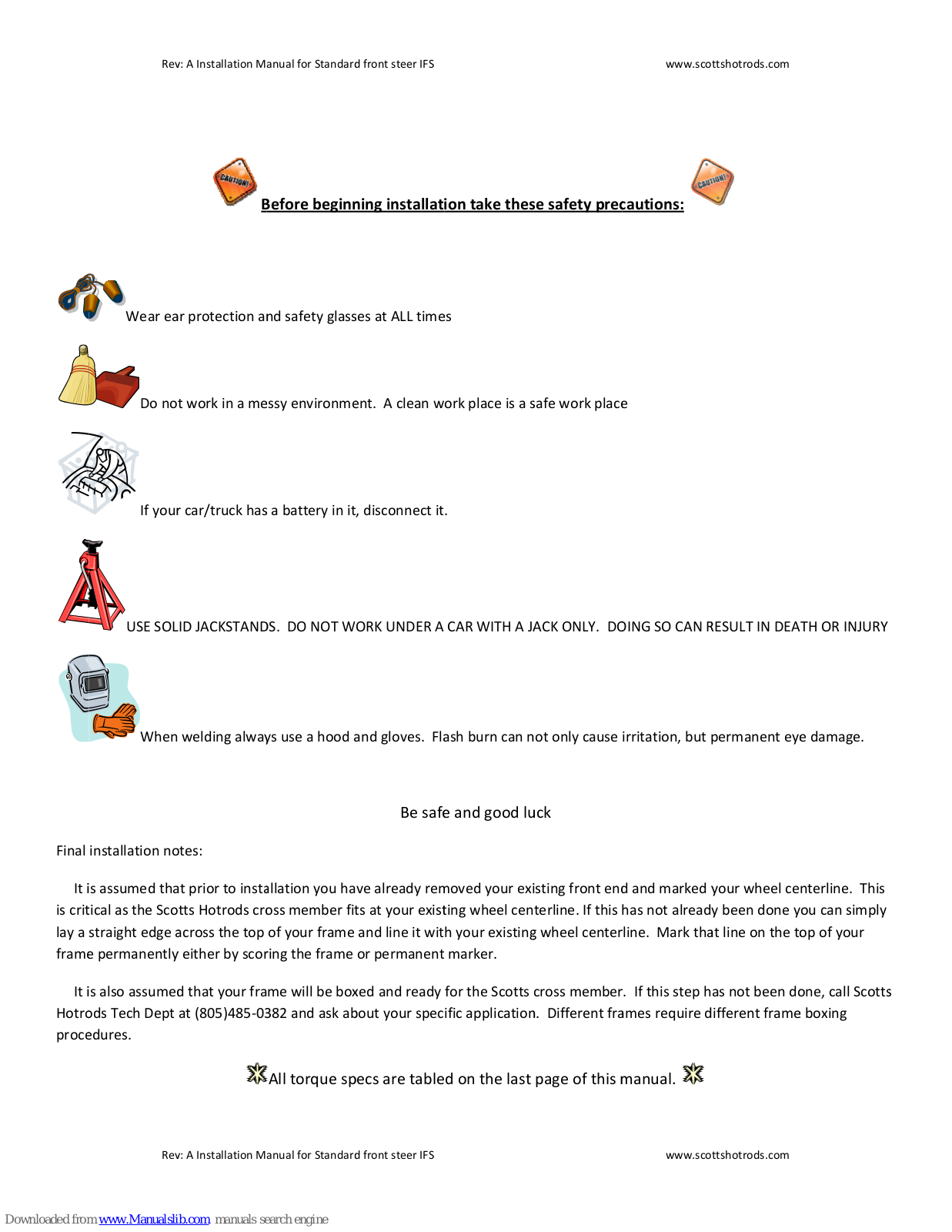
Wear ear protection and safety glasses at ALL times

If your car/truck has a battery in it, disconnect it.
USE SOLID JACKSTANDS. DO NOT WORK UNDER A CAR WITH A JACK ONLY. DOING SO CAN RESULT IN DEATH OR INJURY
/hen welding always use a hood and gloves. Flash burn can not only cause irritation, but permanent eye damage.
Be safe and good luck
Final installation notes:
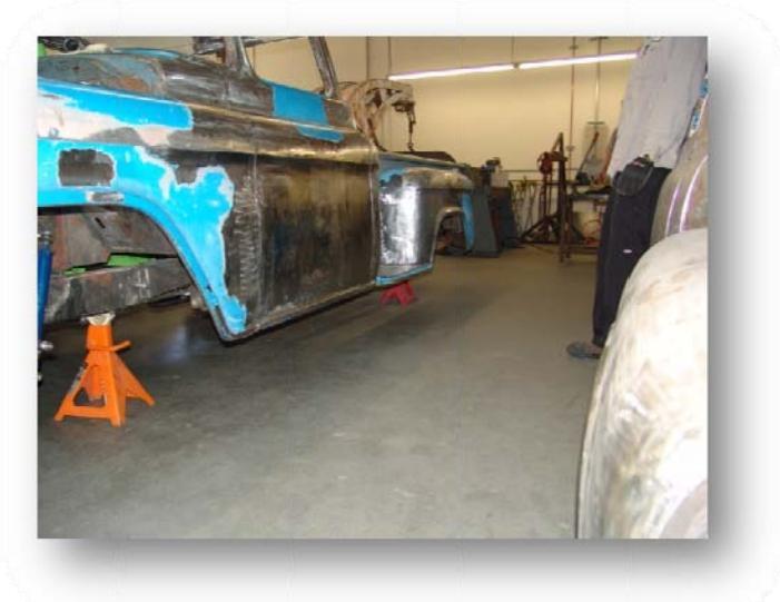
It is assumed that prior to installation you have already removed your existing front end and marked your wheel centerline. This is critical as the Scotts Hotrods cross member fits at your existing wheel centerline. If this has not already been done you can simply lay a straight edge across the top of your frame and line it with your existing wheel centerline. Mark that line on the top of your frame permanently either by scoring the frame or permanent marker.
It is also assumed that your frame will be boxed and ready for the Scotts cross member. If this step has not been done, call Scotts Hotrods Tech Dept at (805)485-0382 and ask about your specific application. Different frames require different frame boxing procedures.

Rev: A Installation Manual for Standard front steer IFS
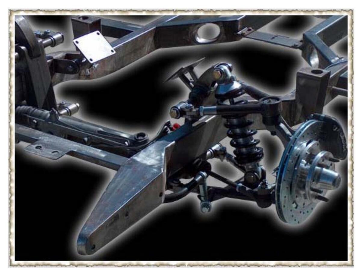
Crossmember installation
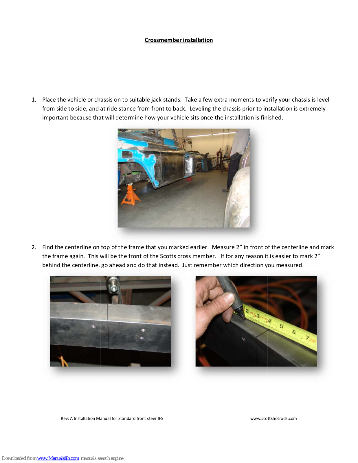
1. Place the vehicle or chassis on to suitable jack stands. Take a few extra moments to verify your chassis is level from side to side, and at ride stance from front to back. Leveling the chassis prior to installation is extremely important because that will determine how your vehicle sits once the installation is finished.
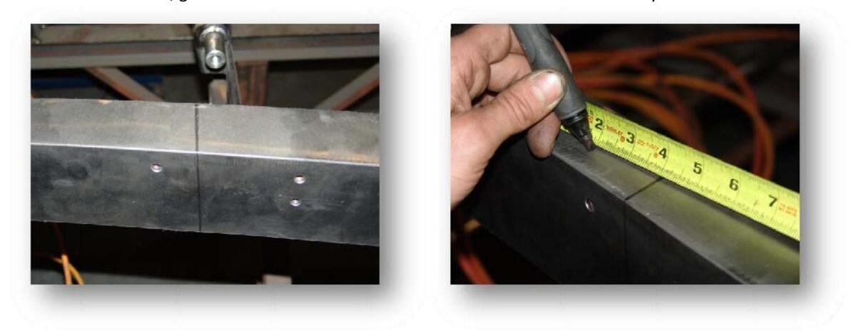
2. Find the centerline on top of the frame that you marked earlier. Measure 2" in front of the centerline and mark the frame again. This will be the front of the Scotts cross member. If for any reason it is easier to mark 2" behind the centerline, go ahead and do that instead. Just remember which direction you measured.
Rev: A Installation Manual for Standard front steer IFS
Crossmember installation cont:
- 3. Take your Scotts cross-member and prepare it for installation. You will want to wipe off any oils and wire brush the points of contact where the cross-member will be welded to the frame; this will help to insure a solid installation.
- 4. Your cross-member will sit on the inside of the frame rails, or on the outside depending upon your application. Determine which one you have, and mock the cross-member in place. If your crossmember sits on the outside of the frame rails, the easiest way to support it is with a jack. Do some final trimming and grinding to assure a perfect fit.

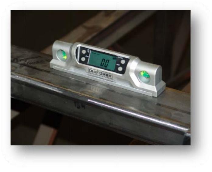
5. I Leveling your cross-member is an extremely critical step. Take the time here and do it right. Failure to follow this step correctly can result in poor handling, poor alignment properties, and unsafe driving characteristics. Begin by setting your level on the cross-member sitting left to right. Adjust the cross-member until it is level; this may require a little trimming to make fit.
Rev: A Installation Manual for Standard front steer IFS
Crossmember installation cont:
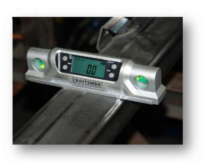
6. Place the level on the cross-member pointing front to back. As pointed out before, you will determine your ride stance. Whatever that ride stance may be, it is critical that the chassis is at that point now. Level the cross-member front to rear; this may require a little trimming to make fit.
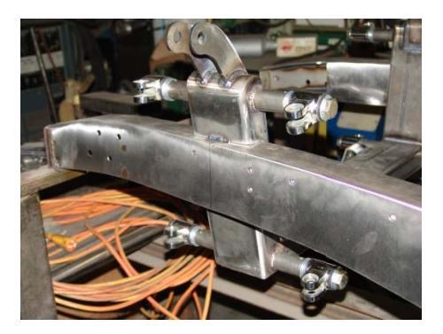
7. Tack the cross-member in place and double check your level. When you are satisfied with the fit and level, weld the cross-member into place.
Rev: A Installation Manual for Standard front steer IFS
A-Arm spindle assembly
Congratulations, the hard part is over. Now you will begin bolting all of the components together. Take time to lay your parts out and get familiar with them.
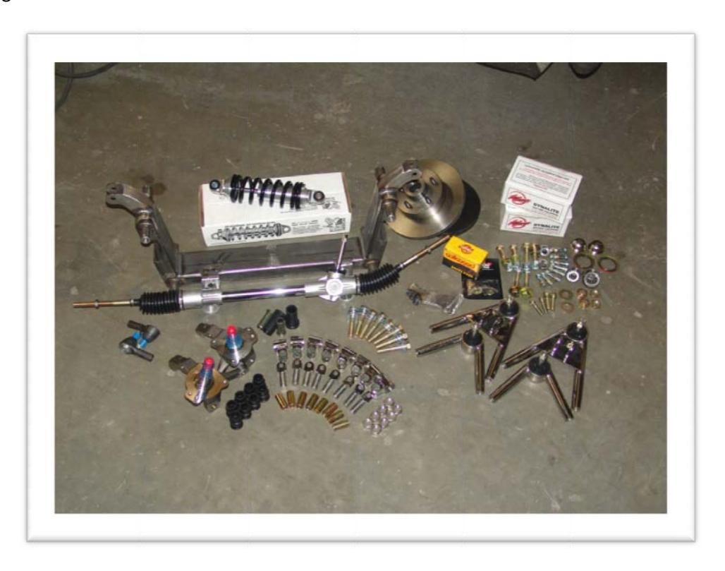
Remember; if any items appear to be missing immediately call our tech department.
1. Step one is to thread the rod ends into the a-arms. Before any step is taken an anti-seize compound MUST be used.
Rev: A Installation Manual for Standard front steer IFS
A-Arm spindle assembly cont
It is of utmost importance that the clevises be free of debris and that the a-arms are clear of any obstructions. Because of the tight tolerances necessary to achieve a precision fit, any amount of interference in the threads will cause the rod end and a-arm to bind; possibly resulting in irreparable damage to both pieces. To start you will need (8) rod ends and (8) ¾-16 jam nuts. Fully thread the jam nuts onto all (8) rod ends. Once that is done, insert the clevises into the a-arms. Thread the rod end all the way until it bottoms out. Next, back the rod end out a total of 5 turns. It is critical for alignment purposes that the rod ends be threaded into the a-arms identical amounts from left to right, top to bottom. Tighten the jam nuts (hand tighten only) to secure the rod ends in place. Repeat this step for all 8.
2. Step two is to assemble all 8 Stainless clevises and bolt them to the Crossmember. You will need (8) clevises with "Scotts" imprint, (8) bushing and sleeve packs, (32) 5/8" SAE washers, and (8) 5/8"-18x3-1/2" grade 8 yellow bolts. Insert (1) sleeve and (2) bushing halves into each clevis. Each clevis will also use 4 washers and 1 bolt.
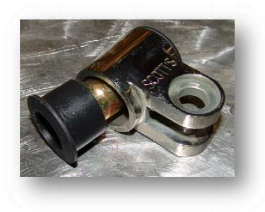
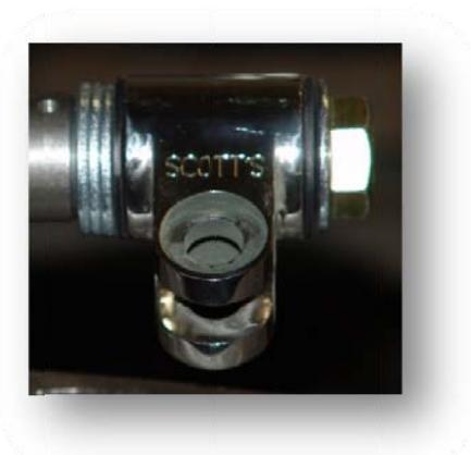
3. Starting with the bottom clevises, place a 5/8 bolt through each clevis (Scotts imprint facing up) using 1 washer under the bolt. With the bolt through the clevis, place 3 washers on the bolt. When you are done you should have each clevis sandwiched between 4 washers with 3 on the inside and 1 on the outside. Thread the bolt in to the Crossmember and torque to spec.
Rev: A Installation Manual for Standard front steer IFS
A-Arm spindle assembly cont
4. Join clevises to the rod ends (a-arms) next. You will need (8) ½" shoulder bolts, (24) ½" AN washers, (8) 3/8" nyloc nuts. Each joint will use (3) ½"AN washers, (1) shoulder bolt, and (1) nyloc. Beginning with the driver's side lower a-arm, hold it in place with the rod ends in the clevises. At this point it will most likely line up, however if it does not, you will need to thread the rod end in or out of the a-arm until it does. (VERY IMPORTANT) However many threads one rod end needs to move in or out, the same amount must be done for the second rod end. Once satisfied with the alignment place a ½" shoulder bolt in, place two AN washers on the top of the shoulder bolt, and one on the bottom under the nyloc. Do not tighten completely at this point. Repeat this step for all 4 a-arms.
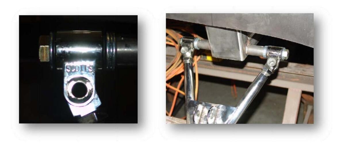
5. Next you will need (2) coilover shocks, (4) 5/8-18x3" grade 8 yellow bolts, (8) 5/8 grade 8 yellow washers, and (4) 5/8-18 nyloc nuts. Install the coilover shock into the upper shock mount using (1) 5/8 bolt, (2) 5/8 washers, and (1) 5/8 nyloc nut. After the upper mount is tightened, attach the shock to the lower a-arm using the same hardware as the upper mount.

Rev: A Installation Manual for Standard front steer IFS
A-Arm spindle assembly cont
6. To install the spindles you will need (2) spindles, one left, one right, (4) ball-joint castle nuts (these are still on the ball joints), (2) 3/16" ball-joint spacers, and (2) 3/8" ball-joint spacers. Because the lower a-arm is locked into place with the coil-over shock, placement of the spindle to the lower a-arm is made easy. Simply remove the ball joint nut and place the driver's side spindle onto the driver's side lower a-arm. Place the 3/8" ball joint spacer on the ball joint and place the ball joint nut back in place and tighten. Repeat this step for passenger side. The uppers arm is installed the same way into the spindle only you will use the 3/16 spacer rather than the 3/8.
Rack assembly will be the same whether your kit came with a power or manual rack. Although these examples show a power rack, you may have received a manual rack but still follow the instructions as written.
Rack components:
(1) Manual rack
- (2) Rack bushings & sleeves
- (2)5/8-18x3-1/2" grade 8 yellow bolts
- (2) 5/8" USS flat washers
- (2) 5/8" Nuts
- (2) Outer tie-rod ends
- (2) Rack extensions (optional)
If you are unsure whether or not you have these, check your packing slip.
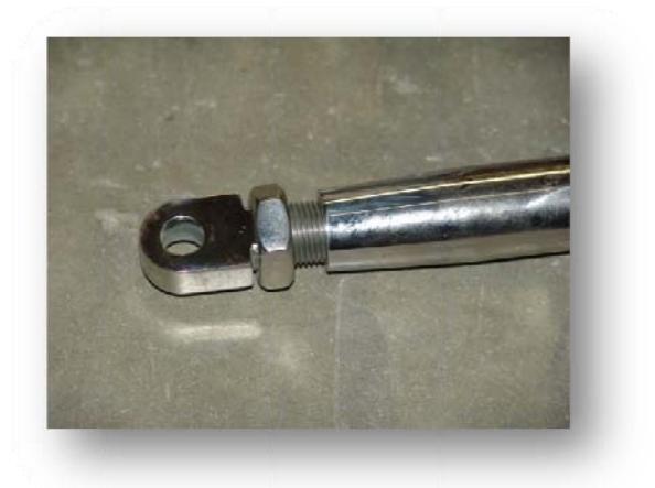
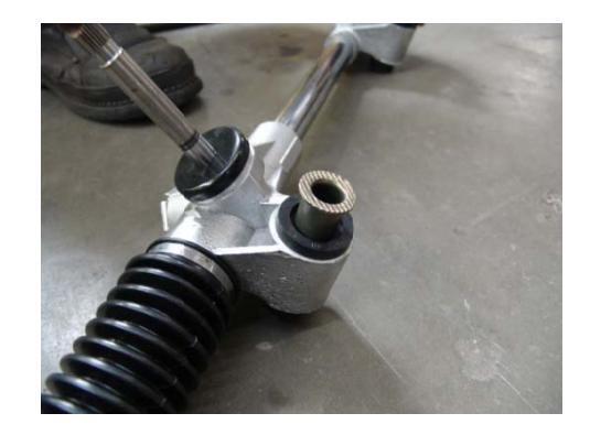
1. Begin by assembling your rack. Insert the Rack bushings and sleeves into the rack. (insert photo) Thread the out tie rod ends to the rack.
Rev: A Installation Manual for Standard front steer IFS
vww.scottshotrods.com
Rack Assembly cont
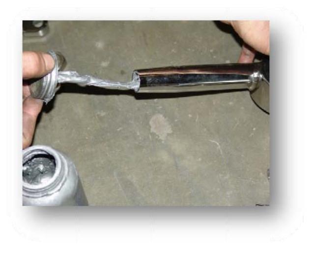
- 2. If you do not have rack extensions, skip this step. At the base of the rubber boot is a metal band clamp you will need to remove. Do not cut the boot. With the clamp removed, slide the boot up out of the way. Where the inner tie rod threads onto the rack is where the rack extension will be placed. Unthread the inner tie rod end, thread on the rack extension, then thread on the inner tie rod end to the extension. When finished you can use heavy duty tie wraps or band clamps to reattach the boot to the rack.
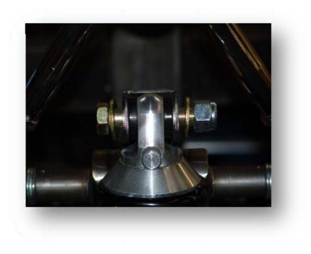
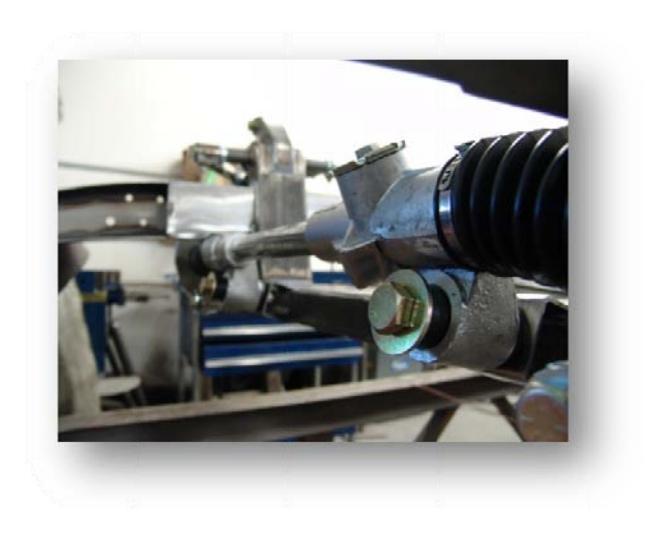
- 3. With the rack assembled you can now bolt it to the Crossmember. Hold the rack in place with the steering shaft pointing up and on the driver's side. Put a 5/8" washer onto a 5/8" bolt and place the rack in the mounts. Thread the 5/8" nuts onto the bolt from the backside of the mount. Tighten until snug, on the bushing sleeve. The bushing will "crush" a little, that is okay
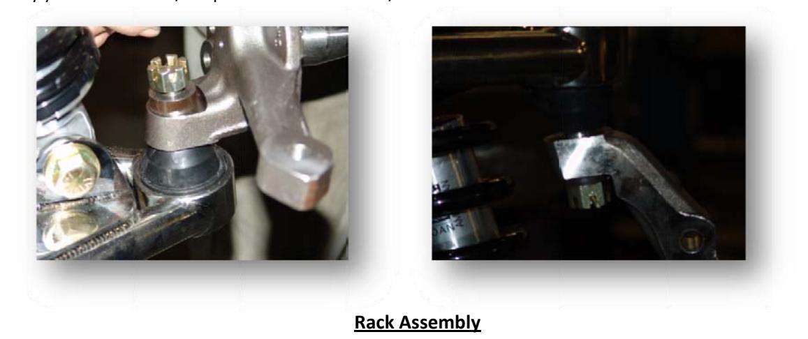
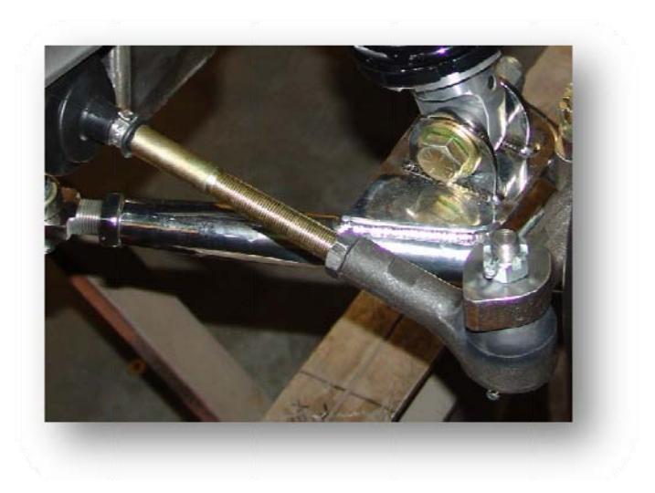
4. To bolt the rack to the spindles at this point, you only need to be "close". This will be adjusted during the alignment process. Start by holding the spindles as close to straight as possible. Thread in, or thread out the outer tie rod on until it lines up with the steering arm. Place the tie rod into the steering arm and secure with the castle nut. Do not tighten yet as this will need to come back off for alignment.
Your front end install is now complete. All that is left now is to assemble your brakes and optional sway bar. Please see those instructions to complete your installation.
Torque specs;
a-arm bolts 50-55
ball joints 55-60
crossmember screws tighten them up
rodend clevis 45-50
coilover shock bolts 50-55
rack bushings 40-45
rack extensions 40-45


 Loading...