


907254 - LM21SW

Walk Behind Lawn Mower
Owner/Operator & Parts Manual
Model
907254 - LM21SW
01185100 12/99
Printed in USA

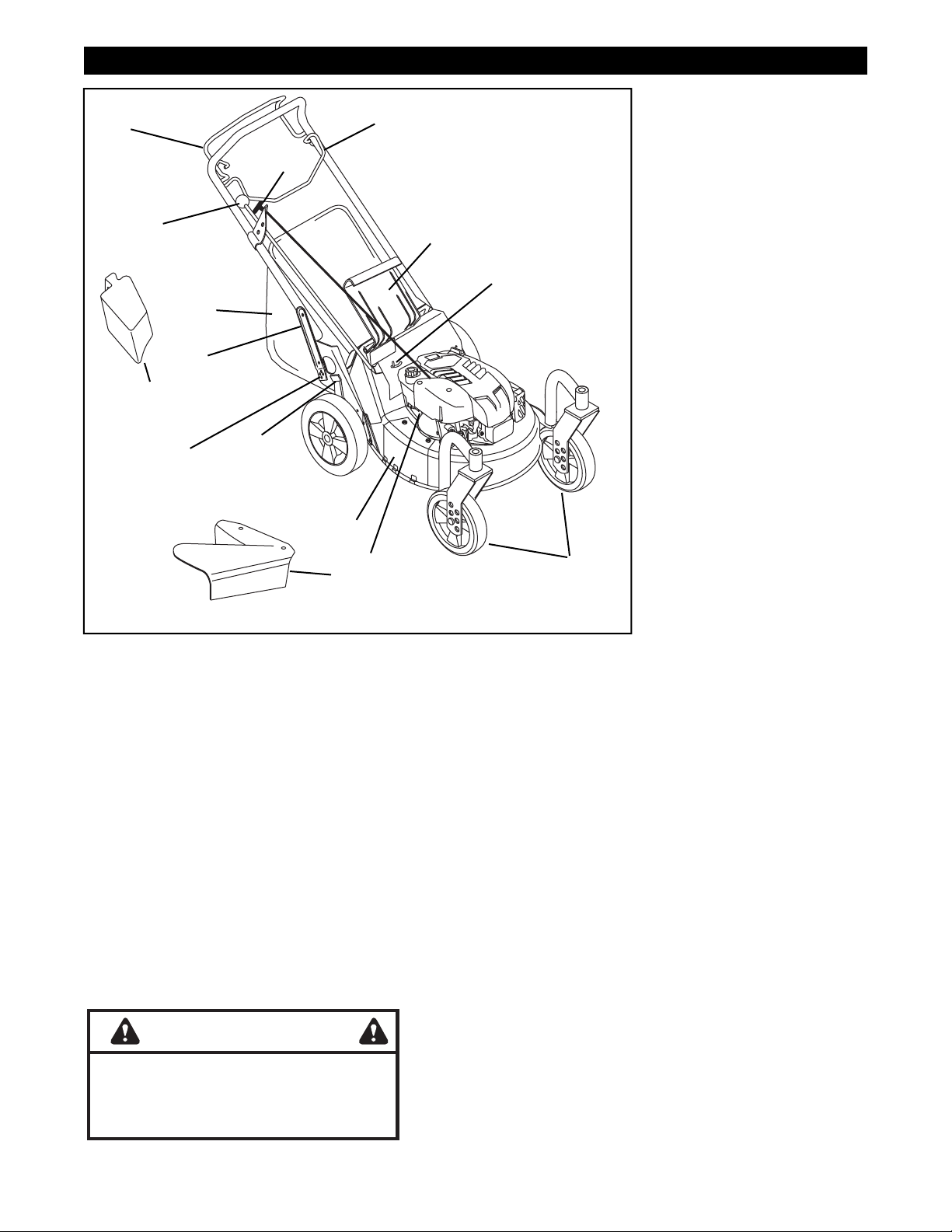
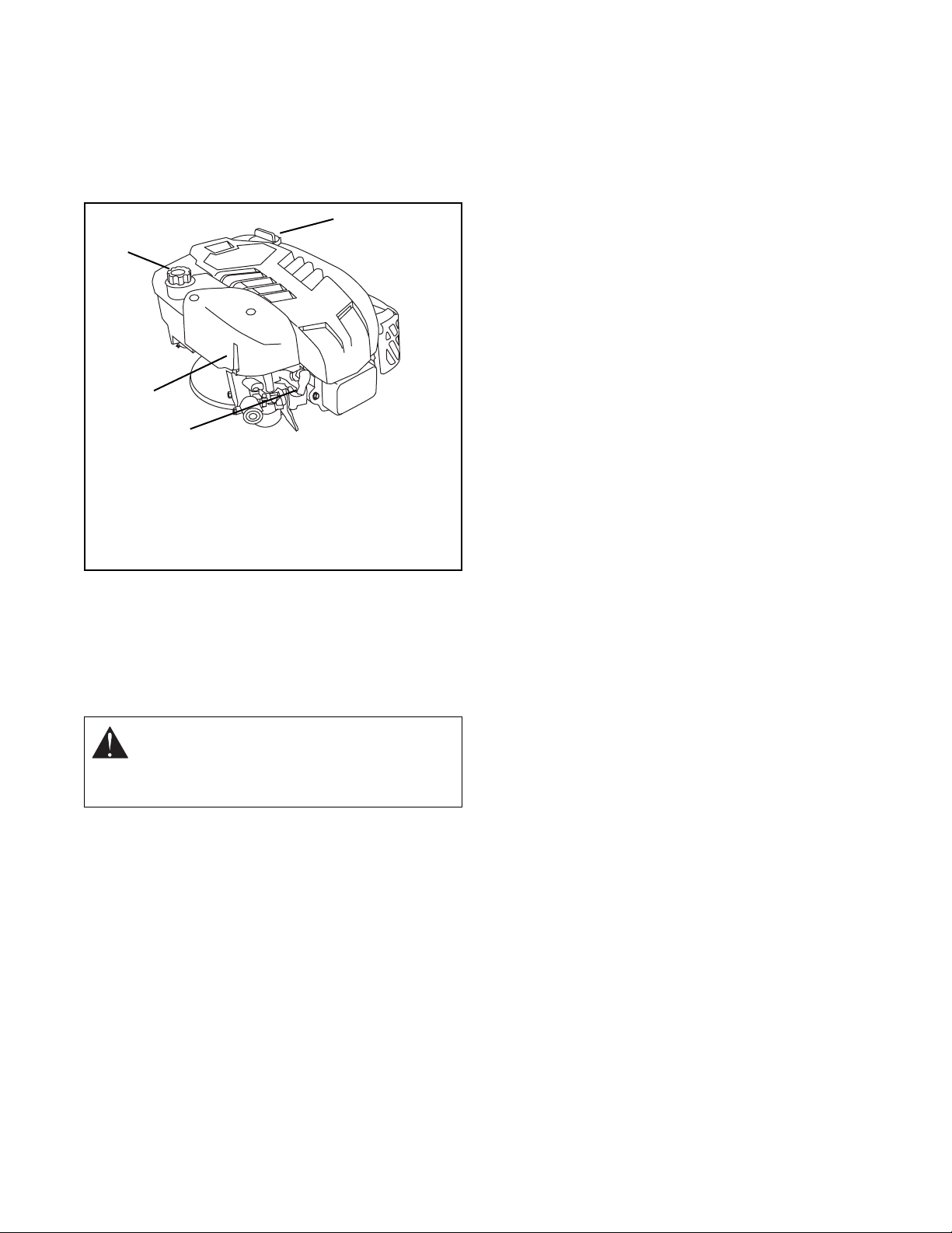
CONTROLS AND FEATURES
FRANÇAIS
11
12
1
10
2
9
8
13
6
4
3
5
7
14
15
OM0690
Figure 1
ENGLISH
1. Engine Control
2. Speed Selector (Selfpropelled)
3. Primer (Briggs Engine)
4. Side Discharge Cover
5. Side Discharge Deflector
6. Cutting Height Levers (2
Rear Wheel Adjusters, 2
Front Wheel Adjusters)
7. Rear Door
8. Adjustable and Folding
Handlebars
9. Grass Bag
10. Recoil
11. Wheel Drive Control
12. Mulch Plug
13. Handlebar Adjustment
Holes
14. Speed Indicator (Selfpropelled)
1. Commande moteur
2. Sélecteur de vitesse
3. Poire d’amorçage
4. Plaque de fermeture
latétale
5. Déflecteur de décharge
latérale
6. Leviers de hauteur de
coupe (réglage par les
roues)
7. Trappe arrière
8. Guidon réglable et pliable
9. Sac à herbe
10. Poignée du démarreur
manuel
11. Commande de
l’entraînement des roues
12. Déflecteur à paillis Mulch
13. Trous de réglage du
guidon
14. Indicateur de vitesse
ESPAÑOL
1. Control del motor
2. Selector de velocidad
3. Cebador
4. Cubierta de la descarga
lateral
5. Deflector de la descarga
lateral
6. Palancas de la altura de
corte (ajustadores de la
rueda)
7. Puerta trasera
8. Manillares ajustables y
plegables
9. Bolsa de recolección del
césped
10. Manilla de arranque de
retroceso
11. Control de la transmisión
de la rueda
12. Tapón Mulch
13. Agujeros para el ajuste
del manillar
14. Indicador de velocidad
WARNING
The engine exhaust from this product
contains chemicals known to the State
of California to cause cancer, birth
defects or other reproductive harm.
OL4030
3

4 5

E
TABLE OF CONTENTS
NGLISH
Controls and Features. . . . . . . . . . . . . . . . . . . . 3
Introduction . . . . . . . . . . . . . . . . . . . . . . . . . . . . 5
Safety . . . . . . . . . . . . . . . . . . . . . . . . . . . . . . . . . 6
Assembly . . . . . . . . . . . . . . . . . . . . . . . . . . . . . 10
Operation . . . . . . . . . . . . . . . . . . . . . . . . . . . . . 11
Maintenance . . . . . . . . . . . . . . . . . . . . . . . . . . . 15
INTRODUCTION
THE MANUAL
Before operation of unit, carefully and completely read
your manuals. The contents will provide you with an
understanding of safety instructions and controls
during normal operation and maintenance.
All reference to left, right, front, or rear are given from
the operation position, facing the direction of forward
travel.
SERVICE AND REPLACEMENT PARTS
When ordering replacement parts or making service
inquiries, know the Model and Serial numbers of your
unit and engine.
Numbers are located on the product registration form
in the unit literature package. They are also printed on
a serial number label, located on the frame of your unit
(Figure 2).
• Record Unit Model and Serial numbers here.
• Record Engine Model and Serial numbers here.
Service and Adjustments . . . . . . . . . . . . . . . . 18
Storage . . . . . . . . . . . . . . . . . . . . . . . . . . . . . . . 20
Troubleshooting . . . . . . . . . . . . . . . . . . . . . . . . 21
Specifications. . . . . . . . . . . . . . . . . . . . . . . . . . 21
Warranty . . . . . . . . . . . . . . . . . . . . . . . . . . . . . . . 22
Service Parts . . . . . . . . . . . . . . . . . . . . . . . . . . . 65
PRODUCT REGISTRATION
A warranty card must be filled out, signed, and returned
at time of purchase. This card activates the warranty.
Claims meeting requirements during limited warranty
period will be honored.
UNAUTHORIZED REPLACEMENT PARTS
Use only Ariens replacement parts. The replacement of
any part on this vehicle with anything other than an
Ariens authorized replacement part may adversely
affect the performance, durability, or safety of this unit
and may void the warranty. Scotts and Ariens disclaim
liability for any claims or damages, whether warranty,
property damage, personal injury or death arising out of
the use of unauthorized replacement parts.
DELIVERY
Customer Note: If you have purchased this product
without complete assembly and instruction by your
retailer, it is your responsibility to:
• Read and understand all assembly instructions in
this manual. If you do not understand or have
difficulty following the instructions, contact your
nearest Ariens Dealer for assistance. To locate
your nearest Ariens Dealer, call 1-877-466-0812.
Serial Number
Label
Figure 2
OM0650
WARNING: Improper assembly or
adjustments can cause serious injury.
• Do not operate the unit unless all controls
function as described in this manual. Before
attempting to operate your unit:
1. Make sure all assembly has been properly
completed.
2. Understand all Safety Precautions provided in
the manuals.
3. Review control functions and operation of the
unit.
4. Review recommended lubrications,
maintenance and adjustments.
5. Review Limited Warranty Policy.
6. Fill out Original Purchaser Registration Card
and return the card to Ariens Company.
DISCLAIMER
This product has been manufactured by Ariens. Scotts
and Ariens reserve the right to discontinue, make
changes to, and add improvements upon its products
at any time without public notice or obligation. The
descriptions and specifications contained in this
manual were in effect at printing. Equipment described
within this manual may be optional. Some illustrations
may not be applicable to your unit.
SAFETY
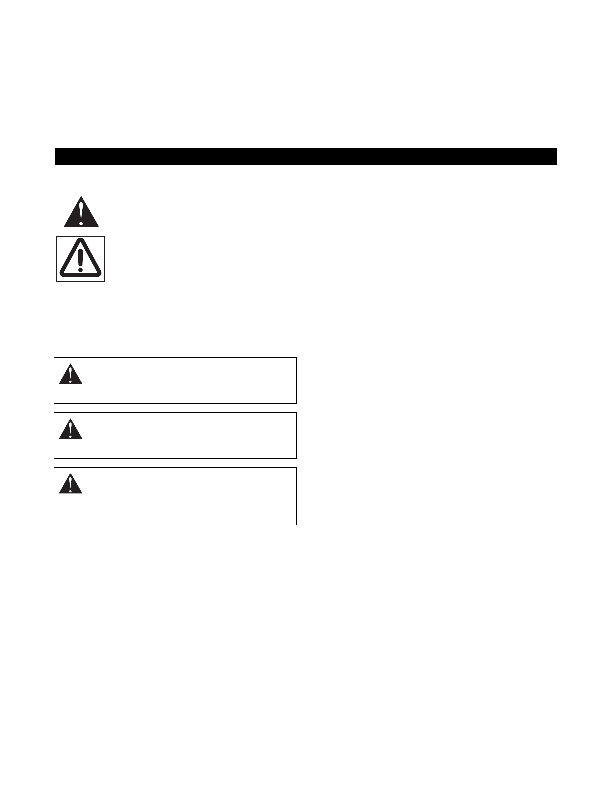
SAFETY ALERTS
Look for these symbols to point out
important safety precautions. They mean:
Attention!
Personal Safety Is Involved!
Become Alert!
Obey The Message!
The safety alert symbol is used in decals on the unit
and with proper operation procedures in this manual.
Understand the safety message. It contains important
information about personal safety on or near the unit.
DANGER: IMMINENTLY HAZARDOUS
SITUATION! If not avoided, WILL RESULT in
death or serious injury.
WARNING: POTENTIALLY HAZARDOUS
SITUATION! If not avoided, COULD RESULT
in death or serious injury.
PRACTICES AND LAWS
Practice usual and customary safe working
precautions, for the benefit of yourself and others.
Understand and follow all safety messages. Be alert to
unsafe conditions and the possibility of minor,
moderate, or serious injury or death. Learn applicable
rules and laws in your area.
REQUIRED OPERATOR TRAINING
Original purchaser of this unit was instructed by the
seller on safe and proper operation. If unit is to be used
by someone other than original purchaser; loaned,
rented or sold, ALWAYS provide this manual and any
needed safety training before operation.
CAUTION: POTENTIALLY HAZARDOUS
SITUATION! If not avoided, MAY RESULT in
minor or moderate injury. It may also be used
to alert against unsafe practices.
NOTATIONS
NOTE: General reference information for proper oper-
ation and maintenance practices.
IMPORTANT: Specific procedures or information
required to prevent damage to unit or attachment.
6
OL3030
OL4530
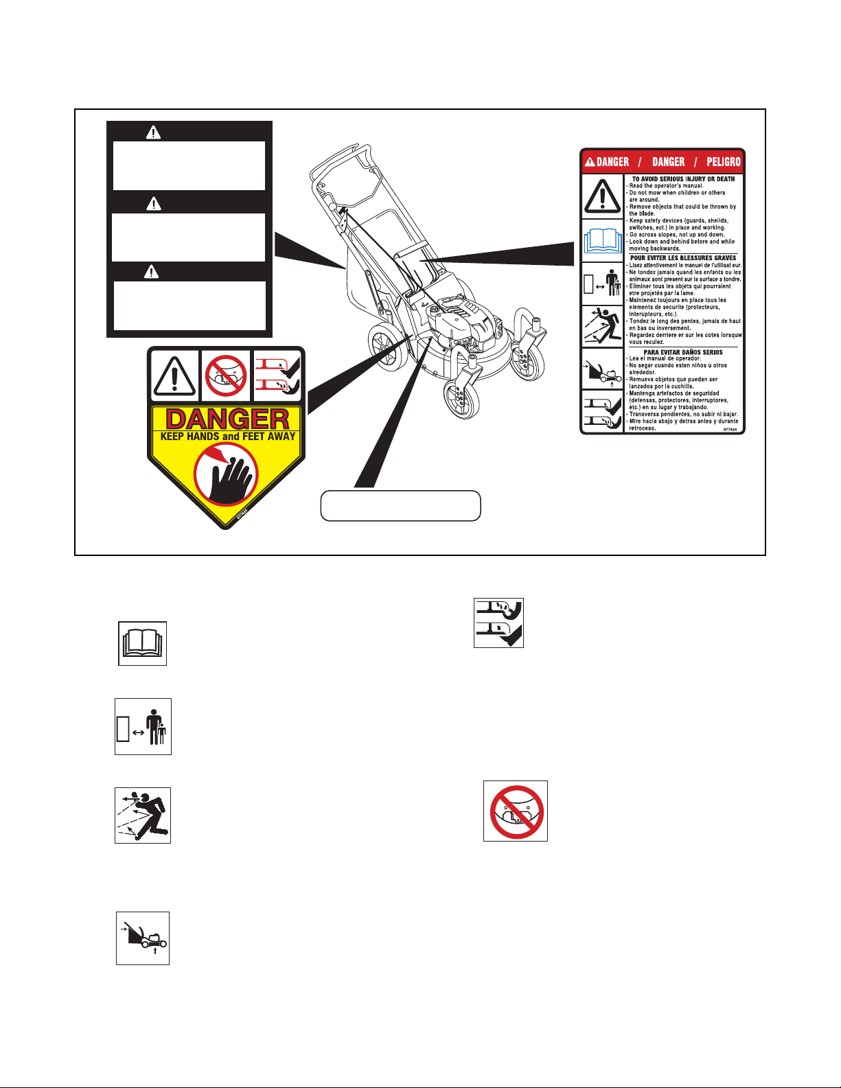
SAFETY DECALS AND LOCATIONS
ALWAYS replace missing or damaged Safety Decals.
Refer to Figure 3 for Safety Decal locations.
CAUTION
BAG IS SUBJECT TO WEAR AND
•
DETERIORATION.
CHECK BAG FEQUENTLY, REPLACE WHEN
•
NECESSARY.
USE ORIGINAL BAG TO COMPLY WITH SAFETY
•
SPECIFICATIONS.
PRECAUCION
LA BOLSA ESTA SUJETA A DESGASTE Y
•
DETERIORO.
REVISAR LA BOLSA FREQUENTAMENTE,
•
Y REEPLAZARLA SI ES NECESARIO.
USAR BOLSAS ORIGINAL PARA CUMPLIR CON
•
LAS ESPECIFICACIONES DE SEGURIDAD.
ATTENTION
LE SAC EST SOUMIS À L’USURE ET A LÀ
•
DÉTÉRIORATION.
VÉRIFIER LE SAC FRÉQUEMMENT. LE
•
REMPLACER AU BESOIN.
UTILISER UN BAC D’ORIGINE CONFORME
•
AUX NORME DE SECURITE.
3
1
1. DANGER
TO AVOID SERIOUS INJURY OR DEATH
OL1801
OL4370
OL0910
OL4540
2
MEETS C.P.S.C. BLADE
SAFETY REQUIREMENTS
Before operating unit, completely read
and understand all manuals provided.
Keep people and pets away when
operating unit. Keep children out of
the work area and under the watchful
care of a responsible adult.
Always stand clear of discharge area.
DO NOT direct discharge toward
other people. Remove objects that
could be thrown by the blade. DO
NOT operate mower over gravel and
hard surfaces.
DO NOT operate mower unless
guards are in operating position.
Figure 3
OM0660
ROTATING BLADE! Keep hands and
feet away.
• Go across slopes, not up and down.
• Look down and behind before and while moving
backwards.
2. DANGER
KEEP HANDS AND FEET AWAY
• Do not operate mower unless
guards are in operating position.
3. CAUTION!
• Bag is subject to wear and deterioration.
• Check bag frequently, replace when necessary.
• Use original bag to comply with safety
specifications.
7

SAFETY RULES
Operational
Inspect unit and work area before operation.
Clear work area of objects which might be picked up
and thrown. Remove all stones, sticks, wires, and other
foreign objects. Tall grass can hide obstacles.
Only Trained Adults may operate unit. Training includes
actual operation.
Keep equipment in good condition.
ALWAYS keep discharge cover in place.
NEVER operate the engine with the Rear Door open
unless the Grass Bag is in place.
When mulching, the Side Discharge Opening Cover
must be installed and the Rear Door fully closed
whenever the engine is operating.
DO NOT pull mower backwards unless absolutely
necessary. Look down and back before and while
moving backwards.
DO NOT start the engine or operate mower unless
either the Side Discharge Opening Cover or the Side
Discharge Deflector is installed.
Keep the area of operation clear of all persons, children
and pets.
ALWAYS clear area before operation to avoid thrown
objects.
Stop mower if anyone enters the area.
Keep safety devices or guards in place and functioning
properly. NEVER modify or remove safety devices.
ALWAYS keep hands away from all rotating parts
during operation.
Do not put hands or feet near or under rotating parts.
Keep clear of the discharge opening and mower pan at
all times. NEVER open the Rear Door without the
Grass Bag in place when the engine is operating.
ALWAYS keep feet and hands away from all rotating
parts during operation. Rotating parts can cut off body
parts.
DO NOT mow at too fast a rate. DO NOT change
engine governor setting or over-speed the engine.
ALWAYS operate unit when there is good visibility and
light.
Use extra care when approaching blind corners,
shrubs, trees, or other objects which may obscure
vision.
ALWAYS be sure of your footing.
Do not operate mower in wet grass. Always be sure of
your footing. Keep a firm hold on handlebar. Walk,
never run.
If equipment vibrates abnormally, stop engine at once,
wait for moving parts to stop and remove wire from
spark plug. Repair any damage before restarting unit.
Avoid uneven work areas and any rough terrain.
Be familiar with area of operation. Stay alert for holes,
rocks, roots, and hidden hazards in area of operation.
Keep away from drop-offs, ditches or embankments.
Operator could lose footing or balance.
DO NOT operate on steep slopes.
NEVER leave unit unattended on a slope. Chock
wheels if parking on a slope.
Mow across the face of slopes, never up and down. Be
especially cautious when changing direction on slopes.
Remove the key when parking.
Take all possible precautions when leaving unit
unattended.
ALWAYS shut off engine and remove spark plug wire to
prevent accidental starting or unauthorized use.
Personal
Keep children out of work area and under the watchful
care of an adult.
NEVER allow children to operate mower.
Turn the mower off if children enter the area.
NEVER direct discharge toward bystanders. The
operator is responsible for the safety of bystanders.
Wear adequate safety gear, protective gloves and
footwear.
Wear sturdy footwear. DO NOT operate mower
barefoot or when wearing open sandals or canvas
shoes.
Always wear safety goggles or safety glasses with side
shields when operating mower.
NEVER wear loose clothing, jewelry or long hair that
may get caught in rotating parts. Protect eyes, face and
head from objects that may be thrown from unit.
NEVER operate after or during the use of medication,
drugs or alcohol. Complete and unimpaired attention is
required when operating unit.
ALWAYS stand clear of discharge when operating unit.
Do not operate mower on gravel or on loose material
such as sand. Stop mower when crossing gravel
drives, walks, or roads. Objects may be picked up and
thrown, causing damage or injury.
DO NOT touch parts which are hot. Allow parts to cool.
Moving parts can cut or amputate fingers or a hand.
Wrap blade(s) or wear gloves to service.
ALWAYS keep hands away from all pinch points.
Fumes from the engine exhaust can cause death or
serious injury. DO NOT run engine in an enclosed
area.
8

Service and Adjustments
NEVER attempt to make any adjustments to unit while
engine is running. Stop engine and wait for all moving
parts to stop before servicing (except where
specifically recommended).
DO NOT make cutting height wheel adjustments while
the engine is running.
On self-propelled models, the wheel drive control will
cause the forward movement of the mower to stop. If
this feature fails to operate, disconnect spark plug wire
and repair before using unit. Wheel drive must be
disengaged when starting engine.
Fuel is highly flammable and its vapors can explode.
ONLY use approved fuel containers.
• NO Smoking!
• NO Sparks!
• NO Flames!
• Allow engine to cool before filling fuel tank.
Check fuel supply before starting engine.
DO NOT fill gasoline tank indoors, when engine is
running, or while engine is still hot.
Allow engine to cool several minutes before removing
fuel cap.
Replace gasoline tank cap securely and clean up any
spilled fuel before starting engine.
Stop engine, wait for moving parts to stop, remove
ignition wire and secure away from spark plug before
attempting to: unclog, repair, adjust, inspect or clean
unit.
To reduce fire hazard and overheating, keep equipment
free of grass, leaves, debris or excessive lubricants.
Maintenance
Follow engine manufacturer’s safety instructions when
servicing engine.
Keep all nuts, bolts, and screws tight and be sure
equipment is in safe working condition. Check all
hardware at regular intervals, especially blade
attachment bolts.
Use only replacement parts designed for your unit. See
your Ariens Dealer.
Worn out mufflers are more than just a noise nuisance
and should be replaced immediately. Continued use
could result in fire or explosion.
ALWAYS block wheels and know all jack stands are
strong and secure and will hold weight of unit during
maintenance.
Check grass bag for wear, damage, and/or
deterioration. Replace only with Ariens original
equipment replacement part for safety.
Storage
Allow engine to cool before storing in any enclosure.
Refer to Storage Section of this Owner’s Manual for
important instructions if unit is to be stored for
extended periods.
ALWAYS clean unit before extended storage. See
engine manual for proper storage.
DO NOT store unit inside a building with fuel in the fuel
tank where any ignition sources are present.
Safety Interlock System
Engine/Blade Control feature on mower will cause
engine and blade to stop whenever operator releases
control on handlebar. If feature fails to operate,
disconnect spark plug wire and adjust or have it
repaired before using unit.
Accessories
Use only accessories which have been approved by
Ariens and are properly installed.
Spark Arrestor
This product is equipped with an internal combustion
engine. DO NOT use on or near any unimproved, forest
or brush covered land unless the exhaust system is
equipped with a spark arrestor meeting applicable
local, state or federal laws. A spark arrestor, if used,
must be maintained in effective working order by the
operator. See your Ariens Dealer or engine
manufacturer’s service center.
9
TO REMOVE UNIT FROM CARTON
1. Cut off top of carton.
2. Remove front and rear inserts and literature pack.
3. Cut out back of carton and roll unit out.
4. Remove protective packaging materials.
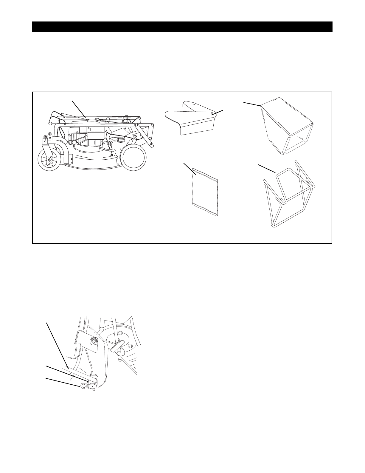
ASSEMBLY
1
OM0700
1. Mower Unit
2. Discharge Chute
3. Grass Bag
4. Grass Bag Frame
5. Literature Pack
ASSEMBLY
1. Unfold and adjust handlebar.
2. The Speed Selector rod is shipped on the
handlebar with hardware in position. Remove hair
pin, insert bent end of rod through hole in swivel
of speed control bell crank, and retain with hair
pin.
5
Figure 4
3
2
OM0340
OM0320
4
Literature
Pack
OM0350
OM0330
3. Assemble grass bag onto bag frame.
4. Configure mower for bagging, side discharge or
mulching. See Mower Configurations in
Operation Section.
5. Check the Engine/Blade Control feature. Engine
and blade must stop within 3 seconds whenever
control handlebar is released.
6. Fill fuel tank. See Operation Section.
1
3
2
1. Speed Selector Rod
2. Hair pin
3. Speed Control Bell
Crank
OM0300
Figure 5
10
OPERATION
CONTROLS AND FEATURES
See Figures 1 and 6 for Controls and Features.
Engine/Blade Control
WARNING: DO NOT attempt to start your
engine at this time. Familiarize yourself with
controls to see what they do and how they
work. Thoroughly read and understand entire
Operators Manual first.
CAUTION: Check function of Engine/Blade
Control regularly. Improper function of control
could cause injury.
The Engine Control must be held
against the handlebar in order to start
the engine as well as during mowing
operations to keep the engine running.
Releasing the control during operation stops the
engine and blade.
Handlebar
Handlebar adjusts to four positions by selecting holes
in braces. Select a safe, comfortable height and place
pin through hole in brace that is closest to that height.
Refer to Adjustment Section for instructions.
Recoil Starter Handle
When pulled, handle will turn engine over.
OM0450
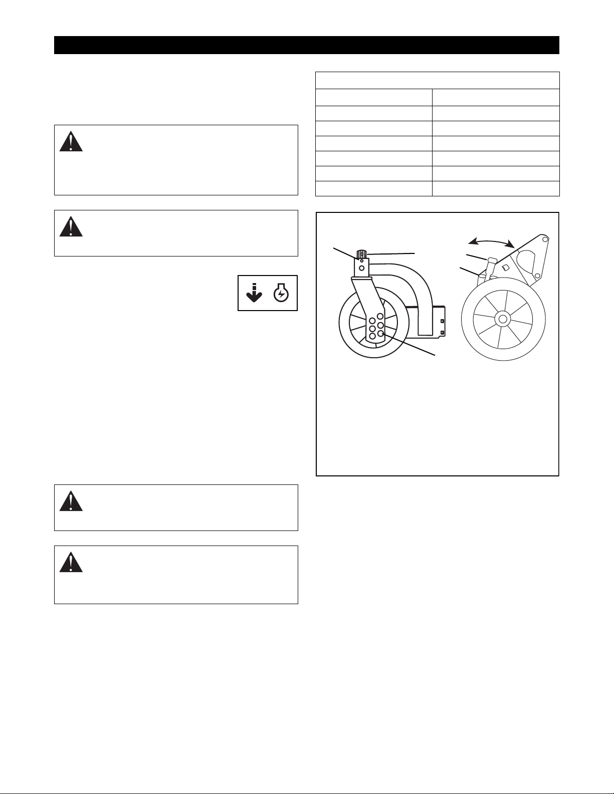
Cutting Height Settings Chart
Notch Cut grass length
LOW
2
3
4
5
HIGH
4
5
3
Front Swivel
OM0180
1. Cutting Height Lever
2. Notches
3. Clevis Pin & Swivel Height Adjustment Holes
4. Swivel Lock Hole (Swivel Locked)
5. Linchpin Storage Hole (Free)
1" (25 mm)
1-3/8" (35 mm)
1-3/4" (45 mm)
2-1/4" (57 mm)
2-3/4" (70 mm)
3-1/4" (83 mm)
Low
1
2
High
Rear
OM0190
Cutting Height – Standard Models
DANGER: To avoid inadvertent blade contact,
NEVER attempt to make any cutting height
adjustment while engine is running.
CAUTION: On self-propelled models, both
rear wheels must be positioned at same
height or traction drive may not clutch or
operate properly.
To change cutting height, move cutting height levers
one notch at a time on each wheel until desired height
of cut is obtained. (Figure 6)
NOTE: Each Wheel on mower must be set at the same
height for a level cut.
Figure 6
11
OPTIONAL CONTROLS
See Figures 1 and 6.
Cutting Height – Swivel Models
CAUTION: On swivel wheel models, when
mowing on slopes it is recommended that the
linchpin be positioned through the swivel lock
hole. If wheels are in the swivel position and
control handles are released the mower may
“free roll” downhill. Never mow on steep
slopes.
To change front wheel cutting height, insert clevis pin
into the holes that correspond to the desired cutting
height. (Figure 6).
To change rear wheel cutting height, move cutting
height levers one notch at a time until the desired
cutting height is obtained. (Figure 6).
Primer Bulb (Briggs & Stratton Engine)
Push the Primer Bulb in to add fuel for easier engine
start.
With Speed Selector set at a slow travel speed and
engine running, engage Wheel Drive Control. Increase
speed with Speed Selector to a safe, comfortable
walking pace. Once speed has been selected, Speed
Selector should remain in this position. If not, adjust
speed control bell crank spring tension. (See
Adjustments ).
Wheel Drive Control
CAUTION: Holding Wheel Drive control of
self-propelled models against handlebar,
when attempting to start mower, will propel
mower forward.
With engine running, slowly squeeze and hold Wheel
Drive Control against handlebar to propel mower
forward. Release Wheel Drive Control to stop forward
motion.
PRE-START
CAUTION: Make sure all hardware is tight, all
safety devices in place and all adjustments
made correctly.
Primer Bulb
OM0200
Figure 7
Speed Selector
Speed Selector is used to select variable forward travel
speeds of mower.
High –Push selector all the way forward.
Low –Pull selector all the way rearward.
OM0480
1. Check that engine crankcase oil is at proper level.
Fill or change engine oil as required.
2. Check air cleaner for dirt. Clean as required.
3. Check hardware and safety devices.
FILLING FUEL TANK
WARNING: EXPLOSIVE VAPORS and
FLAMMABLE FUEL can result in serious
injury or death. Handle fuel with care.
ALWAYS use an approved fuel container.
No Smoking! No Lighted Materials!
No Open Flame!
Allow engine to cool before maintenance.
Gasoline is highly flammable and must be
handled with care. Allow engine to cool
several minutes before removing fuel tank
cap. Never fill tank when engine is running or
is hot from operation. DO NOT allow open
flame, matches, or smoking in area. DO NOT
overfill. Allow about 1/4" of tank space for fuel
expansion. Wipe up any spills and allow
vapors to dissipate before starting engine.
Use approved (Red) gasoline container.
To add fuel to Fuel Tank:
1. Put unit in open or well-ventilated area.
2. Stop engine and allow to cool.
12
3. Clean Fuel Cap and surrounding area to prevent
dust, dirt and debris from entering Fuel Tank.
4. Remove Cap.
IMPORTANT: DO NOT use gasohol or gasoline
containing alcohol because alcohol will cause internal
parts to deteriorate. See Engine Manual for correct
type and grade of fuel.
5. Fill fuel tank. (See Specifications for tank
capacity.)
6. Replace Fuel Cap and tighten.
7. ALWAYS clean up any spilled fuel.
Mower Configurations
CAUTION: DO NOT operate mower unless
either side discharge opening cover or side
discharge deflector is installed. Objects may
be picked up and thrown causing damage or
personal injury. Never operate engine with
rear door open unless grass bag is in place.
To configure your mower for bagging, side discharge or
mulching, proceed as follows:
Bagging: Lift rear door, place bar of grass bag frame
on lip of mounting flange and lower rear door. If
necessary, lift rear of grass bag frame to lock in
position.
Be sure there are no openings between bag and
mounting surface after installing bag. If necessary clear
bag mounting surface of debris.
To remove grass bag, lift rear door. Then with handle,
lift bag up off mounting flange and close rear door.
CAUTION: Objects may be thrown. Check
grass bag frequently for wear or deterioration.
Replace worn or damaged bag with Ariens
original equipment replacement bag only.
Mulching: Remove grass bag and install side
discharge opening cover. Open rear door and insert
Mulchmaster Plug with the beveled face to the left.
Rear door should close flush.
STOPPING IN AN EMERGENCY
To stop the mower in an emergency situation, release
both the engine/blade control bail and the wheel drive
control bail from the handlebar. Allow all moving parts
to stop before leaving operator’s position.
STARTING AND SHUT OFF
See Figures 1, 4 and 5 for all Controls and Features.
NOTE: Start engine on a hard level surface that is free
of debris.
Manual Start
1. For engines with a primer, push primer bulb 2 or 3
times for a cold engine.
2. With engine/blade control held against the
handlebar, grasp starter handle and pull rope out
slowly until it pulls harder. This is the compression
stroke. Let rope rewind slowly. Then pull rope with
rapid continuous full arm stroke to start engine.
Allow rope to rewind slowly.
IMPORTANT: DO NOT let starter handle snap against
engine.
3. Repeat until engine starts. (If engine does not
start, refer to Troubleshooting .)
Shut Off
1. On self-propelled models, release wheel drive
control and allow unit to come to a complete stop.
2. Release engine/blade control, and allow engine
to cool.
Side Discharge: With grass bag removed, remove two
lock nuts and washers that secure side discharge
opening cover to mower. Lift cover to free tabs from
slots and remove cover from mower.
Position holes in side discharge deflector over studs on
mower. Place tab on rear edge of deflector onto edge
of discharge opening. Secure deflector with cover
hardware.
WARNING: NEVER direct discharge of
material toward bystanders. Do not allow
anyone near equipment while unit is in
operation.
13

Mowing Tips
CAUTION: On swivel wheel models, when
mowing on slopes it is recommended that the
linchpin be positioned through the swivel lock
hole. If wheels are in the swivel position and
control handles are released the mower may
“free roll” downhill. Never mow on steep
slopes.
CAUTION: If clog or obstruction prevents
grass flow, release Engine/Blade Control and
disconnect spark plug wire before attempting
to clear away any clogs.
The following tips will help you to mow safely, achieve
maximum performance from your mower and maintain
the appearance of your lawn.
When bagging, be sure to release Engine/Blade
Control to stop engine and blade before attempting to
remove and empty grass bag. Empty bag before it
becomes overloaded and clogs mower.
Restarting engine will be easier if mower is allowed to
completely discharge clippings before stopping engine.
NOTE: Be sure to empty grass bag and clean mower
pan after each use. DO NOT allow grass clumps or a
coating of grass and debris to collect inside of grass
bag or mower pan.
NOTE: Avoid operating over bare ground with only
patches of grass. This causes dirt and grass to collect
under pan surface and in grass bag.
Prevent debris buildup and allow proper air circulation.
Remove grass bag from mower, wash bag with hose
and allow to dry.
Mulching Tips
For best mulching performance, set mower height to 3
inches. If grass is very tall, do not cut more than 1 inch
of grass per cutting.
Cut grass only when dry, not when it is wet from dew,
rain, or watering. Wet grass tends to pack inside the
mower pan. If cut grass does not disperse evenly, it is
probably because too much grass is being removed
per cutting, the grass is too wet, or the travel speed is
too fast.
14

MAINTENANCE
Ariens Dealers will provide any service, parts or
adjustments which may be required to keep your unit
operating at peak efficiency. Should engine service be
required, contact an Ariens dealer or an authorized
engine manufacturer's service center.
MAINTENANCE SCHEDULE
The chart shows the recommended maintenance
schedule that should be performed on a regular basis.
More frequent service may be required due to working
conditions (heavy loads, high ambient temperatures,
dusty conditions, or airborne debris).
See Engine Manual for further maintenance and
troubleshooting information.
MAINTENANCE SCHEDULE
Service Performed
Check Air Cleaner
Check Engine Oil
Check Mower Blade
Check Drive Belt
Check Engine/Blade
Control
Check Grass Bag
Check Drive Control
Daily 25 50 100
•
•
*
•
•
•
•
•
•
WARNING: Stop engine, wait for moving
parts to stop, and remove wire from spark
plug (keep wire away from plug to prevent
accidental starting) before attempting any
lubrication or maintenance procedures.
CAUTION: DO NOT touch engine parts which
are hot from operation. Allow parts to cool
before servicing.
CHECK AIR CLEANER (Briggs & Stratton
Engine)
See engine manual for specific information.
CHECK ENGINE OIL
IMPORTANT: Change engine crankcase oil after first
two (2) hours of operation. Thereafter, change oil every
twenty five hours of operation (more often in dusty, dirty
conditions). Refer to Engine Manual for oil type and
grade and detailed instructions.
Engine Oil Check and Change
The engine crankcase oil should be checked daily or
every five (5) hours of operation. Oil level MUST be
maintained in safe operating range on dipstick at all
times or engine damage will result.
IMPORTANT: DO NOT overfill. Be sure engine is level
when adding oil.
See Engine Manual for detailed instructions.
General Lubrication
Check Fasteners
Check Spark Plug
Check Engine Cooling
Check Muffler
After first 2 Hours of operation
*
WARNING: ROTATING PARTS can cut off
body parts. Keep hands and feet away. Loose
clothing, long hair or scarves can get caught
in rotating parts and cause death or serious
injury.
•
•
•
•
•
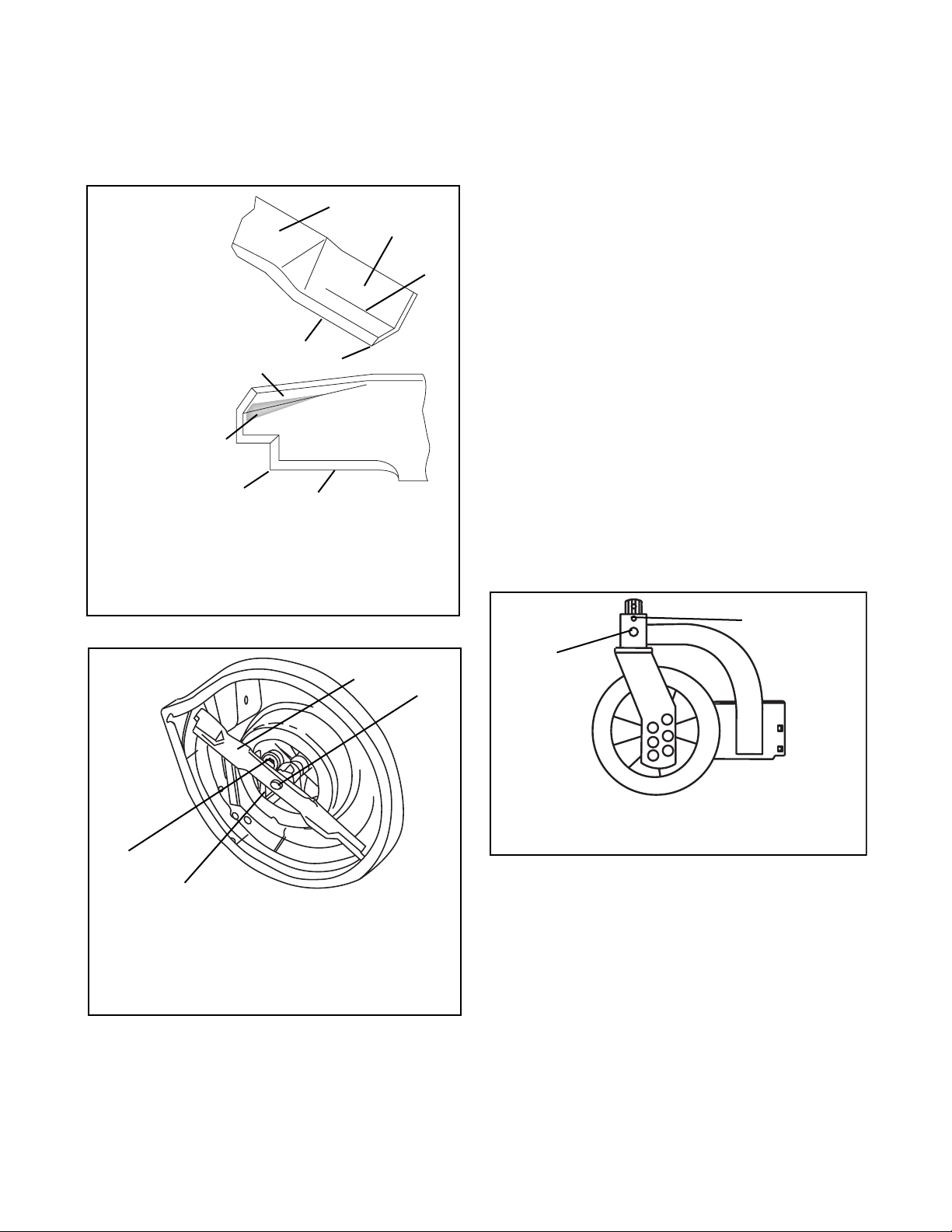
CHECK MOWER BLADE
See figures 10 and 11.
Regularly check mower blades for wear and that lock
washer is fully compressed by cap screw (requires
25-30 ft. lbs. of torque on cap screw).
When blade needs sharpening:
1. Block blade to prevent rotation.
2. Remove cap screw, lock washer and blade from
shaft.
3. Sharpen both ends of blade at original angle
(25°), removing equal amounts of material from
each end to maintain proper blade balance. New
blades are balanced to within 1.3 in. oz. at
factory. DO NOT grind around corner at tip of
blade. If cutting edge of blade cannot be
sharpened in a straight line to within 1/8 of an
inch of its end, replace blade with Ariens
replacement blade only.
15
4. Install blade, lock washer and tighten cap screw
until lock washer is fully compressed (requires
25-30 ft. lbs. of torque on nuts).
IMPORTANT: If mower is used under sandy soil
conditions, replace blades when air lifts become
eroded.
5
4
CHECK ENGINE/BLADE CONTROL
The engine/blade control must stop the engine and
blade within 3 seconds after the bail is released. If the
engine or blade continues to run, adjust or repair
control immediately. See Adjustments.
CHECK GRASS BAG
Check bag for wear or damage. Keep bag clean and
dry. Replace only with Ariens original equipment
replacement bag.
Mulching Blade
4
Standard Blade
3
2
1. Cutting Edge
2. Square Corner
3. Air Lift Erosion
4. Air Lift
Figure 10
CHECK DRIVE BELT
1
2
1
5. Reverse Lift
1
3
OM0230
OM0240
2
CHECK DRIVE CONTROL
Check operation of drive control. The drive must
disengage completely when the bail handle is
released. Adjust bail travel if necessary. See
Adjustments.
GENERAL LUBRICATION
Mower does not require any lubrication. Wheel
assemblies are designed for long life without additional
lubrication.
Swivel Lubrication (swivel units)
See Figure 12.
NOTE: Linchpin must be in the swivel lock hole while
lubricating.
2
1
4
3
1. Blade
2. Cap Screw, Lock Washer & Flat Washer
3. Drive Belt
4. Idler
OM0250
Figure 11
Check drive belt for wear or damage. Replace belt if
worn or damaged. See Service and Adjustments.
OM0180
1. Grease Fitting 2. Swivel Lock Hole
Figure 12
CHECK FASTENERS
Check all fasteners for proper tightness. Pay special
attention to blade hardware and all guards, shields and
safety devices.
CHECK SPARK PLUG
Spark plug should be cleaned (or replaced) if
necessary and gap reset to .030" every 100 hours of
operation or yearly, whichever comes first.
To clean:
1. Remove debris from area around spark plug
base.
2. Remove spark plug from engine.
16
3. Scrape and wash spark plug with a commercial
solvent. DO NOT blast clean.
4. Replace spark plug.
NOTE: Sparking can occur if wire terminal does not fit
firmly on spark plug. Replace terminal if damaged.
1
4
2
3
OM0680
Briggs & Stratton Intek OHV
1. Oil Fill Cap & Dipstick
2. Air Cleaner
3. Spark Plug & Wire
4. Fuel Cap & Tank
Figure 13
CHECK ENGINE COOLING
Engine is air cooled. Air must circulate freely around
engine from Air Intake to cooling fins on cylinder head
and block to prevent overheating.
WARNING: HOT SURFACES can cause
death or serious injury. DO NOT TOUCH parts
which are hot from operation. ALWAYS allow
parts to cool.
Every 100 hours of operation or yearly (more often if
conditions require) remove cooling shrouds and clean
cooling fins. Clean external surfaces of engine of dust,
dirt and oil deposits which can contribute to improper
cooling.
IMPORTANT: DO NOT operate engine with blower
housing removed or engine overheating damage will
result.
CHECK MUFFLER
Check muffler for cracks, wear, or other damage. Worn
out mufflers should be replaced immediately.
Continued use could result in fire or explosion.
17
1. Hole No. 1
2. Hole No. 2
3. Hole No. 3
4. Hole No. 4
5. Pin
6. Brace
7. Storage Position
Figure 15
4
1
2
3
5
6
7
OM0271
SERVICE AND ADJUSTMENTS
SERVICE POSITION
WARNING: ACCIDENTAL ENGINE START
UP can cause death or serious injury.
ALWAYS stop engine, wait for moving parts to
stop and remove wire from spark plug before
adjusting or servicing.
Place unit on a flat level surface. ALWAYS stop engine.
Assure unit is secure and will not tip over. Strap and
clamp onto bench if needed.
CAUTION: Before unit is tipped up, remove
enough fuel so that no spills will occur. A
piece of plastic bag may be used to seal fuel
tank opening when tipping mower. To seal,
remove fuel tank cap, cover fuel tank opening
with plastic, replace and tighten cap securely
before attempting to tip mower. Be sure to
remove plastic before attempting to operate
mower.
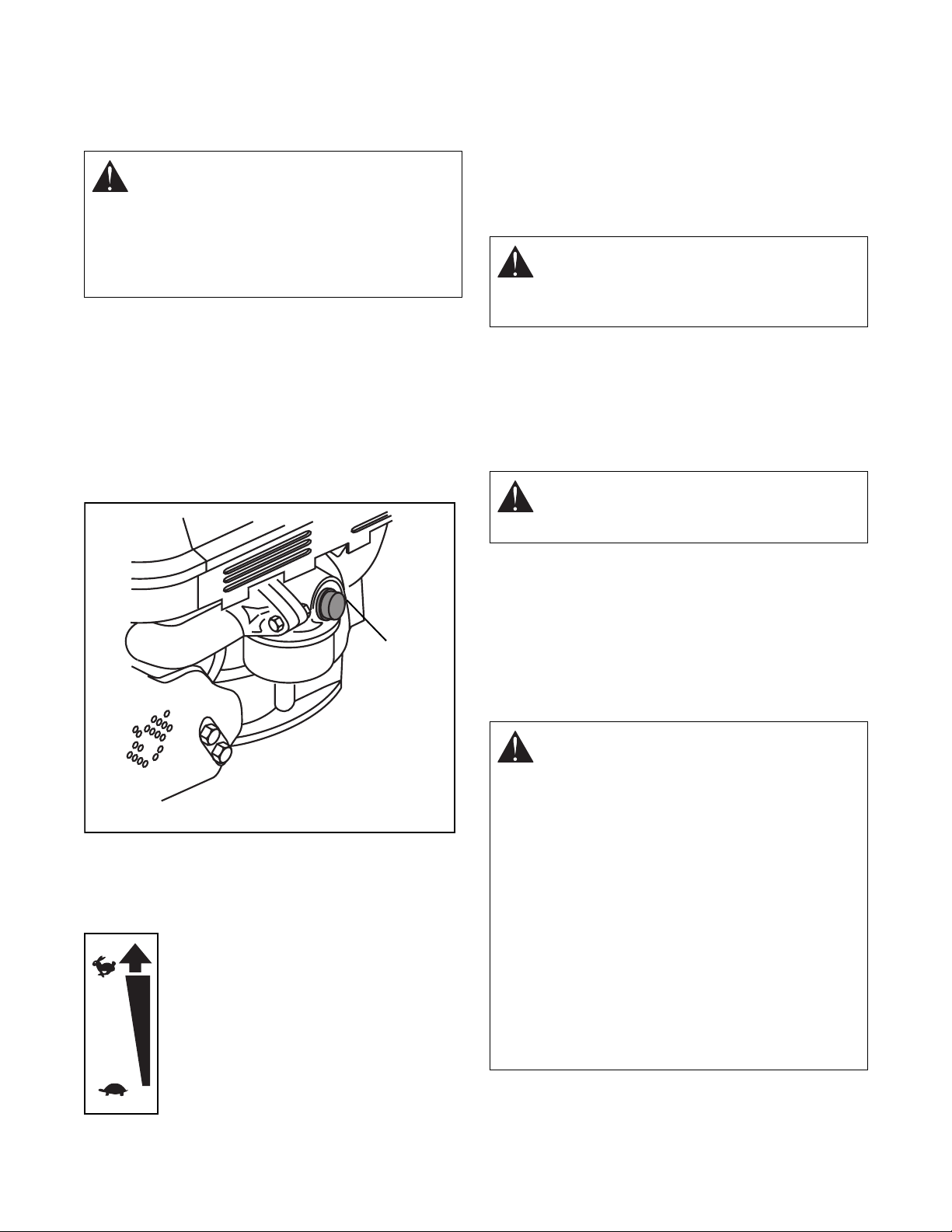
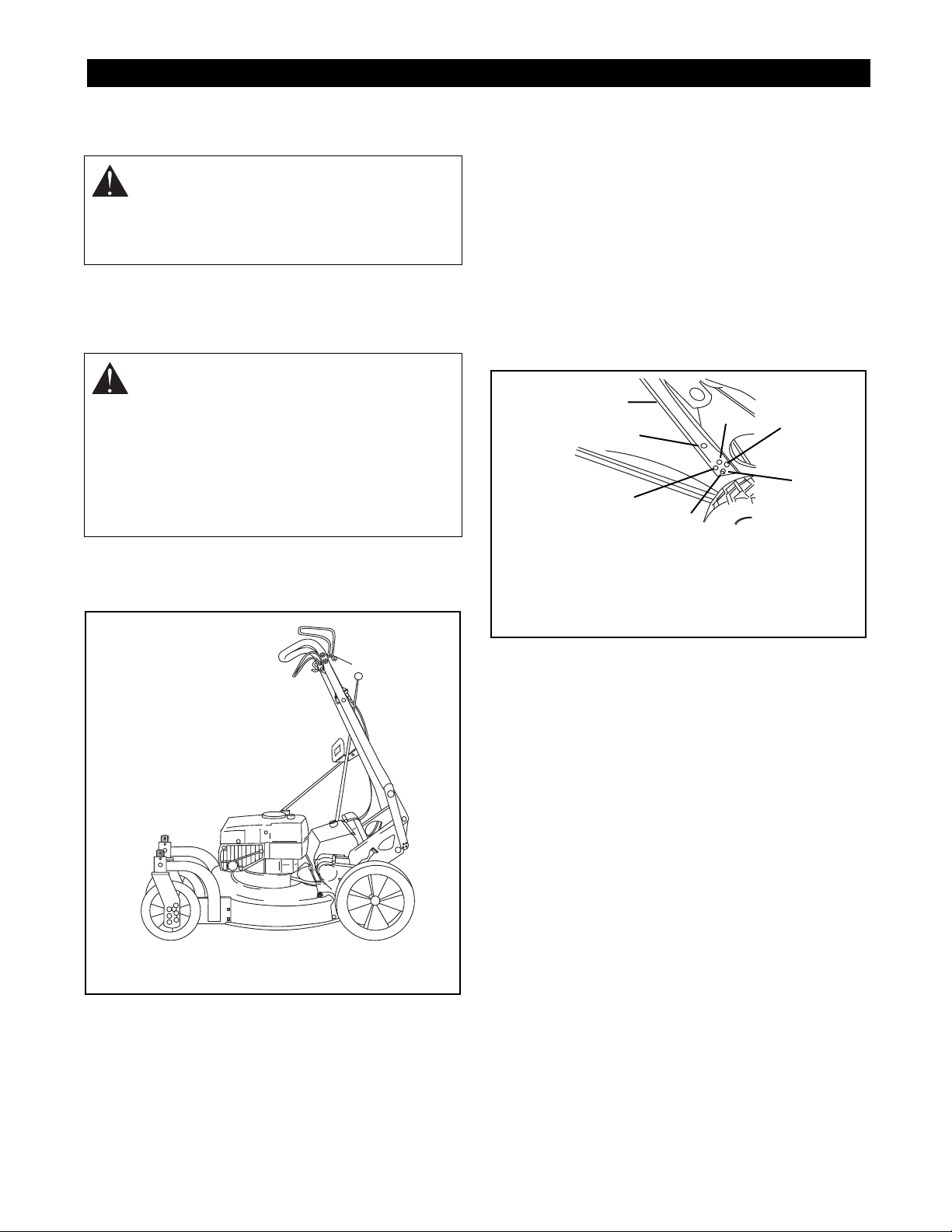
A handlebar service position is provided for tipping the
unit for cleaning and service (Figure 14). See
Adjustments.
IMPORTANT: If engine becomes “flooded” due to
tipping, clean air cleaner (See Maintenance) and
remove spark plug, put one teaspoon of oil in cylinder,
turn engine over a few times and reinstall spark plug.
HANDLEBAR
To adjust handlebar height (Figure 15):
1. Place a hole (1-4) at the bottom of the braces
over the pins.
2. For service position, remove braces from pins,
rotate handlebar forward and place pins into
holes of braces.
Figure 14
IMPORTANT: When tipping to service engine or unit,
use the following service position:
OM0670
Briggs & Stratton Intek Engines: place handlebar
into handlebar service position and tip the machine to
the left, opposite the discharge opening.
18

ENGINE/BLADE CONTROL
Engine Control must stop engine ignition, at 3/4”
to 1-1/4” from handlebar as control is released.
To check (Figure 16):
1. Start engine and slowly release Control until
engine stops firing.
2. Measure distance between handlebar and control
at the point that engine stopped firing.
3. Turn cable nuts at handlebar mount clockwise if
measurement is more than 1-1/4” or
counter-clockwise if measurement is less than
3/4”.
4. Turn nuts against mount to lock in position.
3/4" - 1 1/4 "
2
1
4. Check idler for free rotation of pulley and
movement of pivot.
5. Reinstall drive belt in reverse order. Be sure that
belt seats in pulley grooves with idler positioned
on back (flat) side of belt.
DRIVE WHEEL
See Figure 17.
When the Wheel Drive Control is squeezed toward the
handlebar the extension spring, located at the bottom
end of the traction cable, must start to extend when the
control is between 1-1/2" and 2" (3.8 and 5 cm) away
from the handlebar. To check:
1. Squeeze the Wheel Drive Control toward the
handlebar until the spring starts to open.
2. Measure the distance between the Wheel Drive
Control and handlebar at the handlebar
indentation.
3. To obtain the proper adjustment, turn the cable
nuts. Turn clockwise if the measurement is more
than 2"; counterclockwise if the measurement is
less than 1-1/2". Tighten the nuts against the
bracket to lock in position. If there is not enough
thread length for adjustment, the opposite end of
the cable can be adjusted.
4
3
1. Engine Control
2. Handlebar
3. Cable Nuts
4. Mount
Figure 16
DRIVE BELT (Self propelled units)
To remove drive belt:
1. Position right hand rear wheel Height Adjustment
lever in first notch and left hand rear wheel Height
Adjustment lever in third notch. This provides
clearance between friction wheel and drive disk.
2. Remove belt from idler, drive disk and engine
pulley.
3. Pull belt through opening under mower pan and
over blade.
OM0280
1-1/2" to 2"
2
3
1. Traction Cable
2. Handlebar Indentation
Figure 17
4
1
OM0290
3. Cable Nuts
4. Wheel Drive Control
19

Speed Control Bell Crank
The speed control bell crank holds the speed selector
rod in position after a speed has been set. The spring
washers may become loose with normal wear. If the
speed selector rod does not stay firmly in position,
adjust the speed control bell crank. See Figure 18.
To adjust:
1. Remove cover, fully compress the helical spring
lockwashers with lock nut and then back lock nut
off, one half turn.
2. If the speed selector rod is still too loose, tighten
lock nut by small increments until it holds its
position. Tightening the lock nut too much will not
allow the speed selector rod to move at all.
3. Align notch in left hand side of cover with bolt and
secure with knob.
2
4
5
1. Lock Nut
2. Helical Spring
Lockwashers
3. Speed Control Bell
Crank
1
3
6
OM0300
4. Speed Selector Rod
5. Hair Pin
6. Swivel
Figure 18
STORAGE
WARNING: FLAMMABLE FUEL and its
EXPLOSIVE VAPORS can cause death or
serious injury. DO NOT store unit with fuel in
the fuel tank inside a building where any
ignition sources are present. Drain fuel
outdoors away from any ignition source. Allow
engine to cool before storing in any enclosure.
Only use approved fuel containers.
IMPORTANT: NEVER spray unit with water or store
unit outdoors. Water can seep into sealed bearings,
which are sealed against dirt and debris only, causing
reduced component life. Store mower in a cool, dry,
protected location.
Cleaning
Clean unit thoroughly. Brush dirt and debris off with a
brush. Apply paint or spray lubricant to exposed metal
joints and surfaces. Do not use abrasives, solvents, or
harsh cleaners.
Inspection
Inspect mower for signs of wear or damage. Order any
parts required and make necessary repairs to avoid
delays when beginning use again.
Keep all nuts, bolts and screws tight and know unit is in
safe working condition. Check all hardware at regular
intervals.
Grass Bag
Remove Grass Bag and clean out all debris before
storage. Grass Bag may be stored in position on
mower. Keep Grass Bag dry during storage.
Engine
When storing unit for extended periods of time, remove
all fuel from tank and carburetor (run dry). Refer to
Engine Manual.
20

TROUBLESHOOTING
PROBLEM PROBABLE CAUSE CORRECTION
Engine will
not start
1. Fuel tank empty or low.
2. Spark plug wire loose or off.
3. Engine/brake control cable
detached, broken, or not adjusted
properly.
Self-propelled
drive does not
engage.
1. Traction drive bail not engaged.
2. Drive belt out of position.
3. Drive belt worn or damaged.
4. Rear wheels in different cutting
height positions.
5. Friction wheel engagement not
adjusted properly or damaged.
6. Idler and idler spring installed
incorrectly.
7. Traction drive cable detached or
broken.
8. Bearings damaged.
9. Debris in gear set.
SPECIFICATIONS
Model Number 907254
Description LM21SW
Length - in (cm) 61.5 (156)
Height - in (cm) 38 (96,5)
Width - in (cm) 23 (58,4)
Actual Weight - lbs (kg) 105 (47,6)
Cutting Width 21 (53,3)
Cutting Height - in. (cm) 6 Positions: 1.00 - 3.25
Engine, 4 cycle Briggs & Stratton Intek OHV
Engine Power Max - HP (kw)
Max Rotation Speed
of Cutting Edge - RPM (min
Governed RPM 3000 +/- 100
Displacement Cu. In. (cc) 11.57 (190)
Cylinder Bore Aluminum
Engine Oil Type SAE 30
Crank Case Capacity - Oz. (Liter) 22 (0,65)
Oil System
Spark Plug Gap - in (mm) 0.030 (0,76)
-1
)
(2,5 - 8,3)
4.37 (3,26)
3100
Splash
1. Check fuel level. Fill tank if necessary.
2. Check connection.
3. Check engine/brake control cable. Adjust,
repair or replace as necessary.
1. Engage traction drive bail.
2. Check drive belt. Adjust as necessary.
3. Replace belt.
4. Adjust rear wheel cutting position so that
cutting height is the same on both sides.
5. Adjust or replace friction wheel.
6. Check idler and spring. Adjust as
necessary.
7. Check drive cable. Adjust, repair or replace
as required.
8. Replace bearings.Contact your Dealer.
9. Remove debris. Contact your Dealer.
SPECIFICATIONS
Fuel Type Unleaded
Fuel Tank Capacity - qt (Liter)
Primer Bulb Standard
Air Cleaner Paper Element
Starting Recoil
Differential Standard
Variable Speeds - MPH (km/hr) 0-4 (0-6,4)
Mower Deck 14 Gauge - Stamped Steel
Adjustable Handlebar Four Position
Front Wheel Dia - in (cm) 7.5 (19,1)
Rear Wheel Dia - in (cm) 10.5 (26,7)
1.6 (1,5)
21
 Loading...