


S1642
Table of contents
 Loading...
C0
Scotts Lawn Tractors
S1642, S1742, and S2046
OPERATOR’S MANU AL
OMGX10784 C0
North American Version
Litho in U.S.A.
INTRODUCTION
Introduction
THANK YOU for purchasing a Scotts product.
Read this manual and your attachment manual thoroughly.
Failure to do so could result in personal injury or equipment
damage.
This manual should be considered a permanent part of
your machine and should remain with the machine when
you sell it.
Product warranty is provided as part of John Deere’s
support program for customers who operate and maintain
their equipment as described in this manual. The product
warranty is explained on the warranty certificate you
received from your dealer.
Measurements in this manual are metric units and their
U.S. customary equivalents. RIGHT-HAND and LEFTHAND sides are determined by facing in the direction the
machine will travel when going forward. When you see a
broken line arrow (------>), it indicates the part it is pointing
to is hidden.
CALIFORNIA Proposition 65 Warning
Warning:
g
The Engine Exhaust from
this product contains chemicals known to the
State of California to cause cancer, birth
defects or other reproductive harm.
Introduction
PRODUCT IDENTIFICATION
Product Identification
Record Identification Numbers
Scott’s Lawn Tractors
S1642, S1742, and S2046
If you need to contact an Authorized Service Center for
information on servicing, always provide the product model
and serial number.
You will need to locate the identification number for the
machine and for the engine. Record the information in the
spaces provided below.
PIN (020001 - )
DATE OF PURCHASE:
_________________________________________
DEALER NAME:
_________________________________________
DEALER PHONE:
_________________________________________
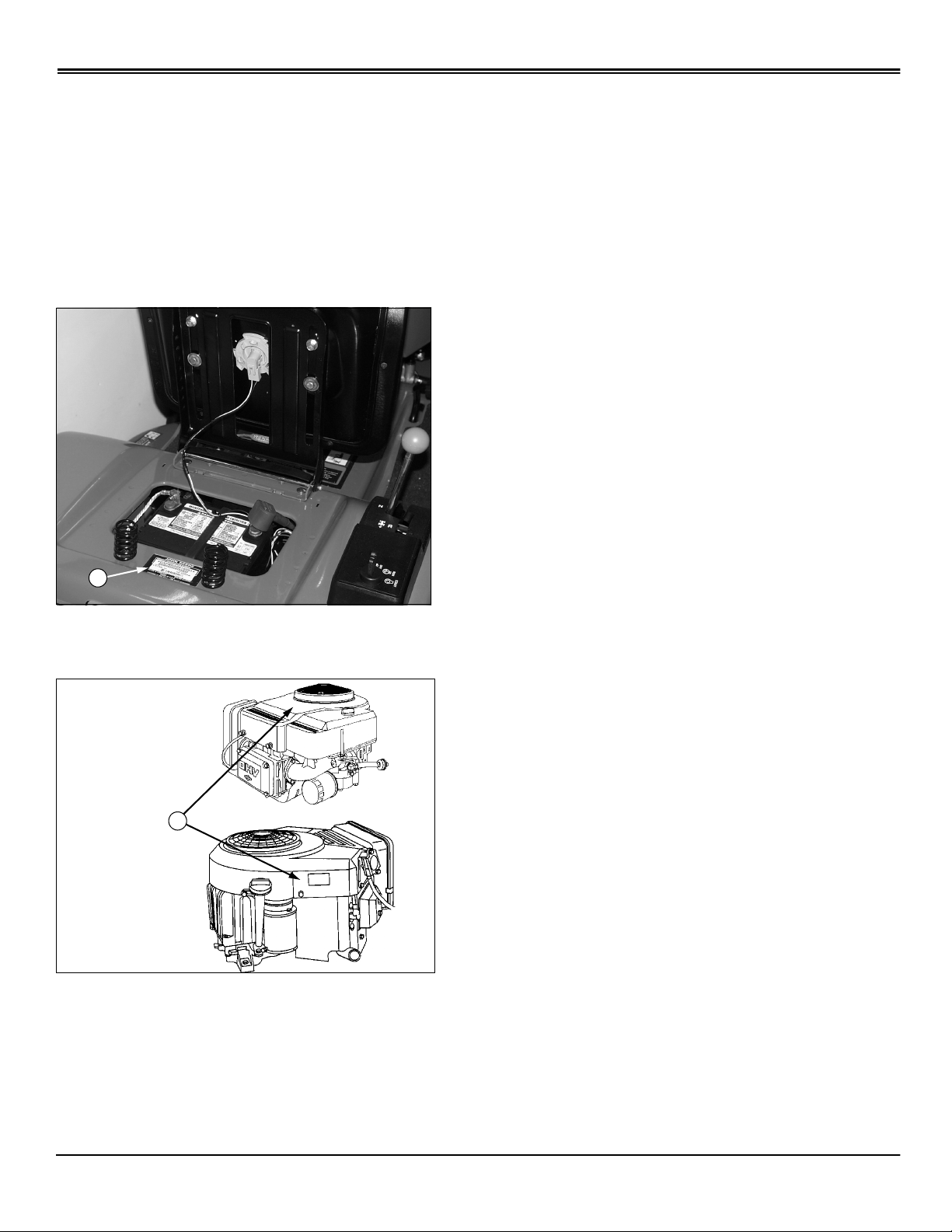
A
PRODUCT IDENTIFICATION NUMBER (A), (under seat):
__ __ __ __ __ __ __ __ __ __ __ __ __ __ __ __ __
Model S1742 and S2046
B
Model S1642
ENGINE SERIAL NUMBER (B), (on fan shroud):
__ __ __ __ __ __ __ __ __ __ __ __ __ __ __ __ __
Product Identification
Assembly
B
C
A
Identify Parts
ASSEMBLY
A Operator’s Manual
B Safety Video
C Bag of Hardware
DKey
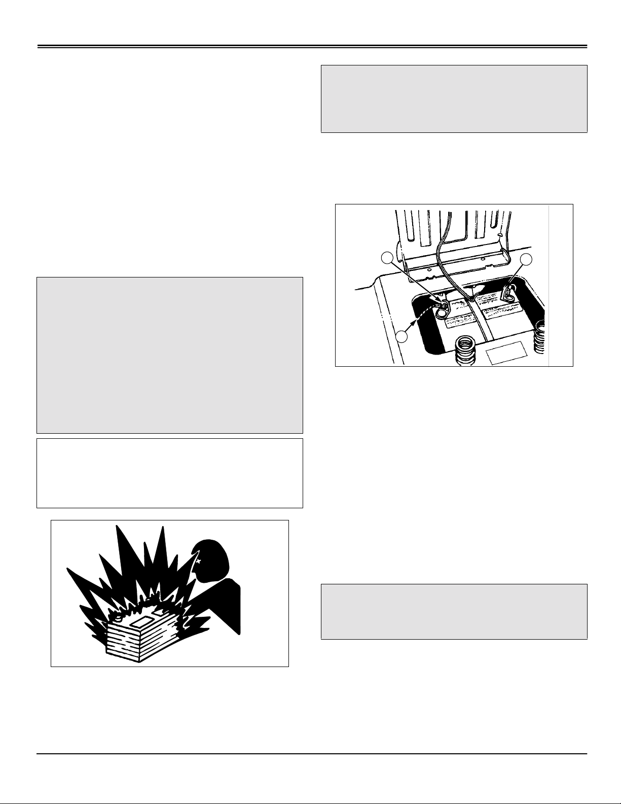
Bag of Hardware:
• 2 - M8x16 Bolts - Battery
• 2 - M8x16 Nuts - Battery
Connect and Check Battery
c
CAUTION: Avoid injury! Prevent Battery
Explosions:
- Keep sparks, lighted matches, and open flame
away from the top of battery. Battery gas can
explode.
- Never check battery char ge by placing a metal
object across the posts. Use a volt-meter or
hydrometer.
- Do not charge a frozen battery; it may
explode. Warm battery to 16° C (60° F)
IMPORTANT: Avoid damage! This battery comes
fully charged. If the mower is not used by the
Service Expiration Date indicated on the battery,
charge the battery. (See Charging the Battery in the
Service - Electrical section.)
c
CAUTION: Avoid injury! DO NOT attempt to
open, add fluid or service battery. Any attempt
to do so will void warranty and lead to possible
injury.
NOTE: Do not remove the BLACK negative (–)
protective cap at this time.
1. Remove and discard the RED positive (+) protectiv e cap
from the positive (+) battery terminal.
2. Connect RED positive (+) cable (A) to battery with 6mm
hex head bolt and 6 mm flange nut. Tighten securely. Apply
petroleum jelly or silicone spray to terminal to prevent
corrosion. Install the red terminal cover.
3. Remove and discard the BLA CK (–) protectiv e cap from
the negative battery terminal.
4. Connect silver braided grounding cable (B) to the
negative (–) terminal (C) with remaining 6 mm hex head
bolt and 6 mm flange nut and tighten securely. Apply
petroleum jelly or silicone spray to terminal to prevent
corrosion.
42-Inch Mowers Only
c
CAUTION: Avoid injury! Never operate the
mower without the discharge chute guard in
place.
• If tractor/mower deck is being set-up f or mulching, install
mulch cover kit. (See Using Mower Deck Mulch Ready in
the Operating Mower section.)
Assembly - 0
• If tractor/mower deck is being set-up for side discharger
or 2-bag bagger DO NOT install mulch cover kit. (See
Using Mower Deck Side Discharge OR Using Mower Deck
with Optional Equipment in the Operating Mower section.)
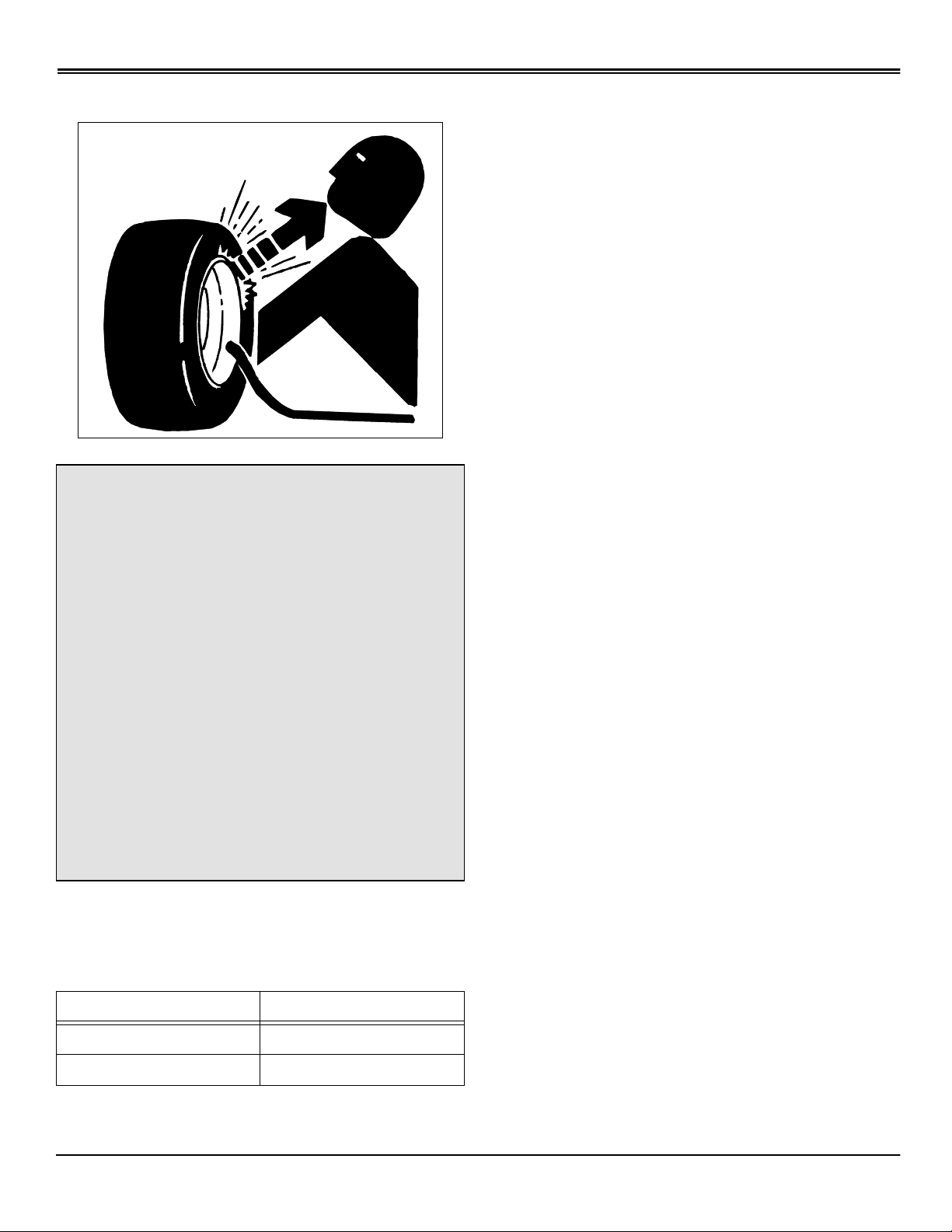
Checking Tire Pressure
c
CAUTION: Avoid injury! Explosive separation
of a tire and rim parts can cause serious injury
or death:
ASSEMBLY
- Do not attempt to mount a tire without the
proper equipment and experience to perform
the job.
- Always maintain the correct tire pressure. Do
not inflate the tires above the recommended
pressure. Never weld or heat a wheel and tire
assembly. The heat can cause an increase in
air pressure resulting in a tire explosion.
Welding can structurally weaken or def orm the
wheel.
- When inflating tires, use a clip-on chuck and
extension hose long enough to allow you to
stand to one side and NOT in front of or over
the tire assembly.
- Check tires for low pressure, cuts, bubbles,
damaged rims or missing lug bolts and nuts.
1. Check tires for damage.
2. Check tire pressure with an accurate gauge.
3. Add or remove air, if necessary:
Tire Size Pressure-kPa (psi)
Front: 15-Inch 97 kPa (14 psi)
Rear: 20-Inch 69 kPa (10 psi)
Assembly - 1
SAFETY SIGNS
M96445
Safety Signs
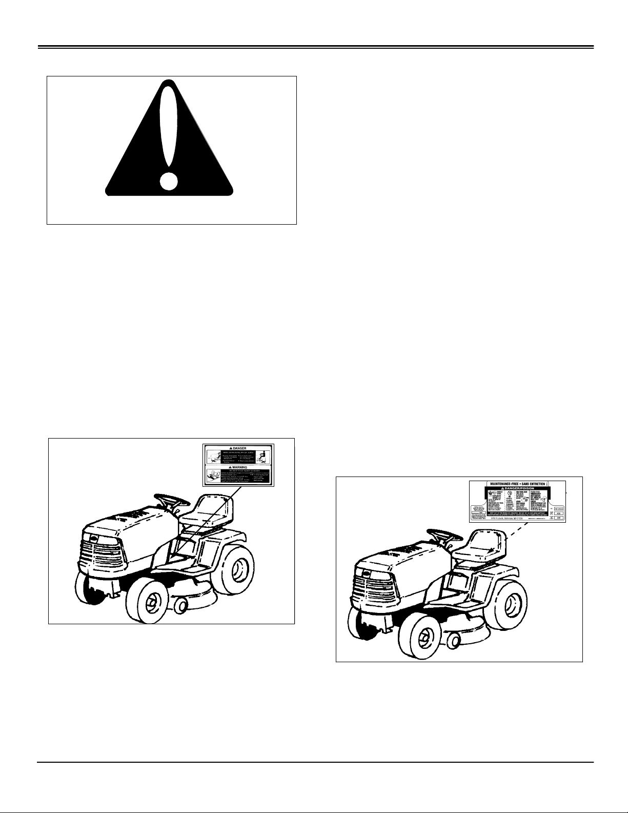
Safety-Alert Symbol
Read and recognize safety information. Be alert to the
potential for personal injury when you see this safety-alert
symbol.
On your machine safety labels, the words DANGER,
WARNING, and CAUTION are used with this safety-alert
symbol. DANGER identifies the most serious hazards.
In this manual, the word CAUTION and this symbol call
attention to safety messages.
• Avoid sudden turns
• If machine stops going uphill, stop blade and back down
slowly
• Keep safety devices (guards, shields, and switches) in
place and working
• Read operator’s manual
• When leaving machine:
–Stop engine
–Set park brake
–Remove key
DANGER/POISON
SHIELD EYES.
EXPLOSIVE GASES CAN CAUSE BLINDNESS OR
INJURY.
NO
• SPARKS
• FLAMES
• SMOKING
Machine Safety Labels
DANGER
AVOID SERIOUS INJURY OR DEATH
M96445
• Do not mow when children or others are around
• Do not mow in reverse
SULFURIC ACID CAN CA USE BLINDNESS OR SEVERE
BURNS
FLUSH EYES IMMEDIATELY WITH WATER.
GET MEDICAL HELP FAST.
MAINTENANCE-FREE
KEEP OUT OF THE REACH OF CHILDREN. DO NO T TIP.
DO NOT OPEN BATTERY!
• Look down and behind before and while backing
• Never carry children even with blades off
WARNING
AVOID SERIOUS INJURY OR DEATH
• Drive up and down slopes, not across
Picture Note: Located on Battery under seat
DANGER
ROTATING BLADE
DO NOT PUT HANDS OR FEET UNDER OR INTO
Safety Signs - 2
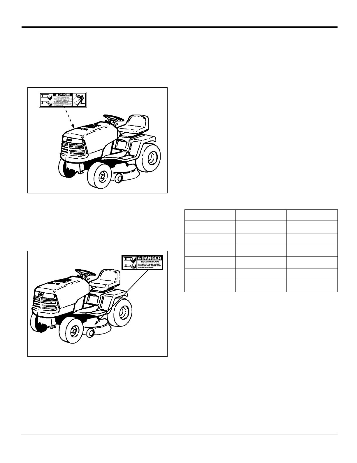
SAFETY SIGNS
MOWER WHEN ENGINE IS RUNNING
THROWN OBJECTS
BEFORE MOWING, CLEAR AREA OF OBJECTS THAT
MAY BE THROWN BY BLADE
DO NOT OPERATE MOWER WITHOUT DISCHARGE
CHUTE OR ENTIRE GRASS CATCHER IN PLACE
M96445
Picture Note: Located on Right-Hand side of deck
authorized service centers. Contact your John Deere
Commercial and Consumer Equipment Retailer
concerning emission controls and component
questions.
The presence of an emissions label signifies that the
engine has been certified with the United States
Environmental Protection Agency (EPA) and/or California
Air Resources Board (CARB).
The emissions warranty applies only to those engines
marketed by John Deere that have been certified by the
EPA and/or CARB; and used in the United States and
Canada in off-road mobile equipment.
Emission Compliance Period
If your engine has the emission compliance category listed
on the emission control system certification or air index
label, this indicates the number of operating hours for which
the engine has been certified to meet EPA and/or CARB
emission requirements. The following table provides the
engine compliance period in hours associated with the
category found on the certification label.
DANGER
ROTATING BLADE
DO NOT PUT HANDS OR FEET UNDER OR INTO
MOWER WHEN ENGINE IS RUNNING
M96445
Picture Note: Located on Left-Hand side of deck
Agency Category Hours
EPA C 250
EPA B 500
EPA A 1000
CARB Moderate 125
CARB Intermediate 250
CARB Extended 500
Certification
Your mower has been certified by an independent
laboratory for compliance with American National Standard
B-71.1, “Safety Specifications” for Power Lawn Mowers,
Lawn and Garden Tractors, and Lawn Tractors.
Emission Control System Certification Label
NOTE: Tampering with emission controls and
components by unauthorized personnel may result in
severe fines or penalties. Emission controls and
components can only be adjusted by EPA and/or CARB
Safety Signs - 3
CONTROLS
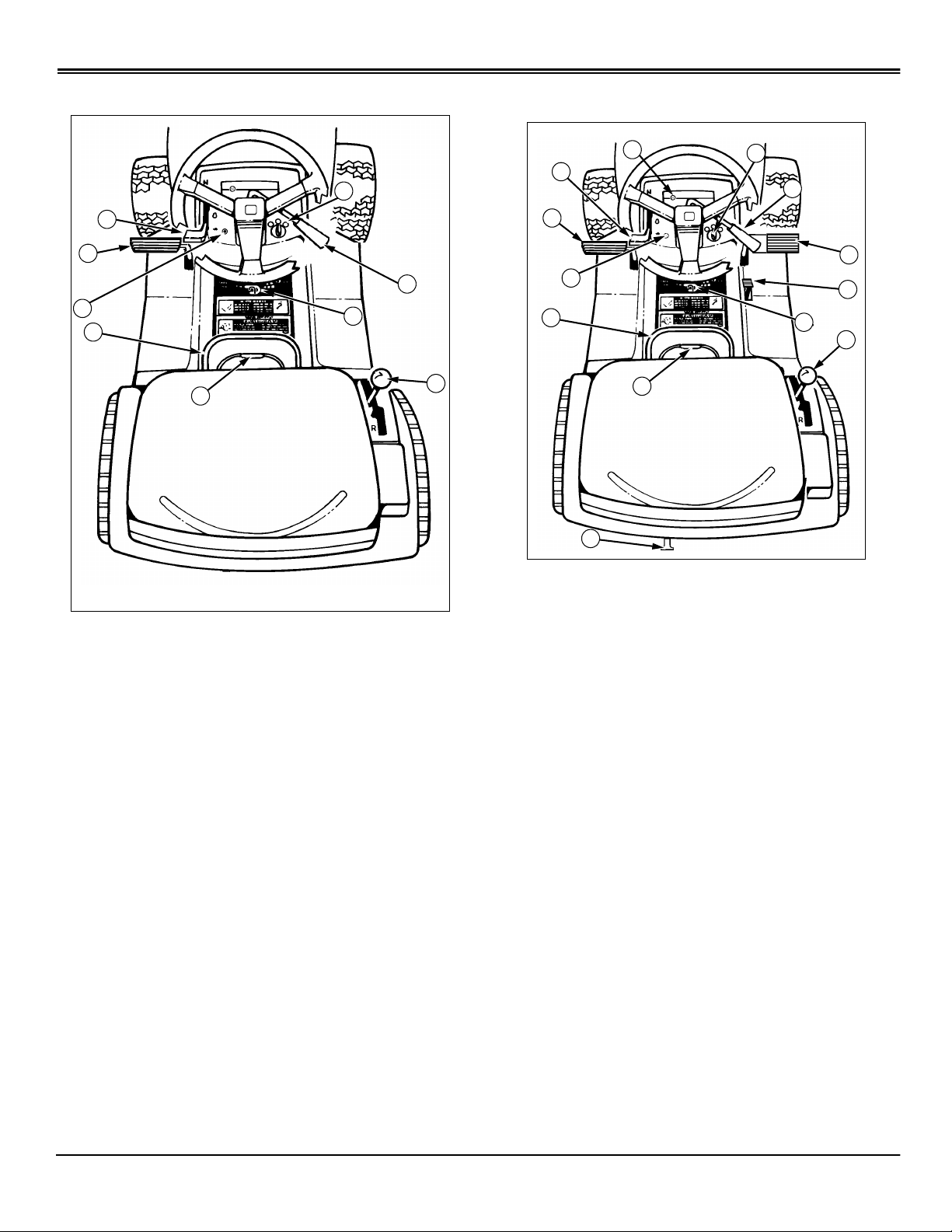
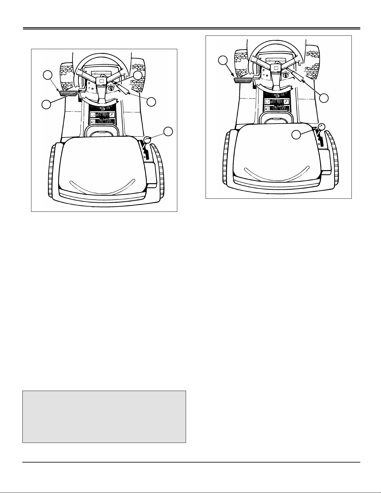
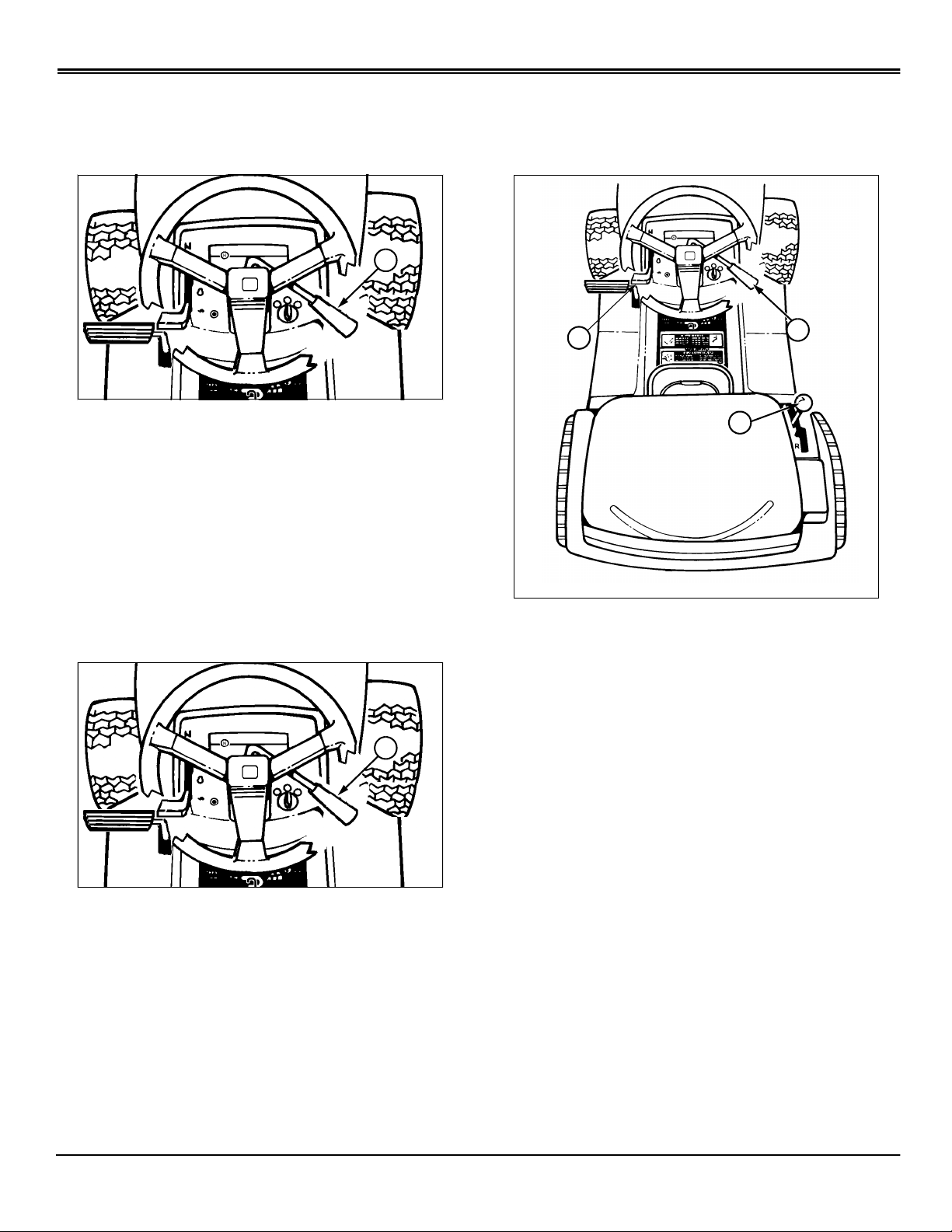
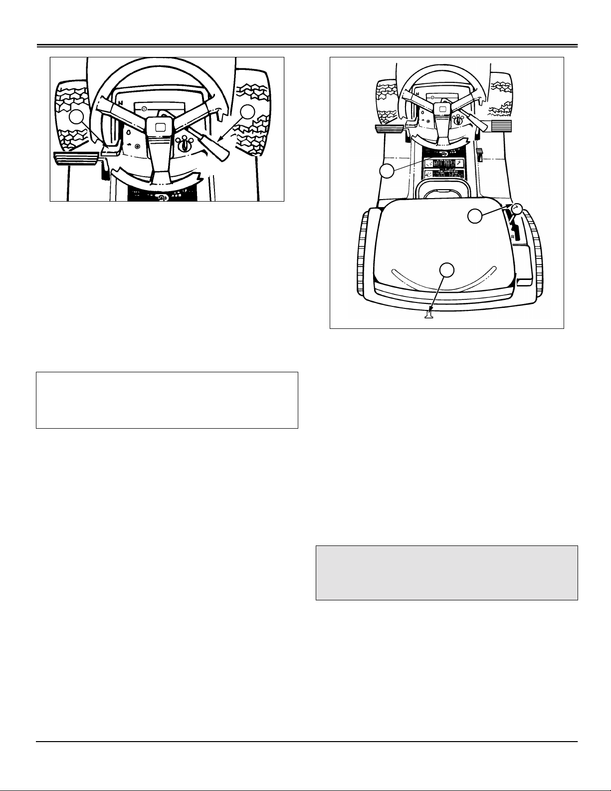
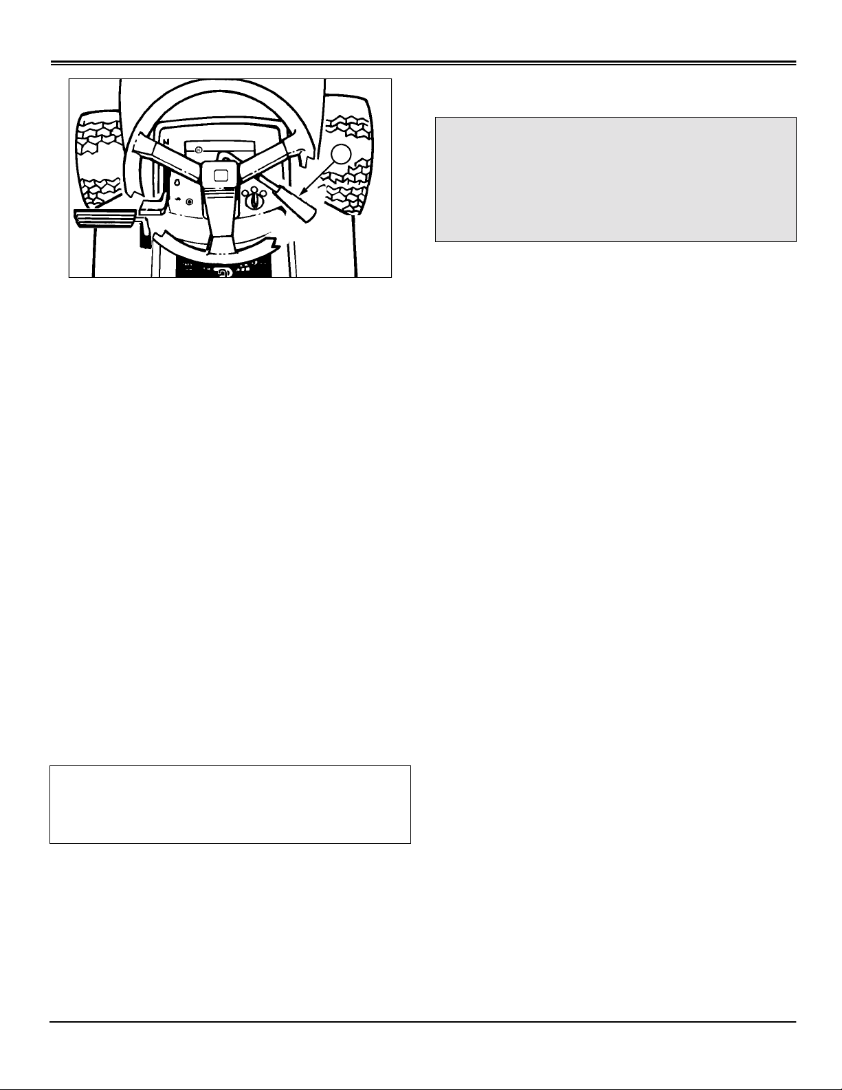
Controls
Tractor Controls - Gear
A
B
C
D
E
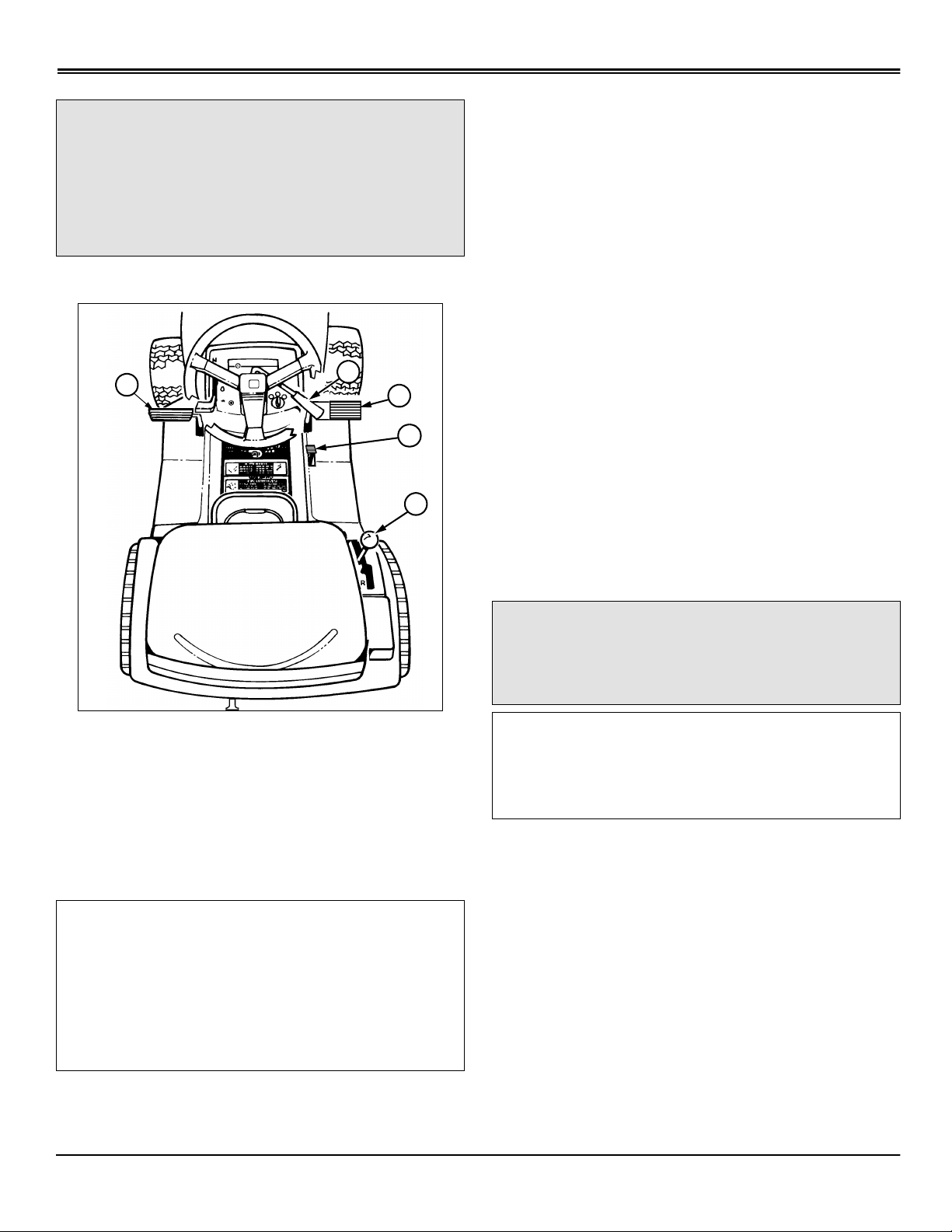
Tractor Controls - Automatic
A
B
I
C
H
G
F
D
E
F
M
L
K
J
I
H
A - Throttle/Choke Control
B - Foot Pedal - Brake/Clutch
C - Reverse Implement Option Switch
D - Attachment Lift Lever
E - Locking Lever
F - Transmission Shift Lever
G - Park Brake
H - PTO Drive Lever
I - Ignition Switch
G
A - Choke Knob (S2046)
B - Throttle/Choke Control (S1642 and S1742)
Throttle Control (S2046)
C - Foot Pedal - Brake/Clutch/Return to Neutral
D - Reverse Implement Option Switch
E - Attachment Lift Lever
F - Locking Lever
G - Free Wheeling Knob
H - Transmission Shift Lever (Hand Control Units
Only) Cruise Control Lever (Foot Control Units
Only)
I - Park Brake
J - Foot Pedal, Reverse (Foot Control Units Only)
K - Foot Pedal, Forward (Foot Control Units Only)
L - PTO Drive Lever
M - Ignition Switch
Controls - 4
OPERATING MACHINE
Operating Machine
Operate Safely
• In addition to reading your Operator’s Man ual, vie w y our
Mowing Safety Video.
• Check brake action before you operate. Adjust or
service brakes as necessary.
• Inspect machine before you operate. Be sure hardware
is tight. Repair or replace damaged, badly worn, or missing
parts. Be sure guards and shields are in good condition
and fastened in place. Make any necessary adjustments
before you operate.
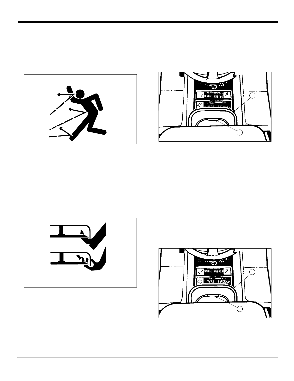
• Clear work area of objects that might be thrown. Keep
people and pets out of the work area. Stop machine if
anyone enters the area.
• If you hit an object, stop the machine and inspect it.
Make repairs before you operate. Keep machine and
attachments properly maintained and in good working
order.
• DO NOT leave machine unattended when it is running.
• Only operate during daylight or with good artificial light.
• Be careful of traffic when operating near or crossing
roadways.
• Do not wear radio or music headphones while operating
the machine. Safe operation requires your full attention.
• Older adults are involved in a large percentage of riding
mower accidents involving injury. These operators should
evaluate their ability to operate a mower safely enough to
protect the operator and others from serious injury.
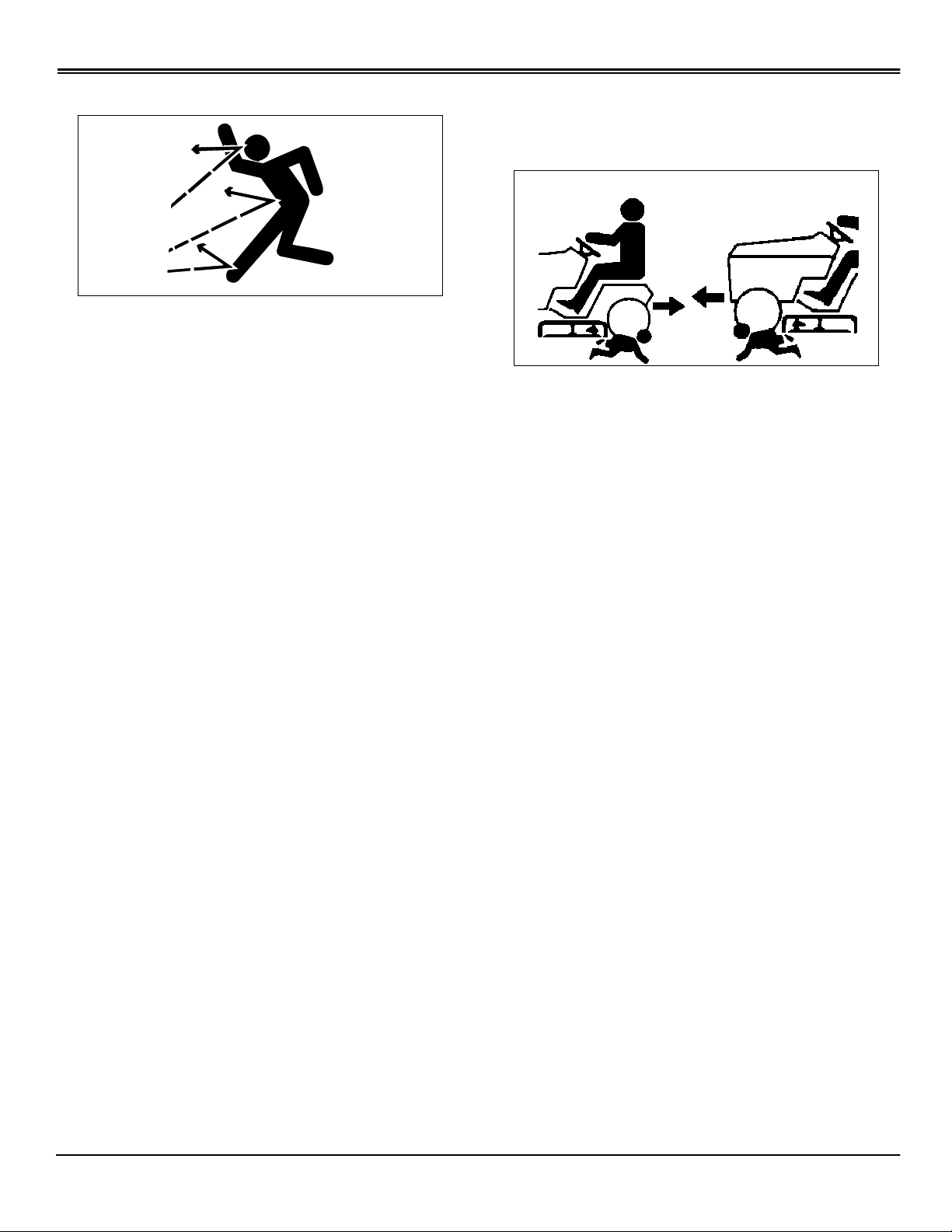
Rotating Blades are Dangerous - Protect Children and Prevent Accidents
PROTECT CHILDREN:
• Never assume that children will remain where you last
saw them. Children are attracted to mowing activity, stay
alert to the presence of children.
• Keep children in the house when you are operating the
machine.
• Turn machine off if a child enters the mowing area.
• Use extra care when y ou come to b lind corners, shrubs,
trees, or other objects that may block your vision.
• DO NOT let children or an untrained person operate the
machine.
• DO NOT carry or let children ride on machine or any
attachment even with the blades off. DO NOT tow children
in a cart or trailer.
HELP PREVENT SERIOUS OR FATAL ACCIDENTS:
• Be alert at all times, drive forward carefully. People
especially children can move quickly into the mowing area
before you know it.
• Back carefully. Disengage mower blades and look
behind the machine carefully, especially for children, before
you back up.
• DO NOT mow in reverse unless it is absolutely
necessary.
• Disengage mower blades when you are not mowing.
Park Safely
• Stop machine on a level surface, not on a slope.
• Disengage mower blades.
• Lower attachments to the ground.
• Engage park brake.
• STOP engine.
• Remove key.
• Before you lea ve the operator’s seat, wait for engine and
all moving parts to STOP.
Operating Machine - 5
• DO NOT operate machine if y ou are under the influence
of drugs or alcohol.
OPERATING MACHINE
Avoid Tipping
• DO NOT drive where machine could slip or tip.
• Stay alert for holes and other hidden hazards in the
terrain.
• Keep away from drop-offs.
• Slow down before you make a sharp turn or operate on
a slope.
• When pulling loads or using heavy equipment, use only
approved hitches, limit loads to those you can safely
control, and use counterweights or wheel weights when
required per this manual or your attachment manual.
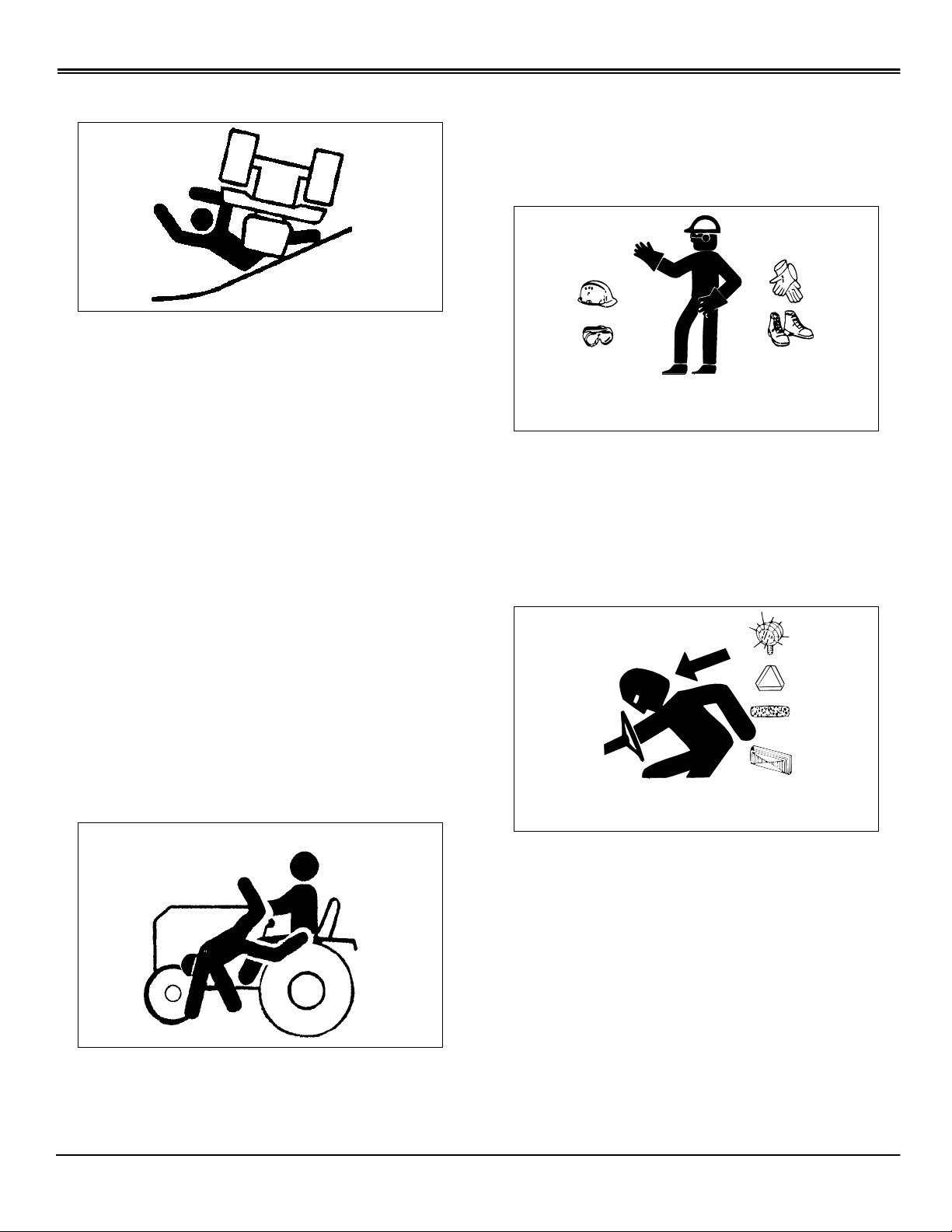
• Riders obstruct the operator’s view resulting in the
machine being operated in an unsafe manner.
Wear Appropriate Clothing
• Wear close fitting clothing and safety equipment
appropriate for the job.
• Loud noise can cause impairment or loss of hearing,
wear a suitable protective device such as earplugs.
• Drive up and down a hill—not across. Be careful when
you change direction on a slope.
• DO NOT stop when going up hill or do wn hill. If machine
stops going up hill, DISENGAGE mower blades and back
down slowly.
• DO NOT mow wet grass. Reduced traction could cause
sliding.
• DO NOT try to stabilize the machine by putting y our foot
on the ground.
Keep Riders Off
Transport Safely
• Use safety lights and devices. Slow moving machines
when driven on public roads are hard to see, especially at
night. Avoid personal injury or death resulting from a
collision with a vehicle.
• Whenever driving on public roads, use flashing warning
lights and turn signals according to local regulations. Extra
flashing warning lights may need to be installed.
• Only allow the operator on the machine. Keep riders off.
• Riders on the machine or attachment may be struck by
foreign objects or thrown off the machine causing serious
injury.
Operating Machine - 6
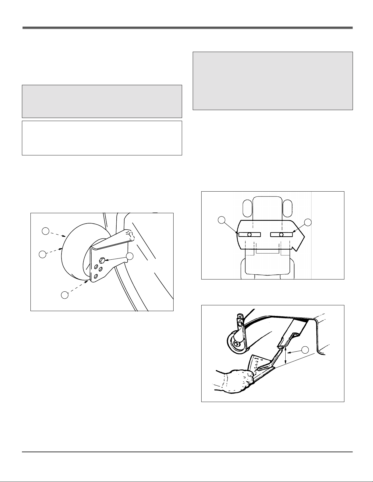
Adjusting Seat
1. Pivot seat forward on its mounting bracket.
OPERATING MACHINE
A
B
A
M96454
Picture Note: Model with capscrew adjuster used
for illustration.
2. Loosen two cap screws (A) two turns.
3. Slide forward or rearward on mounting bracket to
desired position.
4. Tighten cap screws or knobs.
5. Lower seat.
Using Slide Adjuster (S2046)
1. Pivot seat forward on its mounting bracket.
B
2. Pull pin (B) and rotate pin to the locked position.
3. Slide seat forward or rearward to desired position.
4. Release pin, make sure pin engages in hole in frame.
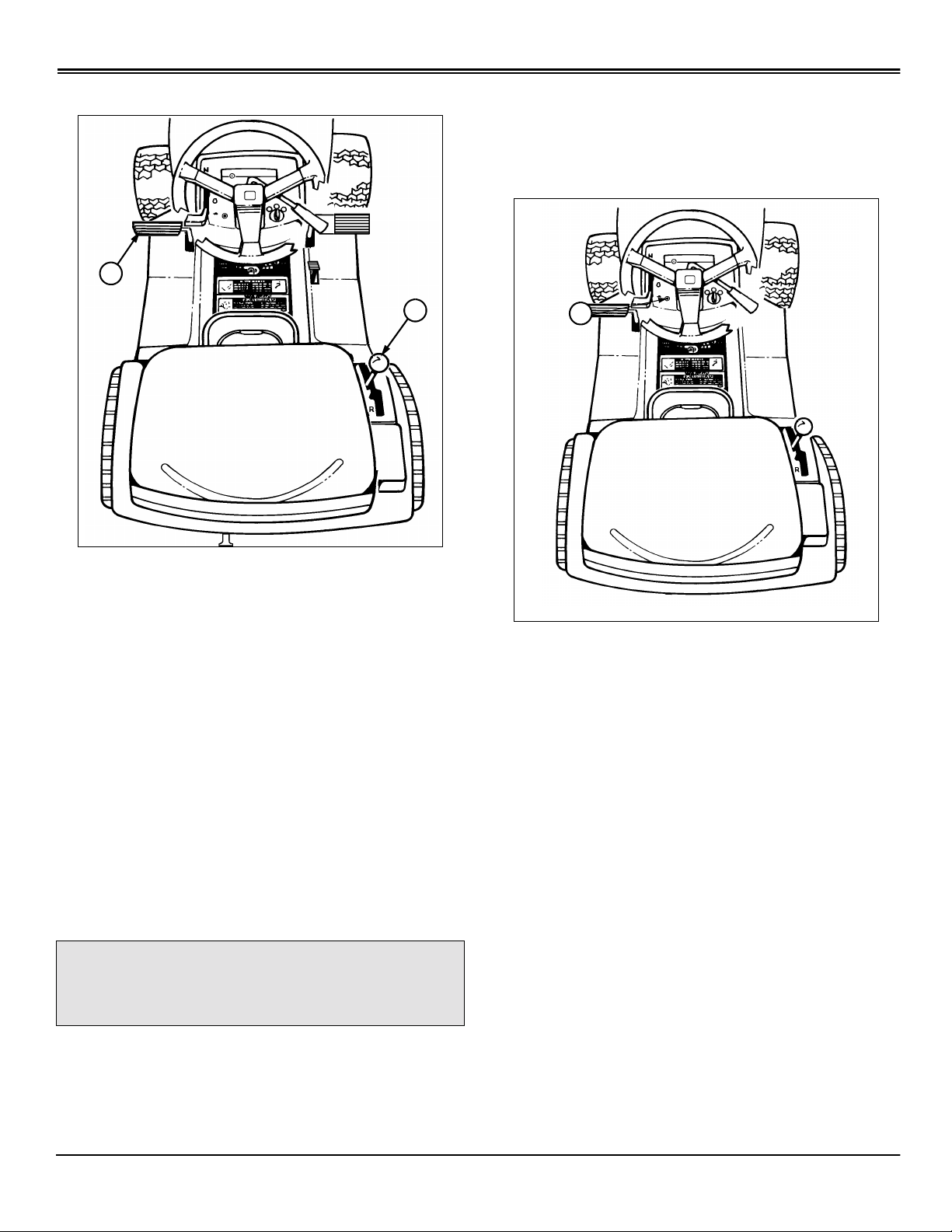
Using the Park Brake
c
CAUTION: Avoid injury! Always LOCK park
brake before getting off tractor or leaving
tractor unattended.
1. Push and hold foot pedal (A) all the way down.
2. Move park brake le v er (B) f orward, then to the left to loc k
position.
3. Remove foot from pedal. Pedal should not return to the
up position.
UNLOCKING PARK BRAKE
1. Push and hold foot pedal (A) all the way down.
2. Move park brake lever (B) to the right, then to the rear.
3. Remove foot from pedal. Pedal should return to the up
position.
Starting Engine
c
CAUTION: Avoid injury! Start engine ONLY
outdoors or in a well ventilated place. Exhaust
fumes are dangerous.
IMPORTANT: Avoid damage! Do not operate starter
more than 20 seconds at a time, or you may damage
it. If engine does not start: Wait two minutes before
you try again. See Troubleshooting section.
LOCKING PARK BRAKE:
NOTE: Engine will not start unless: PTO lever is
DISENGAGED, park brake is LOCKED or brake/clutch
pedal is pushed down. On GEAR model: The
transmission shift lever should be in N (NEUTRAL)
position.
Operating Machine - 7
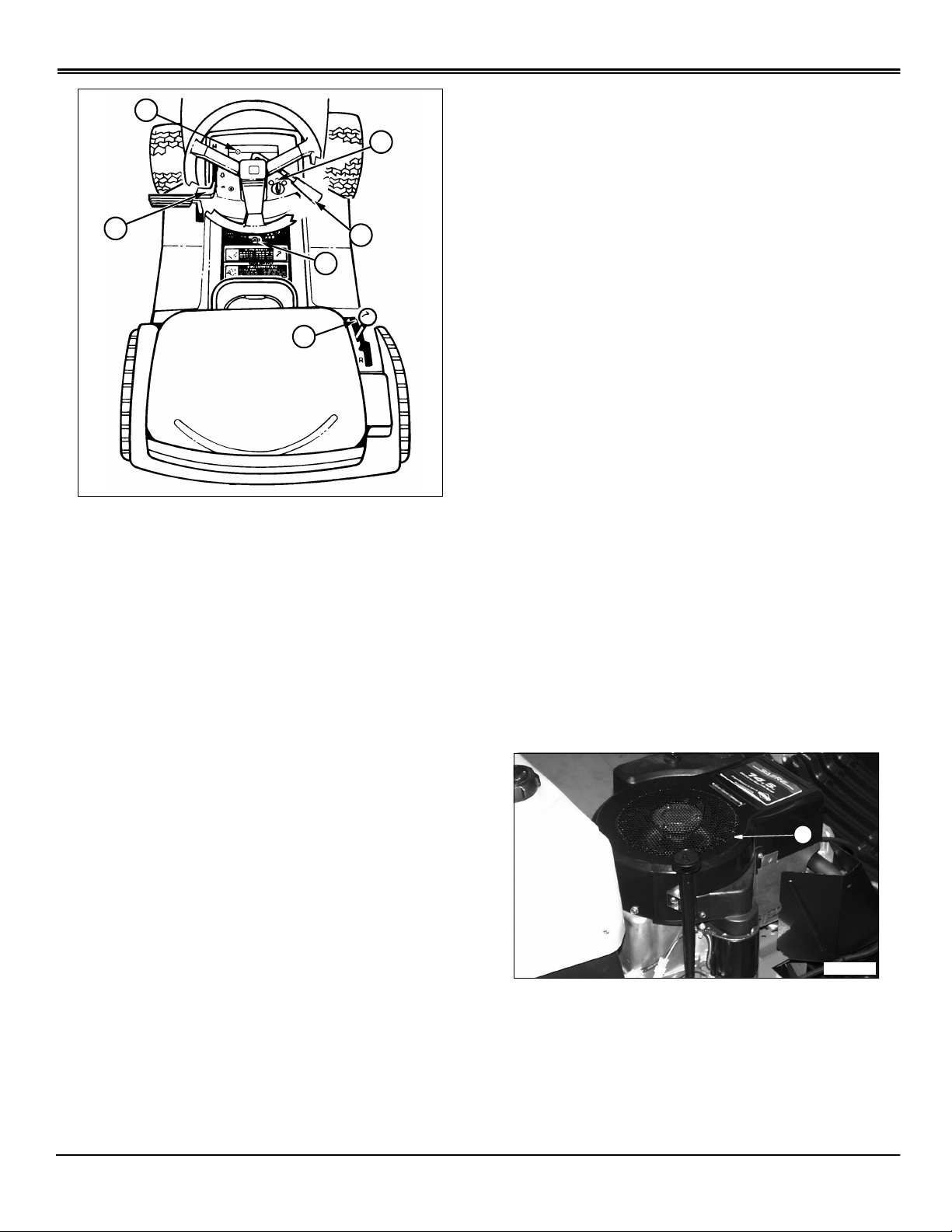
OPERATING MACHINE
M96455
A
Using Throttle Control
E
F
Always operate the engine at FULL (r)THROTTLE.
Operating the engine at less that full throttle reduces the
battery charging rate and reduces fan cooling efficiency of
the engine.
D
A
1.
Gear units
(NEUTRAL) position.
Automatic units
lever to N (NEUTRAL) position. If equipped with foot pedal
controls, do not depress either pedal.
2. Lock the park brake (B).
3. Pull PTO lever (C) all the way back to the rearward
(OFF) position.
4. To start the engine:
• S1642 and S1742 - Place the throttle lever (D) in the
CHOKE (
smoothly, lower the throttle lever in small steps, allowing
the engine to accept changes in speed and load, until
the throttle lever is in the FAST (
- Move transmission shift lever (A) to N
- If equipped with shift lever, move shift
) position. As the engine begins to run
k
r
C
B
) position.
Full throttle offers the best bagging and mower
performance.
Cold Weather Starting Tips
Always use fresh winter grade fuel.
Do not crank engine for more than 30 seconds in an y single
attempt.
During first minute of operation engine may be operated in
partial choke to allow smoother running. As engine warms
slowly reduce engine speed to the full throttle detent
position.
On Automatic Transmission
Allow engine to run for a f ew minutes bef ore using tractor to
allow automatic transmission oil to warm. Sluggish
transmission response in cold weather indicates that oil has
not warmed to allow optimum performance.
Warming and Idling Engine
WARMING ENGINE:
• Run Engine at half speed for 2–3 minutes.
IDLING ENGINE:
• S2046 - Place the throttle lever (D) the FAST (
position and pull out choke knob (E). As the engine
begins to run smoothly , push the choke knob in until fully
seated.
5. Turn ignition key (F) to start position to crank the engine.
Crank engine until it starts, but no longer than 5 seconds.
6. If engine starts, release key to run position. If engine
does not start, release key to run position and wait 10
seconds before cranking the engine again.
7. Let engine run for a couple of minutes to warm-up
before operating tractor.
)
r
Operating Machine - 8
• Engine is air-cooled and needs a large volume of air to
keep cool. Keep air intake screen (A) on top of engine
clean.
• Avoid unnecessary engine idling.
Stopping Engine
B
C
A
OPERATING MACHINE
A
D
1. Push down on foot pedal (A).
2.
Gear units
(NEUTRAL) position.
Automatic units
lever to N (NEUTRAL) position. If equipped with foot pedal
controls, release either pedal and unit will automatically
return to neutral. If cruise control is engaged, move lever to
OFF position.
3. Pull PTO lever (C) all the way back to the rearward
(OFF) position.
4. Move throttle lever (D) to SLOW (t) position. Let engine
run at low throttle a few seconds.
5. Turn key (E) to OFF position.
6. Remove key.
7. LOCK the park brake.
- Move transmission shift lever (B) to N
- If equipped with shift lever, move shift
E
C
B
1. Push foot pedal (A) all the way forward to the BRAKE
position.
2. Move shift lever (B) to the right and forward to desired
FORWARD position.
3. Slowly release foot pedal to engage machine drive.
TO TRAVEL IN REVERSE:
NOTE: The engine and mower will stop as the shift
lever is moved to the R (REVERSE) position with
mower engaged.
1. Push foot pedal (A) all the way down to STOP tractor.
2. Pull PTO lever (C) all the way back to the rearward
(OFF) position.
3. Look behind the vehicle to be sure there are no
bystanders nearby.
4. Move shift lever (B) to the right and rearward to the R
(REVERSE) position.
5. Release foot pedal slowly.
Using Travel Controls - Gear
c
CAUTION: Avoid injury!
• Before moving forwar d or rearward, make sure
area is clear of bystanders, especially c hildren.
• Disengage mower or attachment before
backing up.
TO TRAVEL FORWARD:
FOR EMERGENCY STOPPING:
1. Push foot pedal (A) fully to stop machine.
Using Travel Controls - Automatic
Operating Machine - 9
OPERATING MACHINE
c
CAUTION: Avoid injury!
• Before moving forward or rearward, make
sure area is clear of bystanders, especially
children.
• Disengage mower or attachment before
backing up.
To Travel Forward:
E
1.
Units with Shift Lever (A)
lever (A) re ward into the R (REVERSE) position. The speed
of the tractor is determined by how far forward the shift
lever is moved.
Units with Foot Controls (C)
The speed of the tractor is determined by how f ar do wn the
pedal is pressed.
2. Pull PTO lever (C) all the way back to the rearward
(OFF) position.
3. Look behind the vehicle to be sure there are no
bystanders nearby.
FOR EMERGENCY STOPPING:
1.
Units with Shift Lever (A)
D
B
C
A
(E). Transmission shift lever (A) will automatically return to
NEUTRAL position and brakes will be applied.
Units with Foot Controls (C)
move lever to OFF position. Release either pedal (B or C)
and unit will automatically return to neutral and STOP. Push
down on brake/clutch pedal (E). Brakes will be applied to
assist in stopping.
- Move transmission shift
- Depress reverse pedal (C).
- Push down on foot pedal
- If cruise control is engaged,
1.
Units with Shift Lever (A)
lever (A) to the right and forw ard. The speed of the tractor is
determined by how far forward the shift lever is moved.
Units with Foot Controls (B)
The speed of the tractor is determined by how f ar do wn the
pedal is pressed.
TO TRAVEL IN REVERSE:
IMPORTANT: Avoid damage! To prevent
transmission damage, stop tractor movement before
changing direction of travel.
When cruise control is not in use, hand lever should
be returned manually, all the way rearward to OFF
position. Otherwise, hand lever will restrict travel of
reverse pedal linkage and reverse speed of tractor
will be too slow.
- Move transmission shift
- Depress forward pedal (B).
Using Cruise Control
c
CAUTION: Avoid injury! DO NOT use cruise
control when going down hills. Tractor speed
will increase. Operate tractor in a large, open
area to learn how the cruise control works
IMPORTANT: Avoid damage! When cruise control is
not in use, hand lever should be returned manually,
all the way rearward to OFF position. Otherwise,
hand lever will restrict travel of rever se pedal linkage
and reverse speed of tractor will be too slow.
Use cruise control when you want to maintain travel speed
without having to hold the forward travel pedal down.
Cruise control operates only for forward travel.
NOTE: The engine and mower will stop as the drive
lever is moved to the R (REVERSE) position with
mower engaged.
Operating Machine - 10
OPERATING MACHINE
A
ENGAGE CRUISE CONTROL:
B
1. Stop the machine FORWARD travel with mower
engaged. On foot control models, be sure cruise control
lever is all the way rearward in the OFF position.
2. Look behind the vehicle to be sure there are no
bystanders.
A
1. Start with the cruise control lever (A) in the OFF
position.
” position the
2. Move cruise control lever f orward, at the”
tractor will begin to move forward.
3. Continue to move cruise control lev er f orward toward the
“
” position and the tractor will increase in speed.
r
4. Move cruise control lever to the desired speed and
release lever.
DISENGAGE CRUISE CONTROL:
NOTE: Depressing brake/clutch pedal (B) will return
cruise control lever to the OFF position.
1. Move the cruise control lever to the OFF position.
t
Using Reverse Implement Option
c
CAUTION: Avoid injury! Before moving forward
or rearward, make sure area is clear of
bystanders, especially children.
3. Push and hold in the reverse implement swit ch (A)
while:
• Automatic - move drive lever to the rear or press
reverse pedal.
• Gear - move the gear shift le v er to the R (REVERSE)
position.
NOTE: If the engine and mower stop while
repositioning the machine, return mower engagement
lever to the OFF position and restart the machine. (See
Starting The Engine in this section.) Begin again with
Step 2.
4. As the machine begins to move rearward, release the
reverse implement switch and reposition the machine.
5. Resume FORWARD travel. The mower should continue
operating.
6. Repeat Steps 1 through 5 to reposition the machine
again.
NOTE: Operating the mower while backing up is
strongly discouraged. The Reverse Implement Option
should be used ONLY when operating another
attachment or when the operator deems it necessary to
reposition the machine with the mower engaged.
Operating Machine - 11
OPERATING MACHINE
A
Pushing Machine
IMPORTANT: Avoid damage! Avoid transmission
damage, DO NOT tow machine.
To move machine when engine is STOPPED:
A
B
C
Testing Safety Systems
c
CAUTION: Avoid injury! Engine exhaust fumes
can cause sickness or death.
If it is necessary to run an engine in an
enclosed area, remove the exhaust fumes fr om
the area with an exhaust pipe extension.
If you do not have an exhaust pipe extension,
open the doors and get outside air into the
area.
Use the following checkout procedure to check for normal
operation of machine.
If there is a malfunction during one of these procedures,
DO NOT operate machine. (See your Authorized Service
Center for service.)
Perform these tests in a clear open area. Keep bystanders
away .
NOTE: Your Lawn Tractor is equipped with a
ELECTRONIC SAFETY INTERLOCK. Engine will not
start unless: PTO lever is DISENGA GED. Brake pedal is
depressed OR parking brake is set.
• Unlock the park brake (A).
• GEAR MODEL: Put transmission shift lever (B) in N
(Neutral).
• AUTOMATIC MODEL: Pull out on free-wheeling lever
(C).
• Push machine to desired location.
NOTE: AUTOMATIC MODEL: Push free-wheeling lever
(C) IN before operating tractor.
Daily Operating Checklist
• Test safety systems.
• Check tire pressure.
• Check fuel level.
• Check engine oil level.
• Remove grass and debris from machine.
Test 1
1. Operator on seat.
2. Unlock the park brake.
3. Pull PTO lever (A) back to DISENGAGE.
4. Try to start engine.
5. Engine MUST NOT start. If engine starts, there is a
problem with your safety interlock circuit. (See your
Authorized Service Center.)
Operating Machine - 12
OPERATING MACHINE
B
C
A
Test 2
1. Operator on seat.
2. Lock the park brake.
A
3. Push PTO lever (A) forward to ENGAGE.
4. Try to start engine.
5. Engine MUST NOT start. If engine starts, there is a
problem with your safety interlock circuit. (See your
Authorized Service Center.)
Test 4
1. Operator on seat.
2. Push brake pedal down.
Test 3
1. Operator on seat.
2. Lock the park brake.
A
3. Pull PTO lever (A) back to DISENGAGE.
4. Start engine and move throttle lever (B) to HALFSPEED (
5. Push PTO lever (A) forward to ENGAGE.
6. Move throttle lever to FAST (
) position.
R
) speed position.
r
3. Pull PTO lever (A) back to DISENGAGE.
4. Put transmission shift lever (B) in N (NEUTRAL)
position.
5. Start engine and move throttle lever (C) to FAST (
speed position.
6. Release brake slowly.
7. Raise up off of seat. DO NOT get off tractor.
8. Engine will begin to stop. If engine does not begin to
stop, there is a problem with your safety interlock circuit.
(See your Authorized Service Center.)
r
Test 5
1. Operator on seat.
2. Lock the park brake.
)
7. Raise up off of seat. DO NOT get off tractor.
8. Engine will begin to stop. If engine does not begin to
stop, there is a problem with your safety interlock circuit.
(See your Authorized Service Center.)
Operating Machine - 13
OPERATING MACHINE
B
A
C
B
3. Pull PTO lever (A) back to DISENGAGE.
4. Start engine and move throttle lever (B) to FAST (
speed position.
5. Raise up off of seat. DO NOT get off tractor.
6. Engine MUST remain running. If engine does stop,
there is a problem with your safety interlock circuit. (See
your Authorized Service Center.)
A
r
Test 6
IMPORTANT: Avoid damage! On Automatic
Transmission Models: Do Not operate tractor or
start engine with the free-wheeling lever (C) out or
transmission damage may occur.
)
1. Lock the park brake (A).
2. On Gear Models: Put transmission shift lever (B) in N
(Neutral).
On Automatic Models: Pull out free- wheeling lever (C) to
unlock.
3. Try to push machine manually.
4. Park brake MUST prevent machine from moving. If
machine moves, parking brake needs to be adjusted. (See
your Authorized Service Center.)
5. On Automatic Models: Push free-wheeling lever back in.
Test 7
c
CAUTION: Avoid injury! Before moving
rearward, make sure area is clear of
bystanders, especially children.
Test Reverse Implement Option:
1. Start engine.
Operating Machine - 14
OPERATING MACHINE
A
2. Push PTO lever (A) forward to ENGAGE.
3. Look behind the vehicle to be sure there are no
bystanders.
4. Begin REVERSE travel by moving the drive lever or
reverse pedal for Automatic Model or gear shift lever for
Gear Model to R (REVERSE) position.
Mower and engine should stop operation. If mower or
engine continues to operate as tractor begins travel in
REVERSE, do not continue to operate mower. (See your
Authorized Service Center for service.)
Using Front Weights
c
CAUTION: Avoid injury! Tractor front wheel
weights improve stability in most slope
operation. To avoid injury, add front wheel
weights for better front-end stability and
steering when using a rear mounted
attachment.
Install front wheel weights, two required, for better stability
and steering control when you use equipment such as the
rear-mounted grass bagger or dumpcart.
See your Authorized Service Center for Front Weights.
Remove front wheel weights when not required.
Using Rear Wheel Weights
Use of rear wheel weights is recommended for improved
traction when an attachment, such as snowthrower or blade
is used.
See your Authorized Service Center for Rear Weights.
Avoid Damage to Plastic and Painted Surfaces
• DO NOT wipe plastic parts unless rinsed first. (See
Correct Cleaning Care in Service-Miscellaneous section.)
• Insect repellent spray may damage plastic and painted
surfaces. Do not spray insect repellent near machine.
• Be careful not to spill fuel on machine. Fuel may
damage surface. Wipe up spilled fuel immediately.
Avoid Using Ground Engaging Equipment
IMPORTANT: Avoid damage! This tractor is NOT
intended for use with ground engaging equipment.
Use of such equipment could result in damage to
transmission components.
This tractor is not intended for use with ground engaging
equipment such as a rear tiller, disk, blade or plow.
Using Tire Chains
Tire chains are recommended for use with snowthrower
and, under certain conditions, the front blade.
See your Authorized Service Center for Tire Chains.
Transporting
Do not tow machine.
Use a heavy-duty trailer to transport your machine.
Raise mower deck to highest position when transporting to
trailer.
Disengage PTO.
Drive forward onto trailer.
Lower mower or any attachment to trailer deck.
LOCK park brake.
Be sure trailer has all the necessary lights and signs
required by law.
Fasten machine to trailer with hea vy-duty str aps, chains , or
cables. Both front and rear straps must be directed down
and outward from tractor.
Operating Machine - 15
OPERATING MOWER
A
BAB
Operating Mower
Operate Mower Safely
• In addition to reading your Operator’s Man ual, vie w y our
Mowing Safety Video.
Check Ground Conditions
• Clear mowing area of objects that might be thrown.
Keep people and pets out of mowing area.
• Study mowing area. Set up safe mowing pattern. Do not
mow under conditions where traction or stability is doubtful.
when engine is running.
• DISENGAGE PTO le ver to stop mo wer blades when y ou
are not using mower.
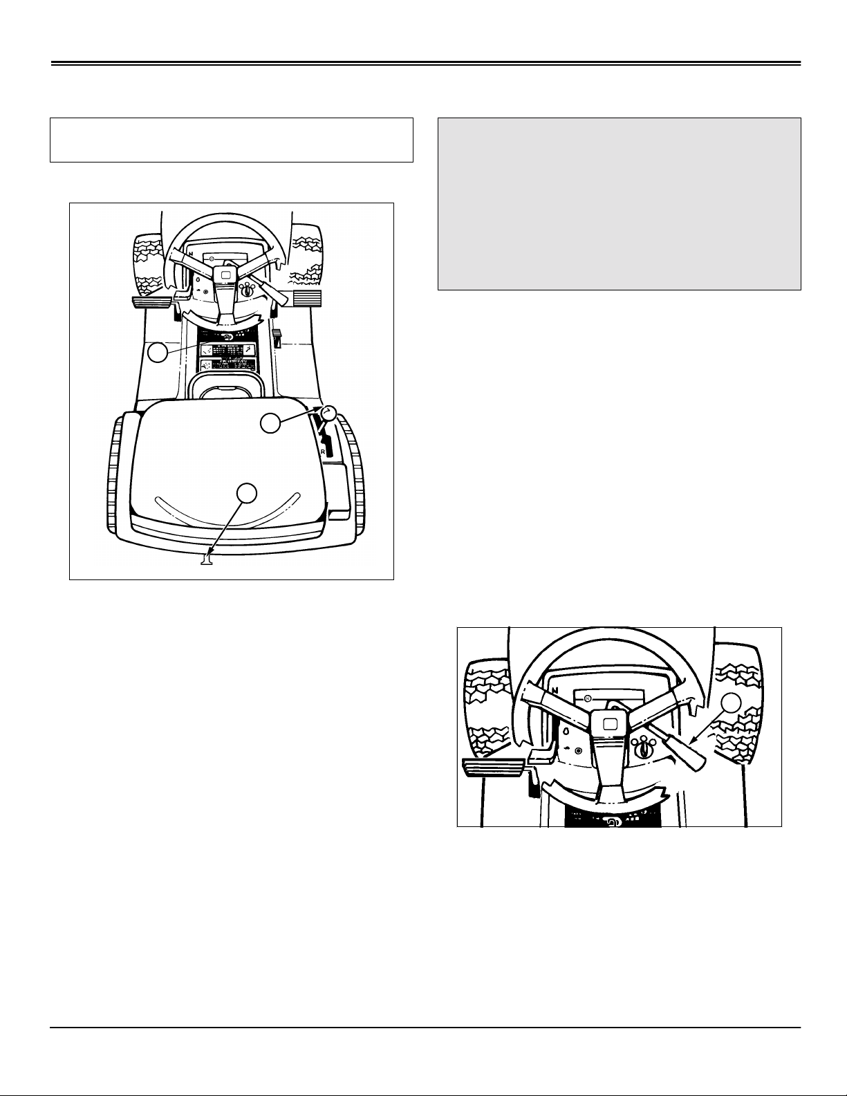
Using Lift Lever to Raise and Lower Mower
1. Push down on lift lev er (A) slightly and hold loc king le v er
(B) down with thumb.
2. Move lift lever (A) DOWN to LOWER mower or UP to
RAISE mower.
• First, test drive area with PTO lever DISENGAGED and
mower lowered. Slow down when you travel over rough
ground.
Avoid Injury From Contacting Blades
Before you dismount to unplug or adjust mower:
• DISENGAGE PTO lever to stop mower blades.
• STOP the engine.
3. Release locking lever lock (B) to keep lift lever (A) in
position.
Adjusting Cutting Height
Cutting height can be adjusted from 38 – 102 mm (1-1/2 –
4 in).
Check tractor tire pressure. (See Checking Tire Pressure in
Service Miscellaneous section.)
To adjust cutting height:
• LOCK the park brake.
• Remove key.
• Wait for mower blades to STOP.
• Keep hands, feet and clothing away from mower deck
Operating Mower - 16
1. Push down on lift lev er (A) slightly and hold loc king le v er
(B) down with thumb.
2. Move lift lever (A) to desired cutting height.
3. Release locking lev er (B) to k eep lift le ver (A) in position.
OPERATING MOWER
A
A
A
M40161
4. Adjust gage wheels to match cut height desired. (See
Adjusting Mower Gage Wheels below.)
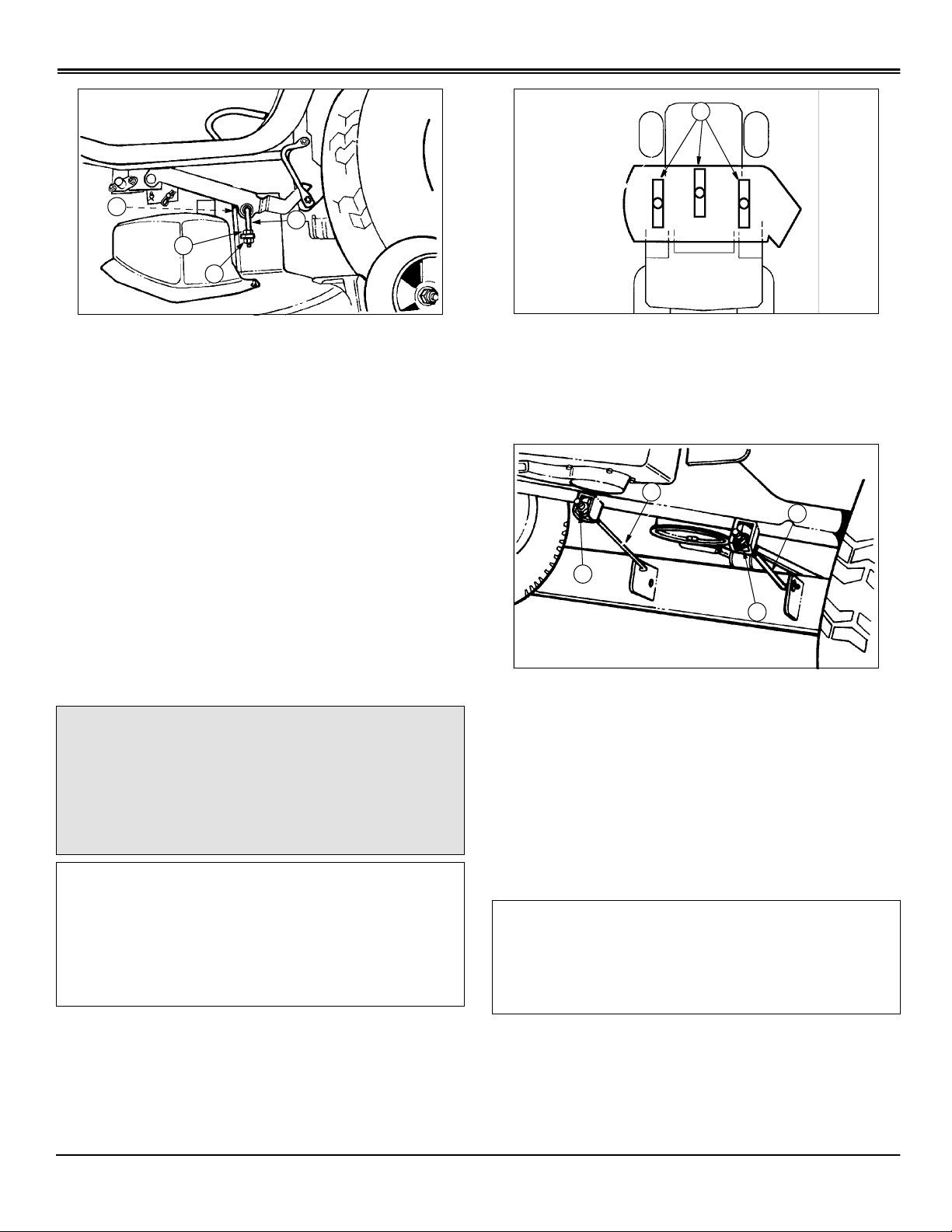
Adjusting Mower Gage Wheels
c
CAUTION: Avoid injury! Before you adjust gage
wheels: STOP engine, remove key, and wait for
blades to STOP.
IMPORTANT: Avoid damage! Mower gage wheels
must not ride on ground to support mower weight.
Adjust gage wheels each time you change cutting
height.
1. Check tractor tire pressure. Inflate tires to the correct
pressure. (See Checking Tire Pressure in Service Miscellaneous section.)
2. Raise mower lift lever to TRANSPORT (upper) position
and adjust cutting height. (See Adjusting Cutting Height in
this section.)
Adjusting Mower Level (Side-to-Side)
c
CAUTION: Avoid injury! Before you adjust
mower: STOP engine, remove key, and wait for
blades to STOP.
Be careful, sharp edges on mower blades.
Always wear gloves when handling mower
blades.
NOTE: A deck leveling gauge (P art Number TY15272) to
aid in deck leveling ma y be obtained through y our local
Authorized Service Center at a nominal cost.
1. Park tractor on a hard, level surface.
2. Stop engine and remove key.
3. CHECK: Tire pressures must be correct. (See Checking
Tire Pressure in Service – Miscellaneous section.)
4. Adjust cutting height to middle position.
D
C
B
3. Remove bolt (A), bushing (B), washer (C), and nut (D).
4. Move lift lever down to desired MOWING position.
5. Move mower gage wheels, one on each side, to one of
four holes for desired position. On 46-Inch Mower Deck,
move front and rear gage wheels.
6. Bottom of gage wheels should be approximately 6-13
mm (1/4-1/2 in) from the ground when properly adjusted.
7. Install bolt and tighten with nut.
A
M88571
5. Turn left blade parallel to tractor axle. Hold drive belt and
turn right blade parallel to axle.
6. Measure from each outside blade tip (A) to the level
Operating Mower - 17
surface. The difference between measurements must not
be more than 3 mm (1/8 in).
OPERATING MOWER
A
B
B
C
C
C
B
D
E
7. Loosen top clamping nut (C) facing inside of mower, on
left hand side J-bolt (B), approximately one turn.
8. Loosen upper adjusting nut (D).
9. Raise or lower left side of deck.
• To raise: Turn lower adjusting nut (E) towards rear of
tractor.
• To lower: T urn lower adjusting nut (E) to wards front of
tractor.
10.Tighten upper adjusting nut.
11.Tighten clamping nut.
12.Check side-to-side measurements and readjust if
necessary.
4. Turn blades so front blade tips (A) point straight forward.
5. Measure from the front of each blade tip to the level
surface. The front blade tips must be
lower than rear blade tips or blades will cut grass twice and
grass tips will turn brown.
6–9 mm (1/4–3/8 in.)
Adjusting Mower Level (Front-to-Rear)
c
CAUTION: Avoid injury! Before you adjust
mower: STOP engine, remove key, and wait for
blades to STOP.
Be careful, sharp edges on mower blades.
Always wear gloves when handling mower
blades.
IMPORTANT: Avoid damage! Make sure each front
draft rod is equally tensioned. The installed rods
should exhibit identical amounts of movement
between left and right rods. If one rod moves more
freely than the other, the adjustment nut should be
tightened until the movement of the assembly
matches that of the other side.
1. Park tractor on a hard, level surface.
2. Stop engine and remove key.
3. CHECK: Tire pressure must be correct. (See Checking
Tire Pressure in Service – Miscellaneous section.)
6. Turn nuts (B) on front draft rods (C) equally until
adjustment is correct. Turn nut clockwise to RAISE front of
mower deck or counterclockwise to LO WER front of mo wer
deck.
7. Check front-to-rear deck measurements and readjust if
necessary.
Engaging and Disengaging Mower
IMPORTANT: Avoid damage! Operate engine at
maximum speed when mowing or after mower blade
is engaged.
Machine may require 2–3 minutes warm-up period
before engaging the mower deck.
Engaging Mower
1. START engine.
Operating Mower - 18
Loading...